JP2010197015A - Driving unit of automatic ice making machine - Google Patents
Driving unit of automatic ice making machine Download PDFInfo
- Publication number
- JP2010197015A JP2010197015A JP2009045367A JP2009045367A JP2010197015A JP 2010197015 A JP2010197015 A JP 2010197015A JP 2009045367 A JP2009045367 A JP 2009045367A JP 2009045367 A JP2009045367 A JP 2009045367A JP 2010197015 A JP2010197015 A JP 2010197015A
- Authority
- JP
- Japan
- Prior art keywords
- ice
- making machine
- automatic
- unit
- drive unit
- Prior art date
- Legal status (The legal status is an assumption and is not a legal conclusion. Google has not performed a legal analysis and makes no representation as to the accuracy of the status listed.)
- Pending
Links
Images


Classifications
-
- F—MECHANICAL ENGINEERING; LIGHTING; HEATING; WEAPONS; BLASTING
- F25—REFRIGERATION OR COOLING; COMBINED HEATING AND REFRIGERATION SYSTEMS; HEAT PUMP SYSTEMS; MANUFACTURE OR STORAGE OF ICE; LIQUEFACTION SOLIDIFICATION OF GASES
- F25D—REFRIGERATORS; COLD ROOMS; ICE-BOXES; COOLING OR FREEZING APPARATUS NOT OTHERWISE PROVIDED FOR
- F25D23/00—General constructional features
- F25D23/12—Arrangements of compartments additional to cooling compartments; Combinations of refrigerators with other equipment, e.g. stove
-
- F—MECHANICAL ENGINEERING; LIGHTING; HEATING; WEAPONS; BLASTING
- F25—REFRIGERATION OR COOLING; COMBINED HEATING AND REFRIGERATION SYSTEMS; HEAT PUMP SYSTEMS; MANUFACTURE OR STORAGE OF ICE; LIQUEFACTION SOLIDIFICATION OF GASES
- F25C—PRODUCING, WORKING OR HANDLING ICE
- F25C2400/00—Auxiliary features or devices for producing, working or handling ice
- F25C2400/10—Refrigerator units
-
- F—MECHANICAL ENGINEERING; LIGHTING; HEATING; WEAPONS; BLASTING
- F25—REFRIGERATION OR COOLING; COMBINED HEATING AND REFRIGERATION SYSTEMS; HEAT PUMP SYSTEMS; MANUFACTURE OR STORAGE OF ICE; LIQUEFACTION SOLIDIFICATION OF GASES
- F25C—PRODUCING, WORKING OR HANDLING ICE
- F25C2400/00—Auxiliary features or devices for producing, working or handling ice
- F25C2400/14—Water supply
-
- F—MECHANICAL ENGINEERING; LIGHTING; HEATING; WEAPONS; BLASTING
- F25—REFRIGERATION OR COOLING; COMBINED HEATING AND REFRIGERATION SYSTEMS; HEAT PUMP SYSTEMS; MANUFACTURE OR STORAGE OF ICE; LIQUEFACTION SOLIDIFICATION OF GASES
- F25C—PRODUCING, WORKING OR HANDLING ICE
- F25C2600/00—Control issues
- F25C2600/04—Control means
-
- F—MECHANICAL ENGINEERING; LIGHTING; HEATING; WEAPONS; BLASTING
- F25—REFRIGERATION OR COOLING; COMBINED HEATING AND REFRIGERATION SYSTEMS; HEAT PUMP SYSTEMS; MANUFACTURE OR STORAGE OF ICE; LIQUEFACTION SOLIDIFICATION OF GASES
- F25C—PRODUCING, WORKING OR HANDLING ICE
- F25C2700/00—Sensing or detecting of parameters; Sensors therefor
- F25C2700/02—Level of ice
-
- F—MECHANICAL ENGINEERING; LIGHTING; HEATING; WEAPONS; BLASTING
- F25—REFRIGERATION OR COOLING; COMBINED HEATING AND REFRIGERATION SYSTEMS; HEAT PUMP SYSTEMS; MANUFACTURE OR STORAGE OF ICE; LIQUEFACTION SOLIDIFICATION OF GASES
- F25C—PRODUCING, WORKING OR HANDLING ICE
- F25C2700/00—Sensing or detecting of parameters; Sensors therefor
- F25C2700/12—Temperature of ice trays
-
- F—MECHANICAL ENGINEERING; LIGHTING; HEATING; WEAPONS; BLASTING
- F25—REFRIGERATION OR COOLING; COMBINED HEATING AND REFRIGERATION SYSTEMS; HEAT PUMP SYSTEMS; MANUFACTURE OR STORAGE OF ICE; LIQUEFACTION SOLIDIFICATION OF GASES
- F25D—REFRIGERATORS; COLD ROOMS; ICE-BOXES; COOLING OR FREEZING APPARATUS NOT OTHERWISE PROVIDED FOR
- F25D2400/00—General features of, or devices for refrigerators, cold rooms, ice-boxes, or for cooling or freezing apparatus not covered by any other subclass
- F25D2400/40—Refrigerating devices characterised by electrical wiring
-
- F—MECHANICAL ENGINEERING; LIGHTING; HEATING; WEAPONS; BLASTING
- F25—REFRIGERATION OR COOLING; COMBINED HEATING AND REFRIGERATION SYSTEMS; HEAT PUMP SYSTEMS; MANUFACTURE OR STORAGE OF ICE; LIQUEFACTION SOLIDIFICATION OF GASES
- F25D—REFRIGERATORS; COLD ROOMS; ICE-BOXES; COOLING OR FREEZING APPARATUS NOT OTHERWISE PROVIDED FOR
- F25D2700/00—Means for sensing or measuring; Sensors therefor
- F25D2700/02—Sensors detecting door opening
-
- F—MECHANICAL ENGINEERING; LIGHTING; HEATING; WEAPONS; BLASTING
- F25—REFRIGERATION OR COOLING; COMBINED HEATING AND REFRIGERATION SYSTEMS; HEAT PUMP SYSTEMS; MANUFACTURE OR STORAGE OF ICE; LIQUEFACTION SOLIDIFICATION OF GASES
- F25D—REFRIGERATORS; COLD ROOMS; ICE-BOXES; COOLING OR FREEZING APPARATUS NOT OTHERWISE PROVIDED FOR
- F25D29/00—Arrangement or mounting of control or safety devices
Abstract
Description
本発明は、冷蔵庫内などに設置される自動製氷機の駆動ユニットに関するものである。 The present invention relates to a drive unit for an automatic ice making machine installed in a refrigerator or the like.
家庭用冷蔵庫等などの冷蔵庫に取り付けられている自動製氷機は、製氷皿、検氷部材、および駆動ユニットを備えており、駆動ユニットは、ユニットケース内に製氷皿および検氷レバーの位置を検出する位置検出装置と、製氷皿および検氷部材を駆動する駆動部とを備えている(特許文献1、2参照)。
An automatic ice maker attached to a refrigerator such as a home refrigerator has an ice tray, an ice detection member, and a drive unit. The drive unit detects the position of the ice tray and ice detection lever in the unit case. And a drive unit that drives the ice tray and the ice detecting member (see
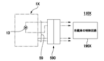
かかる自動製氷機を備えた冷蔵庫は、従来、図12に示すように、冷蔵庫本体100Xに、自動製氷機1Xを含めた冷蔵庫全体を制御する制御回路190Xが設けられている。従って、制御回路190Xは、自動製氷機1X側から出力された製氷皿の温度検出結果や、位置検出装置による製氷皿や検氷部材の位置検出結果などに基づいて制御信号を自動製氷機1Xに出力して、給水装置や、自動製氷機1Xの駆動部に設けられたモータ13を制御することにより、製氷皿への給水、貯氷部の氷量の確認、製氷皿からの離氷などを行なわせる。従って、自動製氷機1Xと冷蔵庫本体100X側とは配線群59およびコネクタ590を介して電気的に接続されている。
Conventionally, as shown in FIG. 12, a refrigerator equipped with such an automatic ice maker is provided with a
しかしながら、図12に示す構成では、自動製氷機1Xが搭載されていない冷蔵庫に自動製氷機1Xを組み込む場合や、既設の自動製氷機1Xを仕様の異なる自動製氷機1Xに交換する場合、冷蔵庫本体100Xに搭載されていた制御回路190Xを変更する必要があるという問題点がある。
However, in the configuration shown in FIG. 12, when the
以上の問題点に鑑みて、本発明では、冷蔵庫本体の制御回路を変更せずに自動製氷機の取り付けや交換を行なうことのできる自動製氷機の駆動ユニットを提供することにある。 In view of the above problems, it is an object of the present invention to provide a drive unit for an automatic ice maker that can attach or replace an automatic ice maker without changing the control circuit of the refrigerator body.
上記課題を解決するために、本発明に係る自動製氷機の駆動ユニットは、製氷皿および検氷部材を駆動するためのモータを備えた駆動部と、前記製氷皿および前記検氷部材の位置を検出する位置検出装置と、前記位置検出装置の検出信号に基づいて、前記モータの駆動を制御する制御部と、前記制御部、前記駆動部および前記位置検出装置が収容されたユニットケースと、を有することを特徴とする。 In order to solve the above problems, a drive unit of an automatic ice making machine according to the present invention includes a drive unit having a motor for driving an ice tray and an ice detecting member, and positions of the ice tray and the ice detecting member. A position detection device to detect, a control unit for controlling driving of the motor based on a detection signal of the position detection device, and a unit case in which the control unit, the drive unit and the position detection device are accommodated. It is characterized by having.
本発明では、自動製氷機の駆動ユニットにおいて、駆動部および位置検出装置が収容されたユニットケースには、制御部も収容されているため、自動製氷機が搭載されていない冷蔵庫に自動製氷機を組み込む場合や、既設の自動製氷機を仕様の異なる自動製氷機に交換する場合、冷蔵庫本体に搭載されていた制御回路については変更する必要がない。それ故、冷蔵庫本体の制御部を変更せずに、自動製氷機の取り付けや交換を行なうことができる。また、自動製氷機側と冷蔵庫本体側との間では、多数の制御信号の授受を行なう必要がないため、基本的には、自動製氷機側と冷蔵庫本体側との間は電源供給用の配線により接続すればよいなど、冷蔵庫本体との間の電気的な接続を簡素化することができる。 In the present invention, in the drive unit of the automatic ice maker, since the control unit is also housed in the unit case in which the drive unit and the position detection device are housed, the automatic ice maker is installed in the refrigerator not equipped with the automatic ice maker. When incorporating or replacing an existing automatic ice maker with a different specification, there is no need to change the control circuit mounted on the refrigerator body. Therefore, it is possible to attach or replace the automatic ice making machine without changing the control unit of the refrigerator body. In addition, since it is not necessary to exchange a large number of control signals between the automatic ice making machine side and the refrigerator main body side, basically the wiring for power supply is provided between the automatic ice making machine side and the refrigerator main body side. The electrical connection with the refrigerator body can be simplified.
本発明において、前記製氷皿の温度を検出するサーミスタに接続された配線は、前記ユニットケース内に接続され、前記制御部は、前記位置検出装置の検出信号、および前記サーミスタの検出信号に基づいて、前記モータの駆動を制御することが好ましい。このように構成すると、サーミスタの検出信号に基づいてモータの駆動を制御する場合であっても、冷蔵庫本体に搭載されていた制御回路については変更する必要がない。また、サーミスタは製氷皿近傍に配置されることから、サーミスタは、冷蔵庫本体側の制御回路よりもユニットケースに近い位置に配置される。従って、サーミスタに接続された配線をユニットケースに接続すれば、配線の長さを大幅に短縮することができる。 In the present invention, the wiring connected to the thermistor for detecting the temperature of the ice tray is connected to the unit case, and the control unit is based on the detection signal of the position detection device and the detection signal of the thermistor. It is preferable to control the driving of the motor. If comprised in this way, even if it is a case where the drive of a motor is controlled based on the detection signal of a thermistor, it is not necessary to change about the control circuit mounted in the refrigerator main body. Further, since the thermistor is disposed in the vicinity of the ice tray, the thermistor is disposed closer to the unit case than the control circuit on the refrigerator body side. Therefore, if the wiring connected to the thermistor is connected to the unit case, the length of the wiring can be greatly reduced.
本発明において、前記製氷皿に液体を供給する給液装置に接続された配線は、前記ユニットケース内に接続され、前記制御部は、前記給液装置を制御することが好ましい。このように構成すると、給液装置を設置した場合であっても、冷蔵庫本体に搭載されていた制御回路については変更する必要がない。また、給液装置は製氷皿近傍に配置されることから、給液装置は、冷蔵庫本体側の制御回路よりもユニットケースに近い位置に配置される。従って、給液装置に接続された配線をユニットケースに接続すれば、配線の長さを大幅に短縮することができる。 In this invention, it is preferable that the wiring connected to the liquid supply apparatus which supplies the liquid to the said ice tray is connected in the said unit case, and the said control part controls the said liquid supply apparatus. If comprised in this way, even if it is a case where a liquid supply apparatus is installed, it is not necessary to change about the control circuit mounted in the refrigerator main body. Further, since the liquid supply device is disposed in the vicinity of the ice tray, the liquid supply device is disposed at a position closer to the unit case than the control circuit on the refrigerator main body side. Therefore, if the wiring connected to the liquid supply device is connected to the unit case, the length of the wiring can be greatly reduced.
本発明を適用した自動製氷機の駆動ユニットにおいては、駆動部および位置検出装置が収容されたユニットケースに制御部も収容されているため、自動製氷機が搭載されていない冷蔵庫に自動製氷機を組み込む場合や、既設の自動製氷機を仕様の異なる自動製氷機に交換する場合、冷蔵庫本体に搭載されていた制御回路については変更する必要がない。それ故、冷蔵庫本体の制御部を変更せずに、駆動ユニットの取り付けや交換を行なうことができる。また、基本的には、自動製氷機側と冷蔵庫本体側との間は電源供給用の配線により接続すればよいなど、冷蔵庫本体との間の電気的な接続を簡素化することができる。 In the drive unit of the automatic ice maker to which the present invention is applied, the control unit is also housed in the unit case in which the drive unit and the position detection device are housed, so the automatic ice maker is installed in the refrigerator not equipped with the automatic ice maker. When incorporating or replacing an existing automatic ice maker with a different specification, there is no need to change the control circuit mounted on the refrigerator body. Therefore, the drive unit can be attached or replaced without changing the control unit of the refrigerator body. Basically, the electrical connection between the automatic ice maker and the refrigerator main body can be simplified, for example, by connecting the power supply wiring to the refrigerator main body.
図面を参照して、本発明を適用した自動製氷機の駆動ユニットを説明する。 A drive unit of an automatic ice making machine to which the present invention is applied will be described with reference to the drawings.
[全体構成]
(自動製氷機の基本構成)
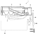
図1は、本発明を適用した自動製氷機の構成を示す説明図である。図1に示す自動製氷機1は、製氷や離氷等を自動的に行なう装置であり、冷蔵庫の製氷室内に設置される。自動製氷機1は、貯氷部20の上方に配置された製氷皿2と、貯氷部20内の貯氷量を検知するためのレバー状の検氷部材3と、製氷皿2に水を供給するための給水ポンプ11(給液装置)と、製氷皿2および検氷部材3を連動させて駆動する駆動ユニット5とを有している。また、自動製氷機1は、製氷皿2の温度を検出して製氷が終了したか否かを監視するためのサーミスタ7を備えている。
[overall structure]
(Basic configuration of automatic ice maker)
FIG. 1 is an explanatory diagram showing a configuration of an automatic ice making machine to which the present invention is applied. An automatic
かかる自動製氷機1において、駆動ユニット5は、製氷皿2を反転させて製氷皿2から貯氷部20内に氷を落下させる。かかる離氷動作の際、製氷皿2に設けた突出部(図示省略)が冷蔵庫本体あるいは自動製氷機1の機枠16に設けられた当接片(図示省略)に当たってねじれ変形を起こし、氷を落下させる。また、駆動ユニット5は、一点鎖線で示すように、検氷部材3を昇降させて貯氷部20内の氷量を検出する。
In the automatic
(駆動ユニット5の構成)
図2は、本発明を適用した自動製氷機の駆動ユニットと冷蔵庫本体との電気的な接続などを示す説明図である。
(Configuration of drive unit 5)
FIG. 2 is an explanatory diagram showing an electrical connection between the drive unit of the automatic ice making machine to which the present invention is applied and the refrigerator body.
図1および図2に示すように、駆動ユニット5は、製氷皿2および検氷部材3を駆動するためのモータ13を備えた駆動部50と、製氷皿2および検氷部材3の位置を検出する位置検出装置55と、ユニットケース9とを備えており、駆動部50および位置検出装置55はユニットケース9の内部に配置されている。位置検出装置55は、製氷皿2および検氷部材3の回転位置などに対応してオン・オフするタクトスイッチとして機能し、かかる位置検出装置55から出力される位置検出信号は、制御部6に入力される。
As shown in FIGS. 1 and 2, the
駆動ユニット5と冷蔵庫本体100とは、駆動ユニット5から延びた配線群59、および配線群59の端部に設けられたコネクタ590を介して接続されており、冷蔵庫本体100から駆動ユニット5には、配線群59およびコネクタ590を介して、例えばDC12Vの駆動電圧Vdd、およびグランド電位Vgndが供給されている。
The
本形態の自動製氷機1では、モータ13の制御を含めて自動製氷機1全体の制御を行なう制御部6が、冷蔵庫本体100の制御回路110とは別体に構成されており、制御部6は、駆動ユニット5のユニットケース9の内部に収納されている。このため、サーミスタ7に接続された配線70は、ユニットケース9内に設けられた制御部6に接続されており、サーミスタ7の検出結果は、冷蔵庫本体100を経由せずに直接、制御部6に入力される。また、本形態では、給水ポンプ11に接続された配線14もユニットケース9内に設けられた制御部6に接続されており、制御部6は、冷蔵庫本体100を経由せずに直接、給水ポンプ11を制御する。かかる配線14は、給水ポンプ11に対する電源線であり、給水ポンプ11の駆動は制御部6によって行なわれる。
In the automatic
このため、駆動ユニット5と冷蔵庫本体100とを電気的に接続する配線群59には、駆動電圧Vddおよびグランド電位Vgndを供給する配線は含まれているが、モータ13に対する配線、サーミスタ7に対する配線、給水ポンプ11に対する配線は含まれていない。
For this reason, the
なお、冷蔵庫本体100には、冷蔵庫の扉の開閉を監視する扉スイッチ150が設けられており、扉が開かれた際、自動製氷機1での検氷部材3の駆動や製氷皿2の駆動が停止される。このため、扉スイッチ150の検出信号は、冷蔵庫本体100の制御回路110を介して自動製氷機1に供給される。従って、配線群59には、扉スイッチ150の検出信号を冷蔵庫本体100から駆動ユニット5に供給するための扉開閉信号供給の配線が含まれている。
The refrigerator
(基本動作)
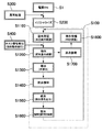
図3は、本発明を適用した自動製氷機1の基本動作を示すブロック図である。本形態の自動製氷機1において、制御部6は、マイクロコンピュータ、メモリ、タイマーなどにより構成されており、予めメモリに格納された動作プログラムに基づいて、図3を参照して説明する以下の工程を実行させる。
(basic action)
FIG. 3 is a block diagram showing the basic operation of the automatic
図3に示すように、ステップS1において自動製氷機1の電源がオンになると、自動製氷機1では、まず、ステップS200において、製氷皿2や検氷部材3を原点位置に戻すイニシャライズ工程を行ない、その後、ステップS100において基本動作を行なう。すなわち、自動製氷機1の作動中に停電等のトラブルで駆動ユニット5への電力の供給が絶たれた後に電力の供給が再開された場合、製氷皿2や検氷部材3の位置を把握できない。従って、自動製氷機1の電源がオンになると、まず、イニシャライズ工程を行なう。
As shown in FIG. 3, when the
本形態の自動製氷機1において、基本動作では、まず、ステップS1100において、サーミスタ7から出力された信号に基づいて、製氷皿2が所定温度以下に到達したか否かが判断され、製氷確認工程が行なわれる。次に、ステップS1200では、モータ13によって、検氷部材3を駆動して貯氷部20に所定量の氷があるか否かを確認する検氷工程が行なわれる。かかる検氷工程では、検氷部材3の先端を貯氷部20内に下降させ、その下降距離に基づいて貯氷部20内の氷量を検出する。
In the basic
かかる検氷工程において、貯氷部20に十分な量の氷があると判断された場合、ステップS1700において、モータ13により検氷部材3を原点位置に戻す原点復帰工程が行なわれた後、ステップS1800において検氷待機工程が行なわれ、その後、再度、ステップS1100の製氷確認工程が行なわれる。
In this ice detection process, if it is determined that there is a sufficient amount of ice in the
これに対して、ステップS1200での検氷工程において貯氷部20の氷量が少ないと判断された場合、ステップS1300での離氷工程において、モータ13により製氷皿2を駆動し、製氷皿2から貯氷部20に氷を排出させる。かかる離氷動作工程では、製氷皿2を反転させて離氷位置とし、貯氷部20内に氷を落下させる。
On the other hand, when it is determined that the ice amount in the
次に、ステップS1400において製氷皿2を元の位置に戻す原点復帰工程を行なった後、ステップS1500において給水ポンプ11を駆動させ、製氷皿2に水を供給する給水動作工程が行なわれる。そして、ステップS1600において製氷工程を行なう。
Next, in step S1400, after performing an origin return process for returning the
なお、本形態では、製氷などを行なっていない場合でも、組立後のテストなどを行なう際、ステップS400で強制動作実行指令が発せられると、ステップS1200の検氷工程が行なわれる。 In the present embodiment, even when ice making or the like is not performed, when a forced operation execution command is issued in step S400 when performing a test after assembly or the like, the ice detection process in step S1200 is performed.
また、上記の動作の途中に、冷蔵庫本体100で冷蔵庫の扉が操作されると、ステップS300の異常処理工程が行なわれ、しかる後に、ステップS200のイニシャライズ工程が行なわれる。
Further, when the refrigerator door is operated in the refrigerator
(本形態の主な効果)
以上説明したように、本形態の自動製氷機1の駆動ユニット5において、駆動部50および位置検出装置55が収容されたユニットケース9には、制御部6も収容されている。このため、自動製氷機1側と冷蔵庫本体100側との間では、多数の制御信号の授受を行なう必要がない。また、自動製氷機1が搭載されていない冷蔵庫に自動製氷機1を組み込む場合や、既設の自動製氷機1を仕様の異なる自動製氷機1に交換する場合、冷蔵庫本体100に搭載されていた制御回路110については変更する必要がなく、冷蔵庫本体100の制御回路110を変更せずに、自動製氷機1の取り付けや交換を行なうことができる。
(Main effects of this form)
As described above, in the
また、自動製氷機1側と冷蔵庫本体100側との間では、多数の制御信号の授受を行なう必要がないため、基本的には、自動製氷機1側と冷蔵庫本体100側との間は電源供給用の配線により接続すればよいなど、自動製氷機1と冷蔵庫本体100との間の電気的な接続を簡素化することができる。
In addition, since it is not necessary to exchange a large number of control signals between the
さらに、製氷皿2の温度を検出するサーミスタ7に接続された配線70は、ユニットケース9内に接続され、制御部6は、位置検出装置55の検出信号およびサーミスタ7の検出信号に基づいて、モータ13の駆動を制御する。このため、サーミスタ7の検出信号に基づいてモータ13の駆動を制御する場合であっても、冷蔵庫本体100の制御回路110については変更する必要がない。また、サーミスタ7は製氷皿2近傍に配置されることから、サーミスタ7は、冷蔵庫本体100側の制御回路110よりもユニットケース9に近い位置に配置される。従って、サーミスタ7に接続された配線70をユニットケース9に接続すれば、配線70の長さを大幅に短縮することができる。
Furthermore, the
さらにまた、製氷皿2に水を供給する給水ポンプ11に接続された配線14は、ユニットケース9内に接続されている。このため、給水ポンプ11を設置した場合であっても、冷蔵庫本体100の制御回路110については変更する必要がない。また、給水ポンプ11は製氷皿2近傍に配置されることから、給水ポンプ11は、冷蔵庫本体100側の制御回路110よりもユニットケース9に近い位置に配置される。従って、給水ポンプ11に接続された配線70をユニットケース9に接続すれば、配線70の長さを大幅に短縮することができる。なお、製氷皿2への給水は、給液装置の電磁バルブにより制御される場合があり、このような場合、電磁バルブに接続された配線70をユニットケース9に接続すれば、配線70の長さを大幅に短縮することができる。
Furthermore, the
[駆動ユニット5の具体的構成例]
(駆動部の構成)
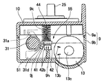
図4は、図1に示す自動製氷機の駆動ユニットにおいて、ユニットケースを構成する一方のケース部材を取り外して、駆動ユニットの内部構成を示す正面図である。図5は、図4に示す駆動ユニットの駆動輪列の連結関係を示す断面展開図である。図6は、図4の矢示IV−IV断面図である。
[Specific Configuration Example of Drive Unit 5]
(Configuration of drive unit)
FIG. 4 is a front view showing an internal configuration of the drive unit by removing one case member constituting the unit case in the drive unit of the automatic ice making machine shown in FIG. 1. FIG. 5 is a cross-sectional development view showing the connection relationship of the drive wheel trains of the drive unit shown in FIG. 6 is a cross-sectional view taken along arrow IV-IV in FIG.
図4および図5に示すように、駆動ユニット5は、製氷皿2および検氷部材3を駆動するための駆動部50を備えている。駆動部50は、製氷皿2に駆動輪列15を介して連結されてこれを反転させるカム車10と、このカム車10に操作されて検氷部材3を動作させる検氷軸31と、カム車10や検氷軸31の駆動源となるモータ13とを備えている。
As shown in FIGS. 4 and 5, the
また、駆動ユニット5は、製氷皿2および検氷軸31(検氷部材3)の回転位置を検出する位置検出装置55を備えており、位置検出装置55は、検氷部材3による氷の量の検出結果を検知するための押圧スイッチ42と、押圧スイッチ42を押圧/非押圧する押圧部材41とを備えている。
Further, the
かかる駆動部50および位置検出装置55は、ユニットケース9内の所定位置に収納されている。ユニットケース9は、2つのケース部材9a、9bからなり、ユニットケース9の内部には、モータ13および押圧スイッチ42の各端子が接続された回路基板51が収納されている。また、回路基板51に形成された孔51aには、モータ13の出力軸を軸受けする軸受けブッシュ13cが嵌っている。押圧スイッチ42は、モータ13と検氷軸31との間に配置され、モータ13の後側の端面に位置するモータ端子13bおよび押圧スイッチ42の側方に突出した端子42bは、この側壁と平行するように配置される回路基板51に接続されている。
The
さらに、回路基板51には、図2に示す制御部6を構成する半導体ICが実装され、制御部6は、ユニットケース9内に収納されている。なお、図1および図2を参照して説明した配線群59および配線14、70は、回路基板51に接続されている。
Further, a semiconductor IC constituting the
図6に示すように、駆動ユニット5では、ケース部材9bの底部に立設された凸部9hに、押圧スイッチ42の押圧部材41との接触面と反対側の面を直接的に接触させている。押圧スイッチ42は、押圧部材41によって、図4において紙面奥側に押圧されるが、この押圧スイッチ42の奥側には押圧スイッチ42を支持する凸部9hが、ケース部材9bの底面より立設されている。すなわち、押圧スイッチ42は、この回路基板51の基板面と押圧スイッチ42を押圧する押圧部材41の押圧方向とが平行となるように回路基板51上に取り付けられており、その後端面部分が凸部9hの上端面と直接的に接触するように配置されている。検氷軸31のスイッチ押圧動作阻止片31dは、押圧部材41の押圧スイッチ42の押圧を行なう側の面に直接当接するものとなっている。
As shown in FIG. 6, in the
(カム車10の構成)
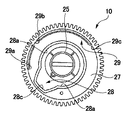
図7は、図5に示す駆動ユニットに用いたカム車を矢示V方向から見た底面図である。図4および図7に示すカム車10は、駆動源となるモータ13により回転させられる。カム車10には、出力軸25が一体成形されている。出力軸25は、ケース部材9aに設けられた孔から駆動ユニット5の外方に突出し、製氷皿2に連結されている。従って、カム車10と製氷皿2とは、一体となって回転する。出力軸25の製氷皿2に連結されていない側の端部は、筒状となっており、ケース部材9bに設けられた円形の台部9gに回転自在に支持されている。
(Composition of cam car 10)
FIG. 7 is a bottom view of the cam wheel used in the drive unit shown in FIG. The
(出力軸25、検氷軸31およびその周辺構成)
図8は、図4に示す駆動ユニットの検氷軸の正面図である。図9は、図4に示す駆動ユニットの押圧部材を矢示VII方向から見た底面図である。図4に示すように、出力軸25の端部外周面には、筒状のフリクション部材8がフリクション状態で遊嵌配置されている。フリクション部材8の外周面には、製氷位置方向(製氷皿2から氷を落下させる離氷位置方向とは反対側への回転方向)への駆動時に、検氷位置において検氷軸31の回転を阻止する回動阻止片(図示省略)が設けられ、回動阻止片は、カム車10と共にフリクション部材8が製氷位置方向に回動すると、図8に示す検氷軸31の係合片31bと係合する位置へ移動し、係合片31bと係合する。このため、検氷軸31は、製氷位置方向への駆動時、カム車10の検氷軸用カム面28の氷不足検出位置部28c(図7参照)に係合凸部31aが対向しても、上述の回動阻止片によって、その回動を阻止されるため、そのカム面形状に従って回動することはない。従って、検氷軸31が検氷位置にあっても、検氷軸31に形成されたスイッチ押圧動作阻止片31dは、押圧スイッチ42を押圧する押圧部材41の回動を阻止できず、押圧スイッチ42がオンとなる。すなわち、離氷動作後の製氷皿2の回転時においては、検氷位置で押圧部材41がコイルスプリング44の付勢力を受けて揺動し、押圧スイッチ42が貯氷部20内の氷の量に関係なく必ずオンとなる。
(
FIG. 8 is a front view of the ice detecting shaft of the drive unit shown in FIG. FIG. 9 is a bottom view of the pressing member of the drive unit shown in FIG. 4 as viewed from the direction of arrow VII. As shown in FIG. 4, a
一方、フリクション部材8の回動阻止片は、カム車10と共にフリクション部材8が離氷位置方向に回動すると、検氷軸31の係合片31bの回動範囲から外れた位置へ移動し、係合片31bと係合しない。このため、検氷軸31は、検氷位置において、後述する検氷軸用カム面28の凹面形状に従い自在に回動できる。
On the other hand, when the
一方、図5および図7に示すように、カム車10のケース部材9bに対向する側面10cには、環状の凹部27が形成されている。この凹部27内には、内壁をカム面とする検氷軸用カム面28が設けられていると共に、その外側に同様に内壁をカム面とする押圧部材動作用カム面29を構成している。検氷軸用カム面28および押圧部材動作用カム面29は、カム車10の回転中心となる軸に対してほぼ平行に延設された延設部の側壁の内周面部分に形成されている。そして、図7に示すように、検氷軸用カム面28は、検氷非動作位置部28aと、氷不足検出位置部28cとを有している。検氷非動作位置部28aは、検氷部材3を下降させない状態で維持させる区間となっている。また、氷不足検出位置部28cは、氷が不足している場合に検氷部材3を最下降させた状態で維持させる区間となっている。この氷不足検出位置部28cは、凹面形状となっている。検氷軸31は、係合凸部31aが氷不足検出位置部28cに嵌まるたびに、コイルスプリング32の付勢力によって回動しようとする。
On the other hand, as shown in FIGS. 5 and 7, an
また、図7に示すように、押圧部材動作用カム面29は、製氷位置において信号を出力させるための第1の信号発生用カム部29aと、検氷位置において信号を出力させるための第2の信号発生用カム部29bと、離氷位置において信号を出力させるための第3の信号発生用カム部29cとを有している。これらの各信号発生用カム部29a、29b、29cは、それぞれ凹みとなっている。押圧部材41は、カム当接部41aがこれらの凹みに嵌まるたびに、コイルスプリング44の付勢力によって押圧スイッチ42側に揺動しようとする。なお、検氷軸31が所定角度以上回転すると、検氷軸31に形成されたスイッチ押圧動作阻止片31dが、後述するように押圧スイッチ42を押圧する押圧部材41の回動を阻止する。かかる構成により、カム車10の回転角度が、製氷位置および離氷位置にある場合、すなわち製氷皿2が製氷のために水平に静止された状態および反転され氷がひねり落とされた状態で押圧スイッチ42がオンする。さらに、押圧スイッチ42は、検氷動作により氷が満氷である場合と、離氷後の製氷位置方向への駆動時における検氷位置通過時において検氷信号を出力する。このように、本実施の形態では、押圧スイッチ42は、検氷結果を知らせるための信号を出力すると共に、製氷皿2の位置検出のための信号を出力する。
Further, as shown in FIG. 7, the pressing member operating
このような構成により、製氷皿2が離氷位置方向に回動した時、貯氷部20内の氷が不足しているときは、検氷軸31が所定角度以上回転して、押圧スイッチ42がオン(押圧)されない。これに対して、貯氷部20内に氷が所定量以上貯められた状態のときは、検氷部材3が貯氷部20内の氷にぶつかって、検氷軸31が所定角度以上回動できないので、検氷軸31の係合片31bは押圧部材41の回動を阻止できない。そのため、この場合は、コイルスプリング44の付勢力により検氷位置において押圧部材41が揺動し、その揺動によって押圧スイッチ42を押圧する。
With such a configuration, when the
なお、検氷軸31は、カム車10によって操作され、最大35度まで回動可能となっている。検氷軸31は、図8に示すように、係合凸部31aと、係合片31bと、バネ係合部31cと、スイッチ押圧動作阻止片31dと、全周にわたって形成されたスラスト抜け防止突堤31eと、レバー連結部31fと、ケース受け部31gと、ガイド片31hとを有している。ケース受け部31gは、検氷軸31の一方の端部に凸状に形成されており、ケース部材9bに形成された受け孔(図示省略)に回動自在に支持される。レバー連結部31fは、検氷軸31の他方の端部でユニットケース9の外部に突出するように形成されており、検氷部材3の支点部が嵌め込まれる。検氷軸31は、ケース受け部31gを受け孔に先に差し込み、バネ係合部31cにコイルスプリング32を係合させ、係合凸部31aをカム車10の検氷軸用カム面28に押し付けた状態で、レバー連結部31f側をユニットケース9内に載置することにより、ユニットケース9内に回動自在に位置決めされる。係合凸部31aは、検氷軸31のケース受け部31gの近傍で検氷軸31の外周面から径方向外側に突出し、途中位置から湾曲した形状となっている。この係合凸部31aは、カム車10に形成された検氷軸用カム面28に当接するカムフォロアーとなっている。同様に、係合片31bは、検氷軸31の端部近傍でフリクション部材8の回動阻止片と当接可能とされている。ガイド片31hは、ケース部材9aの天板の裏側部分に形成されたガイド溝(図示省略)内に入り込み、このガイド溝に沿って移動するようになっている。このガイド片31hは、検氷軸31の回転範囲を規制するものとなっている。
The
図5に示すように、押圧部材41は、一方のケース部材9bの底面に立設された2つの端板53の上端縁部分に設けられた各U字状溝53a内に回動自在に支持されている。押圧部材41は、図9に示すように、側面から見ると、突起腕41bから突部41cが突出した形状になっており、突起腕41bは、コイルスプリング44に付勢された状態にある。突起腕41bは、検氷軸31に設けられたスイッチ押圧動作阻止片31dの近傍に位置しており、突起腕41bにスイッチ押圧動作阻止片31dが当たっている状態では、押圧部材41は揺動することができない。
As shown in FIG. 5, the pressing
突起腕41bと対向する位置には、押圧スイッチ42のボタン42aが配置されている。また、押圧部材41の突起腕41bの押圧スイッチ42と対向しない側の面には山形状の突部41cが設けられ、コイルスプリング44の一端内に入り込んでいる。なお、コイルスプリング44の他端は、図5に示すように、ケース部材9aに設けられた係合筒21c内に入れられ、係合筒21c内の軸(図示省略)がその端部内に入り込んでいる。
A
押圧部材41の中心部は、揺動を支える回動支持部41dとなっており、この回動支持部41dの両端が各U字状溝53a内に入り、この回動支持部41dを中心として揺動する。さらに、押圧部材41には、揺動規制部41eが設けられており、カム当接部41aがカム車10から周方向の力を受けても揺動規制部41eの端面が端板53の内壁によって規制される。そのため、押圧部材41は、回動支持部41dの片方がU字状溝53aの底部から浮き上がって傾くことがなく、揺動中心がずれずに正確に押圧部材動作用カム面29に沿って動作する。
The central portion of the pressing
[自動製氷機1の具体的動作]
(基本動作)
図10は本発明を適用した自動製氷機の駆動ユニットで行なわれる基本動作の具体的な内容を示すフローチャートである。
[Specific operation of automatic ice making machine 1]
(basic action)
FIG. 10 is a flowchart showing specific contents of the basic operation performed in the drive unit of the automatic ice making machine to which the present invention is applied.
図2に示す制御部6は、基本動作プログラムおよび初期設定プログラムを適宜実行し、図3を参照して説明した動作を実現する。なお、基本動作プログラムを実行していない場合には、カム車10は製氷位置に位置し、この状態で、製氷皿2は水平に保持され、検氷部材3は、製氷皿2の側方に格納されている。
The
以下、図10に示す基本動作プログラムに沿って、自動製氷機1の基本動作を説明する。かかる基本動作は、冷蔵庫の扉が閉められた状態にあって、製氷皿2に氷ができていることを確認できた場合に実行される。
Hereinafter, the basic operation of the automatic
まず、ステップS1において自動製氷機1の電源がオンになると、自動製氷機1では、まず、ステップS200においてイニシャライズ工程を行ない、その後、ステップS100の基本動作を行なう。基本動作では、ステップS1100の製氷確認工程において、サーミスタ7から出力された信号に基づいて、製氷皿2が所定温度以下、より具体的には−10℃以下に到達したか否かが判断される。かかる製氷確認工程において、製氷皿2が−10℃以下に到達している場合、製氷が完了したものと判断され、ステップS1200の検氷工程が行なわれる。
First, when the power of the
次に、ステップS1200の検氷工程では、モータ13によって、検氷部材3を駆動して貯氷部20に所定量の氷があるか否かの検氷が行なわれる。かかる検氷では、まず、ステップS101において、モータ13を正転させてカム車10を時計周りCWに回転させる。次に、制御部6は、ステップS102において、位置検出信号がオフか否かを判断し、オフが検出されるまでこのステップS102を繰り返し実行する。オフを検出できずにオンが検出されている状態では、カム車10は、未だ製氷位置から十分に回転していない。そして、カム車10が時計周りCWに十分に回転すると、位置検出信号がオンからオフに変化するので、制御部6はステップS103においてタイマーに所定の時間をセットする。この時間は、制御部6が貯氷部20内の貯氷量を検出するのに要する時間よりも十分長い時間である。この時間が経過するまでに検氷位置信号(オフ)を検出できなかった場合には、貯氷部20内の貯氷量は不足していることになる。すなわち、カム車10が時計周りCWに回転した際、貯氷部20内の貯氷量が不足している場合には、検氷部材3は貯氷部20内の氷に邪魔されることなく所定位置まで下降することができるが、貯氷部20内は満氷状態にある場合、検氷部材3は貯氷部20内の氷に邪魔される結果、位置検出信号がオンのままである。本例では、時間は7秒間に設定されている。
Next, in the ice detection process of step S1200, the
ステップS104、S105において、設定した時間の間、位置検出信号がオフになれば、ステップS1300の離氷動作工程を行なう。これに対して、設定した時間の間に位置検出信号がオンのままであれば、原点復帰動作工程(ステップS1700)および検氷待機工程(ステップS1800)を行なう。 In steps S104 and S105, if the position detection signal is turned off for the set time, the ice removing operation process in step S1300 is performed. On the other hand, if the position detection signal remains on during the set time, an origin return operation step (step S1700) and an ice detection standby step (step S1800) are performed.
ステップS1300の離氷動作工程では、ステップS106において、位置検出信号がオフからオンに変化したか否かを判別し、位置検出信号がオンになれば、ステップS107でモータ13は1秒間停止する。位置検出信号がオフからオンに切り換わった際のオン信号は、離氷位置信号である。この状態では、製氷皿2はねじれ変形しており、製氷皿2より氷が外れて貯氷部20内に落下する。
In the ice removing operation process of step S1300, it is determined in step S106 whether or not the position detection signal has changed from OFF to ON. If the position detection signal is turned ON, the
次に、原点復帰工程(ステップS1400)を行なう。この原点復帰工程では、まず、ステップS108において、モータ13を逆回転させ、カム車10を反時計周りCCWに回転させる。次に、ステップS109で位置検出信号がオンからオフに変化したか否かを判別する。オン状態にある間、カム車10は離氷位置から未だ十分に離れるに至っていない。従って、制御部6は、オフを検出するまでステップS109を繰り返し実行する。次に、ステップS110において、位置検出信号がオフからオンに変化したか否かを判別する。そして、位置検出信号がオンに変化するまで、ステップS110を繰り返し実行する。カム車10が反時計周りCCWにさらに回転し、その回転角が所定角度まで戻ると、位置検出信号がオンからオフに変化する。これにより、ステップS111の判別結果が肯定になり、制御部6はステップS112に進む。ステップS112では、位置検出信号がオフからオンに変化したか否かを判別する。そして、制御部6はオン信号を検出するまで、このステップS112を繰り返し実行する。すなわち、反時計周りCCWに回転しているカム車10が製氷位置にまで復帰すると、位置検出信号がオフからオンに変化する。そして、ステップS113においてタイマーを0.5秒に設定し、ステップS114で設定時間が経過したと判断すると、ステップS115でモータ13の回転を停止させる。この状態で、空になった製氷皿2は水平状態に戻されている。
Next, an origin return process (step S1400) is performed. In this return to origin process, first, in step S108, the
次に、ステップS1500の給水工程では、ステップS116において、制御部6は給水ポンプ11を作動させ、製氷皿2に給水を行なう。
Next, in the water supply process of step S1500, in step S116, the
次に、ステップS1600の製氷工程では、ステップS117でタイマーを60分に設定し、ステップS118において60分経過すると、ステップS1100の製氷確認工程に戻る。 Next, in the ice making process in step S1600, the timer is set to 60 minutes in step S117, and when 60 minutes have passed in step S118, the process returns to the ice making confirmation process in step S1100.
なお、ステップS1200の検氷工程において、貯氷部20内の貯氷量が充足している場合には、製氷皿2を反転させて離氷作業を行なう必要はなく、直ちに製氷皿2を製氷位置に復帰させるべきである。そこで、ステップS125でモータ13を1秒間停止させた後、ステップS1700の原点復帰工程を行なう。この原点復帰工程では、まず、ステップS126でモータ13を逆転させ、カム車10を反時計周りCCWに回転させる。次に、ステップS127で位置検出信号がオフされたことを確認でき、ステップS128で位置検出信号がオンになったことが確認できた後、ステップS129でタイマーを0.5秒に設定する。次に、ステップS130で0.5秒が経過したことを確認すると、ステップS131でモータ13を停止させる。
In the ice detection process in step S1200, when the ice storage amount in the
次に、ステップS1800の検氷待機工程では、ステップS132でタイマーを60分に設定し、ステップS133で60分が経過したことを確認すると、ステップS1100の製氷確認工程に戻る。 Next, in the ice detection standby process in step S1800, the timer is set to 60 minutes in step S132, and when it is confirmed in step S133 that 60 minutes have elapsed, the process returns to the ice making confirmation process in step S1100.
(異常処理工程)
図11は、本発明を適用した自動製氷機の駆動ユニットで行なわれる異常処理の具体的内容を示すフローチャートである。
(Abnormal processing process)
FIG. 11 is a flowchart showing the specific contents of the abnormality processing performed in the drive unit of the automatic ice making machine to which the present invention is applied.
図10を参照して説明した基本動作を行なっているときに、冷蔵庫の扉が開かれて氷の取り出し動作が行なわれると、危険である。そこで、冷蔵庫の扉が開かれると、図2に示す扉スイッチ150から出力された信号が冷蔵庫本体100の制御回路110を介して自動製氷機1に供給され、以下の異常処理工程が行なわれる。
When the basic operation described with reference to FIG. 10 is performed, it is dangerous if the refrigerator door is opened and the ice is taken out. Therefore, when the refrigerator door is opened, a signal output from the
この異常処理工程では、まず、ステップS301で冷蔵庫の扉が開かれたと確認されると、ステップS302で自動製氷機1における各部材の位置が判定される。かかる判定において、ステップS303で各部材の位置が原点でないと判断されると、ステップS304でモータ13を停止させ、ステップS305で扉が閉じられるまで待機する。そして、ステップS305で扉が閉じられたと判断できた場合にはイニシャライズ工程(図10参照)に戻る。これに対して、ステップS303で各部材の位置が原点であると判断された場合、ステップS306、S307で扉が閉められるまでの待機が行なわれ、扉が閉じられたと判断できた場合には、異常処理工程を終了し、イニシャライズ工程(図10参照)に戻る。
In this abnormality processing step, first, when it is confirmed in step S301 that the refrigerator door has been opened, the position of each member in the automatic
1 自動製氷機
2 製氷皿
3 検氷部材
5 駆動ユニット
7 サーミスタ
9 ユニットケース
10 カム車
11 給水ポンプ(給液装置)
13 モータ
50 駆動部
55 位置検出装置
100 冷蔵庫本体
DESCRIPTION OF
13
Claims (3)
前記製氷皿および前記検氷部材の位置を検出する位置検出装置と、
前記位置検出装置の検出信号に基づいて前記モータの駆動を制御する制御部と、
前記制御部、前記駆動部および前記位置検出装置が収容されたユニットケースと、
を有することを特徴とする自動製氷機の駆動ユニット。 A drive unit having a motor for driving the ice tray and the ice detecting member;
A position detecting device for detecting positions of the ice tray and the ice detecting member;
A control unit for controlling driving of the motor based on a detection signal of the position detection device;
A unit case in which the control unit, the drive unit and the position detection device are accommodated;
A drive unit for an automatic ice maker characterized by comprising:
前記制御部は、前記位置検出装置の検出信号、および前記サーミスタの検出信号に基づいて、前記モータの駆動を制御することを特徴とする請求項1に記載の自動製氷機の駆動ユニット。 The wiring connected to the thermistor for detecting the temperature of the ice tray is connected in the unit case,
The drive unit of the automatic ice making machine according to claim 1, wherein the control unit controls driving of the motor based on a detection signal of the position detection device and a detection signal of the thermistor.
前記制御部は、前記給液装置を制御することを特徴とする請求項1または2に記載の自動製氷機の駆動ユニット。 The wiring connected to the liquid supply device for supplying liquid to the ice tray is connected in the unit case,
The drive unit of the automatic ice maker according to claim 1, wherein the control unit controls the liquid supply device.
Priority Applications (3)
| Application Number | Priority Date | Filing Date | Title |
|---|---|---|---|
| JP2009045367A JP2010197015A (en) | 2009-02-27 | 2009-02-27 | Driving unit of automatic ice making machine |
| CN201010126451.1A CN101818976B (en) | 2009-02-27 | 2010-02-23 | Drive unit for automatic ice maker |
| US12/712,757 US8499571B2 (en) | 2009-02-27 | 2010-02-25 | Drive unit for automatic ice maker |
Applications Claiming Priority (1)
| Application Number | Priority Date | Filing Date | Title |
|---|---|---|---|
| JP2009045367A JP2010197015A (en) | 2009-02-27 | 2009-02-27 | Driving unit of automatic ice making machine |
Publications (2)
| Publication Number | Publication Date |
|---|---|
| JP2010197015A true JP2010197015A (en) | 2010-09-09 |
| JP2010197015A5 JP2010197015A5 (en) | 2012-02-23 |
Family
ID=42654167
Family Applications (1)
| Application Number | Title | Priority Date | Filing Date |
|---|---|---|---|
| JP2009045367A Pending JP2010197015A (en) | 2009-02-27 | 2009-02-27 | Driving unit of automatic ice making machine |
Country Status (3)
| Country | Link |
|---|---|
| US (1) | US8499571B2 (en) |
| JP (1) | JP2010197015A (en) |
| CN (1) | CN101818976B (en) |
Cited By (5)
| Publication number | Priority date | Publication date | Assignee | Title |
|---|---|---|---|---|
| JP2014105946A (en) * | 2012-11-28 | 2014-06-09 | Nidec Sankyo Corp | Ice making device, ice making device body, and ice making tray attachment detection method in ice making device |
| JP2018044727A (en) * | 2016-09-15 | 2018-03-22 | 東芝ライフスタイル株式会社 | Automatic ice-making device |
| JP2019045044A (en) * | 2017-08-31 | 2019-03-22 | 日本電産サンキョー株式会社 | Ice making device and inspection method thereof |
| WO2020179445A1 (en) * | 2019-03-06 | 2020-09-10 | 日本電産サンキョー株式会社 | Ice-making device |
| JP7373181B2 (en) | 2019-07-10 | 2023-11-02 | アイリスオーヤマ株式会社 | Refrigerator and automatic ice making device |
Families Citing this family (14)
| Publication number | Priority date | Publication date | Assignee | Title |
|---|---|---|---|---|
| US8893523B2 (en) * | 2010-11-22 | 2014-11-25 | General Electric Company | Method of operating a refrigerator |
| KR101913423B1 (en) * | 2011-09-09 | 2018-12-31 | 엘지전자 주식회사 | refrigerator |
| KR20130078531A (en) * | 2011-12-30 | 2013-07-10 | 삼성전자주식회사 | Refrigerator |
| CN103712393B (en) * | 2012-09-28 | 2016-04-27 | 日本电产三协株式会社 | Ice maker |
| CN103925733A (en) * | 2013-01-10 | 2014-07-16 | 刘威孝 | Simple air-conditioner |
| US9032744B2 (en) | 2013-01-14 | 2015-05-19 | General Electric Company | Ice maker for a refrigerator appliance and a method for operating the same |
| CN103851877B (en) * | 2014-02-28 | 2016-01-20 | 海信容声(广东)冰箱有限公司 | A kind of control method of automatic ice maker of refrigerator system |
| US9482456B2 (en) * | 2014-09-24 | 2016-11-01 | Hani Toma | Automatic turning ice block apparatus and method |
| CN104729176A (en) * | 2015-03-25 | 2015-06-24 | 青岛海尔股份有限公司 | Ice-making device and refrigerator containing ice-making device |
| JP6902435B2 (en) * | 2017-08-31 | 2021-07-14 | 日本電産サンキョー株式会社 | Ice maker |
| JP6902436B2 (en) * | 2017-08-31 | 2021-07-14 | 日本電産サンキョー株式会社 | Drive unit for ice making equipment and ice making equipment |
| JP6889637B2 (en) * | 2017-08-31 | 2021-06-18 | 日本電産サンキョー株式会社 | Ice maker |
| CN110081641A (en) * | 2019-05-09 | 2019-08-02 | 广东奥马冰箱有限公司 | A kind of automatic ice maker ice storage box structure |
| US11543166B2 (en) | 2020-03-31 | 2023-01-03 | Electrolux Home Products, Inc. | Ice maker |
Citations (1)
| Publication number | Priority date | Publication date | Assignee | Title |
|---|---|---|---|---|
| JP2002181421A (en) * | 2001-11-13 | 2002-06-26 | Sankyo Seiki Mfg Co Ltd | Automated ice making machine |
Family Cites Families (7)
| Publication number | Priority date | Publication date | Assignee | Title |
|---|---|---|---|---|
| JPH07122539B2 (en) * | 1989-11-16 | 1995-12-25 | 株式会社東芝 | Refrigerator with automatic ice maker |
| US5735130A (en) * | 1995-11-30 | 1998-04-07 | Samsung Electronics Co., Ltd. | Ice removal motor control circuit and method for an automatic ice maker |
| KR970047507A (en) * | 1995-12-27 | 1997-07-26 | 김광호 | How to control the ice machine of automatic ice maker |
| JP3086649B2 (en) | 1996-01-17 | 2000-09-11 | 株式会社三協精機製作所 | Drive for automatic ice maker |
| JP3909190B2 (en) | 2000-04-25 | 2007-04-25 | 日本電産サンキョー株式会社 | Automatic ice machine drive |
| KR100826019B1 (en) * | 2006-10-20 | 2008-04-28 | 엘지전자 주식회사 | ice making apparatus |
| CN101158527B (en) * | 2007-10-29 | 2010-11-24 | 刘勇 | Ice making device and control method thereof |
-
2009
- 2009-02-27 JP JP2009045367A patent/JP2010197015A/en active Pending
-
2010
- 2010-02-23 CN CN201010126451.1A patent/CN101818976B/en active Active
- 2010-02-25 US US12/712,757 patent/US8499571B2/en active Active
Patent Citations (1)
| Publication number | Priority date | Publication date | Assignee | Title |
|---|---|---|---|---|
| JP2002181421A (en) * | 2001-11-13 | 2002-06-26 | Sankyo Seiki Mfg Co Ltd | Automated ice making machine |
Cited By (6)
| Publication number | Priority date | Publication date | Assignee | Title |
|---|---|---|---|---|
| JP2014105946A (en) * | 2012-11-28 | 2014-06-09 | Nidec Sankyo Corp | Ice making device, ice making device body, and ice making tray attachment detection method in ice making device |
| JP2018044727A (en) * | 2016-09-15 | 2018-03-22 | 東芝ライフスタイル株式会社 | Automatic ice-making device |
| JP2019045044A (en) * | 2017-08-31 | 2019-03-22 | 日本電産サンキョー株式会社 | Ice making device and inspection method thereof |
| WO2020179445A1 (en) * | 2019-03-06 | 2020-09-10 | 日本電産サンキョー株式会社 | Ice-making device |
| JP2020143833A (en) * | 2019-03-06 | 2020-09-10 | 日本電産サンキョー株式会社 | Ice making device |
| JP7373181B2 (en) | 2019-07-10 | 2023-11-02 | アイリスオーヤマ株式会社 | Refrigerator and automatic ice making device |
Also Published As
| Publication number | Publication date |
|---|---|
| US20100218524A1 (en) | 2010-09-02 |
| CN101818976B (en) | 2014-01-01 |
| US8499571B2 (en) | 2013-08-06 |
| CN101818976A (en) | 2010-09-01 |
Similar Documents
| Publication | Publication Date | Title |
|---|---|---|
| JP2010197015A (en) | Driving unit of automatic ice making machine | |
| US20100319385A1 (en) | Cam mechanism and ice making device | |
| JP3582706B2 (en) | Automatic ice machine drive, automatic ice machine and refrigerator | |
| JP3672176B2 (en) | Automatic ice machine drive | |
| JP3827272B2 (en) | Driving device for automatic ice making machine and method for manufacturing the same | |
| JP3296967B2 (en) | Drive for automatic ice maker | |
| JP3547354B2 (en) | Driving device for automatic ice making machine and method for manufacturing the same | |
| JP6088225B2 (en) | Ice making device, device body of ice making device, and ice tray mounting detection method for ice making device | |
| JP3672177B2 (en) | Automatic ice machine drive | |
| KR20010062149A (en) | Driving apparatus of a automatic making-ice machine | |
| JP3879808B2 (en) | Automatic ice machine drive | |
| JP2010246721A (en) | Home electric appliance, and method of detecting state of lid of the home electric appliance | |
| JP3879808B6 (en) | Automatic ice machine drive | |
| JP3540882B2 (en) | Drive for automatic ice maker | |
| JP2013155926A (en) | Automatic ice making machine and automatic ice making machine unit | |
| JP3306618B2 (en) | Automatic ice machine | |
| JP2010236785A (en) | Automatic ice making device | |
| JP3385204B2 (en) | How to drive an automatic ice machine | |
| JP2000088413A (en) | Ice making apparatus | |
| JP2006122148A (en) | Toilet bowl device | |
| JP2023008039A (en) | ice dispenser | |
| JP3826397B2 (en) | Storage | |
| JP4077918B2 (en) | Automatic ice machine | |
| JP2009187125A (en) | Non-contact type ic medium processor | |
| JP5314466B2 (en) | Coin dispenser |
Legal Events
| Date | Code | Title | Description |
|---|---|---|---|
| A521 | Request for written amendment filed |
Free format text: JAPANESE INTERMEDIATE CODE: A523 Effective date: 20120110 |
|
| A621 | Written request for application examination |
Free format text: JAPANESE INTERMEDIATE CODE: A621 Effective date: 20120110 |
|
| A977 | Report on retrieval |
Free format text: JAPANESE INTERMEDIATE CODE: A971007 Effective date: 20130227 |
|
| A131 | Notification of reasons for refusal |
Free format text: JAPANESE INTERMEDIATE CODE: A131 Effective date: 20130319 |
|
| A02 | Decision of refusal |
Free format text: JAPANESE INTERMEDIATE CODE: A02 Effective date: 20130716 |