JP3824529B2 - Input device - Google Patents
Input device Download PDFInfo
- Publication number
- JP3824529B2 JP3824529B2 JP2001389478A JP2001389478A JP3824529B2 JP 3824529 B2 JP3824529 B2 JP 3824529B2 JP 2001389478 A JP2001389478 A JP 2001389478A JP 2001389478 A JP2001389478 A JP 2001389478A JP 3824529 B2 JP3824529 B2 JP 3824529B2
- Authority
- JP
- Japan
- Prior art keywords
- display
- input device
- vibration
- switch
- switch unit
- Prior art date
- Legal status (The legal status is an assumption and is not a legal conclusion. Google has not performed a legal analysis and makes no representation as to the accuracy of the status listed.)
- Expired - Fee Related
Links
- 239000004973 liquid crystal related substance Substances 0.000 description 17
- 230000006870 function Effects 0.000 description 14
- 230000000007 visual effect Effects 0.000 description 13
- 238000010586 diagram Methods 0.000 description 6
- 239000011159 matrix material Substances 0.000 description 4
- 238000001514 detection method Methods 0.000 description 3
- 230000000694 effects Effects 0.000 description 2
- 230000035807 sensation Effects 0.000 description 2
- 239000003086 colorant Substances 0.000 description 1
- 239000011521 glass Substances 0.000 description 1
- 230000003287 optical effect Effects 0.000 description 1
- 230000015541 sensory perception of touch Effects 0.000 description 1
- 125000006850 spacer group Chemical group 0.000 description 1
- 239000000758 substrate Substances 0.000 description 1
Images

Landscapes
- Input From Keyboards Or The Like (AREA)
- Position Input By Displaying (AREA)
- User Interface Of Digital Computer (AREA)
Description
【0001】
【発明の属する技術分野】
本発明は入力装置に関し、特にスイッチ部を押したときにスイッチ部から機械的振動がフィードバックされると共に、スイッチ部に積層された液晶ディスプレーの表示が変化する入力装置に関する。
【0002】
【従来の技術】
従来のスイッチ装置は、複数の操作機能項目を有する表示部を有し、表示部とは別に設けられてタッチ操作することによって複数の機能項目を選択入力するタッチパネルを備えたタッチ操作部を有している。タッチ操作部にはタッチパネルに振動を発生させる振動発生部を備え、振動制御部が振動発生部を制御してタッチパネルの操作位置によって異なる振動を発生させるようになっている。操作者はタッチパネルを操作する指に異なる振動を受けることによりどの機能項目を選択入力したかが指先の触覚だけで分かりブラインドタッチで操作できるようになっている。
【0003】
【発明が解決しようとする課題】
上記した従来のスイッチ装置においては、指先の触覚だけで操作する機能が振動により分かるには習熟が必要で、慣れるのに時間がかかり、また、スイッチの認知度の向上という点では問題があった。
【0004】
本発明の目的は、スイッチ部のどの部分を押したかがはっきりと分かるスイッチ部を有する入力装置を提供することにある。
【0005】
【課題を解決するための手段】
本発明の入力装置は、ディスプレーと、このディスプレーの上に積層されて形成された振動フィルムと、この振動フィルムの上に積層されて形成されたスイッチ部と、制御部とを備え、前記制御部は、前記スイッチ部からの入力に伴い、前記振動フィルムと前記ディスプレーへ信号を送り、前記スイッチ部の操作位置に対応する前記振動フィルムの部分を振動させると共に、前記ディスプレーの前記スイッチ部の操作位置に対応する表示を変化させた構成とした。
この構成により、振動に加えて液晶ディスプレーの表示を変化させたため、スイッチ部の認知度を増すことができる。
【0006】
前記表示の変化は前記表示の位置を移動させた構成とした。
この構成により、表示の位置を動かしたためスイッチ部の視覚的な認知度を増すことができる。
【0007】
前記表示の変化は、前記表示の位置を上下または左右に往復移動させた構成とした。
この構成により、表示の位置を上下または左右に動かしたためスイッチ部の視覚的な認知度を増すことができる。
【0008】
前記表示の変化は、前記表示の大きさが相対的に小さい状態と大きい状態との間を移動するようにした構成とした。
この構成により、表示の大きさが相対的に小さい状態と大きい状態との間を振動するようにしたためスイッチ部の視覚的な認知度を増すことができる。
【0009】
前記表示の変化は、前記表示の大きさが大きくなるようにした構成とした。
この構成により、表示の大きさが大きくなるようにしたため、スイッチ部の視覚的な認知度を増すことができる。
【0010】
前記表示の変化は、前記表示を回転させた構成とした。
この構成により、表示を回転させたため、スイッチ部の視覚的な認知度を増すことができる。
【0011】
前記表示の変化は、前記表示の色を変えた構成とした。
この構成により、スイッチ部の視覚的な認知度を更に増すことができる。
【0012】
前記スイッチ部の操作位置に対応する位置の前記振動フィルムの振動モードを前記位置によって変えた構成とした。
この構成により、触覚的な認知度が加わるため、更にスイッチ部の認知度を増すことができる。
【0013】
【発明の実施の形態】
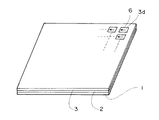
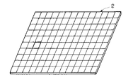
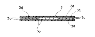
本発明の入力装置の実施形態を図1から図4を用いて説明する。図1は本発明の入力装置の実施形態の斜視図、図2は本発明の入力装置の実施形態の振動フィルムの斜視図、図3は本発明の入力装置の実施形態の振動フィルムの一区画の斜視図、図4は本発明の入力装置の実施形態のタッチパネルの断面図である。
【0014】
ディスプレーの1種である液晶ディスプレー1は、ガラス基板の間に液晶を挟んで電極を配した通常のものであり、スイッチの位置を示す表示を有している。
【0015】
振動フィルムには例えば、圧電フィルムや静電フィルムがあるが、実施形態の記載では静電フィルムについて説明する。
振動フィルム2は、積層された複数の透光性の圧電シート2bを2枚の透明フィルム2aで上下から挟んでおり、上端の透明フィルム2aの下面側と下端の透明フィルム2aの上面側には透明電極2cが形成されている。振動フィルム2は升目状の区画に分かれて、それぞれ個別に配線され個別に振動するようになっている。振動フィルム2は上下の透明電極に高電圧を印加すると厚さが薄くなり、高電圧を取り除くと厚さが戻り、高電圧の印加と無負荷を高速で繰り返す繰り返し周波数により振動フィルム2が厚さ方向に振動するようになっている。この繰り返し周波数を制御することにより振動フィルム2の振動の周波数を制御できる。また、振動フィルム2は液晶ディスプレー1の上に積層されている。
【0016】
タッチパネル3は、2枚の透明フィルム3aでスペーサ3bを挟んだ構造になっており、上側の透明フィルム3aの下面側と下側の透明フィルム3aの上面側には透明電極3cがパターン化され、スイッチ部3dが設けられている。タッチパネル3は振動フィルム2の上に積層されて設けられている。
以上により、本発明の入力装置の実施形態が構成されている。
尚、上記本発明の実施形態の説明では、振動フィルムとして静電フィルムの説明をしたが、圧電フィルムも静電フィルムと同様の機能を備えるため、圧電フィルムに置き換えても構わない。
【0017】
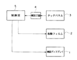
次に、本発明の入力装置の動作を図5を用いて説明する。図5は本発明の入力装置の実施形態のブロック図である。
【0018】
タッチパネル3のスイッチ部3dの任意の箇所(操作位置)を押圧して信号を入力すると、その信号は検知手段4により検知されて制御部5に伝えられる。検知手段4からの信号を受けた制御部5は、押圧されたタッチパネル3のスイッチ部3dに対応する振動フィルム2の部分を所定の振動モードで振動させる。また、制御部5は押圧されたタッチパネル3のスイッチ部3dに対応する部分の液晶ディスプレー1の表示6を視覚的に左右または上下に動かして振動させたり、液晶ディスプレー1の表示6が相対的に小さい状態と大きい状態との間を移動させて視覚的に振動するか、または表示6が大きくなるようにしている。
【0019】
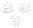
図6により、液晶ディスプレー1の表示6の動作を説明する。図6は本発明の入力装置の実施形態の表示の動作を説明する説明図である。図6Aに示すように液晶ディスプレー1の表示6は実線で示された矩形6aと矩形の中に配置された実線の矢印6bである。表示6が左右方向に動く場合を説明すると、この表示6が左方向に動くと矩形6aは左方向にずれて矩形6cとなり、矢印6bも左方向にずれて矢印6dとなる。表示6が右方向に動くと矩形6aは右方向にずれて矩形6eとなり、矢印6bも右方向にずれて矢印6fとなる。表示6は上記した右方向に動いた位置と左方向に動いた位置の間を往復移動して視覚的に振動する。
【0020】
図6Bに示すように、表示6が上下方向に動作する場合を説明すると、この表示6が上方向に動くと矩形6aは上方向にずれて矩形6gとなり、矢印6bも上方向にずれて矢印6hとなる。表示6が下方向に動くと矩形6aは下方向にずれて矩形6iとなり、矢印6bも下方向にずれて矢印6jとなる。表示6は上記した上方向に動いた位置と下方向に動いた位置の間を往復移動してして視覚的に振動する。以上の左右方向の視覚的な振動と上下方向の視覚的な振動は交互に行ってもよい。
【0021】
図6Cに示すように、表示6が相対的に大きさが小さい状態と大きい状態との間を動作する場合を説明すると、この表示6が大きくなると矩形6aは拡大して矩形6kとなり矢印6bも拡大して矢印6lとなる。表示6が元の大きさに戻ると大きさは相対的に小さくなる。表示6は元の大きさと大きくなった状態との間を往復移動して視覚的に振動する。この場合表示6は必ずしも元の大きさまで戻る必要はなく、大きくなった状態に対して相対的に小さい状態に戻ればよい。また、表示6が拡大して矩形6aが矩形6kとなり矢印6bが矢印6lになった状態で動作を止めてもよい。この場合表示6が大きくなったことだけでもスイッチ部3dの認知度を高めることができる。
また、図示しないが、表示6をその中心位置を中心にして回転させるようにしてもよい。このようにすれば、更に表示の認知度を上げることができる。
以上のように、表示6を動作させることによりスイッチ部3dがどのスイッチであるかの視覚的な認知度を増すことができる
【0022】
以上の液晶ディスプレー1の表示6の動作は、振動フィルム2の振動と同時に発生している。従って、操作者は指先で振動を感じ取るのと同時に視覚的に表示6の動作を認知し、どのスイッチを押圧したかの認知度が増大する。この場合、振動フィルム2の振動モードは一定のものでよい。その場合は振動フィルム2の振動はスイッチ部3dに入力がなされたか否かを確認するだけになる。また、表示6の動作に対応するように振動フィルム2の振動の振動モード(振動周波数及び波形)をスイッチ部3dの位置によって変えると、スイッチ部3dは触覚と視覚の両方でどのスイッチが入力されたかを認知できることになるので、スイッチ部3dの認知度は更に増大する。
【0023】
また、上記した液晶ディスプレー1の表示6の動作と振動フィルムの振動に加えてスイッチ部3dの入力に対応して表示6の色を変えると、更に操作者のスイッチ部3dの認知度を上げることができる。
【0024】
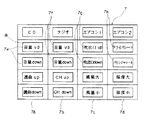
次に、上記した本発明の入力装置の実施形態の具体例を図7を用いて車載用機器のスイッチマトリックスで説明する。図7は本発明の入力装置の実施形態の車載用のスイッチマトリックスのパネルを示す図である。
【0025】
図7に示すように、車載用スイッチマトリックス7のスイッチの機能としては、CD、ラジオ、エアコンをそれぞれ操作するもので、それぞれの機能別のスイッチ群が設けられている。
【0026】
CDの操作機能を持つスイッチ群7aの表示7eは、上から下へ、矩形の枠で囲まれて「音量up」、「音量down」、「選局up」、「選局down」の順に並んでいる。このスイッチ群7aは入力されると「音量up」等の各表示7eの動作モードが上下方向に振動するようになっている。更に、振動の幅は下へ行く程大きくなるようになっている。従って、振動の幅によって個別のスイッチを識別できる。
【0027】
ラジオの操作機能を持つスイッチ群7bの表示7fは、上から下へ、矩形の枠で囲まれて「音量up」、「音量down」、「CHup」、「CHdown」の順に並んでいる。このスイッチ群7bは入力されると「音量up」等の各表示7fの動作モードが左右方向に視覚的に振動するようになっている。更に、この視覚的な振動の幅は下へ行く程大きくなるようになっている。従って、この場合も視覚的な振動の幅によって個別のスイッチを識別できる。
【0028】
エアコン1の操作機能を持つスイッチ群7cの表示7gは、上から下へ、矩形の枠で囲まれて「吹き出し口up」、「吹き出し口down」、「風量大」、「風量小」の順に並んでいる。このスイッチ群7cは入力されると「吹き出し口up」等の各表示7gの動作モードが相対的に表示の小さい状態と表示の大きい状態との間で視覚的に振動するようになっている。更に、この視覚的な振動の幅は下へ行く程大きくなるようになっている。従って、この場合も同様に視覚的な振動の幅によって個別のスイッチを識別できる。
【0029】
エアコン2の操作機能を持つスイッチ群7dの表示は、上から下へ矩形の枠で囲まれて「ドライバシート」、「パセンジャシート」、「温度大」、「温度小」の順に並んでいる。このスイッチ群7dは入力されると「ドライバシート」等の各表示7hの動作モードが大きくなるようになっている。更に、表示の大きくなる程度は下へ行く程大きくなるようになっている。従って、この場合は表示の大きさによって個別のスイッチを識別できる。
【0030】
以上のように、同一機能の各スイッチ群7a、7b、7c、7dは、入力したときの表示の動作モードが同じになるようになっているので、表示の動作モードを見ればどの機能のスイッチ群に入力したかの認知度は増大する。また、全てのスイッチ部で表示の動作は全て違っているので、表示の動作モード、振動の幅または表示の大きさを見れば各個別のスイッチを識別できる。
【0031】
また、各表示7e、7f、7g、7hの動作モード、振動の幅または表示の大きさに同期させて振動フィルム2の振動モード(振動の周波数および波形)を変えるようにすると、振動の周波数だけでも各スイッチ部8を識別でき、触覚と視覚の両方で識別できるのでスイッチ部8の認知度は更に上がる。
【0032】
また、各表示7e、7f、7g、7hはスイッチ部8の入力に応じて色が変わるようにする。色の変わり方は各スイッチ部が個別の色に変わってもよいし、同一機能のスイッチ群7a、7b、7c、7dの各表示7e、7f、7g、7hは同じ色になるようにしてもよい。この構成により各表示の認知度は更に上がる。
【0033】
尚、上記実施形態の具体例においてはスイッチ部8の入力に伴い表示の動作モードを変えてスイッチ部8の識別を行ったが、本発明はこれに限定されることなく、各表示の種類を変えて識別を行ってもよい。例えば上記実施形態では表示に文字を使っているが、スイッチ部8の入力に応じて表示の文字がアイコンに変わるようにしてもよい。
また、上記実施形態の具体例においては、ディスプレーを液晶ディスプレーとして説明したが、本発明はこれに限定されることなく、同様の機能を備えるディスプレーであれば同様の効果を奏することは言うまでもない。
また、上記実施形態の具体例においては、タッチパネルをフィルムタイプのものとして説明したが、本発明はこれに限定されることなく、タッチパネルは光学式のものであってもよい。
【0034】
【発明の効果】
以上説明したように、本発明の入力装置は、液晶ディスプレーと、この液晶ディスプレーの上に積層されて形成された振動フィルムと、この振動フィルムの上に積層されて形成され複数のスイッチ部を有するタッチパネルと、制御部とを備え、制御部は、タッチパネルのスイッチ部の入力に伴い、振動フィルムと液晶ディスプレーへ信号を送り、タッチパネルのスイッチ部の位置に対応する振動フィルムの部分を振動させると共に、液晶ディスプレーのスイッチ部の位置に対応する表示を変化させた。
【0035】
この構成により、機械的な振動に加えて液晶ディスプレーの表示を変化させたため、スイッチ部の認知度を増すことができる。
【図面の簡単な説明】
【図1】本発明の入力装置の実施形態の斜視図である。
【図2】本発明の入力装置の実施形態の振動フィルムの斜視図である。
【図3】本発明の入力装置の実施形態の振動フィルムの一区画の斜視図である。
【図4】本発明の入力装置の実施形態のタッチパネルの断面図である。
【図5】本発明の入力装置の実施形態のブロック図である。
【図6】本発明の入力装置の実施形態の表示の動作を説明する説明図である。
【図7】本発明の入力装置の実施形態の車載用のスイッチマトリックスのパネルを示す図である。
【符号の説明】
1 液晶ディスプレー
2 振動フィルム
3 タッチパネル
3d スイッチ部
4 検知手段
5 制御部
6 表示
7 スイッチマトリックス
7e、7f、7g、7h 表示
8 スイッチ部[0001]
BACKGROUND OF THE INVENTION
The present invention relates to an input device, and more particularly, to an input device in which mechanical vibration is fed back from a switch unit when a switch unit is pressed and the display of a liquid crystal display stacked on the switch unit is changed.
[0002]
[Prior art]
A conventional switch device has a display unit having a plurality of operation function items, and has a touch operation unit provided separately from the display unit and provided with a touch panel for selecting and inputting a plurality of function items by touch operation. ing. The touch operation unit includes a vibration generation unit that generates vibration on the touch panel, and the vibration control unit controls the vibration generation unit to generate different vibrations depending on the operation position of the touch panel. The operator knows which function item has been selected and inputted by receiving different vibrations on the finger operating the touch panel, and can operate by blind touch only by the tactile sense of the fingertip.
[0003]
[Problems to be solved by the invention]
In the conventional switch device described above, it is necessary to be proficient in order to understand the function operated only by the sense of touch of the fingertip by vibration, it takes time to get used to it, and there is a problem in terms of improving the degree of recognition of the switch .
[0004]
An object of the present invention is to provide an input device having a switch portion that clearly shows which portion of the switch portion is pressed.
[0005]
[Means for Solving the Problems]
An input device according to the present invention includes a display, a vibration film formed by being laminated on the display, a switch unit formed by being laminated on the vibration film, and a control unit. In response to an input from the switch unit, a signal is sent to the vibration film and the display to vibrate a portion of the vibration film corresponding to the operation position of the switch unit, and the operation position of the switch unit of the display The display corresponding to is changed.
With this configuration, since the display on the liquid crystal display is changed in addition to the vibration, the degree of recognition of the switch unit can be increased.
[0006]
The change in the display is configured such that the position of the display is moved.
With this configuration, since the display position is moved, the visual recognition degree of the switch unit can be increased.
[0007]
The change in the display is configured such that the display position is reciprocated up and down or left and right.
With this configuration, since the display position is moved up and down or left and right, the visual recognition degree of the switch unit can be increased.
[0008]
The change in the display is configured to move between a relatively small state and a large state of the display.
With this configuration, since the display is vibrated between a relatively small state and a large state, the visual recognition degree of the switch unit can be increased.
[0009]
The change in the display is configured to increase the size of the display.
With this configuration, since the display size is increased, the visual recognition degree of the switch unit can be increased.
[0010]
The display is changed by rotating the display.
With this configuration, since the display is rotated, the visual recognition degree of the switch unit can be increased.
[0011]
The display is changed by changing the display color.
With this configuration, the visual recognition degree of the switch unit can be further increased.
[0012]
The vibration mode of the vibration film at a position corresponding to the operation position of the switch unit is changed according to the position.
With this configuration, since tactile recognition is added, the recognition of the switch unit can be further increased.
[0013]
DETAILED DESCRIPTION OF THE INVENTION
An embodiment of an input device of the present invention will be described with reference to FIGS. 1 is a perspective view of an embodiment of the input device of the present invention, FIG. 2 is a perspective view of a vibration film of the embodiment of the input device of the present invention, and FIG. 3 is a section of the vibration film of the embodiment of the input device of the present invention. FIG. 4 is a sectional view of a touch panel according to an embodiment of the input device of the present invention.
[0014]
A liquid crystal display 1 which is a kind of display is a normal one in which electrodes are arranged with a liquid crystal sandwiched between glass substrates, and has a display indicating the position of a switch.
[0015]
For example, the vibration film includes a piezoelectric film and an electrostatic film. In the description of the embodiment, the electrostatic film will be described.
The
[0016]
The touch panel 3 has a structure in which a spacer 3b is sandwiched between two
The embodiment of the input device of the present invention is configured as described above.
In the above description of the embodiment of the present invention, the electrostatic film has been described as the vibration film. However, the piezoelectric film may have a function similar to that of the electrostatic film, and may be replaced with a piezoelectric film.
[0017]
Next, the operation of the input device of the present invention will be described with reference to FIG. FIG. 5 is a block diagram of an embodiment of the input device of the present invention.
[0018]
When a signal is input by pressing an arbitrary position (operation position) of the
[0019]
The operation of the
[0020]
As shown in FIG. 6B, the case where the
[0021]
As shown in FIG. 6C, the case where the
Although not shown, the
As described above, by operating the
The above operation of the
[0023]
In addition to the operation of the
[0024]
Next, a specific example of the embodiment of the input device of the present invention will be described with reference to FIG. FIG. 7 is a diagram showing an in-vehicle switch matrix panel according to an embodiment of the input device of the present invention.
[0025]
As shown in FIG. 7, the switch function of the in-vehicle switch matrix 7 is for operating a CD, a radio, and an air conditioner, and a switch group for each function is provided.
[0026]
The display 7e of the
[0027]
The display 7f of the
[0028]
The display 7g of the switch group 7c having the operation function of the air conditioner 1 is surrounded by a rectangular frame from top to bottom in the order of "blowout port up", "blowout port down", "large air volume", and "low air volume". Are lined up. When the switch group 7c is input, the operation mode of each display 7g such as “blow-up port” is visually oscillated between a relatively small display state and a large display state. Furthermore, the width of this visual vibration increases as it goes down. Accordingly, in this case as well, individual switches can be identified by the visual vibration width.
[0029]
The display of the
[0030]
As described above, the
[0031]
Further, if the vibration mode (vibration frequency and waveform) of the
[0032]
The colors of the displays 7e, 7f, 7g, and 7h are changed according to the input of the
[0033]
In the specific example of the above embodiment, the
Moreover, in the specific example of the said embodiment, although the display was demonstrated as a liquid crystal display, it cannot be overemphasized that this invention will show the same effect, if it is a display provided with the same function, without being limited to this.
Moreover, in the specific example of the said embodiment, although the touch panel was demonstrated as a film type thing, this invention is not limited to this, A touch panel may be an optical thing.
[0034]
【The invention's effect】
As described above, the input device of the present invention has a liquid crystal display, a vibration film formed by being laminated on the liquid crystal display, and a plurality of switch portions formed by being laminated on the vibration film. With a touch panel and a control unit, the control unit sends a signal to the vibration film and the liquid crystal display in accordance with the input of the switch unit of the touch panel, and vibrates the portion of the vibration film corresponding to the position of the switch unit of the touch panel. The display corresponding to the position of the switch part of the liquid crystal display was changed.
[0035]
With this configuration, since the display of the liquid crystal display is changed in addition to mechanical vibration, the degree of recognition of the switch unit can be increased.
[Brief description of the drawings]
FIG. 1 is a perspective view of an embodiment of an input device of the present invention.
FIG. 2 is a perspective view of a vibration film according to an embodiment of the input device of the present invention.
FIG. 3 is a perspective view of a section of the vibration film according to the embodiment of the input device of the present invention.
FIG. 4 is a cross-sectional view of a touch panel according to an embodiment of the input device of the present invention.
FIG. 5 is a block diagram of an embodiment of an input device of the present invention.
FIG. 6 is an explanatory diagram illustrating a display operation of the input device according to the embodiment of the invention.
FIG. 7 is a diagram showing an in-vehicle switch matrix panel according to an embodiment of the input device of the present invention.
[Explanation of symbols]
DESCRIPTION OF SYMBOLS 1
Claims (8)
Priority Applications (1)
| Application Number | Priority Date | Filing Date | Title |
|---|---|---|---|
| JP2001389478A JP3824529B2 (en) | 2001-12-21 | 2001-12-21 | Input device |
Applications Claiming Priority (1)
| Application Number | Priority Date | Filing Date | Title |
|---|---|---|---|
| JP2001389478A JP3824529B2 (en) | 2001-12-21 | 2001-12-21 | Input device |
Publications (2)
| Publication Number | Publication Date |
|---|---|
| JP2003186622A JP2003186622A (en) | 2003-07-04 |
| JP3824529B2 true JP3824529B2 (en) | 2006-09-20 |
Family
ID=27597684
Family Applications (1)
| Application Number | Title | Priority Date | Filing Date |
|---|---|---|---|
| JP2001389478A Expired - Fee Related JP3824529B2 (en) | 2001-12-21 | 2001-12-21 | Input device |
Country Status (1)
| Country | Link |
|---|---|
| JP (1) | JP3824529B2 (en) |
Families Citing this family (18)
| Publication number | Priority date | Publication date | Assignee | Title |
|---|---|---|---|---|
| EP2428865B1 (en) * | 2003-07-28 | 2012-11-28 | NEC Corporation | Mobile information terminal |
| JP4543863B2 (en) * | 2004-10-05 | 2010-09-15 | ソニー株式会社 | Input/output devices and electronic devices with tactile functions |
| US7890863B2 (en) | 2006-10-04 | 2011-02-15 | Immersion Corporation | Haptic effects with proximity sensing |
| US20090002328A1 (en) * | 2007-06-26 | 2009-01-01 | Immersion Corporation, A Delaware Corporation | Method and apparatus for multi-touch tactile touch panel actuator mechanisms |
| KR101522735B1 (en) * | 2008-09-03 | 2015-05-26 | 엘지전자 주식회사 | Mobile terminal |
| KR101516982B1 (en) | 2008-12-24 | 2015-04-30 | 삼성전자주식회사 | Vibration touch sensor, method of vibration touch sensing and vibration touch screen display panel |
| JP2010286986A (en) * | 2009-06-10 | 2010-12-24 | Funai Electric Co Ltd | Mobile terminal device |
| JP2011002926A (en) * | 2009-06-17 | 2011-01-06 | Hitachi Ltd | Display device with tactile exhibition function |
| KR101070137B1 (en) * | 2009-08-21 | 2011-10-05 | 삼성전기주식회사 | Touch feedback panel, touch screen device and electronic device including the same |
| JP2011242386A (en) * | 2010-04-23 | 2011-12-01 | Immersion Corp | Transparent compound piezoelectric material aggregate of contact sensor and tactile sense actuator |
| JP5813301B2 (en) * | 2010-09-01 | 2015-11-17 | 京セラ株式会社 | Display device |
| KR101602663B1 (en) * | 2011-10-10 | 2016-03-14 | 한국전자통신연구원 | Electronic device case for supporting tactile feedback and operating method thereof |
| US20140139451A1 (en) * | 2012-11-20 | 2014-05-22 | Vincent Levesque | Systems and Methods For Providing Mode or State Awareness With Programmable Surface Texture |
| CN104981759B (en) * | 2013-02-01 | 2018-03-13 | 株式会社村田制作所 | Display panel with compression sensor and the electronic equipment with pressing input function |
| JP6276385B2 (en) | 2013-04-26 | 2018-02-07 | イマージョン コーポレーションImmersion Corporation | Passive stiffness and active deformation haptic output device for flexible displays |
| JP2015130168A (en) * | 2013-12-31 | 2015-07-16 | イマージョン コーポレーションImmersion Corporation | Friction augmented control, and method to convert buttons of touch control panels to friction augmented controls |
| US10401962B2 (en) | 2016-06-21 | 2019-09-03 | Immersion Corporation | Haptically enabled overlay for a pressure sensitive surface |
| WO2021024567A1 (en) * | 2019-08-07 | 2021-02-11 | 株式会社村田製作所 | Surface-direction vibration structure |
Family Cites Families (6)
| Publication number | Priority date | Publication date | Assignee | Title |
|---|---|---|---|---|
| JPH0520226U (en) * | 1991-08-27 | 1993-03-12 | 信越ポリマー株式会社 | Flat input device |
| JPH09192353A (en) * | 1995-10-12 | 1997-07-29 | Konami Co Ltd | Icon display control device, command input support, control and recording medium storing computer program |
| JP4567817B2 (en) * | 1997-09-11 | 2010-10-20 | ソニー株式会社 | Information processing apparatus and control method thereof |
| JPH11338629A (en) * | 1998-05-27 | 1999-12-10 | Nec Corp | Pointing device |
| JP2000089877A (en) * | 1998-09-16 | 2000-03-31 | Ricoh Co Ltd | Display device and computer-readable recording medium |
| JP3469479B2 (en) * | 1998-10-26 | 2003-11-25 | パイオニア株式会社 | Video display operating device |
-
2001
- 2001-12-21 JP JP2001389478A patent/JP3824529B2/en not_active Expired - Fee Related
Also Published As
| Publication number | Publication date |
|---|---|
| JP2003186622A (en) | 2003-07-04 |
Similar Documents
| Publication | Publication Date | Title |
|---|---|---|
| JP3824529B2 (en) | Input device | |
| US20050057528A1 (en) | Screen having a touch-sensitive user interface for command input | |
| JP3906150B2 (en) | Touch-sensitive display with tactile feedback | |
| JP5529663B2 (en) | Input device | |
| JP5265433B2 (en) | Display device and program | |
| KR101013467B1 (en) | Touch screen for touch and display device having same | |
| JP2005352987A (en) | Key input device | |
| US20150160772A1 (en) | Input device | |
| JP2014102660A (en) | Manipulation assistance system, manipulation assistance method, and computer program | |
| WO2019017284A1 (en) | Input device | |
| JP2014102656A (en) | Manipulation assistance system, manipulation assistance method, and computer program | |
| JP2009098899A (en) | Information presentation device | |
| JP2009087351A (en) | touch screen | |
| JP4853611B2 (en) | Tactile sense providing mechanism and electronic device provided with tactile sense providing mechanism | |
| JP2021081956A (en) | Display device | |
| CN101868776A (en) | Haptic input/output device and driving method thereof | |
| JP2011123723A (en) | Input device for vehicle | |
| JP6115421B2 (en) | Input device and input system | |
| JPH06139018A (en) | Display device | |
| WO2019004049A1 (en) | Input device | |
| JP2017199200A (en) | Touch manipulation device | |
| JP2014102658A (en) | Operation support system, operation support method, and computer program | |
| US20200142489A1 (en) | Input device | |
| JP4108378B2 (en) | Switch device | |
| JP2014100998A (en) | Operation support system, operation support method, and computer program |
Legal Events
| Date | Code | Title | Description |
|---|---|---|---|
| A621 | Written request for application examination |
Free format text: JAPANESE INTERMEDIATE CODE: A621 Effective date: 20040512 |
|
| A977 | Report on retrieval |
Free format text: JAPANESE INTERMEDIATE CODE: A971007 Effective date: 20060615 |
|
| TRDD | Decision of grant or rejection written | ||
| A01 | Written decision to grant a patent or to grant a registration (utility model) |
Free format text: JAPANESE INTERMEDIATE CODE: A01 Effective date: 20060620 |
|
| A61 | First payment of annual fees (during grant procedure) |
Free format text: JAPANESE INTERMEDIATE CODE: A61 Effective date: 20060627 |
|
| FPAY | Renewal fee payment (event date is renewal date of database) |
Free format text: PAYMENT UNTIL: 20100707 Year of fee payment: 4 |
|
| FPAY | Renewal fee payment (event date is renewal date of database) |
Free format text: PAYMENT UNTIL: 20110707 Year of fee payment: 5 |
|
| FPAY | Renewal fee payment (event date is renewal date of database) |
Free format text: PAYMENT UNTIL: 20120707 Year of fee payment: 6 |
|
| FPAY | Renewal fee payment (event date is renewal date of database) |
Free format text: PAYMENT UNTIL: 20130707 Year of fee payment: 7 |
|
| LAPS | Cancellation because of no payment of annual fees |