JP3823731B2 - Error correction decoder - Google Patents
Error correction decoder Download PDFInfo
- Publication number
- JP3823731B2 JP3823731B2 JP2001008435A JP2001008435A JP3823731B2 JP 3823731 B2 JP3823731 B2 JP 3823731B2 JP 2001008435 A JP2001008435 A JP 2001008435A JP 2001008435 A JP2001008435 A JP 2001008435A JP 3823731 B2 JP3823731 B2 JP 3823731B2
- Authority
- JP
- Japan
- Prior art keywords
- path
- traceback
- state
- decoder
- error correction
- Prior art date
- Legal status (The legal status is an assumption and is not a legal conclusion. Google has not performed a legal analysis and makes no representation as to the accuracy of the status listed.)
- Expired - Fee Related
Links
Images


Landscapes
- Error Detection And Correction (AREA)
- Detection And Prevention Of Errors In Transmission (AREA)
- Detection And Correction Of Errors (AREA)
Description
【0001】
【発明の属する技術分野】
本発明は,受信した符号化データの伝送誤りを訂正して復号する誤り訂正復号器に関し,特にターボ符号方式の誤り訂正復号器に関する。
【0002】
【従来の技術】
通信システムにおいて,データの伝送誤りを救済するために様々な誤り訂正符号化方式が採用されている。例えば,山口,他1名,“シャノン限界に迫る新しい符号化方式「ターボ符号」,日経エレクトロニクス, 1998年7月13, No.721, pp.163-177に記されているように誤り訂正能力の高い符号化方式としてターボ符号化方式が知られている。図2に示す通信システムでは,ターボ符号器201に再帰的組織畳込み符号器を二つ用意し,一つ目の畳込み符号器204では情報源の信号を入力順に符号化する。二つ目の畳込み符号器206に入力する前に,情報源の信号を一度メモリに蓄え,これをあるパターンに従った順番で取り出すインターリーバ205によってデータ順序を攪拌し,畳込み符号器206によって符号化する。前記,二つの符号化出力より符号化データU,Y1,Y2が通信路202に送出される。この通信路202を介した符号化データU',Y1',Y2'が,ターボ復号器203に入力され,ターボ符号の復号処理を行って復号データU''を復元する。
【0003】
ターボ復号器203は,復号器(D1,D2)207,209と,インタリーバ208,211とデインタリーバ210を含む。復号器(D1)207には,送信データU,Y1に相当するU',Y1'を入力して軟判定復号を行う。また,Y2'は原信号Xをインタリーブして畳込み符号化した送信データY2に相当し,復号器(D1)207の復号データをインタリーバ208により,Y2'に対応するようにインタリーブして復号器(D2)209に入力し,軟判定復号を行う。復号結果出力は,元のデータ順になるようにデインタリーバ210によってデインタリーブして復号出力U''を得る。この復号出力U''を受信データU'として再度復号器(D1)207に入力し,前述と同一の動作を繰り返す。この復号処理を複数回繰り返すことによって,ランダム発生するランダム誤りやバースト発生するバースト誤りを訂正することが可能となる。
【0004】
復号器(D1,D2)の復号方式としては,例えばMAP(最大事後確率)復号化方式とSOVA(軟判定ビタビアルゴリズム)復号化方式があげられる。前者のMAP復号化方式は,受信データの移行確率を用いて前方用確率aと後方用確率bとを算出し,各時間(ビット)について前方用確率aと後方用確率bとを用いて“1”であるか又は“0”であるかの確率の大きい方(硬判定復号データ)とその差(軟判定値)とを求めるものである。
【0005】
前記MAP復号化方式と比較して,SOVA復号化方式は誤り訂正の特性は劣化するものの演算量は少なくて済むことが知られている。
【0006】
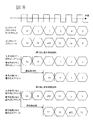
SOVA復号方式は,Claude Berrou et al, ”A Low Complexity Soft-Output Viterbi Decoder Architecture”, Proc.IEEE, 1993に示されている。図3にSOVA復号方式の動作概要の説明図を示す。畳込み符号器301は,符号器に信号が入力されるとタップの状態が遷移し,拘束長をKとすると2^(k-1)通りの状態が存在する。図3は,拘束長K=4の畳込み符号器301を示している。図3のタップの状態が,000,001,010,011,100,101,110,111となっているとき,それぞれ,State 0,State 1,State 2,State 3,State 4,State 5,State 6,State 7と定義する。State 6の状態で入力信号0が入力されると,次の状態はState 7となる。このState 6の時点をBit=(-1),State 7の時点をBit=0とすると,入力信号0によって,State 6からState 7へ状態が遷移したことになる。この状態遷移を逆にたどることによって,入力信号系列を求めることができる。状態遷移を逆にたどるトレースバックと呼ぶ。図3では,Bit=0でState 7,Bit=(-1)でState 6,Bit=(-2)でState 4というように,復号器に入力された信号からBit=(-63)までの信号系列に対して,状態遷移の可能性を調べ,最も確からしい最尤パスを追跡することによって,Bit=(-63)からBit=(-62)に状態遷移する際に入力された信号を硬判定値として出力する。
【0007】
また,図3において,Bit=(-2)からBit=(-1)での入力信号が誤っていた場合を想定すると,別の状態遷移の可能性があるため,最尤パスの追跡の他に,Bit=(-1)からBit=(-2)で別の状態遷移について調べ,これを競合パスとして追跡する。
【0008】
図3において,Bit=(-63)時点で前記最尤パスと競合パスに関して,それぞれのパスの確からしさの差分に相当する尤度情報を軟判定値として求める。
【0009】
SOVA復号化方式において,誤り訂正能力の特性を発揮するためにトレースバックするビット数L(トレースバック長)は,拘束長Kの数倍程度必要であることが知られている。図4に,1ビットの復号結果を得るために,最低限必要なトレースバック長の値をL_min=64とした場合を示す。従来の技術では,Bit=0からBit=(-63)までのトレースバックを1回行うと,Bit=(-63)時点における1ビット分の硬判定値と軟判定値が得られる。1ビット分の硬判定値と軟判定値を得るために,1回のトレースバックでL_minに相当する演算量が必要で,復号する情報ビット数をNとすると,L_min×Nの演算量が必要となる。
【0010】
【発明が解決しようとする課題】
従来の技術では,1回のSOVA復号結果を得るのに情報ビット数Nとトレースバック長L_minに比例して演算時間が大きくなるという問題がある。特に,ターボ復号処理では,復号出力を再度復号器に入力する繰り返し復号処理を行うため,伝送路の誤りが多い場合は,高い誤り訂正能力を実現するために繰り返し回数が多く必要とされる。繰り返し回数をITとするとトータルの演算量はIT×L_min×Nとなり,繰り返し回数が大きいほど演算時間が長くなり,信号処理に高い動作周波数が必要とされる。例えば,従来の技術によるハードウェア実装を行うと,伝送レート384kbit/secのターボ復号処理に必要な動作周波数は,繰り返し回数IT=16とすると,100MHzにもなる。移動端末の場合は特に低消費電力化が重要な課題であるため,動作周波数を低減させることが必要となる。
【0011】
そこで,本発明では,SOVA復号化方式におけるトレースバック処理の演算時間を削減することを目的とする。
【0012】
【課題を解決するための手段】
前記問題を解決するために,1回のトレースバックにおいて複数ビットの硬判定出力と軟判定値を求めるトレースバック処理方式を提供する。本発明のトレースバック回路の一実施例では,図5に示すように,トレースバックにおいて,最尤パスをたどる際に1ビットごとに最尤パス方向と反対に遷移するパスを競合パスとして記憶する。これにより,1回のトレースバックで競合パス全部について調べることができるため,各ビットにおける軟判定値を求めることが可能となる。従来の技術では,1回のトレースバックをLビット実行して軟判定値1ビット分を求めるが,本発明によればトレースバック開始点からの深さをMビットとすると,トレースバックをMビット実行して軟判定値1ビット分が求まる。トレースバック長が拘束長Kの数倍程度の最小値L_minを満たしていれば特性が保たれることになる。1回のトレースバックでLビット実行するとM>=L_minを満たすビットについて軟判定値が定まるため,L-L_minビット分の硬判定出力と軟判定値が1回のトレースバックで得られる。これにより,1回のトレースバックで複数ビットの復号結果が求められるため,情報長Nビット全部の復号結果を求めるためのトレースバック回数をN回からN/(L-L_min)回に減らすことが可能となり,演算時間を削減できる。
【0013】
【発明の実施の形態】
図6に本発明の復号器の一実施例を示す。この復号器は,復号器の入力として受信ターボ符号データを情報長分蓄える入力信号メモリ601と,軟判定ビタビアルゴリズムによるSOVA復号器602と,前記SOVA復号化による硬判定出力と軟判定値の復号結果を出力として格納する復号結果メモリ603と,前記復号データと軟判定情報を所定回数繰り返し演算させるときにインターリーブパターンによってアドレス制御を行う制御部604と,インタリーブパターンを格納したインタリーブパターンメモリ605とを備えている。インターリーブパターンによってアドレス制御を行う制御部604によって,繰り返し復号回数に応じてデータの流れが制御される。
【0014】
図7により,データの流れを説明する。繰り返し復号奇数回目の処理では,通信路を通って受信されたターボ符号化データを格納した入力信号メモリ601より,U'をアドレス順に読み出した値をSOVA復号器602入力のC0として,Y1'をアドレス順に読み出した値をC1として使用する。SOVA復号器602の出力L(U')_nは,事前尤度情報Le(U')_(n-1)と通信路値U'を減算した後,外部情報尤度Le(U')_n=β×{L(U')_n U' Le(U')_(n-1)}として復号結果メモリ603にアドレス順に書き込まれる。繰り返し復号の初回は,事前尤度情報Le(U')_(n-1)を0とする。ここでβは軟判定値に対する信頼度を重み付けする係数であり,誤り訂正能力の特性に影響を与える。このβは,誤り訂正能力のビットエラーレートから通信路のノイズ状態を測定し,適応的に制御することが可能なものである。なお,このβで重み付けする箇所は図6では省略されている。次に,繰り返し復号偶数回目の処理では,入力信号メモリ601より,インタリーバ701によってインタリーブパタンに従って読み出した値をSOVA復号器入力のC0として,Y2'をアドレス順に読み出した値をC1として使用する。ここでインタリーバ701の機能は,図6のインタリーブパタンメモリ605から制御部604によってインタリーブパタンを読み出すことによって,入力信号メモリ601に対するアドレスを生成することにより実現する。事前尤度情報Le(U')_(n-1)は,前回の復号で得られた外部情報尤度を復号結果メモリ603からインタリーバ702によってインタリーブパタンに従って読み出した値を使用する。インタリーバ702の機能もインタリーバ701と同様にして実現される。SOVA復号器602の出力L(U')_nは,事前尤度情報Le(U')_(n-1)と通信路値U'を減算した後,外部情報尤度Le(U')_n=β×{L(U')_n U' Le(U')_(n-1)}としてデインタリーバ703によって復号結果メモリ603にインタリーブパタンに従ったアドレスで書き込む。ここで,デインタリーバ703の機能も,インタリーバ701・702と同様にして実現される。つまり,図7におけるインタリーバ701・702とデインタリーバ703は,図6において制御部604とインタリーブパタンメモリ605で表されていることになる。遅延器606は,SOVA復号器602入力のC0とC2を加算したものを,SOVA復号器602の出力L(U')_nが求まるまで遅延させる回路であり,繰り返し復号最終回には0固定とする。
【0015】
次にインタリーバ701・702,デインタリーバ703の機能の実現方法に関して,図6の制御部604とインタリーブパタンメモリ605の繰り返し復号実行時の動作を,図8を用いて説明する。繰り返し復号奇数回時は,入力信号メモリの読み出しアドレス,復号結果メモリの読み出しアドレス,書き込みアドレスは1ずつインクリメントするアドレス順となるため,制御部604は信号処理のタイミングにあわせてアドレス生成を行う。繰り返し復号偶数回時は,インタリーブパタンメモリのアドレス順にインタリーブパタンを読み出した値を,入力信号メモリの読み出しアドレス,復号結果メモリの読み出しアドレス,書き込みアドレスとして使用する。制御部604で各メモリに対する信号処理タイミングにあわせてアドレスを生成する。
【0016】
次に,図6のSOVA復号器602について説明する。SOVA復号器602では,すべての状態遷移について遷移の確からしさ(メトリック値)と,遷移情報(パス値)と,ある状態に至るまでの遷移の確からしさの差分に相当する尤度情報(尤度値)とを求めるACS(Add-Compare-Select)回路607と,ACS回路607で求めたメトリック値を記憶するメトリックメモリ608と,パス値を記憶するパスメモリ102と,尤度値を記憶する尤度メモリ103と,パス値から最も確からしい遷移の軌跡を追跡するトレースバック回路101とを備えている。
【0017】
まずACS回路607における実施の形態の例を図9に示す。ACS回路607では,状態遷移の基本構造(バタフライ)に対し,遷移ブランチ毎にブランチの確からしさb_metをSOVA復号器入力のC0,C1,C2の関数として求める。この関数は,符号器の構成に応じた関数となる。例えば,3GPP Release'99のターボ符号器の仕様を例とした場合,次式(1)で表される。

【0018】
図6のメトリック値を格納したメトリックメモリ608より,メトリック値MET_P0,MET_P1をロードし,それぞれACS回路における入力側の二つの状態に対するメトリック値とする。ここで,メトリック値MET_P0,MET_P1は1ビット前にACS回路で計算されてメトリックメモリ608に格納されたメトリック値の内,ACS回路の入力側に対応する二つの状態に対応するメトリック値が選択されるものとする。図9では,状態0に対して入力信号0が入力された場合は状態0に遷移し,状態1に対して入力信号1が入力された場合は状態0に遷移する様子を表している。このとき,状態0に遷移する可能性としては,状態0から状態0への遷移と,状態1から状態0への遷移の二つの場合がある。状態0から状態0への遷移の確からしさAは,A=MET_P0+b_metで表され,状態1から状態0への遷移の確からしさBは,B=MET_P1-b_metで表される。この二つの遷移に対して遷移の確からしさを比較し,図9の例ではBの方がAよりも大きいため,状態1から状態0への遷移が確からしいことになる。同様にして状態4に対して遷移する可能性について調べると,図9では状態1から状態4への遷移が確からしいことになる。このように,図9では状態の遷移が確からしい道筋を太線で示してある。図9の場合,遷移の確からしさBの方がAよりも大きいため,パス値を1として定義する。逆にAの方が大きい場合は,パス値を0とする。同様にして,遷移の確からしさCとDを比較して,状態4に遷移するパス値をCがDよりも大きい場合は0とし,CがDより小さい場合は1とする。また,遷移の確からしさAとBの差分の絶対値を2で割った値を状態0の尤度値とし,同様にCとDの差分の絶対値を2で割った値を状態4の尤度値とする。ACS回路ですべての状態に対してメトリック値,パス値,尤度値を求め,それぞれメトリックメモリ608,パスメモリ102,尤度メモリ103に格納する。メトリック値の飽和を避けるため,1ビット前のACS回路処理で最大値をもつメトリック値を記憶しておき,各メトリック値から記憶したメトリック値を減算してからメトリックメモリ608に格納するようにするようにしてもよい。
【0019】
図1にトレースバック回路の実施例の説明図を示す。トレースバック回路101は,トレースバック開始信号TR_LDをトリガとしてトレースバック開始時状態TR_STを初期状態とし,パスメモリ102から読み出したパス値と尤度メモリ103の尤度値を使って,硬判定値SIGNと軟判定値WGTを求めるものである。ただし,ここでP[0]からP[7]は,それぞれ状態0から状態7までに対するパス値を表すものとする。
【0020】
トレースバック回路101は,状態数分のトレース部104と出力選択部105から構成される。トレース部104は,最も確からしい遷移を表す最尤パスフラグSFと,次に確からしい遷移を表す競合パスフラグCFと,最尤パスと競合パスの確からしさの差分を表す尤度情報Wを各状態について求める回路である。各トレース部104で求められた情報は,1ビット前の情報としてトレース部104にトレリス状態遷移に従ってフィードバックをかける構造になっている。例えば,図1ではBit=0の時点において,トレース部7で最尤パスフラグSF=1を求めている。この結果をBit=-1の時点においてトレース部7とトレース部6の入力としてフィードバックすることにより,トレース部7は競合パスフラグCF=1を,トレース部6は最尤パスフラグSF=1を求めている。このようにして,他のトレース部も同様な働きをすることによって,トレースバック処理が行われる。出力選択部105では,各状態のトレース部104の出力結果から,硬判定値SIGNと軟判定値WGTを計算する。
【0021】
図10にトレースバック回路のトレース部における最尤パスフラグSFを決定するアルゴリズムを示す。トレースバック開始時は,ACS回路で最もメトリック値の大きい状態をトレースバック開始時状態TR_STとし,状態TR_STに対応するトレース部の最尤パスフラグSFが1となるようにフラグを設定する。トレースバック処理中においては,1ビット前時点で最尤パスフラグSFが1であった状態から自状態に遷移してくるパスが,パスメモリから読み出したパス値と比べて正しい遷移を示していれば,自状態が最尤パスとして継承され,最尤パスフラグSFが1となる。
【0022】
図11にトレースバック回路のトレース部における競合パスフラグCFを決定するアルゴリズムを示す。トレースバック開始時は,全状態について競合パスは存在しないため,競合パスフラグCFを0にリセットする。また,自状態が最尤パスである場合には,競合パスとなり得ないので競合パスフラグCFは0になる。競合パスになる条件として,1ビット前において最尤パスであった状態から自状態に遷移するパスについて,パスメモリから読み出したパス値と比べて正しくない場合に,競合パスフラグCFが1となる。また,1ビット前において競合パスであった状態から自状態に遷移するパスについて,パスメモリから読み出したパス値と比べて正しい場合に,競合パスが継承されることになり,競合パスフラグCFが1となる。
【0023】
図12にトレースバック回路のトレース部における尤度情報Wを決定するアルゴリズムを示す。まずトレースバック開始時は,尤度情報を最大値に設定する。また,自状態が最尤パスである場合も尤度情報を最大値に設定する。1ビット前において最尤パスであった状態から自状態に遷移するパスが,パスメモリから読み出したパス値と比べて正しくない場合には,最尤パスであった状態の尤度メモリから読み出した尤度値DELTAを尤度情報の候補W_1=DELTAとして保持する。1ビット前において競合パスであった状態から自状態に遷移するパスが,パスメモリから読み出したパス値と比べて正しい場合は,競合パスの状態における1ビット前の尤度情報W(1bit前)を尤度情報の候補W_2=W(1bit前)として保持する。尤度情報の候補W_1,W_2を比較して小さい値を自状態における尤度情報W=Min(W_1,W_2)として出力する。
【0024】
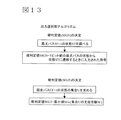
図13にトレースバック回路の出力選択部のアルゴリズムを示す。硬判定値SIGNを求めるためには,最尤パスフラグSF=1である状態STを選択し,1ビット前の最尤パスの状態から状態STに遷移する際に符号器で入力された符号を硬判定SIGNとして出力する。パス値を符号器で入力された符号とすれば,状態STにおけるパス値が硬判定値SIGNとして出力される。次に軟判定値WGTを求めるために,競合パスフラグCF=1である状態の集合Uを求める。集合Uに属するトレース部の尤度情報Wの最小値を軟判定値WGTとして出力する。
【0025】
【発明の効果】
本発明によれば,情報長Nビットの復号を行う場合のトレースバックの演算量は,次式(2)のようにあらわすことができる。
[(N+L-L_min-1)/(L-L_min)]×L×S (2)
ただし,[x]はxを超えない最大の整数を表すものとする。Lは1回のトレースバックを行うビット数で,L_minはSOVA復号結果の軟判定値の信頼性を確保するために最低限必要なトレースバックのビット数を表す。また,Sは状態数を表し,トレース部の個数に相当する。従来の技術によるトレースバックの演算量は,次式(3)で表される。
N×L_min×2 (3)
ここで,最尤パスと競合パスの二つに対する演算量を考慮して,2倍している。
【0026】
図14に従来の技術と本発明の演算量比較を,N=512, L=64, L_min=32の場合を例として示す。状態数が32よりも小さい範囲では,本発明は従来の技術に比べて演算量が少なくて済むことがわかる。拘束長Kが小さく,状態数が少ない場合に,本発明が有効であると言える。
【0027】
本発明により,拘束長Kが小さく状態数が少ないターボ符号において,ターボ復号器におけるSOVA復号の演算量が低減され,信号処理に必要とされるディジタル信号処理の動作周波数が低減できるという効果がある。例えば,従来の技術に比べて約1.4倍の49kGateのハードウェア実装で,伝送レート384kbit/secのターボ復号処理に必要な動作周波数は繰り返し回数IT=16として,12MHz程度となり,従来の技術の約1/8程度に抑えることができる。
【図面の簡単な説明】
【図1】本発明におけるターボ復号方式実施例のトレースバック回路の説明図。
【図2】ターボ符号を用いた通信システムの説明図。
【図3】ターボ復号におけるトレースバックの説明図。
【図4】従来技術におけるトレースバックの問題点の説明図。
【図5】本発明におけるトレースバック方式の説明図。
【図6】本発明におけるターボ復号器の構成図。
【図7】本発明におけるターボ繰り返し復号時の動作説明図。
【図8】本発明におけるターボ復号器制御部の動作説明図。
【図9】本発明におけるターボ復号器ACS回路の説明図。
【図10】トレースバック回路における最尤パスフラグ決定アルゴリズム。
【図11】トレースバック回路における競合パスフラグ決定アルゴリズム。
【図12】トレースバック回路における尤度情報決定アルゴリズム。
【図13】トレースバック回路における硬判定値・軟判定値決定アルゴリズム。
【図14】従来の復号処理と本発明の復号処理との演算量を比較したグラフ。
【符号の説明】
101・・・トレースバック回路,102・・・パスメモリ,103・・・尤度メモリ,104・・・トレース部,105・・・出力選択部,201・・・ターボ符号器,202・・・通信路,203・・・ターボ復号器,204,206・・・再帰的組織畳込み符号器,205,208,211・・・インタリーバ,207,209・・・復号器,210・・・デインタリーバ,301・・・畳込み符号器,601・・・入力信号メモリ,602・・・SOVA復号器,603・・・復号結果メモリ,604・・・制御部,605・・・インタリーブパタンメモリ,606・・・遅延器,607・・・ACS回路,608・・・メトリックメモリ3,701,702・・・インタリーバ,703・・・デインタリーバ。[0001]
BACKGROUND OF THE INVENTION
The present invention relates to an error correction decoder that corrects and decodes transmission errors in received encoded data, and more particularly to an error correction decoder of a turbo code system.
[0002]
[Prior art]
In a communication system, various error correction coding schemes are employed to relieve data transmission errors. For example, Yamaguchi, et al., “New encoding method approaching the Shannon limit“ turbo code ”, Nikkei Electronics, July 13, 1998, No.721, pp.163-177 A turbo coding method is known as a high coding method. In the communication system shown in FIG. 2, two recursive systematic convolutional encoders are prepared in the
[0003]
The turbo decoder 203 includes decoders (D1, D2) 207 and 209,
[0004]
Decoding methods of the decoders (D1, D2) include, for example, a MAP (maximum posterior probability) decoding method and a SOVA (soft decision Viterbi algorithm) decoding method. The former MAP decoding method calculates the forward probability a and the backward probability b using the transition probability of the received data, and uses the forward probability a and backward probability b for each time (bit). The one having the greater probability of being “1” or “0” (hard decision decoded data) and the difference (soft decision value) are obtained.
[0005]
Compared to the MAP decoding method, the SOVA decoding method is known to have a smaller amount of calculation, although the error correction characteristics deteriorate.
[0006]
The SOVA decoding scheme is shown in Claude Berrou et al, “A Low Complexity Soft-Output Viterbi Decoder Architecture”, Proc. IEEE, 1993. FIG. 3 is an explanatory diagram of an outline of the operation of the SOVA decoding method. In the convolutional encoder 301, when a signal is input to the encoder, the tap state transitions, and when the constraint length is K, there are 2 ^ (k-1) states. FIG. 3 shows a convolutional encoder 301 with a constraint length K = 4. When the tap states in FIG. 3 are 000, 001, 010, 011, 100, 101, 110, 111,
[0007]
In FIG. 3, assuming that the input signal from Bit = (-2) to Bit = (-1) is incorrect, there is a possibility of another state transition. Then, another state transition is examined from Bit = (-1) to Bit = (-2), and this is traced as a competitive path.
[0008]
In FIG. 3, regarding the maximum likelihood path and the competitive path at the time of Bit = (− 63), likelihood information corresponding to the difference in the probability of each path is obtained as a soft decision value.
[0009]
In the SOVA decoding method, it is known that the number of bits L (trace back length) to be traced back in order to exhibit the error correction capability characteristics needs to be several times the constraint length K. FIG. 4 shows a case where the minimum traceback length value required to obtain a 1-bit decoding result is L_min = 64. In the conventional technique, when trace back from Bit = 0 to Bit = (− 63) is performed once, a hard decision value and a soft decision value for one bit at the time of Bit = (− 63) are obtained. In order to obtain a hard decision value and soft decision value for one bit, an amount of computation equivalent to L_min is required in one traceback, and if the number of information bits to be decoded is N, an amount of computation of L_min × N is necessary. It becomes.
[0010]
[Problems to be solved by the invention]
The conventional technique has a problem that the calculation time increases in proportion to the number of information bits N and the traceback length L_min to obtain one SOVA decoding result. In particular, in the turbo decoding process, iterative decoding is performed by inputting the decoded output to the decoder again. Therefore, if there are many errors in the transmission path, a large number of iterations are required to realize high error correction capability. If the number of iterations is IT, the total computation amount is IT x L_min x N. The larger the number of iterations, the longer the computation time, and a higher operating frequency is required for signal processing. For example, when hardware is implemented using conventional technology, the operating frequency required for turbo decoding at a transmission rate of 384 kbit / sec is 100 MHz if the iteration count IT = 16. In the case of a mobile terminal, it is particularly important to reduce power consumption, so it is necessary to reduce the operating frequency.
[0011]
Accordingly, an object of the present invention is to reduce the calculation time of the traceback process in the SOVA decoding method.
[0012]
[Means for Solving the Problems]
In order to solve the above problem, a traceback processing method for obtaining a hard decision output and a soft decision value of a plurality of bits in one traceback is provided. In one embodiment of the traceback circuit of the present invention, as shown in FIG. 5, when tracing the maximum likelihood path, a path that transitions in the opposite direction to the maximum likelihood path direction is stored as a competing path in the traceback. . As a result, since all the competing paths can be examined by one traceback, it is possible to obtain a soft decision value for each bit. In the conventional technology, one bit of traceback is executed to obtain 1 bit of the soft decision value. According to the present invention, if the depth from the traceback start point is M bits, the traceback is set to M bits. This is executed to obtain a soft decision value of 1 bit. If the traceback length satisfies a minimum value L_min that is several times the constraint length K, the characteristics are maintained. When the L bit is executed in one traceback, the soft decision value is determined for the bit satisfying M> = L_min. Therefore, the hard decision output and the soft decision value for L-L_min bits can be obtained by one traceback. As a result, a multi-bit decoding result is obtained in one traceback, so the number of tracebacks for obtaining the decoding result of all N bits of information length can be reduced from N times to N / (L-L_min) times. This makes it possible to reduce computation time.
[0013]
DETAILED DESCRIPTION OF THE INVENTION
FIG. 6 shows an embodiment of the decoder of the present invention. This decoder has an
[0014]
The data flow will be described with reference to FIG. In the iterative decoding odd-numbered processing, the value obtained by reading U ′ in the order of addresses from the
[0015]
Next, regarding the method of realizing the functions of the
[0016]
Next, the
[0017]
First, an example of an embodiment in the
[0018]
The metric values MET_P0 and MET_P1 are loaded from the
[0019]
FIG. 1 is an explanatory diagram of an embodiment of the traceback circuit. The
[0020]
The
[0021]
FIG. 10 shows an algorithm for determining the maximum likelihood path flag SF in the trace portion of the traceback circuit. At the start of traceback, the ACS circuit has the largest metric value as the traceback start state TR_ST, and the flag is set so that the maximum likelihood path flag SF of the trace unit corresponding to the state TR_ST is 1. During the traceback process, if the path transitioning from the state where the maximum likelihood path flag SF is 1 at the time of 1 bit to the own state shows a correct transition compared to the path value read from the path memory The own state is inherited as the maximum likelihood path, and the maximum likelihood path flag SF becomes 1.
[0022]
FIG. 11 shows an algorithm for determining the contention path flag CF in the trace portion of the traceback circuit. At the start of traceback, there is no contention path for all states, so the contention path flag CF is reset to 0. Further, when the own state is the maximum likelihood path, the contention path flag CF becomes 0 because it cannot be a contention path. As a condition for becoming a competing path, the competing path flag CF is set to 1 when the path transitioning from the state that was the most likely path one bit before is not correct compared to the path value read from the path memory. In addition, when the path that has been changed from the contention path one bit before to the current state is correct compared to the path value read from the path memory, the contention path is inherited, and the contention path flag CF is set to 1. It becomes.
[0023]
FIG. 12 shows an algorithm for determining likelihood information W in the trace portion of the traceback circuit. First, at the start of traceback, the likelihood information is set to the maximum value. The likelihood information is also set to the maximum value even when the own state is the maximum likelihood path. If the path transitioning from the state that was the most likely path one bit before is not correct compared to the path value read from the path memory, the path was read from the likelihood memory in the state that was the most likely path. The likelihood value DELTA is held as likelihood information candidate W_1 = DELTA. If the path that transitions from the contention path one bit before to its own state is correct compared to the path value read from the path memory, the likelihood information W one bit before in the contention path state (1 bit before) Is stored as likelihood information candidate W_2 = W (1 bit before). Likelihood information candidates W_1 and W_2 are compared, and a small value is output as likelihood information W = Min (W_1, W_2) in its own state.
[0024]
FIG. 13 shows an algorithm of the output selection unit of the traceback circuit. In order to obtain the hard decision value SIGN, the state ST with the maximum likelihood path flag SF = 1 is selected, and the code input by the encoder at the time of transition from the state of the maximum likelihood path one bit before to the state ST is hard. Output as judgment SIGN. If the pass value is the code input by the encoder, the pass value in the state ST is output as the hard decision value SIGN. Next, in order to obtain the soft decision value WGT, a set U in a state where the contention path flag CF = 1 is obtained. The minimum value of the likelihood information W of the trace units belonging to the set U is output as the soft decision value WGT.
[0025]
【The invention's effect】
According to the present invention, the amount of calculation of traceback when decoding information length N bits can be expressed as the following equation (2).
[(N + L-L_min-1) / (L-L_min)] × L × S (2)
However, [x] represents the largest integer not exceeding x. L is the number of bits to be traced once, and L_min is the minimum number of bits of traceback necessary to ensure the reliability of the soft decision value of the SOVA decoding result. S represents the number of states and corresponds to the number of trace parts. The calculation amount of the trace back according to the conventional technique is expressed by the following equation (3).
N × L_min × 2 (3)
Here, the calculation amount for the maximum likelihood path and the competing path is taken into consideration, and is doubled.
[0026]
FIG. 14 shows a comparison of the amount of calculation between the conventional technique and the present invention, taking N = 512, L = 64, and L_min = 32 as an example. In the range where the number of states is smaller than 32, it can be seen that the present invention requires less calculation amount than the conventional technique. It can be said that the present invention is effective when the constraint length K is small and the number of states is small.
[0027]
According to the present invention, in a turbo code with a small constraint length K and a small number of states, the amount of SOVA decoding in the turbo decoder is reduced, and the operating frequency of digital signal processing required for signal processing can be reduced. . For example, with a 49kGate hardware implementation approximately 1.4 times that of the conventional technology, the operating frequency required for turbo decoding with a transmission rate of 384 kbit / sec is about 12 MHz, with the iteration count IT = 16. It can be reduced to about 1/8.
[Brief description of the drawings]
FIG. 1 is an explanatory diagram of a traceback circuit according to an embodiment of a turbo decoding system of the present invention.
FIG. 2 is an explanatory diagram of a communication system using a turbo code.
FIG. 3 is an explanatory diagram of traceback in turbo decoding.
FIG. 4 is an explanatory diagram of problems with traceback in the prior art.
FIG. 5 is an explanatory diagram of a traceback method in the present invention.
FIG. 6 is a configuration diagram of a turbo decoder according to the present invention.
FIG. 7 is an explanatory diagram of operations during turbo iterative decoding in the present invention.
FIG. 8 is an operation explanatory diagram of a turbo decoder control unit in the present invention.
FIG. 9 is an explanatory diagram of a turbo decoder ACS circuit according to the present invention.
FIG. 10 shows a maximum likelihood path flag determination algorithm in a traceback circuit.
FIG. 11 shows a competitive path flag determination algorithm in the traceback circuit.
FIG. 12 shows a likelihood information determination algorithm in the traceback circuit.
FIG. 13 is a hard decision value / soft decision value determination algorithm in a traceback circuit;
FIG. 14 is a graph comparing the amount of calculation between the conventional decoding process and the decoding process of the present invention.
[Explanation of symbols]
DESCRIPTION OF
Claims (4)
前記SOVA復号器は,前記ターボ符号器のタップの状態遷移をトレースバックするトレースバック処理部を有し,前記トレースバック処理部は,最も確からしい状態遷移を表す最尤パスであるかどうかを示す最尤パスフラグと,次に確からしい状態遷移を表す競合パスであるかどうかを示す競合パスフラグと,最尤パスと競合パスとの確からしさの差分に相当する尤度情報とを計算して,1ビットトレースバックする毎に硬判定値と軟判定値を確定する誤り訂正復号器。There are several states of taps, an error correction with a decoder which performs a signal coded soft decision Viterbi algorithm data (SOVA) decoding in a turbo sign-instrument state of the tap changes every time one bit input A decoder comprising:
The SOVA decoder has a traceback processor for tracing back the state transition of the tap of the turbo mark-decoder, whether the traceback processing unit is a maximum likelihood path representing the most probable state transition A maximum likelihood path flag to indicate, a competitive path flag indicating whether or not it is a competitive path representing the next most likely state transition, and likelihood information corresponding to the difference in the likelihood between the maximum likelihood path and the competitive path, An error correction decoder that determines a hard decision value and a soft decision value every time one bit is traced back.
前記トレースバック処理部は,1ビットトレースバックする毎に最尤パスから最尤パスに遷移する際に前記ターボ符号器に入力された符号を硬判定値として出力し,競合パスの集合を求め,これらの競合パスの内で前記尤度情報の最小値を軟判定値として出力することを特徴とする誤り訂正復号器。The error correction decoder according to claim 1,
The traceback processing unit outputs, as a hard decision value, a code input to the turbo encoder when transitioning from the maximum likelihood path to the maximum likelihood path every time 1-bit traceback is performed, and obtains a set of competing paths, An error correction decoder characterized by outputting a minimum value of the likelihood information as a soft decision value among these competing paths.
前記トレースバック処理部は,前記タップの状態数分のトレースバック計算モジュールを有し,各計算モジュールは,前記最尤パスフラグと,前記競合パスフラグと,前記尤度情報とを計算することを特徴とする誤り訂正復号器。The error correction decoder according to claim 1 or 2,
The traceback processing unit has traceback calculation modules for the number of tap states, and each calculation module calculates the maximum likelihood path flag, the competitive path flag, and the likelihood information. Error correction decoder.
Priority Applications (1)
| Application Number | Priority Date | Filing Date | Title |
|---|---|---|---|
| JP2001008435A JP3823731B2 (en) | 2001-01-17 | 2001-01-17 | Error correction decoder |
Applications Claiming Priority (1)
| Application Number | Priority Date | Filing Date | Title |
|---|---|---|---|
| JP2001008435A JP3823731B2 (en) | 2001-01-17 | 2001-01-17 | Error correction decoder |
Related Child Applications (1)
| Application Number | Title | Priority Date | Filing Date |
|---|---|---|---|
| JP2004320035A Division JP2005102274A (en) | 2004-11-04 | 2004-11-04 | Error correction decoder |
Publications (3)
| Publication Number | Publication Date |
|---|---|
| JP2002217748A JP2002217748A (en) | 2002-08-02 |
| JP2002217748A5 JP2002217748A5 (en) | 2005-05-19 |
| JP3823731B2 true JP3823731B2 (en) | 2006-09-20 |
Family
ID=18876053
Family Applications (1)
| Application Number | Title | Priority Date | Filing Date |
|---|---|---|---|
| JP2001008435A Expired - Fee Related JP3823731B2 (en) | 2001-01-17 | 2001-01-17 | Error correction decoder |
Country Status (1)
| Country | Link |
|---|---|
| JP (1) | JP3823731B2 (en) |
Families Citing this family (7)
| Publication number | Priority date | Publication date | Assignee | Title |
|---|---|---|---|---|
| JP3732830B2 (en) | 2002-10-10 | 2006-01-11 | 松下電器産業株式会社 | Multicarrier transmission apparatus and multicarrier transmission method |
| EP1503535A4 (en) | 2002-10-31 | 2011-07-06 | Panasonic Corp | Transmitting device and transmitting method |
| JP4011583B2 (en) | 2003-01-30 | 2007-11-21 | 富士通株式会社 | Data recording / reproducing system and method |
| US7246298B2 (en) | 2003-11-24 | 2007-07-17 | Via Technologies, Inc. | Unified viterbi/turbo decoder for mobile communication systems |
| JP4432781B2 (en) * | 2005-01-17 | 2010-03-17 | 株式会社日立製作所 | Error correction decoder |
| JP5116677B2 (en) * | 2006-08-22 | 2013-01-09 | パナソニック株式会社 | Soft output decoder, iterative decoding device, and soft decision value calculation method |
| CN103250385B (en) * | 2010-11-26 | 2015-07-15 | 三菱电机株式会社 | Soft decision value generation circuit |
-
2001
- 2001-01-17 JP JP2001008435A patent/JP3823731B2/en not_active Expired - Fee Related
Also Published As
| Publication number | Publication date |
|---|---|
| JP2002217748A (en) | 2002-08-02 |
Similar Documents
| Publication | Publication Date | Title |
|---|---|---|
| JP4432781B2 (en) | Error correction decoder | |
| US7584409B2 (en) | Method and device for alternately decoding data in forward and reverse directions | |
| US6445755B1 (en) | Two-step soft output viterbi algorithm decoder using modified trace back | |
| JP3730885B2 (en) | Error correction turbo code decoder | |
| JP2007510337A (en) | Viterbi / Turbo integrated decoder for mobile communication systems | |
| US20130007568A1 (en) | Error correcting code decoding device, error correcting code decoding method and error correcting code decoding program | |
| JP3823731B2 (en) | Error correction decoder | |
| JP3540224B2 (en) | Turbo decoder, turbo decoding method, and storage medium storing the method | |
| KR19990081470A (en) | Method of terminating iterative decoding of turbo decoder and its decoder | |
| US8489972B2 (en) | Decoding method and decoding device | |
| US7584407B2 (en) | Decoder and method for performing decoding operation using map algorithm in mobile communication system | |
| CN106209117B (en) | Low-resource-consumption multi-parameter configurable Viterbi decoder | |
| JP2002076921A (en) | Method and apparatus for error correction code decoding | |
| JP2005102274A (en) | Error correction decoder | |
| JP5370487B2 (en) | Decoding method and decoding apparatus | |
| JP4295871B2 (en) | Error correction decoder | |
| KR20010113792A (en) | Method and apparatus for decoding recursive convolutional symbols | |
| JP4525658B2 (en) | Error correction code decoding apparatus | |
| KR100317377B1 (en) | Encoding and decoding apparatus for modulation and demodulation system | |
| Gnanamurugan et al. | Vlsi Implementation of Low Power Convolutional Coding With Viterbi Decoding Using Fsm | |
| JP2006280010A (en) | Decoding device and decoding method | |
| JP2006314055A (en) | Turbo decoding method and apparatus |
Legal Events
| Date | Code | Title | Description |
|---|---|---|---|
| A521 | Written amendment |
Free format text: JAPANESE INTERMEDIATE CODE: A523 Effective date: 20040720 |
|
| A621 | Written request for application examination |
Free format text: JAPANESE INTERMEDIATE CODE: A621 Effective date: 20040720 |
|
| RD01 | Notification of change of attorney |
Free format text: JAPANESE INTERMEDIATE CODE: A7421 Effective date: 20060418 |
|
| TRDD | Decision of grant or rejection written | ||
| A01 | Written decision to grant a patent or to grant a registration (utility model) |
Free format text: JAPANESE INTERMEDIATE CODE: A01 Effective date: 20060606 |
|
| A61 | First payment of annual fees (during grant procedure) |
Free format text: JAPANESE INTERMEDIATE CODE: A61 Effective date: 20060619 |
|
| FPAY | Renewal fee payment (event date is renewal date of database) |
Free format text: PAYMENT UNTIL: 20090707 Year of fee payment: 3 |
|
| FPAY | Renewal fee payment (event date is renewal date of database) |
Free format text: PAYMENT UNTIL: 20100707 Year of fee payment: 4 |
|
| FPAY | Renewal fee payment (event date is renewal date of database) |
Free format text: PAYMENT UNTIL: 20100707 Year of fee payment: 4 |
|
| FPAY | Renewal fee payment (event date is renewal date of database) |
Free format text: PAYMENT UNTIL: 20110707 Year of fee payment: 5 |
|
| FPAY | Renewal fee payment (event date is renewal date of database) |
Free format text: PAYMENT UNTIL: 20110707 Year of fee payment: 5 |
|
| FPAY | Renewal fee payment (event date is renewal date of database) |
Free format text: PAYMENT UNTIL: 20120707 Year of fee payment: 6 |
|
| FPAY | Renewal fee payment (event date is renewal date of database) |
Free format text: PAYMENT UNTIL: 20130707 Year of fee payment: 7 |
|
| LAPS | Cancellation because of no payment of annual fees |