JP3821520B2 - Hand dryer - Google Patents
Hand dryer Download PDFInfo
- Publication number
- JP3821520B2 JP3821520B2 JP25411896A JP25411896A JP3821520B2 JP 3821520 B2 JP3821520 B2 JP 3821520B2 JP 25411896 A JP25411896 A JP 25411896A JP 25411896 A JP25411896 A JP 25411896A JP 3821520 B2 JP3821520 B2 JP 3821520B2
- Authority
- JP
- Japan
- Prior art keywords
- drain hole
- water
- water receiving
- hole
- lid
- Prior art date
- Legal status (The legal status is an assumption and is not a legal conclusion. Google has not performed a legal analysis and makes no representation as to the accuracy of the status listed.)
- Expired - Fee Related
Links
Images


Description
【0001】
【発明の属する技術分野】
本発明は、洗面所やトイレ等にて手を洗い、濡れた手を温風にて乾燥させる手乾燥装置に関するものである。
【0002】
【従来の技術】
従来、この種の手乾燥装置では、トイレを使用した後や汚れた手を洗った後、ハンカチやタオルを使用せず、またハンカチなどを収納しているポケットを濡らすことなく、手を乾燥させる送風式の手乾燥装置が実用に供されている。
【0003】
この手乾燥装置は、送風手段と発熱手段を内蔵し、手検出手段で、差し出された手を検出したとき運転を開始し、濡れている手の表面を温風により乾燥させている。このとき水滴が飛散して壁、床、衣服を濡らすため、その防止対策として、送風吹出ノズルの下方に水滴を受ける水受け皿を配置させ、この水受け皿の一部に水抜き穴を形成し、連続的に使用した際の水受け皿に溜まる水滴を、前記水抜き穴から水抜きしている。また排水口が近くにない場合は、水受け皿の下に水受けカップを設けて貯水し、満水になると水受けカップを外して排水するものであった。
【0004】
【発明が解決しようとする課題】
このような従来の手乾燥装置においては、送風吹出ノズルから送風される風が、前記水抜き穴を通過して侵入するときに、騒音が異常に高くなるという課題があり、水抜き穴より騒音が発生しない手乾燥装置が求められている。
【0005】
また、水抜き穴を通過して侵入した風が、水受けカップに溜まった水の表面に直接吹きつけられるため、水面が波立って水がこぼれるという課題があり、水のこぼれない手乾燥装置の構成が求められている。
【0006】
本発明は、このような従来の課題を解決するもので、水抜き穴より発生する騒音を低減し、水抜き穴から温風が侵入しても水受けカップの水がこぼれることのない手乾燥装置を提供することを目的としている。
【0007】
【課題を解決するための手段】
本発明の手乾燥装置は上記目的を達成するために、本体内に収納された送風手段および発熱手段と、前記本体の下部に設けた送風吹出ノズルと、この送風吹出ノズルの下方に乾燥空間を介して設けた水受け皿と、この水受け皿に形成した水抜き穴とこの水抜き穴の下部に形成した筒部と、この水抜き穴の下方に着脱可能に設けた水受けカップを有し、前記水抜き穴を一体に形成した手乾燥装置であって、前記水受けカップの上面を覆う蓋と、蓋に設けた流入穴が水受け皿の水抜き穴の直下を外した位置に設けられ、かつ、水受け皿の水抜き穴の直下から、流入穴にかけて、水抜き穴から流下する水滴を水抜き穴に案内するように傾斜溝が蓋に設けられている構成を特徴としたものであり、騒音が異常に上昇することがなく、水受けカップに溜まった水がこぼれることのない手乾燥装置を得ることができる。
【0009】
【発明の実施の形態】
本発明は、本体内に収納された送風手段および発熱手段と、前記本体の下部に設けた送風吹出ノズルと、この送風吹出ノズルの下方に乾燥空間を介して設けた水受け皿と、この水受け皿に形成した水抜き穴とこの水抜き穴の下部に形成した筒部と、この水抜き穴の下方に着脱可能に設けた水受けカップを有し、前記水抜き穴を一体に形成した手乾燥装置であって、前記水受けカップの上面を覆う蓋と、蓋に設けた流入穴が水受け皿の水抜き穴の直下を外した位置に設けられ、かつ、水受け皿の水抜き穴の直下から、流入穴にかけて、水抜き穴から流下する水滴を水抜き穴に案内するように傾斜溝が蓋に設けられている構成を特徴としたものであり、この筒部は送風吹出ノズルより送風される勢いの強い温風が、水受け皿の水抜き穴から水受けカップへと流れるときに急拡散するのを防いで笛音の発生を少なく抑え、さらに水受けカップ内で共鳴した騒音が水抜き穴から外方へ拡散するのを防止し、また、水抜き穴を通過して侵入した風が、水受けカップに溜まった水の表面に直接吹きつけられて波立つのを防止でき、水受けカップから水がこぼれるのを防ぐという作用を有する。
【0011】
以下本発明の実施例について、図面を参照しながら説明する。
【0012】
【実施例】
図1〜図3に示すように、壁面に固定された本体1は、フロントケース2および下部に突設した水受け皿3で構成され、フロントケース2と水受け皿3の間に乾燥空間2aを形成している。フロントケース2内には送風手段4、発熱手段5および制御手段8を設け、フロントケース2の下端部には送風吹出ノズル6を乾燥空間2aおよび水受け皿3に向けて設置している。送風吹出ノズル6の近傍には乾燥空間2a内に差し出した手を検知する検知手段7を設け、前記制御手段8は検知手段7の検知信号を受けて送風手段4および発熱手段5を駆動制御している。
【0013】
送風手段4はモータ9aにより回転駆動されるブロワー9bを備え、この送風手段4と送風吹出ノズル6との間には発熱手段5としてPTCヒータ5a,5bを配設している。PTCヒータ5a,5bと並列にバイパス風路10を併設した発熱体収納枠11を設け、下流側には送風吹出ノズル6を連通して設けている。
【0014】
水受け皿3は、水滴を受けるために凹部を有するように皿状に形成され、この凹部の最底部には水抜き用の水抜き穴12が設けられ、水抜き穴12の下部に筒部13が形成されている。水受けカップ14は水抜き穴12の下に位置し、水受け皿3に着脱可能に取り付けられている。なお、本体1は取付金具15をねじ等の固定具16にて洗面所等の壁面に固定され、本体1の後部側には下方に吸気口17を有する吸気通路18が形成され、送風手段4の空気吸込部分となる。
【0015】
また、本体1から発生する騒音を下げるため、送風手段4の周囲には吸音材19が設けられている。
【0016】
上記構成において、まず送風吹出ノズル6の下方に手が差し込まれると、検知手段7が手を検知してその検知出力がオンとなり、制御手段8を介して送風手段4と発熱手段5を動作させて、送風吹出ノズル6より温風を送風する。温風の一部は、水抜き穴12を通過して水受けカップ14の方へ侵入するが、水抜き穴12に筒部13がない場合は、侵入した風は勢いが強いため、水抜き穴12から急に吐出拡散して笛音が発生しやすく、また、この音が水受け皿3内にこもった時に発生する共鳴音とが、水抜き穴12の周辺で合成されて大きな騒音となるものである。しかし、水抜き穴12の下方に筒部13を形成しているので、この筒部13の働きにより、笛音の発生や共鳴音の放散を抑えることができる。この騒音の大きさは、水抜き穴12の穴径に比例して大きくなり、筒部13の長さに比例して小さくなるという特性を有している。
【0017】
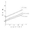
すなわち、水抜き穴12の穴径をd、筒部13の長さをhとすると、水抜き穴12の穴径dと手乾燥装置の騒音(dB)との関係はパラメータを筒長比h/dとして図4の特性図で示され、水抜き穴12の穴径dが大きいほど騒音は大きくなる。また特性曲線(イ)は筒部13を設けていない場合を示し、筒長比h/d=0.5の特性曲線(ロ)は特性曲線(イ)に対して約3dB低減し、筒長比h/d=1の特性曲線(ハ)は約4dB低減することがわかる。
【0018】
また、図5は筒長比h/dに対する騒音(dB)の関係を示す特性図であり、筒長比h/dが大きいほど騒音は小さくなるが、筒長比h/dが1以上ではその差はほとんどなくなる。
【0019】
したがって水抜き穴12の下部にこの穴と同一径の筒部13を形成することにより、笛音や共鳴音などの騒音を低減し、さらに筒長比をh/d=0.5以上とすることにより、騒音の低減効果をより大きくすることができる。
【0021】
水受けカップ14の上面を覆う蓋20を設け、この蓋20に開孔する流入穴21を、水受け皿3の水抜き穴12の直下を外した位置に設けている。さらに水抜き穴12から流下する水滴を流入穴21に案内する傾斜溝22を蓋20に形成している。
【0022】
上記構成において、手を乾燥するときは、水受け皿3に付着した水滴は水抜き穴12を流下し、水受けカップ14の蓋20に形成した傾斜溝22に沿って流れ、流入穴21から水受けカップ14に貯えることができる。
【0023】
また送風吹出ノズル6より吹き出された温風の一部は、水抜き穴12を通過して水受けカップ14の方へ侵入するが、水抜き穴12の直下には水受けカップ14を覆う蓋20があり、流入穴21は直下を外した位置に設けてあるため、侵入した風は蓋20に沿って拡散するのみで、水受けカップ14内の水表面に直接吹きつけることがない。したがって水受けカップ14に溜まった水の波立ちを防止し、周囲にこぼれるのを防止することができる。
【0024】
【発明の効果】
以上の実施例から明らかなように、本発明の手乾燥装置は、水受け皿に設けた水抜き穴の下方に同一内径の筒部を一体に形成し、水受けカップの上面を覆う蓋を設け、この蓋に開孔する流入穴を水受け皿の水抜き穴の直下を外して設けることにより、送風吹出ノズルから送風される風が前記水抜き穴を通過して侵入するときに発生しやすい騒音を抑制することができ、また、水抜き穴を通過して侵入した風が、水受けカップに溜まった水の表面に直接吹きつけられるのを防止できるため、水受けカップから水がこぼれるのを防ぐことができるという効果のある手乾燥装置を提供できる。
【図面の簡単な説明】
【図1】 (a)本発明の実施例の手乾燥装置を示す側断面図
(b)同水受けカップおよび蓋の外観斜視図
【図2】 同外観斜視図
【図3】 同A部詳細図
【図4】 同水抜き穴径と騒音との関係を示す特性図
【図5】 同筒長比と騒音との関係を示す特性図
【符号の説明】
1 本体
2a 乾燥空間
3 水受け皿
4 送風手段
5 発熱手段
6 送風吹出ノズル
12 水抜き穴
13 筒部
14 水受けカップ
20 蓋
21 流入穴[0001]
BACKGROUND OF THE INVENTION
The present invention relates to a hand drying apparatus for washing hands in a washroom or a toilet and drying wet hands with warm air.
[0002]
[Prior art]
Conventionally, with this type of hand drying device, after using the toilet or washing dirty hands, do not use handkerchiefs or towels, and do not wet the pockets that store handkerchiefs, etc., and dry the hands Air blow type hand dryers are in practical use.
[0003]
This hand-drying device has a built-in air blowing means and a heat-generating means, and starts operation when the hand detection means detects the hand that has been put out, and dries the surface of the wet hand with warm air. At this time, since water droplets scatter and wet the walls, floor, and clothes, as a preventive measure, a water pan that receives water droplets is placed under the blowout nozzle, and a drain hole is formed in a part of this water pan. The water droplets collected in the water tray when continuously used are drained from the drain hole. In addition, when there was no drain outlet nearby, a water receiving cup was provided under the water receiving tray to store water, and when the water was full, the water receiving cup was removed and drained.
[0004]
[Problems to be solved by the invention]
In such a conventional hand-drying device, there is a problem that noise is abnormally high when the air blown from the blow-out nozzle passes through the drain hole and enters from the drain hole. There is a need for a hand dryer that does not generate noise.
[0005]
In addition, since the wind that has entered through the drain hole is blown directly on the surface of the water collected in the water receiving cup, there is a problem that the water surface swells and water spills, and the hand dryer that does not spill water Is required.
[0006]
The present invention solves such a conventional problem, reduces the noise generated from the drain hole, and does not spill water in the water receiving cup even if hot air enters from the drain hole. The object is to provide a device.
[0007]
[Means for Solving the Problems]
In order to achieve the above object, the hand-drying apparatus of the present invention performs drying below the air blowing nozzle, the air blowing means and the heat generating means housed in the main body, the air blowing nozzle provided in the lower part of the body. There is a water receiving tray provided through the space, a drain hole formed in the water receiving tray, a cylindrical portion formed in the lower portion of the drain hole, and a water receiving cup provided detachably below the drain hole. A hand drying device in which the drain hole is integrally formed, the lid covering the upper surface of the water receiving cup, and an inflow hole provided in the lid provided at a position removed from directly below the drain hole of the water tray. And an inclined groove is provided on the lid so as to guide water droplets flowing down from the drain hole to the drain hole from directly under the drain hole of the water tray to the inflow hole. Yes, the noise does not rise abnormally and accumulates in the water receiving cup. It can be obtained hand dryer never Tsu water spillage.
[0009]
DETAILED DESCRIPTION OF THE INVENTION
The present invention includes an air blowing means and a heat generating means housed in the main body, an air blowing nozzle provided in a lower portion of the main body, a water tray provided below the air blowing nozzle through a drying space, It has a drain hole formed in the water tray, a cylindrical portion formed at the bottom of the drain hole, and a water receiving cup provided detachably below the drain hole, and the drain hole is formed integrally. A hand-drying device, wherein a lid covering the upper surface of the water receiving cup and an inflow hole provided in the lid are provided at a position removed directly below the water draining hole of the water receiving pan, and It is characterized by a structure in which an inclined groove is provided in the lid so as to guide water droplets flowing down from the drain hole to the drain hole from directly below to the inflow hole. A strong hot air blown from the drainage hole of the water tray This prevents the whistle from being generated by spreading quickly when flowing into the cup, and further prevents the noise that has resonated in the water receiving cup from diffusing outward from the drain hole. It is possible to prevent the wind that has entered through the hole from blowing directly on the surface of the water accumulated in the water receiving cup and spilling, thereby preventing water from spilling from the water receiving cup.
[0011]
Embodiments of the present invention will be described below with reference to the drawings.
[0012]
【Example】
As shown in FIGS . 1 to 3, the
[0013]
The air blowing means 4 includes a
[0014]
The
[0015]
Further, in order to reduce noise generated from the
[0016]
In the above configuration, when a hand is first inserted below the blow-off
[0017]
That is, if the hole diameter of the
[0018]
FIG. 5 is a characteristic diagram showing the relationship of noise (dB) to the cylinder length ratio h / d. The larger the cylinder length ratio h / d, the smaller the noise, but when the cylinder length ratio h / d is 1 or more. The difference is almost gone.
[0019]
Therefore, by forming the
[0021]
A
[0022]
In the above configuration, when the hand is dried, water droplets adhering to the
[0023]
A part of the warm air blown from the
[0024]
【The invention's effect】
As is clear from the above embodiments, the hand-drying device of the present invention integrally forms a cylindrical portion having the same inner diameter below the drain hole provided in the water receiving tray, and is provided with a lid that covers the upper surface of the water receiving cup. The inflow hole that opens in the lid is provided directly outside the drain hole of the water tray, so that the air blown from the blow-out nozzle is likely to occur when the air enters through the drain hole. Noise can be suppressed , and wind that has entered through the drain hole can be prevented from being blown directly onto the surface of the water collected in the water receiving cup, so that water can be spilled from the water receiving cup. possible to provide a hand dryer which is effective in that it is possible to prevent.
[Brief description of the drawings]
1A is a side sectional view showing a hand dryer according to an embodiment of the present invention. FIG. 1B is an external perspective view of the water receiving cup and the lid. FIG. 2 is an external perspective view of the same. Figure 4 shows a characteristic diagram showing the relationship between the drain hole diameter and the characteristic diagram [5] the cylinder length ratio and noise that indicates the relationship between the noise eXPLANATION oF REFERENCE nUMERALS
DESCRIPTION OF
Claims (1)
Priority Applications (1)
| Application Number | Priority Date | Filing Date | Title |
|---|---|---|---|
| JP25411896A JP3821520B2 (en) | 1996-09-26 | 1996-09-26 | Hand dryer |
Applications Claiming Priority (1)
| Application Number | Priority Date | Filing Date | Title |
|---|---|---|---|
| JP25411896A JP3821520B2 (en) | 1996-09-26 | 1996-09-26 | Hand dryer |
Publications (2)
| Publication Number | Publication Date |
|---|---|
| JPH1099234A JPH1099234A (en) | 1998-04-21 |
| JP3821520B2 true JP3821520B2 (en) | 2006-09-13 |
Family
ID=17260479
Family Applications (1)
| Application Number | Title | Priority Date | Filing Date |
|---|---|---|---|
| JP25411896A Expired - Fee Related JP3821520B2 (en) | 1996-09-26 | 1996-09-26 | Hand dryer |
Country Status (1)
| Country | Link |
|---|---|
| JP (1) | JP3821520B2 (en) |
Families Citing this family (4)
| Publication number | Priority date | Publication date | Assignee | Title |
|---|---|---|---|---|
| JP2007229117A (en) * | 2006-02-28 | 2007-09-13 | Toto Ltd | Hand drying apparatus |
| WO2008090691A1 (en) * | 2007-01-23 | 2008-07-31 | Panasonic Corporation | Hand dryer |
| US20140304999A1 (en) * | 2011-12-02 | 2014-10-16 | American Dryer, Inc. | Dryer and splash guard |
| US8813383B2 (en) * | 2012-03-06 | 2014-08-26 | Hokwang Industries Co., Ltd. | Watermark-free hand dryer |
-
1996
- 1996-09-26 JP JP25411896A patent/JP3821520B2/en not_active Expired - Fee Related
Also Published As
| Publication number | Publication date |
|---|---|
| JPH1099234A (en) | 1998-04-21 |
Similar Documents
| Publication | Publication Date | Title |
|---|---|---|
| EP2014820B1 (en) | Method of determining clogging of the steam generator tank filter of a home laundry drier, and home laundry drier implementing such a method | |
| GB2434195A (en) | Drying apparatus with a liquid dispersal system utilising a high frequency agitator | |
| JP2006304926A (en) | Bathroom-sink-integrated hand dryer | |
| RU2162906C2 (en) | Cloth washing and plate rinsing machine | |
| JP3821520B2 (en) | Hand dryer | |
| JP2008307416A (en) | Washing/drying machine | |
| JP4972612B2 (en) | Washing machine and washing and drying machine | |
| JP3808950B2 (en) | Hand dryer | |
| JP3237551B2 (en) | Drying equipment for sanitary washing equipment | |
| JP4667159B2 (en) | Washing and drying machine | |
| JP3488066B2 (en) | Hand drying equipment | |
| JP2008161396A (en) | Washing/drying machine | |
| JP2008043673A (en) | Hand drying device | |
| JP2660362B2 (en) | Drum type washer / dryer | |
| WO2000058545A1 (en) | Device for generating dry and hot air with a compensating cooling function for a clothes dryer | |
| JP3731350B2 (en) | Hand dryer | |
| JP2008307417A (en) | Washing/drying machine | |
| JP4196078B2 (en) | Washing and drying machine | |
| JP2595057B2 (en) | Clothes dryer | |
| JP4149085B2 (en) | Tableware dryer | |
| JPH0217596Y2 (en) | ||
| JPS6016386Y2 (en) | Drying device for bathroom use | |
| JP3475746B2 (en) | Hand drying equipment | |
| KR101093886B1 (en) | Moving structure of condensed water for dryer | |
| JP2521529Y2 (en) | Tableware dryer |
Legal Events
| Date | Code | Title | Description |
|---|---|---|---|
| A977 | Report on retrieval |
Free format text: JAPANESE INTERMEDIATE CODE: A971007 Effective date: 20050531 |
|
| RD01 | Notification of change of attorney |
Free format text: JAPANESE INTERMEDIATE CODE: A7421 Effective date: 20050620 |
|
| A131 | Notification of reasons for refusal |
Free format text: JAPANESE INTERMEDIATE CODE: A131 Effective date: 20051115 |
|
| A521 | Written amendment |
Free format text: JAPANESE INTERMEDIATE CODE: A523 Effective date: 20060113 |
|
| A131 | Notification of reasons for refusal |
Free format text: JAPANESE INTERMEDIATE CODE: A131 Effective date: 20060425 |
|
| A521 | Written amendment |
Free format text: JAPANESE INTERMEDIATE CODE: A523 Effective date: 20060515 |
|
| TRDD | Decision of grant or rejection written | ||
| A01 | Written decision to grant a patent or to grant a registration (utility model) |
Free format text: JAPANESE INTERMEDIATE CODE: A01 Effective date: 20060606 |
|
| A61 | First payment of annual fees (during grant procedure) |
Free format text: JAPANESE INTERMEDIATE CODE: A61 Effective date: 20060620 |
|
| R150 | Certificate of patent or registration of utility model |
Free format text: JAPANESE INTERMEDIATE CODE: R150 |
|
| FPAY | Renewal fee payment (event date is renewal date of database) |
Free format text: PAYMENT UNTIL: 20090630 Year of fee payment: 3 |
|
| S533 | Written request for registration of change of name |
Free format text: JAPANESE INTERMEDIATE CODE: R313533 |
|
| FPAY | Renewal fee payment (event date is renewal date of database) |
Free format text: PAYMENT UNTIL: 20090630 Year of fee payment: 3 |
|
| R350 | Written notification of registration of transfer |
Free format text: JAPANESE INTERMEDIATE CODE: R350 |
|
| FPAY | Renewal fee payment (event date is renewal date of database) |
Free format text: PAYMENT UNTIL: 20100630 Year of fee payment: 4 |
|
| FPAY | Renewal fee payment (event date is renewal date of database) |
Free format text: PAYMENT UNTIL: 20100630 Year of fee payment: 4 |
|
| FPAY | Renewal fee payment (event date is renewal date of database) |
Free format text: PAYMENT UNTIL: 20110630 Year of fee payment: 5 |
|
| FPAY | Renewal fee payment (event date is renewal date of database) |
Free format text: PAYMENT UNTIL: 20120630 Year of fee payment: 6 |
|
| FPAY | Renewal fee payment (event date is renewal date of database) |
Free format text: PAYMENT UNTIL: 20120630 Year of fee payment: 6 |
|
| FPAY | Renewal fee payment (event date is renewal date of database) |
Free format text: PAYMENT UNTIL: 20130630 Year of fee payment: 7 |
|
| LAPS | Cancellation because of no payment of annual fees |