JP3816632B2 - Scanning microscope - Google Patents
Scanning microscope Download PDFInfo
- Publication number
- JP3816632B2 JP3816632B2 JP12394697A JP12394697A JP3816632B2 JP 3816632 B2 JP3816632 B2 JP 3816632B2 JP 12394697 A JP12394697 A JP 12394697A JP 12394697 A JP12394697 A JP 12394697A JP 3816632 B2 JP3816632 B2 JP 3816632B2
- Authority
- JP
- Japan
- Prior art keywords
- scanning
- light
- light receiving
- linear
- light source
- Prior art date
- Legal status (The legal status is an assumption and is not a legal conclusion. Google has not performed a legal analysis and makes no representation as to the accuracy of the status listed.)
- Expired - Fee Related
Links
- 230000004907 flux Effects 0.000 claims description 12
- 238000001514 detection method Methods 0.000 claims description 4
- 238000005286 illumination Methods 0.000 description 41
- 238000003860 storage Methods 0.000 description 33
- 230000003287 optical effect Effects 0.000 description 21
- 239000013307 optical fiber Substances 0.000 description 14
- 238000010586 diagram Methods 0.000 description 12
- 230000000694 effects Effects 0.000 description 12
- 239000011159 matrix material Substances 0.000 description 10
- 238000003384 imaging method Methods 0.000 description 9
- 230000005284 excitation Effects 0.000 description 7
- 238000000034 method Methods 0.000 description 7
- 230000004048 modification Effects 0.000 description 7
- 238000012986 modification Methods 0.000 description 7
- 238000002073 fluorescence micrograph Methods 0.000 description 6
- 230000035945 sensitivity Effects 0.000 description 6
- 238000010521 absorption reaction Methods 0.000 description 5
- 239000007850 fluorescent dye Substances 0.000 description 5
- 210000001747 pupil Anatomy 0.000 description 5
- 230000000007 visual effect Effects 0.000 description 4
- RTAQQCXQSZGOHL-UHFFFAOYSA-N Titanium Chemical compound [Ti] RTAQQCXQSZGOHL-UHFFFAOYSA-N 0.000 description 3
- 230000008901 benefit Effects 0.000 description 3
- 230000000670 limiting effect Effects 0.000 description 3
- 230000002829 reductive effect Effects 0.000 description 3
- 229910052719 titanium Inorganic materials 0.000 description 3
- 239000010936 titanium Substances 0.000 description 3
- 238000003491 array Methods 0.000 description 2
- 230000007423 decrease Effects 0.000 description 2
- 238000005562 fading Methods 0.000 description 2
- 230000002441 reversible effect Effects 0.000 description 2
- 239000000758 substrate Substances 0.000 description 2
- 230000005540 biological transmission Effects 0.000 description 1
- 230000004397 blinking Effects 0.000 description 1
- 230000008859 change Effects 0.000 description 1
- 239000000470 constituent Substances 0.000 description 1
- 238000002845 discoloration Methods 0.000 description 1
- 230000010354 integration Effects 0.000 description 1
- 230000002452 interceptive effect Effects 0.000 description 1
- 238000004519 manufacturing process Methods 0.000 description 1
- 238000000386 microscopy Methods 0.000 description 1
- 238000000399 optical microscopy Methods 0.000 description 1
- 230000010355 oscillation Effects 0.000 description 1
- 230000036961 partial effect Effects 0.000 description 1
- 230000002265 prevention Effects 0.000 description 1
- 230000011218 segmentation Effects 0.000 description 1
- 239000004065 semiconductor Substances 0.000 description 1
- 238000004904 shortening Methods 0.000 description 1
Images


Classifications
-
- G—PHYSICS
- G02—OPTICS
- G02B—OPTICAL ELEMENTS, SYSTEMS OR APPARATUS
- G02B21/00—Microscopes
- G02B21/0004—Microscopes specially adapted for specific applications
- G02B21/002—Scanning microscopes
- G02B21/0024—Confocal scanning microscopes (CSOMs) or confocal "macroscopes"; Accessories which are not restricted to use with CSOMs, e.g. sample holders
- G02B21/0032—Optical details of illumination, e.g. light-sources, pinholes, beam splitters, slits, fibers
-
- G—PHYSICS
- G02—OPTICS
- G02B—OPTICAL ELEMENTS, SYSTEMS OR APPARATUS
- G02B21/00—Microscopes
- G02B21/0004—Microscopes specially adapted for specific applications
- G02B21/002—Scanning microscopes
- G02B21/0024—Confocal scanning microscopes (CSOMs) or confocal "macroscopes"; Accessories which are not restricted to use with CSOMs, e.g. sample holders
- G02B21/0036—Scanning details, e.g. scanning stages
- G02B21/004—Scanning details, e.g. scanning stages fixed arrays, e.g. switchable aperture arrays
-
- G—PHYSICS
- G02—OPTICS
- G02B—OPTICAL ELEMENTS, SYSTEMS OR APPARATUS
- G02B21/00—Microscopes
- G02B21/0004—Microscopes specially adapted for specific applications
- G02B21/002—Scanning microscopes
- G02B21/0024—Confocal scanning microscopes (CSOMs) or confocal "macroscopes"; Accessories which are not restricted to use with CSOMs, e.g. sample holders
- G02B21/0036—Scanning details, e.g. scanning stages
- G02B21/0048—Scanning details, e.g. scanning stages scanning mirrors, e.g. rotating or galvanomirrors, MEMS mirrors
Landscapes
- Physics & Mathematics (AREA)
- Chemical & Material Sciences (AREA)
- Analytical Chemistry (AREA)
- General Physics & Mathematics (AREA)
- Optics & Photonics (AREA)
- Microscoopes, Condenser (AREA)
Description
【0001】
【発明の属する技術分野】
本発明は、共焦点走査を行うタイプの走査型顕微鏡に関する。
【0002】
【従来の技術】
このタイプの顕微鏡は、例えばT.R.Corle and G.S.Kino,“Confocal Scanning Optical Microscopy and Related Imaging Systems",Academic Press(1966)に示されているように、従来より数多くの種類のものが提案され、製品化されているが、それらに用いられている共焦点走査装置の種類から、それらを大きく分けて、シングルビーム走査装置を用いたものと、マルチビーム走査装置を用いたものの2種類に分類することができる。そこで、以下に、それらの2種類の顕微鏡の基本構成を説明しておく。
【0003】
先ず、図11によって、シングルビーム走査装置を用いた共焦点顕微鏡(以下、シングルビーム走査型顕微鏡という)の基本構成を説明する。光源より発した光束は、集光レンズによって一点に集光され、そこに配置された第一の微小開口の透過像は、第一のリレーレンズと対物レンズを介して標本上に結像される。標本によって反射された光束は、対物レンズと第一のリレーレンズとの間に配置されたビームスプリッタによって、第一の微小開口の方向とは異なる方向へ偏向される。偏向された光束は、第二のリレーレンズによって、第一の微小開口の共役位置にある第二の微小開口に集光され、その透過光の強度が、例えばフォトマルチプライアなどの検出器によって検出されるようになっている。
【0004】
また、対物レンズとビームスプリッタの間には走査装置が配置されている。この走査装置は、例えばガルバノミラーやポリゴンミラーを有していて、第一の微小開口の像を標本面上で走査する。この走査装置と検出器に接続されているコントローラは、走査装置による光束の偏向量から、標本上での第一の微小開口の結像位置を検出し、その検出信号と、その結像位置における検出器からの出力信号とによって、広い領域での標本像を得るようにし、それを、例えばテレビモニタのような画像出力装置に表示させるようになっている。尚、光源としてシングルモード発振レーザを用いた場合には、上記した第一の微小開口の配置を省略されることが多い。
【0005】
次に、特表平1−503493号公報に開示されているように、マルチビーム走査装置の一例としてニポーディスクを用いた場合における共焦点顕微鏡の基本構成を、図12を用いて説明する。光源より発した光束は、コンデンサレンズによってニポーディスク上に照射される。ニポーディスクに設けられた複数の小開口を透過することによって分割された複数の光束は、夫々、リレーレンズと対物レンズを介して標本上の一点に集光される。標本から反射した光束は、対物レンズとリレーレンズを介して再びニポーディスクの小開口上に集光される。
【0006】
ニポーディスクとコンデンサレンズとの間に配置されたビームスプリッタは、ニポーディスクからの透過光を、光源とは異なる方向へ偏向させ、それを撮影レンズがイメージセンサ上に集光させる。そのため、イメージセンサ上には、標本の反射率に比例した像が得られ、それが画像出力装置に表示されることになる。ニポーディスクに設けられた複数の小開口は、所定の間隔を空けて設けられているので、標本上に一度に当たる照明は多重スポット照明となる。しかし、ニポーディスクをモータによって高速に回転させているので、短時間で全ての標本面上を走査でき、肉眼による共焦点の観察が可能になる。
【0007】
このように、両者の基本構成の差異からも分かるように、シングルビーム走査型顕微鏡は、光源の照明効率などが良い代わりに、顕微鏡の視野全体を走査するのに時間がかかることから、ビデオレートでのリアルタイムの観察が不可能である。その点、マルチビーム走査装置を用いた共焦点顕微鏡(以下、マルチビーム走査型顕微鏡という)は、上記のようにニポーディスクを用いているものも含め、走査時間が非常に短いので、ビデオレートでのリアルタイムの観察が行え、極めて好都合である。本発明は、このようなマルチビーム走査装置を用いた共焦点顕微鏡に関するものであり、その従来例としては、上記した特表平1−503493号公報のほかに特開平5−60980号公報,特開平8−211296号公報などに記載されたものがある。
【0008】
【発明が解決しようとする課題】
ところで、このようなリアルタイムの観察に好適なマルチビーム走査型顕微鏡においても、種々の問題点がある。それらの問題点の一つとして、照明効率の問題がある。即ち、走査装置として、上記のようにニポーディスクを用いた場合には、光源から発せられた光の殆どが、ニポーディスクの、小開口を設けていない面で遮られてしまうため、照明効率が著しく悪くなり、そのままでは蛍光観察などが実質的に行えない状態になってしまう。そこで、その点を改善するための幾つかの方法が提案されているが、その一つの方法が、上記した特開平5−60980号公報に開示されている。
【0009】
その方法によれば、光源としてレーザを用い、且つコンデンサレンズとビームスプリッタとの間にはマイクロレンズアレーのような集光手段を設けることによって、レーザからの光を分割してニポーディスクの各開口位置に集光するようにし、しかも、モータによってその集光手段をニポーディスクと一体的に回転させるようにしている。しかし、この方法の場合には、照明効率が飛躍的に向上し、蛍光観察も可能となるが、反面、集光手段とニポーディスクを一体的に製作するのが極めて面倒になるという問題点がある。
【0010】
また、ニポーディスクを用いる場合も含め、従来のマルチビーム走査型顕微鏡においては、標本の位置と受光素子の位置が1対1に対応しているので、顕微鏡の光学系で決まる解像性を保持したまま標本像を取り込むようにするためには、受光手段として、CCDなどの高集積なイメージセンサを多く用いていた。しかしながら、イメージセンサは、高集積になるほど単位画素当たりの受光面積が小さくなり、感度が低下してしまうため、マルチビーム走査型顕微鏡は、シングルビーム走査型顕微鏡に比べ、高感度の検出ができないという問題点がある。更に、イメージセンサの消費電力は、受光素子の数に比例するので、高集積なイメージセンサほど消費電力が大きいという問題点がある。そのため、イメージセンサに代えて、消費電力の少ない高感度撮像管を用いることも考えられるが、その場合には、イメージセンサよりも解像性が劣ってしまうという問題点がある。
【0011】
更に、ニポーディスクを用いないマルチビーム走査型顕微鏡についても数多く提案されているが、上記した特開平8−211296号公報には、複数の点光源のマトリックスよりなる光源手段と、その各光源と共役な位置に配置された検出手段を用い、各点光源を周期的に点滅させることによって標本の走査を行い、機械的可動部を無くすようにしたものが開示されている。しかし、この従来例の場合にも、光源より発する光は大部分が遮蔽されてしまい、走査スポット部分のみを照明光として使用するようにしているため、照明効率は著しく低いものとなっている。また、受光手段としては、やはり高集積なイメージセンサを用いなければならず、受光感度を高くすることができない。その上、各高集積な点光源と検出器との位置合わせにも、困難を伴うという問題点がある。
【0012】
本発明は、このような問題点を解決するためになされたものであり、その目的は、照明効率の良いリアルタイム観察の可能な走査型顕微鏡を提供することである。また、本発明のもう一つの目的は、高感度な受光素子を使用でき、例えば蛍光像の観察のように非常に暗い標本像の観察も可能な走査型顕微鏡を提供することである。本発明の更にもう一つの目的は、共焦点顕微鏡の有する高解像性を損なわず且つ広い視野を保ったまま、受光素子の総数を少なくし、消費電力を少なくした安価な走査型顕微鏡を提供することである。
【0013】
【課題を解決するための手段】
上記の目的を達成するために、本発明の走査型顕微鏡は、規則正しく配列された複数の点光源又はそれに準じる焦点を生成する多重点光源生成手段と、複数の前記点光源又はそれに準じる焦点によって分割された小領域で偏向によって走査を行う走査手段と、前記複数の点光源又はそれに準じる焦点と共役な位置に配置された複数の検出側微小開口と、前記複数の検出側微小開口を透過した光を夫々独立に受光する複数の受光素子からなる受光手段と、前記走査手段の与える偏向量及び前記受光手段によって受光された信号より標本の像を形成する標本像生成手段とを備えているようにする。
また、上記の目的を達成するために、本発明の走査型顕微鏡は、規則正しく配列された複数の線光源又はそれに準じる線状焦点を生成する多重線光源生成手段と、隣接した前記線光源又はそれに準じる線状焦点によって挟まれた小領域で偏向によって走査を行う走査手段と、前記複数の線光源又はそれに準じる線状焦点と共役な位置に配置された複数の検出側線状開口と、前記複数の検出側線状開口と共役な位置に配置された複数の受光素子からなる受光手段と、前記走査手段の与える偏向量及び前記受光手段によって受光された信号より標本の像を形成する標本像生成手段とを備えているようにする。
更に、上記の目的を達成するために、本発明の走査型顕微鏡は、超短パルスレーザよりなる光源手段と、前記光源手段からの光束を複数の光束に分割する光束分割手段と、前記光束分割手段により分割された複数の光束から規則正しく配列した複数の焦点を生成する多重焦点生成手段と、複数の前記焦点によって分割された小領域で偏向によって走査を行う走査手段と、前記複数の焦点の略共役位置に配置された複数の受光素子からなる受光手段と、前記走査手段の与える偏向量及び前記受光手段によって受光された信号より標本の蛍光像を形成する標本像生成手段とを備えているようにする。
更にまた、上記の目的を達成するために、本発明の走査型顕微鏡は、超短パルスレーザよりなる光源手段と、前記光源手段からの光束を複数の光束に分割する光束分割手段と、前記光束分割手段により分割された複数の光束から規則正しく配列した複数の線状焦点を生成する多重線状焦点生成手段と、隣接する前記線状焦点によって挟まれた小領域で偏向によって走査を行う走査手段と、前記複数の線状焦点の略共役位置に配置された複数の受光素子からなる受光手段と、前記走査手段の与える偏向量及び前記受光手段によって受光された信号より標本の蛍光像を形成する標本像生成手段とを備えているようにする。
【0014】
【発明の実施の形態】
本願の発明の実施の形態については、先ず、上記の目的を達成することができる走査型顕微鏡に関する四つの発明の実施態様と夫々の作用効果について説明し、次に、その四つの発明に付加して適用することの可能な四つの好適な構成とその作用効果を説明し、その後に、図1〜図10を用いて夫々の実施例を説明することにする。
【0015】
そこで、先ず、請求項1に記載されている発明について説明する。本発明の顕微鏡は、規則に配列された複数の点光源又はそれに準じる焦点を生成する多重点光源生成手段と、その点光源又は焦点によって分割された小領域で偏向によって走査する走査手段と、その点光源又は焦点と共役な位置に配置された複数の検出側微小開口と、それらの検出側微小開口を透過した光を個々に受光する複数の受光素子からなる受光手段と、上記の走査手段の与える偏向量と上記の受光手段によって受光された信号から標本像を形成する標本像生成手段とで構成されている。
【0016】
本発明の顕微鏡によれば、多重点光源生成手段によって生成された複数の点光源又はそれに準じる焦点を、標本上に投影するようにしたから、光源光の遮蔽率が低く、効率の良い照明が可能になる。また、周知のように、標本の視野全面を照明するための走査時間は、走査を行う領域の面積に比例するが、本発明によれば、標本上に投影された複数の点光源又はそれに準じる焦点によって分割された小領域の範囲で偏向によって走査すればよいから、従来のシングルビーム走査型顕微鏡に比べて、高速に画像を生成することが可能であり、リアルタイムで標本像を観察することが可能になる。
【0017】
更に、上記したようなニポーディスクを用いる顕微鏡とは異なり、受光素子は、各点光源又はそれに準じる各焦点に対し1対1の関係で配置すればよいから、受光素子の総数は著しく少なくて済み、また、夫々の間隔も広くすることが可能になる。そのため、受光手段として、高感度であって素子の大きいフォトマルチプライアなどの採用が可能になり、高感度な蛍光像の検出が可能になる。また、受光素子の総数を、点光源又はそれに準じる焦点の数と同じにでき、且つ受光素子相互の間隔を広くできることから、点光源又はそれに準じる焦点と受光素子との位置合わせが容易になる。
【0018】
また、本発明における標本像生成手段が、像形成手段と画像記憶装置とを含んでおり、画像記憶装置には、予め、各受光素子の夫々の受光面上での位置座標と走査手段の与える偏向量とから演算される標本の位置を表す番地が設定されていて、像形成手段が、それらの番地に、受光素子からの信号に対応した値を書き込んでゆき、標本像を形成するようにしておけば、一回の走査が終了した時点においては、記憶装置内に標本の視野全体の画像が形成されることになり、それを画像表示装置に表示すれば、標本像を観察することが可能になる。
【0019】
更に、本発明においては、上記の点光源又は焦点が、相互に所定の角度をなす二組の等間隔な平行線によって形成される交点上に配置されるようにし、また、走査手段が、焦点によって分割された平行四辺形の小領域を偏向によって走査するようにすると、好都合である。特に、小領域の形状が長方形又は正方形になるようにすると、走査手段の製作が容易となる。また、点光源又は焦点を、走査手段の走査方向に対して微小な角度を有する等間隔な平行線上に等間隔に配置するようにしても好適となる。即ち、そのようにした場合には、走査手段を、一方向のみに走査させるだけでよいことになり、二次元領域を走査する場合に比べて、走査手段の構成を更に簡略化することが可能になる。更に、その場合、隣接する領域の走査軌跡が接するか又は一部重なるようにすれば、一方向の走査により、照明ムラのない全体の標本像を形成することが可能になる。
【0020】
本発明における多重点光源生成手段としては、ダイオードレーザマトリックスを用いることができる。ダイオードレーザマトリックスは、平面内に配列された半導体レーザの集合であり、規則正しく配列された点光源の集合体とみなすことができる。
また、本発明における走査手段としては、ガルバノミラー、ポリゴンミラー又は音響光学素子を用いると好適であり、いずれの場合も、簡単な構成で、高速且つ安定した走査を行うことが可能になる。
【0021】
本発明における受光手段としては、イメージセンサ,フォトマルチプライア,フォトンカウンタなどを用いると好適である。イメージセンサを用いた場合には、受光素子が規則正しく配列されているので、それらの受光素子を各点光源との共役位置に配置するのが容易になる。また、上記した検出側微小開口と相似形に配列されたフォトマルチプライアを用いた場合には、通常のイメージセンサを用いた場合より、高感度な標本像の検出が可能になり、蛍光像の検出なども可能になる。更に、上記した検出側微小開口と相似形に配列されたフォトンカウンタを用いた場合には、フォトマルチプライアを用いた場合より、更に高感度な標本像の検出が可能になり、微弱な蛍光像の検出なども可能になる。
【0022】
更に、本発明における多重点光源生成手段を、一つ若しくは複数の点光源、又はそれに準じる光を生成する光源手段と、その光源手段からの光束を複数の光束に分割する光束分割手段と、その光束分割手段により分割された光束より複数の焦点を生成する多重焦点生成手段とで構成するようにしても、複数の点光源に準じる複数の焦点を生成することが可能である。
【0023】
その場合、光源手段としてレーザ光源を用いると、高輝度な点光源が得られる。また、光束分割手段と多重焦点生成手段とを、複数の光ファイバで兼ねるようにすることが可能である。光ファイバの入射端に光源光を入射させれば、出射端を点光源とすることができる。更に、光束分割手段と多重焦点生成手段とを、マイクロレンズアレーで兼用するようにすれば、構成が簡単になる。しかし、マイクロレンズアレーのみでは、点光源に準じた焦点を生成できないこともある。そこで、その場合には、マイクロレンズアレーは光束分割手段としてのみ使用することにし、多重焦点生成手段としては多孔板を用い、それに形成された複数の小開口をマイクロレンズアレーの焦点位置に配置するようにしても差し支えない。しかも、そのようにした場合には、光学系の構成によって、それらの小開口が上記した検出側微小開口を兼ねるようにすれば、構成が簡単になり、且つ多孔板の小開口と検出側微小開口との位置出しを不要にすることが可能になる。
【0024】
次に、請求項2に記載されている発明について説明する。上記した請求項1に記載の発明においては、点光源又はそれに準じる焦点を使用しているのに対して、本発明においては、線光源又はそれに準じる線状焦点を使用する点が、大きく異なる点である。従って、共通する構成もあるので、それらについては簡単に説明することにする。
【0025】
本発明の顕微鏡は、規則的に配列された複数の線光源又はそれに準じる線状焦点を生成する多重線光源生成手段と、その線光源又は線状焦点によって挟まれた小領域で偏向によって走査する走査手段と、その線光源又は線状焦点と共役な位置に配置された複数の検出側線状開口と、それらの検出側線状開口と共役な位置に配置された複数の受光素子からなる受光手段と、上記の走査手段の与える偏向量と上記の受光手段によって受光された信号から標本像を形成する標本像生成手段とで構成されている
【0026】
本発明によれば、多重線光源生成手段によって生成された複数の線光源又はそれに準じる線状焦点を標本上に投影するようにしたから、光源光の遮蔽率が低く、効率の良い照明が可能になる。また、標本の視野全面を照明するための走査は、標本上に投影された隣り合う線光源又は線状焦点同志を結ぶ線分上のみで行わせることも可能となり、上記した請求項1に記載の発明の場合よりも、全走査に要する時間を短縮し、超高速化するのに適している。
【0027】
また、本発明の場合には、線光源又は線状焦点の長手方向に対して垂直な方向にしか共焦点効果が得られないが、オプティカルセクショニング効果による三次元像の構築は可能であり、光軸方向の走査を組み合わせることにより、高速な三次元画像の取り込みが可能になる。更に、受光素子は、各線光源又は各線状焦点と共役な位置に配置すればよいので、従来のイメージセンサを受光手段として用いた共焦点顕微鏡に比べ、受光素子の総数は少なくて済み、また、夫々の間隔も広くすることが可能になるため、線光源又は線状焦点と受光素子との位置合わせが容易になる。
【0028】
本発明においても、標本像生成手段が、像形成手段と画像記憶装置とを含んでいて、像形成手段が、画像記憶装置に設けられた所定の番地に、受光素子からの信号に対応した値を書き込んで、標本像を形成していくようにしておけば、一回の走査が終了した時点においては、記憶装置内に標本の視野全体の画像が形成されることになり、画像表示装置によって標本像を観察することが可能になる。
【0029】
また、本発明においては、線光源又は線状焦点を、互いに平行に且つ等間隔に配列し、走査手段が、線光源又は線状焦点の長手方向に対して所定の角度をなす方向へ一方向のみ走査するようにすれば、短い走査時間で視野全体の標本像を形成することができる。特に、線光源又は線状焦点の長手方向に対して直角方向へ一方向のみ走査するようにすれば、最短時間で全体の標本像を形成することが可能になる。
【0030】
本発明においても、走査手段としては、ガルバノミラー、ポリゴンミラー又は音響光学素子を用いると好適であり、簡単な構成で、高速且つ安定した走査を行うことが可能になる。また、本発明における受光手段としては、検出側線状開口と相似形に配列したラインセンサを用いれば、受光素子の位置合わせが簡単になる。
【0031】
更に、本発明における多重線光源生成手段を、一つ若しくは複数の点光源又はそれに準じる光を生成する光源手段と、その光源手段からの光束を複数の光束に分割する光束分割手段と、その光束分割手段により分割された光束より複数の線状焦点を生成する線状焦点生成手段とで構成するようにすれば、高輝度の線状焦点を効率よく得ることが可能となる。
【0032】
その場合、光源手段としてレーザ光源を用いると、高輝度な点光源が得られるようになる。また、光束分割手段としては、複数の光ファイバを用いるようにしてもよい。光ファイバの入射端に光源光を入射させれば、出射端で光束の分割が可能になる。更に、レーザアレーを用い、光源手段と光束分割手段とを兼ねるようにすれば、構成が簡単になる。
【0033】
本発明における線状焦点生成手段として、シリンドリカルレンズアレーを用いれば、光源手段より発した平行光束から、複数の線状焦点を生成することが可能になる。また、シリンドリカルレンズアレーだけでは、線光源に準じる線状焦点が得られない場合には、シリンドリカルレンズアレーのほかに、複数の線状開口を有するスリット板を用いるようにし、それらの線状開口をシリンドリカルレンズアレーの各焦点位置に配置させるようにすればよい。更に、光学系の構成によって、それらの線状開口が上記した検出側線状開口を兼ねるようにすれば、構成が簡単になり、且つスリット板の線状開口と検出側線状開口との位置出しを行う必要がなくなる。更にまた、シリンドリカルレンズアレーが、光束分割手段と線状焦点生成手段とを兼ねるようにすることも可能である。
【0034】
次に、請求項3に記載されている発明について説明する。本発明の顕微鏡は、特に蛍光観察に好適なものであって、超短パルスレーザよりなる光源手段と、その光源手段からの光束を複数の光束に分割する光束分割手段と、その光束分割手段により分割された複数の光束から規則正しく配列された複数の焦点を生成する多重焦点生成手段と、隣接する複数の焦点によって囲まれた小領域で偏向によって走査を行う走査手段と、上記焦点の略共役位置に配置された複数の受光素子からなる受光手段と、走査手段の与える偏向量と受光手段によって受光された信号とによって標本の蛍光像を形成する標本像生成手段とで構成されている。
【0035】
ところで、赤外光又は近赤外光を発する超短パルスレーザを用いた2光子又は多光子励起による蛍光観察法においては、共焦点観察の場合と同様なオプティカルセクショニング効果の得られることが、例えばドイツ特許DE4414940A1号公報などで知られている。このような、2光子又は多光子励起による蛍光観察法においては、標本を照射した照明光は、二つ又はそれ以上の光子がセットとなって蛍光分子の励起を行うため、照明光の波長の1/2又はそれ以下の波長で励起した場合と同等な蛍光が放出される。そして、蛍光強度は励起光強度の2乗か又はそれ以上のパワーに比例するので、励起光が焦点を結んだ部分のみで強い蛍光強度が得られることになり、結像側の共焦点開口なしにオプティカルセクショニング効果を得ることが可能となっている。
【0036】
そこで、本発明においては、光源手段として超短パルスレーザを用いることにし、そこから発した光束を光束分割手段が分割し、多重焦点生成手段によって複数の規則正しく配列された焦点を生成するようにしている。それによって、走査手段は、隣接する複数の焦点によって囲まれた小領域を偏向によって走査するだけで、標本の全視野の蛍光像を得ることが可能になるため、従来のシングルビーム走査装置を用いた2光子又は多光子走査型蛍光顕微鏡に比べ、高速に画像を生成することができ、リアルタイムの観察が可能になる。
【0037】
本発明においても、標本像生成手段が、像形成手段と画像記憶装置とを含んでいて、像形成手段が、画像記憶装置に設けられた所定の番地に、受光素子からの信号に対応した値を書き込んで、標本像を形成していくようにしておけば、一回の走査が終了した時点においては、記憶装置内に標本の視野全体の画像が形成されることになり、画像表示装置によって標本像を観察することが可能になる。
【0038】
また、本発明においては、上記の複数の焦点が、相互に所定の角度をなす二組の等間隔な平行線によって形成される交点上に配置されるようにし、また、走査手段が、焦点によって分割された平行四辺形の小領域を偏向によって走査するようにすると、好都合である。特に、小領域の形状が長方形又は正方形になるようにすると、走査手段の製作が容易となる。また、焦点を、走査手段の走査方向に対して微小な角度を有する等間隔な平行線上に等間隔に配置するようにしても好適となる。即ち、そのようにした場合には、走査手段を、一方向のみに走査させるだけでよいことになり、二次元領域を走査する場合に比べて、走査手段の構成を更に簡略化することが可能になる。更に、その場合、隣接する領域の走査軌跡が接するか又は一部重なるようにすれば、一方向の走査により、照明ムラのない全体の標本像を形成することが可能になる。
【0039】
本発明における光束分割手段と多重焦点生成手段とを、マイクロレンズアレーで兼用させることが可能である。また、複数の光ファイバで兼用させることも可能である。それによって、構成が簡単になる。また、本発明においても、走査手段として、ガルバノミラー、ポリゴンミラー又は音響光学素子を用いると好適であり、簡単な構成で、高速且つ安定した走査を行うことが可能になる。更にまた、受光手段としてフォトンカウンタを用い、上記の焦点と略共役な位置に配置すると、高感度な2光子又は多光子の蛍光像を検出することが可能になる。
【0040】
次に、請求項4に記載された発明について説明する。本発明の顕微鏡も蛍光観察に好適なものであって、超短パルスレーザよりなる光源手段と、その光源手段からの光束を複数の光束に分割する光束分割手段と、その光束分割手段により分割された複数の光束から規則正しく配列した複数の線状焦点を生成する多重線状焦点生成手段と、隣接する線状焦点によって挟まれた小領域で偏向によって走査を行う走査手段と、線状焦点の略共役位置に配置された複数の受光素子からなる受光手段と、走査手段の与える偏向量及び受光手段によって受光された信号から標本の蛍光像を形成する標本像生成手段とで構成されている。
【0041】
本発明によれば、超短パルスレーザから発した光束を、光束分割手段によって分割し、多重線状焦点生成手段によって複数の規則的に配列された線状焦点を生成するようにしているから、走査手段は、隣接する線状焦点を結ぶ線分上を走査するだけで、標本の全視野の蛍光像を得るようにすることが可能となり、上記した請求項3に記載の発明の場合よりも更に高速に画像を生成することができ、リアルタイムに観察が一段と好適に行えるようになる。
【0042】
また、本発明においても、標本像生成手段が、像形成手段と画像記憶装置とを含んでいて、像形成手段が、画像記憶装置に設けられた所定の番地に、受光素子からの信号に対応した値を書き込んで、標本像を形成していくようにしておけば、一回の走査が終了した時点においては、記憶装置内に標本の視野全体の画像が形成されることになり、画像表示装置によって標本像を観察することが可能になる。
【0043】
更に、本発明においては、線状焦点を、互いに平行に且つ等間隔に配列し、走査手段が、線状焦点の長手方向に対して所定の角度をなす方向へ一方向のみ走査するようにすれば、短時間で視野全体の標本像を形成することができる。特に、線状焦点の長手方向に対して直角方向へ一方向のみ走査するようにすれば、最短時間で全体の標本像を形成することが可能になる。
【0044】
本発明においても、光束分割手段として、複数の光ファイバを用いることができる。また、走査手段としては、ガルバノミラー、ポリゴンミラー又は音響光学素子を用いると好適であり、簡単な構成で、高速且つ安定した走査を行うことが可能になる。更に、受光手段としてフォトンカウンタを用い、上記の焦点と略共役な位置に配置すると、高感度な2光子又は多光子の蛍光像を検出することが可能になる。
【0045】
本発明における多重線状焦点生成手段として、シリンドリカルレンズアレーを用いれば、光源手段より発した平行光束から、複数の線状焦点を生成することが可能になる。また、シリンドリカルレンズアレーが、光束分割手段と多重線状焦点生成手段とを兼ねるようにすることも可能であるが、シリンドリカルレンズアレーだけでは線状焦点が好適に得られない場合には、シリンドリカルレンズアレーのほかに、請求項2の発明の説明で述べたようなスリット板を配置するようにすればよい。
【0046】
次に、上記した四つの発明の顕微鏡に、付加的に設けると、極めて好都合となる三つの構成手段について説明する。最初は、光束分割数調節手段についてである。この光束分割数調節手段は、上記した光束分割手段によって分割される光束数を増減させることができるものであって、それによって、標本上に集光する各スポットの光量を調節することが可能になり、効率のよい照明を可能にするためのものである。そのため、例えば、観察したい物体又は部位が、顕微鏡の視野の一部の領域に限られている場合には、観察者が、本人の観察したい領域のみに照明光を集光させると、光束の分割数が減少するために、各スポットの光量が増加し、観察がし易くなる。特に、観察が困難な暗い標本部分がある場合には、光束の分割数を少なくして集光させることにより、観察することが可能になる。
【0047】
また、請求項3及び4に記載された顕微鏡の場合には、励起光の照明範囲を制限することによって、蛍光色素の無駄な退色を防止することが可能になる。更に、スポット間隔を変えるようにすると種々のモード選択が可能になる。即ち、標本視野上における照明光のスポット間隔を広くしスポットの総数を減らすと、走査時間は長いが明るい像を得るモードとなり、また、標本視野上における照明光のスポット間隔を狭くしスポットの総数を増やすと、像は暗いが走査時間の短いモードとなり、更に、標本視野上における照明光のスポット間隔を狭くし照明領域も狭くすれば、短い走査時間で明るい像を得るモードとなる。そして、また、標本視野上における照明光のスポット総数を少なくして、使用する受光素子の数を節約するようにすることも可能である。
【0048】
このような光束分割数調節手段としては、光束径可変光学系を用いることが考えられ、それを光源手段と光束分割手段との間に配置し、光源から光束分割手段に入射する光束径を変化させるようにすれば、光束の分割数を調節することが可能になる。
【0049】
2番目の構成手段は投影倍率調節手段である。この投影倍率調節手段としてはズームレンズが最適であり、生成された複数の光源又は焦点が標本上へ投影されるに際し、その投影倍率を調節できるようにしたものである。このような手段を設けることによって、標本視野上での照明光のスポット間隔や照明領域の調節が可能になり、その結果、標本視野の一部の領域だけに照明を制限することによって、蛍光色素の無駄な退色を防止することが可能になるなど、上記した光束分割数調節手段と同様な種々の使い方、及びそれに伴う作用効果を得ることが可能になる。
【0050】
3番目は、投影位置調節手段である。この投影位置調節手段を設けることによって、標本視野上での照明位置を調節できる結果、標本視野の一部の領域だけに照明を制限することによって、蛍光色素の無駄な退色を防止することが可能になるなど、上記した光束分割数調節手段と同様な種々の使い方、及びそれに伴う作用効果を得ることが可能になる。そして、このような投影位置調節手段は、生成された複数の光源又は焦点の光路に配置される場合と、光源手段と光束分割手段との間に配置される場合とが考えられる。前者の場合には、その光路上に配置された光束偏向手段や走査手段で兼ねるようにすることが可能である。また、後者の場合には、光源手段からの光束が光束分割手段に入射する位置を調節することになり、前者の場合において走査手段に共振ガルバノミラーが採用され、走査手段による偏向領域の調節が簡単には行えない場合にも、照明位置の調節を可能にする。
【0051】
【実施例】
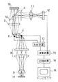
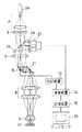
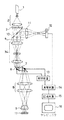
以下、図面を用いて実施例を説明する。先ず、第1実施例は、図1に示すように、光源手段としてのレーザ1と、ビームエキスパンダ2と、光束分割手段及び多重焦点生成手段としてのマイクロレンズアレー3と、多重光源生成手段と検出側微小開口とを兼ねる多孔板からなる共焦点板4と、第一のリレーレンズ5と、走査手段としての第一のガルバノミラー6及び第二のガルバノミラー7と、第二のリレーレンズ8と、対物レンズ9と、ハーフミラー10と、撮影レンズ11と、受光手段としてのイメージセンサ12と、標本像生成手段を構成する制御装置13,演算装置14,記憶装置15と、テレビモニタ16とから成っている。符号17は標本である。
【0052】
このような構成の本実施例においては、レーザ1から出射された光は、ビームエキスパンダ2で光束径が広げられ、マイクロレンズアレー3に、平行光線となって入射する。マイクロレンズアレー3は、同一特性の複数の微小なレンズが規則正しく配列された構造となっているため、入射した平行光は、各レンズごとに収束され、焦点位置において規則正しく配列される。そして、その焦点位置には、複数の微小開口を有する共焦点板4が配置されているので、そこで、規則正しく配列された複数の点光源と等価な多重点光源が生成されることになる。
【0053】
また、その場合における各点光源は、それらから発せられた光が、相互に干渉することなく、標本17上に集光されるようにするために、充分な間隔をもって配列されている。尚、その点については、E.M.McCabe,et.al.,“Direct-viewmicroscopy:optical sectioning strength for finite-sized, multiple- pinhole arrays", Jounal of Microscopy,Vol.184,Pt2,November 1996,pp.95-105 によれば、各点光源の間隔は標本面上におけるスポット径の10倍程度が適当である、と記載されている。
【0054】
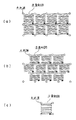
二つのガルバノミラー6,7は、近接して配置されており、夫々、制御装置13に接続され、同期して作動されるようになっている。そこで、共焦点板4上の各点光源から発した光が、第一のリレーレンズ5を介して第一のガルバノミラー6に集光されると、その第一のガルバノミラー6は、それらの光束を一方向(x軸方向)に走査し、第二のガルバノミラー7は、偏向された光束を更に直交する方向(y軸方向)へ走査する。その走査軌跡は、図2(a)に示すとおりであり、標本面上において隣接する四つの点光源によって囲まれた小領域内をカバーするようになっている。
【0055】
二つのガルバノミラー6,7によって偏向された光束は、第二のリレーレンズ8によって再び集光される。対物レンズ9は、その集光位置近傍に射出瞳を合わせるようにして配置されていて、その対物レンズ9を通った光束は、共焦点板4と共役位置に配置されている標本17面上で反射される。反射された光束は、それまでとは逆の光路を辿り、共焦点板4の微小開口を逆方向から透過することによって、共焦効果を得ることになる。光束の一部は、その後、マイクロレンズアレー3に戻ることなく、ハーフミラー10によって直角に偏向され、撮影レンズ11によって共焦点像がイメージセンサ12に投影され、撮像される。言うまでもなく、イメージセンサ12は、共焦点板4の微小開口に対応して規則正しく配列されている複数の受光素子の集合体であって、それらの受光素子が、共焦点板4の夫々の開口からの光束を独立して受光するようになっている。
【0056】
また、演算装置14には、イメージセンサ12から各受光素子の信号が入力され、また、制御装置13からは二つのガルバノミラー6,7の偏向量が入力されるようになっている。そこで、演算装置14は、予め記憶してある受光素子の位置座標と、ガルバノミラー6,7の偏向量とを用いて算出した記憶装置15内の番地に、各受光素子の信号に応じた値を、夫々、書き込んでいく。そして、一通り走査が終了したときには、記憶装置15に、標本17の視野全体の像が書き込まれたことになり、その標本像は、記憶装置15に接続されたテレビモニタ16に表示され、目視による観察が可能になっている。
【0057】
尚、上記した図2に(a)についての説明からも理解されるように、本実施例においては、マイクロレンズアレー3及び共焦点板4の微小開口の配列、即ち点光源の配列が、正方配列になっているが、規則的な配列であるならば、その他の配列となるようにしても差し支えなく、例えば、図2(b)のように、点光源が六角格子の配列をとるようにしても差し支えない。そのようにした場合においても、走査は、点光源によって分割された小領域内で偏向によって行われることになる。また、図2(a),図2(b)に示された走査軌跡は、いずれも一方向繰り返し走査であるが、図2(c)に示すように、折り返し走査を行うようにしてもよく、そのようにすることによって、全走査に要する時間を短くすることが可能になる。
【0058】
更に、本実施例においては、走査手段としてガルバノミラーを使用しているが、それ以外のもの、例えばポリゴンミラーや音響光学素子を使用しても構わない。また、本実施例を一部変形し、蛍光観察が行えるようにすることも可能である。その場合には、ハーフミラー10に代えてダイクロイックミラーを用い、そのダイクロイックミラーとイメージセンサ12の間に、レーザ1が発した光の波長を吸収し、使用する蛍光色素が発する蛍光だけを透過することのできる吸収フィルタを配置すればよいことになる。
【0059】
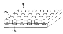
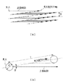
また、本実施例は、図3に示されているように変形させて実施することも可能である。この変形例は、ダイオードレーザマトリックス18が、単独で多重点光源生成手段を構成するようにしたものである。ダイオードレーザマトリックス18は、図4に示すように、行列状に配列された複数の活性領域18aの上に、共振器を含む基板18bを配置したものであり、複数の点光源を配列したものとみなすことができる。そして、このようにした場合には、共焦点板4は、図3に示すようにダイオードレーザマトリックス18と共役の位置に配置されることになる。尚、図3においては、図1に示したものと同じものに同じ符号を付けてあるので、その他の構成の説明は重複を避けるために省略する。
【0060】
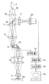
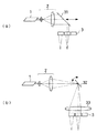
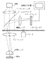
次に、図5を用いて第2実施例を説明する。尚、図5においては、図1に示したものと同じものに同じ符号を付けてある。本実施例の構成は、光源手段としてのレーザ1と、光線分割手段としての光ファイバ19と、共焦点板(スリット板)4と共に線状焦点生成手段を構成するシリンドリカルレンズアレー20と、第一のリレーレンズ5と、走査手段としてのガルバノミラー6と、ミラー21と、第二のリレーレンズ8と、対物レンズ9と、ハーフミラー10と、撮影レンズ11と、受光手段としてのラインセンサ22と、標本像生成手段を構成する制御装置13,演算装置14,記憶装置15と、テレビモニタ16と、標本17の位置を移動させるステージ駆動装置23とから成っている。
【0061】
レーザ1から出射された光束は、複数の光ファイバ19によって分割され、シリンドリカルレンズアレー20に入射する。夫々の光束は、シリンドリカルレンズアレー20の配列に対応して複数の線状焦点を結び、その線状焦点位置に共焦点板4が配置されている。この共焦点板4は、第1実施例の場合とは異なり、スリット状の複数の開口を有していて、レーザ1,光ファイバ19,シリンドリカルレンズアレー20と共に多重線光源生成手段を構成している。尚、この多重線光源生成手段を、周知のレーザアレーとシリンドリカルレンズアレー20とで構成するようにしても差し支えない。
【0062】
このようにして、共焦点板4を通過した各光束は、第一のリレーレンズ5を介してガルバノミラー6上に集光され、ガルバノミラー6は、線状化された光束を、その線の垂直方向に走査する。ガルバノミラー6によって偏向された光束は、ミラー21によって反射された後、第二のリレーレンズ8によって再び集光され、その集光位置に射出瞳を合わせて配置されている対物レンズ9を通って標本17の表面に達する。標本面で反射された光束は、それまでとは逆の光路を辿り、リレーレンズ5によって共焦点板4上に再び集光し、共焦効果をもたらす。共焦点板4のスリット開口を透過した光束の一部は、その後、シリンドリカルレンズアレー20には戻らず、ハーフミラー10によって偏向され、撮影レンズ11によって、ラインセンサ22上に集光され、標本像がラインセンサ22上に結像される。
【0063】
演算装置14には、制御装置13からガルバノミラー6の偏向量が入力され、ラインセンサ22からは撮像信号が入力されるようになっている。記憶装置16は、演算装置14に接続されていて、そこには、予め記憶しているラインセンサ22の各受光素子の位置座標と、ガルバノミラー6の偏向量とによって算出された番地が設定されている。従って、演算装置14は、ラインセンサ22の各受光素子から入力される撮像信号に対応した値を、各番地に書き込んでいく。そして、一通り走査が終了したときに、記憶装置15に、標本17の視野全体の像が書き込まれたことになり、その標本像は、記憶装置15に接続されたテレビモニタ16に表示される。
【0064】
本実施例においては、ステージ駆動装置23が、制御装置13と接続されていて、標本17を上下方向(光軸方向)へ移動させることが可能になっている。そのため、ガルバノミラー6による標本面の一回の走査が終わるたびに、標本17を少しずつ移動させ、複数の焦点位置における共焦点像を演算装置14に取り込むことにより、演算装置14は、それらの画像を基にして三次元像を構築し、それを、テレビモニタ16に表示できるようになっている。
【0065】
このように、本実施例は、線状の開口(スリット)を用いた共焦点装置として構成されていることから、第1実施例のように点状の開口を用いた共焦点装置に比較して、共焦点性は多少劣るが、一画面の走査が非常に短時間で終了するため、焦点位置の移動を行わせながらの三次元像の構築が高速に行えるという利点がある。また、本実施例においても、構成の一部を変えることによって、蛍光観察が行えるようにすることが可能である。その場合には、ハーフミラー10に代えてダイクロイックミラーを用い、そのダイクロイックミラーとラインセンサ22の間に、レーザ1が発した光の波長を吸収し、使用する蛍光色素が発する蛍光のみを透過する吸収フィルタを配置すればよいことになる。
【0066】
次に、図6及び図7を用いて、第3実施例を説明する。尚、図6においては、図1及び図5に示したものと同じものに同じ符号を付けてある。そこで、先ず、本実施例の構成は、光源手段としてのチタンサファイアレーザ24と、ビームエキスパンダ2と、光束分割手段及び多重焦点生成手段としてのマイクロレンズアレー3と、第一のリレーレンズ5と、走査手段としてのガルバノミラー6と、ミラー21と、第二のリレーレンズ8と、対物レンズ9と、ダイクロイックミラー25と、吸収フィルタ26と、受光手段としてのフォトンカウンタ27と、標本像生成手段を構成する制御装置13,演算装置14,記憶装置15と、テレビモニタ16とから成っている。
【0067】
チタンサファイアレーザ24から出射された光束は、ビームエキスパンダ2によって広げられ、マイクロレンズアレー3によって複数のビームに分割される。分割された夫々のビームは、マイクロレンズアレー3のレンズの配列に対応したパターンで、複数の点光源に準じる焦点を結ぶ。第一のリレーレンズ5は、マイクロレンズアレー3の焦点からの光をガルバノミラー6に集光し、ガルバノミラー6は、その光束を一方向、即ちx軸方向に走査する。ガルバノミラー6によって偏向された光束は、ミラー21によって反射され、第二のリレーレンズ8の方向へ偏向される。
【0068】
ところで、本実施例においては、マイクロレンズアレー3によって生成された焦点の配列は、図7(a)に示すように、ガルバノミラー6の走査方向に対して、微小な角度θををなす軸に沿って等間隔に配置されている。そして、ガルバノミラー6による走査は、上記したようにx軸方向の一次元のみで行われる。そして、図7(b)に拡大して示したように、各焦点の直径をdとし、焦点の間隔をlとすると、走査方向に対する焦点配列の軸の角度θが、tanθ≦d/lの関係を満たすようになっている。従って、ガルバノミラー6による一次元の走査だけでも、各焦点の軌跡が重なり合い、標本面上の全視野領域が照明ムラを生じないようになっている。
【0069】
このようにして走査され、ミラー21によって偏向された光束は、リレーレンズ8によって再び集光され、その集光位置に射出瞳を合わせて配置されている対物レンズ9を通り、マイクロレンズアレー3の焦点と共役位置に配置された標本17の表面に集光される。そして、その集光された照明光は、その焦点位置付近で2光子又は多光子励起による蛍光を誘導する。このようにして発した蛍光は、それまでの光路を逆に辿り、第一のリレーレンズ5を透過した後、ダイクロイックミラー25によって、マイクロレンズアレー3とは異なる方向へ偏向される。そして、光路の途中から反射して戻ってきた励起光が吸収フィルタ26によって除去された後、マイクロレンズアレー3の焦点と共役の位置に配置されているフォトンカウンタ27の受光面に集光する。
【0070】
演算装置14には、制御装置13からガルバノミラー6の偏向量が入力され、フォトンカウンタ27からは撮像信号が入力されるようになっている。記憶装置16は、演算装置14に接続されていて、そこには、予め記憶しているフォトンカウンタ27の受光面における複数の微小開口の位置座標と、ガルバノミラー6の偏向量とによって算出された番地が設定されている。従って、演算装置14は、フォトンカウンタ27から入力される像信号に対応した値を、各番地に書き込んでいく。そして、一通り走査が終了したときに、記憶装置15に、標本17の視野全体の像が書き込まれたことになり、その標本像は、記憶装置15に接続されたテレビモニタ16に表示される。
【0071】
このように、本実施例によれば、走査手段による走査を、上記したx軸方向のように一方向へのみ行えばよいことから、従来のシングルビーム走査装置を用いた共焦点顕微鏡に比較して、遙に高速に一画面の走査が終了する。また、本実施例の受光素子には、フォトンカウンタを用いているので、超高感度な2光子又は多光子の蛍光像を観察することが可能になる。
【0072】
尚、これまでに、三つの実施例を説明したが、各実施例の構成要素を相互に組み変えるようにしても、本発明の目的は達せられ、所定の効果を得ることが可能である。例えば、第3実施例における走査手段を第1実施例における走査手段として採用するようにしても何ら差し支えない。
【0073】
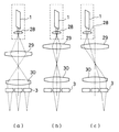
次に、図8を用いて、第4実施例を説明する。本実施例は、上記した第1実施例及び第3実施例のように、多重点光源生成手段にマイクロレンズアレー3を用いた場合、そのマイクロレンズアレー3の照明面積を調節できるようにした場合の実施例である。そのため、図8には、その説明に必要な構成要素だけを示してあり、また、これまでに示したものと同じものには同じ符号を付けてある。
【0074】
本実施例として示された構成は、光源手段としてのレーザ1と、三つのレンズ28,29,30と、マイクロレンズアレー3とから成っており、レンズ28はレーザ1と一体的に組み付けられている。レンズ29とレンズ30は光束径可変光学系を形成しており、レーザ1から出射した光束は、レンズ29とレンズ30の間隔を変えることによって、マイクロレンズアレー3に対する照明面積を調節できるようになっている。図8(a)は、そのような調節によって、マイクロレンズアレー3を広範囲に照明している場合を示し、図8(b)は、中心部分だけを照明している場合を示している。
【0075】
また、本実施例においては、レーザ1とレンズ28との一体構成部と、レンズ29,30やマイクロレンズアレー3を含むその他の光学系とが、相対的に、光軸に対して垂直方向へ移動可能になっていて、投影位置調節手段を形成している。そのため、図8(b)に示したように、レンズ29とレンズ30の間隔を大きくしておき、それらに対してレーザ1及びレンズ28を偏心させると、マイクロレンズアレー3の照明部位を調節でき、ひいては標本の照明部位を調節できることになる。図8(c)は、そのようにして調節した場合の一例を示している。
【0076】
このように、本実施例によれば、レンズ29とレンズ30の位置間隔を変えたり、それらとレンズ28を偏心させることにより、顕微鏡の視野範囲において、必要な部分のみを観察することが可能になるので、その他の部分にとらわれることなく、観察がし易いという利点があるほか、レーザ1からの出射光を、制限された領域に集中して照明させることが可能であるため、例えば暗い物体であっても、その部分を明るくして観察することができるという利点がある。
【0077】
尚、本実施例においては、レンズ29とレンズ30の位置間隔を変えたり、それらとレンズ28を偏心させたりして照明領域を調節しているが、本発明は、このような構成のみに限定されず、種々の構成が考えられる。例えば、予め複数の光学系を配置しておき、それらを切り換えて使用できるようにしても差し支えない。また、別の二つの変形例が、図9(a),図9(b)に示されている。これらの変形例は、いずれもビームエキスパンダ2とマイクロレンズアレー3の間に、ミラー31,32を配置したものである。そして、図9(a)に示した変形例は、ミラー31を図の左右方向へ移動させるようにしたものであり、図9(b)に示した変形例は、ミラー32の傾きを変えるようにしたものである。尚、図9(b)に示した変形例においては、ミラー32の傾きを変えても、マイクロレンズアレー3に光束が垂直に入射するようにするために、レンズ33が配置されている。
【0078】
次に、図10を用いて、第5実施例を説明する。尚、本実施例は、第1実施例における第一のリレーレンズ5の配置位置に、正,負,正の3枚のレンズからなるズームレンズ群34を配置しており、それによって、第1実施例の場合とは、二つのガルバノミラー6,7の機能が変わるようにしたものである。そのため、図1に示したものと同じものには同じ符号を付け、重複した構成の説明は省略する。
【0079】
本実施例においても、レーザ1から出射された光束は、ビームエキスパンダ2によって広げられた後、マイクロレンズアレー3によって複数の光束に分割され、夫々の焦点が共焦点板4の微小開口上に形成されることによって、規則正しく配列した点光源が生成されるようになっている。このようにして生成された複数の点光源は、倍率可変光学系即ちズームレンズ群34によって投影倍率を調整され、二つのガルバノミラー6,7、リレーレンズ8、対物レンズ9を経て、標本17上に投影される。また、その投影に際して、二つのガルバノミラー6,7は、制御装置13によって、走査の原点を調節できるようになっていて、標本17上における照明位置を調節できるようになっている。
【0080】
このように、本実施例によれば、ズームレンズ群34を調節することにより、標本17上における照明面積を変えることが可能となり、また、二つのガルバノミラー6,7の走査原点を調節することにより、標本17上における照明位置も変えることができるようになっている。そのため、標本視野上の必要な箇所のみを照明して、不要な照明を避けるようにすることが可能になる。更に、投影倍率を下げることにより、各点光源の、標本上での間隔が狭くなるため、一画面を生成するのに必要な走査時間を短縮することも可能になる。
【0081】
尚、本実施例においては、投影倍率に対応して、対物レンズ9の瞳位置における各点光源の光束径が変化するが、投影倍率が最大のときに、その光束径が対物レンズ9の瞳径を満たすようにしておけば、対物レンズ9の解像力を確保することが可能になる。
【0082】
以上説明したことからも明らかなように、各請求項に記載の構成のほか、以下に示す構成も本願発明の特徴である。
(1)前記標本像生成手段が、像形成手段と画像記憶装置とを含んでおり、前記画像記憶装置には、前記受光素子の夫々の受光面上での位置座標と前記走査手段の与える偏向量とから演算される標本の位置を表す番地が設定されていて、それらの番地に、前記像形成手段が、前記受光素子からの信号に対応した値を書き込むことにより標本像を形成するようにしたことを特徴とする請求項1に記載の走査型共焦点顕微鏡。
(2)前記複数の点光源又はそれに準じる焦点は、互いに所定の角度をなす二組の等間隔な平行線によって形成される交点上に配置され、前記走査手段が焦点によって分割される平行四辺形の小領域を走査するようにしたことを特徴とする請求項1又は上記(1)に記載の走査型共焦点顕微鏡。
(3)前記の所定の角度が直角であり、前記の小領域の形状が長方形又は正方形であることを特徴とする上記(2)に記載の走査型共焦点顕微鏡。
(4)前記複数の点光源又はそれに準じる焦点は、前記走査手段の走査方向に対して微小な角度をなす等間隔な平行線上に等間隔に配置されており、また、前記走査手段は、一方向のみに走査を行う走査手段であることを特徴とする請求項1又は上記(1)に記載の走査型共焦点顕微鏡。
(5)前記した微小な角度は、前記走査手段によって前記複数の点光源又はそれに準じる焦点が走査されたとき、隣接する走査軌跡が接するか又は一部が重なり合うように定められていることを特徴とする上記(4)に記載の走査型共焦点顕微鏡。
(6)前記受光素子がイメージセンサであることを特徴とする請求項1、又は上記(1)〜(5)の何れかに記載の走査型共焦点顕微鏡。
(7)前記受光素子は、前記検出側微小開口と相似形に配列されたフォトマルチプライアであることを特徴とする請求項1、又は上記(1)〜(5)の何れかに記載の走査型共焦点顕微鏡。
(8)前記受光素子は、前記検出側微小開口と相似形に配列されたフォトンカウンタであることを特徴とする請求項1、又は上記(1)〜(5)の何れかに記載の走査型共焦点顕微鏡。
(9)前記走査手段が、ガルバノミラーであることを特徴とする請求項1、又は上記(1)〜(8)の何れかに記載の走査型共焦点顕微鏡。
(10)前記走査手段が、ポリゴンミラーであることを特徴とする請求項1、又は上記(1)〜(8)の何れかに記載の走査型共焦点顕微鏡。
(11)前記走査手段が、音響光学素子であることを特徴とする請求項1、又は上記(1)〜(8)の何れかに記載の走査型共焦点顕微鏡。
(12)前記多重点光源生成手段が、一つ若しくは複数の点光源又はそれに準じる光を生成する光源手段と、前記光源手段からの光束を複数の光束に分割する光束分割手段と、前記光束分割手段により分割された複数の光束から複数の焦点を生成する多重焦点生成手段とから成っていることを特徴とする請求項1、又は上記(1)〜(11)の何れかに記載の走査型共焦点顕微鏡。
(13)前記光束分割手段と前記多重焦点生成手段は、マイクロレンズアレーで兼ねていることを特徴とする上記(12)に記載の走査型共焦点顕微鏡。
(14)前記光束分割手段が、マイクロレンズアレーであり、前記多重焦点生成手段が、前記マイクロレンズアレーの焦点位置に複数の小開口を有する多孔板であることを特徴とする上記(12)に記載の走査型共焦点顕微鏡。
(15)前記多孔板の小開口は、前記検出側微小開口も兼ねていることを特徴とする上記(14)に記載の走査型共焦点顕微鏡。
(16)前記光束分割手段と前記多重焦点生成手段は、複数の光ファイバで兼ねていることを特徴とする上記(12)に記載の走査型共焦点顕微鏡。
(17)前記光源手段が、レーザ光源であることを特徴とする上記(12)に記載の走査型共焦点顕微鏡。
(18)前記多重点光源生成手段が、ダイオードレーザマトリクスであることを特徴とする請求項1、又は上記(1)〜(11)の何れかに記載の走査型共焦点顕微鏡。
(19)前記標本像生成手段が、像形成手段と画像記憶装置とを含んでおり、前記画像記憶装置には、前記受光素子の夫々の受光面上での位置座標と前記走査手段の与える偏向量とから演算される標本の位置を表す番地が設定されていて、それらの番地に、前記像形成手段が、前記受光素子からの信号に対応した値を書き込むことにより標本像を形成するようにしたことを特徴とする請求項2に記載の走査型共焦点顕微鏡。
(20)前記複数の線光源又はそれに準じる線状焦点は、互いに平行で等間隔に配列され、また、前記走査手段は前記複数の線光源又はそれに準じる線状焦点と所定の角度をなす方向に一方向のみに走査を行う走査手段であることを特徴とする請求項2又は上記(19)に記載の走査型共焦点顕微鏡。
(21)前記走査手段は、前記複数の線光源又はそれに準じる線状焦点は、その線と直角をなす方向に一方向のみに走査を行う走査手段であることを特徴とする上記(20)に記載の走査型共焦点顕微鏡。
(22)前記受光素子は、前記検出側線状開口と相似形に配列されたラインセンサであることを特徴とする請求項2、又は上記(19)〜(21)の何れかに記載の走査型共焦点顕微鏡。
(23)前記走査手段が、ガルバノミラーであることを特徴とする請求項2、又は上記(19)〜(22)の何れかに記載の走査型共焦点顕微鏡。
(24)前記走査手段が、ポリゴンミラーであることを特徴とする請求項2、又は上記(19)〜(22)の何れかに記載の走査型共焦点顕微鏡。
(25)前記走査手段が、音響光学素子であることを特徴とする請求項2、又は上記(19)〜(22)の何れかに記載の走査型共焦点顕微鏡。
(26)前記多重線光源生成手段が、一つ若しくは複数の点光源又はそれに準じる光を生成する光源手段と、前記光源手段からの光束を複数の光束に分割する光束分割手段と、前記光束分割手段により分割された複数の光束から複数の線状焦点を生成する線状焦点生成手段とから成っていることを特徴とする請求項2、又は上記(19)〜(25)の何れかに記載の走査型共焦点顕微鏡。
(27)前記線状焦点生成手段は、シリンドリカルレンズアレーを含んでいることを特徴とする上記(26)に記載の走査型共焦点顕微鏡。
(28)前記線状焦点生成手段は、前記シリンドリカルレンズアレーと、該シリンドリカルレンズアレーの焦点位置に複数の線状開口を有するスリット板とから成ることを特徴とする上記(27)に記載の走査型共焦点顕微鏡。
(29)前記スリット板は、前記検出側線状開口も兼ねていることを特徴とする上記(28)に記載の走査型共焦点顕微鏡。
(30)前記光源手段が、レーザ光源であることを特徴とする上記(26)に記載の走査型共焦点顕微鏡。
(31)前記光束分割手段が、複数の光ファイバでであることを特徴とする上記(26)〜(30)の何れかに記載の走査型共焦点顕微鏡。
(32)前記光束分割手段が、シリンドリカルレンズアレーであることを特徴とする上記(26)〜(30)の何れかに記載の走査型共焦点顕微鏡。
(33)前記光源手段と前記光束分割手段を、レーザーアレーが兼ねていることを特徴とする上記(26)〜(29)の何れかに記載の走査型共焦点顕微鏡。
(34)前記標本像生成手段が、像形成手段と画像記憶装置とを含んでおり、前記画像記憶装置には、前記受光素子の夫々の受光面上での位置座標と前記走査手段の与える偏向量とから演算される標本の位置を表す番地が設定されていて、それらの番地に、前記像形成手段が、前記受光素子からの信号に対応した値を書き込むことにより標本像を形成するようにしたことを特徴とする請求項3に記載の走査型蛍光顕微鏡。
(35)前記複数の焦点は、互いに所定の角度をなす二組の等間隔な平行線によって形成される交点上に配置され、前記走査手段が焦点によって分割される平行四辺形の小領域を走査するようにしたことを特徴とする請求項3又は上記(34)に記載の走査型蛍光顕微鏡。
(36)前記の所定の角度が直角であり、前記の小領域の形状が長方形又は正方形であることを特徴とする上記(35)に記載の走査型蛍光顕微鏡。
(37)前記複数の焦点は、前記走査手段の走査方向に対して微小な角度をなす等間隔な平行線上に等間隔に配置されており、また、前記走査手段は、一方向のみに走査を行う走査手段であることを特徴とする請求項3又は上記(34)に記載の走査型蛍光顕微鏡。
(38)前記した微小な角度は、前記走査手段によって前記複数の焦点が走査されたとき、隣接する走査軌跡が接するか又は一部が重なり合うように定められていることを特徴とする上記(37)に記載の走査型蛍光顕微鏡。
(39)前記受光素子は、前記焦点と略共役な位置に配列されたフォトンカウンタであることを特徴とする請求項3、又は上記(34)〜(36)の何れかに記載の走査型蛍光顕微鏡。
(40)前記走査手段が、ガルバノミラーであることを特徴とする請求項3、又は上記(34)〜(39)の何れかに記載の走査型蛍光顕微鏡。
(41)前記走査手段が、ポリゴンミラーであることを特徴とする請求項3、又は上記(34)〜(39)の何れかに記載の走査型蛍光顕微鏡。
(42)前記走査手段が、音響光学素子であることを特徴とする請求項3、又は上記(34)〜(39)の何れかに記載の走査型蛍光顕微鏡。
(43)前記光束分割手段と前記多重焦点生成手段を、マイクロレンズアレーで兼ねていることを特徴とする請求項3、又は上記(34)〜(42)の何れかに記載の走査型蛍光顕微鏡。
(44)前記光束分割手段と前記多重焦点生成手段を、複数の光ファイバが兼ねていることを特徴とする請求項3、又は上記(34)〜(42)の何れかに記載の走査型蛍光顕微鏡。
(45)前記標本像生成手段が、像形成手段と画像記憶装置とを含んでおり、前記画像記憶装置には、前記受光素子の夫々の受光面上での位置座標と前記走査手段の与える偏向量とから演算される標本の位置を表す番地が設定されていて、それらの番地に、前記像形成手段が、前記受光素子からの信号に対応した値を書き込むことにより標本像を形成するようにしたことを特徴とする請求項4に記載の走査型蛍光顕微鏡。
(46)前記複数の線状焦点は、互いに平行で等間隔に配列されており、また、前記走査手段は前記複数の線状焦点と所定の角度をなす方向に一方向のみに走査を行う走査手段であることを特徴とする請求項4又は上記(45)に記載の走査型蛍光顕微鏡。
(47)前記走査手段は、前記複数の線状焦点の線と直角をなす方向に一方向のみに走査を行う走査手段であることを特徴とする上記(46)に記載の走査型蛍光顕微鏡。
(48)前記受光素子は、前記複数の線状焦点と略共役な位置に配列されたラインセンサであることを特徴とする請求項4、又は上記(45)〜(47)の何れかに記載の走査型蛍光顕微鏡。
(49)前記走査手段が、ガルバノミラーであることを特徴とする請求項4、又は上記(45)〜(48)の何れかに記載の走査型蛍光顕微鏡。
(50)前記走査手段が、ポリゴンミラーであることを特徴とする請求項4、又は上記(45)〜(48)の何れかに記載の走査型蛍光顕微鏡。
(51)前記走査手段が、音響光学素子であることを特徴とする請求項4、又は上記(45)〜(48)の何れかに記載の走査型蛍光顕微鏡。
(52)前記光束分割手段が、複数の光ファイバであることを特徴とする請求項4、又は上記(45)〜(51)の何れかに記載の走査型蛍光顕微鏡。
(53)前記多重線状焦点生成手段が、シリンドリカルレンズアレーであることを特徴とする請求項4、又は上記(45)〜(52)の何れかに記載の走査型蛍光顕微鏡。
(54)前記光束分割手段と前記多重線状焦点生成手段を、シリンドリカルレンズアレーが兼ねていることを特徴とする請求項4、又は上記(45)〜(51)の何れかに記載の走査型蛍光顕微鏡。
(55)前記光束分割手段が、シリンドリカルレンズアレーであり、また、前記多重線状焦点生成手段が、前記シリンドリカルレンズアレーの焦点位置に複数の線状開口を有するスリット板であることを特徴とする請求項4、又は上記(45)〜(51)の何れかに記載の走査型蛍光顕微鏡。
(56)光束分割数調節手段が備えられて、前記光束分割手段によって分割される光束の数を調節できるようにしたことを特徴とする請求項3若しくは4、又は上記(12)〜(17)、(26)〜(32)、(34)〜(55)の何れかに記載の走査型顕微鏡。
(57)前記光束分割数調節手段が、前記光源手段と前記光束分割手段との間に配置された光束径可変光学系であることを特徴とする上記(56)に記載の走査型顕微鏡。
(58)投影倍率調節手段が、前記多重点光源生成手段と標本との間に配置されており、標本上に対する前記複数の点光源又はそれに準じる焦点の投影倍率を調節できるようにしたことを特徴とする請求項1若しくは3、又は上記(1)〜(18)、(34)〜(44)、(56)、(57)の何れかに記載の走査型顕微鏡。
(59)投影倍率調節手段が、前記多重線光源生成手段と標本との間に配置されており、標本上に対する前記複数の線光源又はそれに準じる線状焦点の投影倍率を調節できるようにしたことを特徴とする請求項2若しくは4、又は上記(19)〜(33)、(45)〜(57)の何れかに記載の走査型顕微鏡。
(60)投影位置調節手段が備えられていて、前記複数の点光源又はそれに準じる焦点の標本上への投影位置を調節できるようにしたことを特徴とする請求項1若しくは3、又は上記(1)〜(18)、(34)〜(44)、(56)〜(59)の何れかに記載の走査型顕微鏡。
(61)投影位置調節手段が備えられていて、前記複数の線光源又はそれに準じる線状焦点の標本上への投影位置を調節できるようにしたことを特徴とする請求項2若しくは4、又は上記(19)〜(33)、(45)〜(59)の何れかに記載の走査型顕微鏡。
(62)前記投影位置調節手段が、前記多重点光源生成手段と標本との間に配置された光束偏向手段であることを特徴とする上記(60)又は(61)に記載の走査型顕微鏡。
(63)前記投影位置調節手段を、前記走査手段が兼ねていることを特徴とする上記(60)又は(61)に記載の走査型顕微鏡。
(64)投影位置調節手段が、前記光源手段と前記光束分割手段の間に配置されており、前記光源手段を発した光束が前記光束分割手段に入射する位置を調節できるようにしたことを特徴とする請求項3若しくは4、又は上記(12)〜(17)、(26)〜(32)、(34)〜(55)の何れかに記載の走査型顕微鏡。
【0083】
【発明の効果】
上記のように、本発明の走査型顕微鏡によれば、照明効率が良く且つリアルタイムで観察でき、また、高感度な受光素子を使用することができるために、例えば蛍光観察のように、非常に暗い標本像の観察も可能となり、更に、共焦点顕微鏡の有する高解像性を損なわず且つ広い視野を有したままで受光素子の総数を少なくし、消費電力を少なくすることが可能となる。また、必要に応じて、標本視野内の所望の領域のみを効率よく観察できるようにすることも可能である。
【図面の簡単な説明】
【図1】第1実施例の構成図である。
【図2】第1実施例に採用することの可能な走査軌跡を示す図であって、図2(a),図2(b)は、夫々、点光源が正方配列と六方格子配列されているときの一方向繰り返し走査の場合を示し、図2(c)は、点光源が正方配列されているときの折り返し走査の場合を示している。
【図3】第1実施例の変形例を示す構成図である。
【図4】図3におけるダイオードレーザマトリックスの構造を示した説明図である。
【図5】第2実施例の構成図である。
【図6】第3実施例の構成図である。
【図7】図7(a)は第3実施例における焦点の配列と走査軌跡との関係を示す図であって、図7(b)は図7(a)の部分拡大図である。
【図8】第4実施例の構成図であって、マイクロレンズアレーの照明領域の調節状態を示すものであり、図8(a)は広範囲の照明状態、図8(b)は中心部分の照明状態、図8(c)は軸外部分の照明状態を示している。
【図9】第4実施例の変形例を示す構成図であって、図9(a)はミラーを直線的に移動させるようにした場合を示し、図8(b)はミラーの傾きを変えるようにした場合を示している。
【図10】第5実施例の構成図である。
【図11】従来例の基本構成図である。
【図12】他の従来例の基本構成図である。
【符号の説明】
1 レーザ
2 ビームエキスパンダ
3 マイクロレンズアレー
4 共焦点板
5,8 リレーレンズ
6,7 ガルバノミラー
9 対物レンズ
10 ハーフミラー
11 撮像レンズ
12 イメージセンサ
13 制御装置
14 演算装置
15 記憶装置
16 テレビモニタ
17 標本
18 ダイオードレーザマトリックス
18a 活性領域
18b 基板
19 光ファイバ
20 シリンドリカルレンズアレー
21,31,32 ミラー
22 ラインセンサ
23 ステージ駆動装置
24 チタンサファイアレーザ
25 ダイクロイックミラー
26 吸収フィルタ
27 フォトンカウンタ
28,29,30,33 レンズ
34 ズームレンズ群[0001]
BACKGROUND OF THE INVENTION
The present invention relates to a scanning microscope of a type that performs confocal scanning.
[0002]
[Prior art]
This type of microscope has been proposed and commercialized in many types, as shown in TRCorle and GSKino, “Confocal Scanning Optical Microscopy and Related Imaging Systems”, Academic Press (1966). However, the types of confocal scanning devices used in them can be broadly classified into two types: those using a single beam scanning device and those using a multi-beam scanning device. Therefore, the basic configuration of these two types of microscopes will be described below.
[0003]
First, a basic configuration of a confocal microscope (hereinafter referred to as a single beam scanning microscope) using a single beam scanning apparatus will be described with reference to FIG. The light beam emitted from the light source is condensed at one point by the condensing lens, and the transmission image of the first minute aperture arranged there is formed on the sample via the first relay lens and the objective lens. . The light beam reflected by the sample is deflected in a direction different from the direction of the first minute aperture by a beam splitter disposed between the objective lens and the first relay lens. The deflected light beam is condensed by the second relay lens on the second minute aperture at the conjugate position of the first minute aperture, and the intensity of the transmitted light is detected by a detector such as a photomultiplier. It has come to be.
[0004]
A scanning device is disposed between the objective lens and the beam splitter. This scanning device has, for example, a galvanometer mirror or a polygon mirror, and scans the image of the first minute aperture on the sample surface. The controller connected to the scanning device and the detector detects the imaging position of the first minute aperture on the sample from the deflection amount of the light beam by the scanning device, and the detection signal and the imaging position at the imaging position are detected. A sample image in a wide area is obtained by the output signal from the detector, and is displayed on an image output device such as a television monitor. When a single mode oscillation laser is used as the light source, the arrangement of the first minute aperture is often omitted.
[0005]
Next, a basic configuration of a confocal microscope in the case where a Nipo disk is used as an example of a multi-beam scanning device as disclosed in JP-T-1-503493 will be described with reference to FIG. The luminous flux emitted from the light source is irradiated onto the Nipo disk by the condenser lens. A plurality of light beams divided by transmitting through a plurality of small apertures provided in the Nipo disk are condensed on one point on the sample via a relay lens and an objective lens, respectively. The light beam reflected from the sample is condensed again on the small opening of the Nipo disk through the objective lens and the relay lens.
[0006]
The beam splitter disposed between the Nipo disk and the condenser lens deflects the transmitted light from the Nipo disk in a direction different from that of the light source, and the photographing lens condenses it on the image sensor. Therefore, an image proportional to the reflectance of the sample is obtained on the image sensor and displayed on the image output device. Since the plurality of small openings provided in the Nipo disk are provided at a predetermined interval, the illumination that hits the sample at once is multi-spot illumination. However, since the Nipo disk is rotated at high speed by the motor, all the specimen surfaces can be scanned in a short time, and confocal observation can be performed with the naked eye.
[0007]
In this way, as can be seen from the difference between the basic configurations of the two, the single beam scanning microscope takes time to scan the entire field of view of the microscope instead of having good illumination efficiency of the light source. Real-time observation is impossible. In that respect, confocal microscopes using multi-beam scanning devices (hereinafter referred to as multi-beam scanning microscopes), including those using Nipo discs as described above, have a very short scanning time. Real-time observation is possible, and it is very convenient. The present invention relates to a confocal microscope using such a multi-beam scanning device. As a conventional example thereof, JP-A-5-60980 and JP-A-5-60980 are disclosed. There are some which are described in Kaihei 8-21296.
[0008]
[Problems to be solved by the invention]
Incidentally, the multi-beam scanning microscope suitable for such real-time observation also has various problems. As one of those problems, there is a problem of illumination efficiency. That is, when a Nipo disk is used as a scanning device as described above, most of the light emitted from the light source is blocked by the surface of the Nipo disk that is not provided with a small opening. The efficiency is remarkably deteriorated, and the fluorescence observation or the like cannot be performed substantially as it is. Thus, several methods for improving this point have been proposed. One method is disclosed in the above-mentioned Japanese Patent Application Laid-Open No. 5-60980.
[0009]
According to the method, a laser is used as a light source, and a condensing means such as a microlens array is provided between the condenser lens and the beam splitter, so that the light from the laser is divided and The light is collected at the opening position, and the light collecting means is rotated integrally with the Nipo disk by a motor. However, with this method, the illumination efficiency is dramatically improved and fluorescence observation is possible. However, on the other hand, it is very troublesome to manufacture the light collecting means and the Nipo disk in one piece. There is.
[0010]
In addition, in the conventional multi-beam scanning microscope including the case where a Nipo disk is used, the position of the specimen and the position of the light receiving element correspond to each other, so that the resolution determined by the optical system of the microscope is improved. In order to capture the sample image while being held, a highly integrated image sensor such as a CCD is often used as the light receiving means. However, the higher the integration of the image sensor, the smaller the light receiving area per unit pixel and the lower the sensitivity. Therefore, the multi-beam scanning microscope cannot detect with higher sensitivity than the single beam scanning microscope. There is a problem. Furthermore, since the power consumption of the image sensor is proportional to the number of light receiving elements, there is a problem that the power consumption is higher for a highly integrated image sensor. Therefore, it is conceivable to use a high-sensitivity imaging tube with low power consumption instead of the image sensor, but in that case, there is a problem that the resolution is inferior to that of the image sensor.
[0011]
Further, a number of multi-beam scanning microscopes that do not use a Nipo disk have been proposed. However, in the above-mentioned Japanese Patent Application Laid-Open No. 8-21296, light source means composed of a matrix of a plurality of point light sources, each light source, There is disclosed a technique in which a specimen is scanned by periodically blinking each point light source by using a detecting means arranged at a conjugate position, thereby eliminating a mechanically movable part. However, even in the case of this conventional example, most of the light emitted from the light source is shielded, and only the scanning spot portion is used as illumination light, so that the illumination efficiency is extremely low. Also, as the light receiving means, a highly integrated image sensor must be used, and the light receiving sensitivity cannot be increased. In addition, there is a problem that alignment of each highly integrated point light source and detector is also difficult.
[0012]
The present invention has been made to solve such problems, and an object thereof is to provide a scanning microscope capable of real-time observation with high illumination efficiency. Another object of the present invention is to provide a scanning microscope capable of using a highly sensitive light receiving element and capable of observing a very dark specimen image such as a fluorescent image. Still another object of the present invention is to provide an inexpensive scanning microscope that reduces the total number of light-receiving elements and reduces power consumption while maintaining the wide field of view without impairing the high resolution of the confocal microscope. It is to be.
[0013]
[Means for Solving the Problems]
In order to achieve the above object, the scanning microscope of the present invention is divided into a plurality of point light sources that are regularly arranged or a multi-point light source generating unit that generates a focal point equivalent thereto, and a plurality of the point light sources or focal points equivalent thereto. In a small area By deflection Scanning means for performing scanning, a plurality of detection-side minute apertures arranged at positions conjugate to the plurality of point light sources or the focal points equivalent thereto, and a plurality of light receiving the light transmitted through the plurality of detection-side minute apertures independently And a specimen image generating means for forming a specimen image from a deflection amount given by the scanning means and a signal received by the light receiving means.
In order to achieve the above object, the scanning microscope of the present invention comprises a plurality of line light sources arranged regularly or a multi-line light source generating means for generating a linear focal point equivalent thereto, and the adjacent line light sources or the adjacent line light sources. In a small area sandwiched by conforming linear focal points By deflection The scanning means for performing scanning, and the plurality of line light sources or the linear focus equivalent thereto are arranged at conjugate positions. plural A detection-side linear opening; plural A light receiving means comprising a plurality of light receiving elements arranged at a position conjugate with the detection-side linear opening; a sample image generating means for forming a sample image from the deflection amount given by the scanning means and a signal received by the light receiving means; To be equipped with.
Furthermore, in order to achieve the above object, a scanning microscope according to the present invention includes a light source unit composed of an ultrashort pulse laser, a beam splitting unit for splitting a beam from the light source unit into a plurality of beams, and the beam splitting. A multi-focus generating means for generating a plurality of focal points regularly arranged from a plurality of light beams divided by the means, and a small area divided by the plurality of the focal points. By deflection Fluorescence image of the sample from the scanning means for scanning, the light receiving means comprising a plurality of light receiving elements arranged at substantially conjugate positions of the plurality of focal points, the deflection amount given by the scanning means and the signal received by the light receiving means And a sample image generating means for forming the.
In order to achieve the above object, a scanning microscope according to the present invention comprises a light source means comprising an ultrashort pulse laser, a light beam splitting means for splitting a light beam from the light source means into a plurality of light beams, and the light beam. A multiple linear focal point generating unit that generates a plurality of linear focal points regularly arranged from a plurality of light beams divided by the dividing unit, and a small region sandwiched by the adjacent linear focal points; By deflection A scanning unit that performs scanning, a light receiving unit that includes a plurality of light receiving elements disposed at substantially conjugate positions of the plurality of linear focal points, a deflection amount given by the scanning unit, and a signal received by the light receiving unit A sample image generating means for forming a fluorescent image is provided.
[0014]
DETAILED DESCRIPTION OF THE INVENTION
As for the embodiments of the invention of the present application, first, embodiments of the invention related to the scanning microscope capable of achieving the above-mentioned object and the respective operational effects will be described, and then added to the four inventions. The four preferred configurations that can be applied and their operational effects will be described, and then each embodiment will be described with reference to FIGS.
[0015]
First, the invention described in claim 1 will be described. The microscope of the present invention includes a plurality of point light sources arranged regularly or a multi-point light source generating means for generating a focal point equivalent thereto, and a small area divided by the point light source or the focal point. By deflection Light receiving means comprising a scanning means for scanning, a plurality of detection-side minute apertures arranged at positions conjugate with the point light source or the focal point, and a plurality of light-receiving elements that individually receive light transmitted through the detection-side minute openings. And a sample image generating means for forming a sample image from the deflection amount given by the scanning means and the signal received by the light receiving means.
[0016]
According to the microscope of the present invention, since a plurality of point light sources generated by the multi-point light source generation unit or a focal point equivalent thereto are projected onto the specimen, the light source light has a low shielding rate and efficient illumination. It becomes possible. Further, as is well known, the scanning time for illuminating the entire field of view of the specimen is proportional to the area of the area to be scanned, but according to the present invention, a plurality of point light sources projected on the specimen or equivalent thereto. In the range of a small area divided by the focus By deflection Since scanning only needs to be performed, an image can be generated at a higher speed than a conventional single beam scanning microscope, and a specimen image can be observed in real time.
[0017]
Further, unlike a microscope using a Nipo disk as described above, the light receiving elements may be arranged in a one-to-one relationship with respect to each point light source or each corresponding focal point, so the total number of light receiving elements is extremely small. In addition, it is possible to widen the interval between them. Therefore, a photomultiplier having a high sensitivity and a large element can be adopted as the light receiving means, and a highly sensitive fluorescent image can be detected. Further, since the total number of light receiving elements can be made the same as the number of point light sources or focal points corresponding thereto, and the distance between the light receiving elements can be widened, the alignment between the point light sources or focal points corresponding thereto and the light receiving elements is facilitated.
[0018]
Further, the sample image generating means in the present invention includes an image forming means and an image storage device, and the image storage device is given in advance the position coordinates on the respective light receiving surfaces of each light receiving element and the scanning means. Addresses representing the position of the sample calculated from the deflection amount are set, and the image forming means writes a value corresponding to the signal from the light receiving element to these addresses to form a sample image. In this case, when one scan is completed, an image of the entire field of view of the sample is formed in the storage device, and if it is displayed on the image display device, the sample image can be observed. It becomes possible.
[0019]
Furthermore, in the present invention, the point light source or the focal point is arranged on an intersection formed by two sets of equally spaced parallel lines that form a predetermined angle with each other. In In addition, the scanning means scans a small area of the parallelogram divided by the focal point. By deflection It is convenient to scan. In particular, if the shape of the small area is rectangular or square, the scanning means can be easily manufactured. It is also preferable that the point light sources or the focal points are arranged at equal intervals on parallel lines that are equally spaced and have a minute angle with respect to the scanning direction of the scanning means. That is, in such a case, the scanning means need only be scanned in one direction, and the configuration of the scanning means can be further simplified as compared with the case of scanning a two-dimensional region. become. Furthermore, in this case, if the scanning trajectories of adjacent regions are in contact with each other or partially overlap, it is possible to form a whole sample image without illumination unevenness by scanning in one direction.
[0020]
As the multiple point light source generating means in the present invention, a diode laser matrix can be used. The diode laser matrix is a collection of semiconductor lasers arranged in a plane, and can be regarded as a collection of regularly arranged point light sources.
Moreover, it is preferable to use a galvanometer mirror, a polygon mirror, or an acoustooptic device as the scanning means in the present invention. In any case, it is possible to perform high-speed and stable scanning with a simple configuration.
[0021]
As the light receiving means in the present invention, it is preferable to use an image sensor, a photomultiplier, a photon counter, or the like. When the image sensor is used, since the light receiving elements are regularly arranged, it is easy to arrange the light receiving elements at conjugate positions with the respective point light sources. In addition, when a photomultiplier arranged in a similar shape to the detection-side micro-aperture described above is used, it becomes possible to detect a sample image with higher sensitivity than when a normal image sensor is used, and the fluorescence image can be detected. Detection is also possible. Furthermore, when using a photon counter arranged in a similar manner to the detection side micro-aperture described above, it is possible to detect a sample image with higher sensitivity than when using a photomultiplier, and a weak fluorescent image. It is also possible to detect this.
[0022]
Further, the multi-point light source generating means in the present invention includes one or a plurality of point light sources, or a light source means for generating light equivalent thereto, a light beam dividing means for dividing a light beam from the light source means into a plurality of light beams, and A plurality of focal points that conform to a plurality of point light sources can be generated even when configured with a multi-focus generation unit that generates a plurality of focal points from the light beams divided by the light beam dividing unit.
[0023]
In that case, if a laser light source is used as the light source means, a high-luminance point light source can be obtained. Further, the light beam splitting means and the multiple focus generating means can be used as a plurality of optical fibers. If light source light is incident on the incident end of the optical fiber, the exit end can be used as a point light source. Furthermore, if the light beam splitting means and the multifocal point generating means are shared by a microlens array, the configuration becomes simple. However, there are cases where a focal point according to a point light source cannot be generated only with a microlens array. Therefore, in that case, the microlens array is used only as the beam splitting means, the perforated plate is used as the multifocal generation means, and a plurality of small openings formed in the microlens array are arranged at the focal position of the microlens array. You can do that. In addition, in such a case, if the small apertures also serve as the detection-side minute apertures described above depending on the configuration of the optical system, the configuration is simplified, and the small apertures of the perforated plate and the detection-side minute apertures are simplified. It becomes possible to make positioning with the opening unnecessary.
[0024]
Next, the invention described in
[0025]
The microscope of the present invention includes a plurality of regularly arranged line light sources or multi-line light source generating means for generating a linear focus equivalent thereto, and a small region sandwiched between the line light sources or the linear focus. By deflection Light reception comprising scanning means for scanning, a plurality of detection-side linear openings arranged at positions conjugate with the line light source or the linear focus, and a plurality of light-receiving elements arranged at positions conjugate with the detection-side linear openings. And a specimen image generating means for forming a specimen image from the amount of deflection given by the scanning means and a signal received by the light receiving means. Is ing
[0026]
According to the present invention, since a plurality of line light sources generated by the multi-line light source generation unit or a linear focus equivalent thereto are projected onto the specimen, the light source light has a low shielding rate and efficient illumination is possible. become. Further, the scanning for illuminating the entire field of view of the specimen can be performed only on the line segment connecting adjacent linear light sources or linear focal points projected onto the specimen. Compared to the case of the present invention, it is suitable for shortening the time required for the entire scanning and for achieving ultra-high speed.
[0027]
In the case of the present invention, the confocal effect can be obtained only in the direction perpendicular to the longitudinal direction of the linear light source or the linear focal point, but it is possible to construct a three-dimensional image by the optical sectioning effect. By combining the scanning in the axial direction, a high-speed 3D image can be captured. Furthermore, since the light receiving elements only need to be arranged at a position conjugate with each line light source or each linear focal point, the total number of light receiving elements can be reduced as compared with a confocal microscope using a conventional image sensor as a light receiving means. Each of the intervals can be widened, so that the alignment between the linear light source or the linear focus and the light receiving element is facilitated.
[0028]
Also in the present invention, the sample image generating means includes the image forming means and the image storage device, and the image forming means has a value corresponding to the signal from the light receiving element at a predetermined address provided in the image storage device. Is written and a sample image is formed, the image of the entire field of view of the sample is formed in the storage device at the time when one scan is completed. The specimen image can be observed.
[0029]
In the present invention, the linear light sources or the linear focal points are arranged in parallel with each other at equal intervals, and the scanning means is unidirectional in a direction that forms a predetermined angle with respect to the longitudinal direction of the linear light sources or the linear focal points. If only scanning is performed, a sample image of the entire field of view can be formed in a short scanning time. In particular, if only one direction is scanned in a direction perpendicular to the longitudinal direction of the linear light source or the linear focal point, the entire specimen image can be formed in the shortest time.
[0030]
Also in the present invention, it is preferable to use a galvanometer mirror, a polygon mirror, or an acoustooptic device as the scanning means, and it is possible to perform high-speed and stable scanning with a simple configuration. Further, as the light receiving means in the present invention, if a line sensor arranged in a similar shape to the detection-side linear openings is used, the alignment of the light receiving elements is simplified.
[0031]
Further, the multi-line light source generating means in the present invention is a light source means for generating one or a plurality of point light sources or light equivalent thereto, a light beam splitting means for splitting a light beam from the light source means into a plurality of light beams, and the light beam. If it is configured with linear focus generating means for generating a plurality of linear focal points from the light beam divided by the splitting means, it becomes possible to efficiently obtain a high-brightness linear focus.
[0032]
In that case, when a laser light source is used as the light source means, a high-luminance point light source can be obtained. In addition, a plurality of optical fibers may be used as the light beam dividing means. If light source light is incident on the incident end of the optical fiber, the light beam can be split at the exit end. Furthermore, if a laser array is used to serve as both the light source means and the light beam splitting means, the configuration becomes simple.
[0033]
If a cylindrical lens array is used as the linear focal point generating means in the present invention, a plurality of linear focal points can be generated from parallel light beams emitted from the light source means. In addition, when a linear focus similar to a linear light source cannot be obtained with only a cylindrical lens array, a slit plate having a plurality of linear openings is used in addition to the cylindrical lens array, and the linear openings are formed. What is necessary is just to make it arrange | position to each focus position of a cylindrical lens array. Furthermore, if the optical system is configured so that these linear apertures also serve as the detection-side linear apertures described above, the configuration is simplified, and the positioning of the linear apertures of the slit plate and the detection-side linear apertures is determined. There is no need to do it. Furthermore, the cylindrical lens array can be used as both the beam splitting means and the linear focus generating means.
[0034]
Next, the invention described in
[0035]
By the way, in the fluorescence observation method by two-photon or multi-photon excitation using an ultrashort pulse laser emitting infrared light or near infrared light, an optical sectioning effect similar to that in the case of confocal observation can be obtained. It is known from German Patent DE 44 14 940 A1. In such a fluorescence observation method using two-photon or multi-photon excitation, the illumination light that irradiates the specimen is excited by two or more photons as a set to excite fluorescent molecules. Fluorescence equivalent to that when excited at a wavelength of 1/2 or less is emitted. Since the fluorescence intensity is proportional to the power of the excitation light intensity squared or higher, a strong fluorescence intensity can be obtained only at the portion where the excitation light is focused, and there is no confocal aperture on the imaging side. It is possible to obtain an optical sectioning effect.
[0036]
Therefore, in the present invention, an ultra-short pulse laser is used as the light source means, the light beam emitted from the laser beam is divided by the light beam dividing means, and a plurality of regularly arranged focal points are generated by the multi-focus generating means. Yes. As a result, the scanning means detects a small area surrounded by a plurality of adjacent focal points. By deflection Since it is possible to obtain a fluorescence image of the entire field of view of the specimen simply by scanning, an image can be generated at a higher speed than a two-photon or multi-photon scanning fluorescence microscope using a conventional single beam scanning device. Real-time observation is possible.
[0037]
Also in the present invention, the sample image generating means includes the image forming means and the image storage device, and the image forming means has a value corresponding to the signal from the light receiving element at a predetermined address provided in the image storage device. Is written and a sample image is formed, the image of the entire field of view of the sample is formed in the storage device at the time when one scan is completed. The specimen image can be observed.
[0038]
Further, in the present invention, the plurality of focal points are arranged on intersections formed by two sets of equally spaced parallel lines that form a predetermined angle with each other. In In addition, the scanning means scans a small area of the parallelogram divided by the focal point. By deflection It is convenient to scan. In particular, when the shape of the small area is rectangular or square, the scanning means can be easily manufactured. It is also preferable to arrange the focal points at equal intervals on parallel lines that are equally spaced and have a minute angle with respect to the scanning direction of the scanning means. That is, in such a case, the scanning means need only be scanned in one direction, and the configuration of the scanning means can be further simplified as compared with the case of scanning a two-dimensional region. become. Furthermore, in this case, if the scanning trajectories of adjacent regions are in contact with each other or partially overlap, it is possible to form a whole sample image without illumination unevenness by scanning in one direction.
[0039]
The light beam splitting means and the multifocal point generating means in the present invention can be shared by a microlens array. It is also possible to use a plurality of optical fibers. This simplifies the configuration. Also in the present invention, it is preferable to use a galvanometer mirror, a polygon mirror, or an acoustooptic device as the scanning means, and high-speed and stable scanning can be performed with a simple configuration. Furthermore, if a photon counter is used as the light receiving means and arranged at a position substantially conjugate with the focal point, a highly sensitive two-photon or multiphoton fluorescence image can be detected.
[0040]
Next, the invention described in claim 4 will be described. The microscope of the present invention is also suitable for fluorescence observation, and is divided by a light source unit composed of an ultrashort pulse laser, a light beam splitting unit for splitting a light beam from the light source unit into a plurality of light beams, and the light beam splitting unit. Multiple linear focal point generating means for generating a plurality of linear focal points regularly arranged from a plurality of luminous fluxes and a small region sandwiched between adjacent linear focal points By deflection A fluorescent image of the sample is formed from a scanning unit that performs scanning, a light receiving unit that includes a plurality of light receiving elements arranged at substantially conjugate positions of the linear focal point, a deflection amount given by the scanning unit, and a signal received by the light receiving unit. And a sample image generating means.
[0041]
According to the present invention, the luminous flux emitted from the ultrashort pulse laser is divided by the luminous flux dividing means, and a plurality of regularly arranged linear focal points are generated by the multiple linear focal point generating means. The scanning means can obtain a fluorescent image of the entire field of view of the sample only by scanning on the line segment connecting the adjacent linear focal points, which is more than the case of the invention according to
[0042]
Also in the present invention, the sample image generating means includes an image forming means and an image storage device, and the image forming means corresponds to a signal from the light receiving element at a predetermined address provided in the image storage device. If the sample value is written and the sample image is formed, the image of the entire field of view of the sample is formed in the storage device at the time when one scan is completed, and the image display The sample image can be observed by the apparatus.
[0043]
Further, in the present invention, the linear focal points are arranged in parallel with each other at equal intervals so that the scanning means scans only in one direction in a direction forming a predetermined angle with respect to the longitudinal direction of the linear focal points. Thus, a sample image of the entire field of view can be formed in a short time. In particular, if only one direction is scanned in a direction perpendicular to the longitudinal direction of the linear focal point, the entire sample image can be formed in the shortest time.
[0044]
Also in the present invention, a plurality of optical fibers can be used as the beam splitting means. Moreover, it is preferable to use a galvanometer mirror, a polygon mirror, or an acoustooptic device as the scanning means, and it is possible to perform high-speed and stable scanning with a simple configuration. Further, if a photon counter is used as the light receiving means and is arranged at a position substantially conjugate with the above-mentioned focal point, it is possible to detect a highly sensitive two-photon or multiphoton fluorescence image.
[0045]
If a cylindrical lens array is used as the multiple linear focal point generating means in the present invention, it becomes possible to generate a plurality of linear focal points from parallel light beams emitted from the light source means. The cylindrical lens array can also serve as both the beam splitting means and the multiple linear focal point generating means. However, when the linear focal point cannot be suitably obtained by the cylindrical lens array alone, the cylindrical lens array can be used. In addition to the array, a slit plate as described in the description of the invention of
[0046]
Next, three structural means that are extremely advantageous when additionally provided in the above-described four invention microscopes will be described. The first is about the beam splitting number adjusting means. This beam splitting number adjusting means can increase or decrease the number of light beams split by the above-described beam splitting means, thereby making it possible to adjust the light quantity of each spot condensed on the sample. This is to enable efficient lighting. Therefore, for example, when the object or part to be observed is limited to a partial area of the field of view of the microscope, if the observer condenses the illumination light only in the area that the person wants to observe, the light beam is split. Since the number decreases, the amount of light at each spot increases, making observation easier. In particular, when there is a dark specimen portion that is difficult to observe, it is possible to observe by condensing light by reducing the number of divided light beams.
[0047]
Further, in the case of the microscope described in
[0048]
As such a beam splitting number adjusting means, it is conceivable to use a variable beam diameter optical system, which is disposed between the light source means and the beam splitting means, and changes the diameter of the light beam incident on the beam splitting means from the light source. If it is made to do, it will become possible to adjust the division | segmentation number of a light beam.
[0049]
The second constituent means is a projection magnification adjusting means. As the projection magnification adjusting means, a zoom lens is optimal, and the projection magnification can be adjusted when a plurality of generated light sources or focal points are projected onto the specimen. By providing such means, it becomes possible to adjust the spot interval and illumination area of the illumination light on the specimen visual field, and as a result, the fluorescent dye is restricted by limiting the illumination to only a part of the specimen visual field. It is possible to obtain various usages similar to the above-mentioned light beam division number adjusting means and the operation effects associated therewith, such as prevention of useless fading.
[0050]
The third is a projection position adjusting means. By providing this projection position adjustment means, the illumination position on the specimen field can be adjusted. As a result, it is possible to prevent unnecessary discoloration of the fluorescent dye by limiting the illumination to only a part of the specimen field. For example, it is possible to obtain various usages similar to those of the above-described light beam division number adjusting means and the operational effects associated therewith. Such a projection position adjusting means may be arranged in a plurality of generated light sources or optical paths of a focal point, or may be arranged between the light source means and the light beam dividing means. In the former case, the light beam deflecting means and the scanning means arranged on the optical path can also be used. In the latter case, the position where the light beam from the light source means enters the light beam splitting means is adjusted. In the former case, a resonant galvanometer mirror is adopted as the scanning means, and the deflection area is adjusted by the scanning means. The lighting position can be adjusted even if it cannot be done easily.
[0051]
【Example】
Embodiments will be described below with reference to the drawings. First, as shown in FIG. 1, in the first embodiment, a laser 1 as a light source means, a
[0052]
In this embodiment having such a configuration, the light emitted from the laser 1 is expanded in beam diameter by the
[0053]
Further, the respective point light sources in that case are arranged with sufficient intervals so that the light emitted from them is condensed on the
[0054]
The two
[0055]
The light beams deflected by the two
[0056]
In addition, the signal of each light receiving element is input from the
[0057]
As can be understood from the description of FIG. 2A described above, in this embodiment, the arrangement of the microlenses of the
[0058]
Furthermore, in this embodiment, a galvanometer mirror is used as the scanning means, but other types such as a polygon mirror or an acousto-optic element may be used. Further, this embodiment can be partially modified so that fluorescence observation can be performed. In that case, a dichroic mirror is used instead of the
[0059]
Further, the present embodiment can be implemented by being modified as shown in FIG. In this modification, the
[0060]
Next, a second embodiment will be described with reference to FIG. In FIG. 5, the same components as those shown in FIG. The configuration of this embodiment includes a laser 1 as a light source unit, an
[0061]
A light beam emitted from the laser 1 is split by a plurality of
[0062]
In this way, each light beam that has passed through the confocal plate 4 is condensed on the
[0063]
The
[0064]
In the present embodiment, the
[0065]
Thus, since the present embodiment is configured as a confocal device using a linear opening (slit), it is compared with a confocal device using a point-like opening as in the first embodiment. Although the confocality is somewhat inferior, scanning of one screen is completed in a very short time, so that there is an advantage that a three-dimensional image can be constructed at high speed while moving the focal position. Also in this embodiment, it is possible to perform fluorescence observation by changing a part of the configuration. In that case, a dichroic mirror is used instead of the
[0066]
Next, a third embodiment will be described with reference to FIGS. In FIG. 6, the same components as those shown in FIGS. 1 and 5 are denoted by the same reference numerals. Therefore, first, the configuration of the present embodiment includes a
[0067]
The light beam emitted from the
[0068]
By the way, in the present embodiment, the arrangement of the focal points generated by the
[0069]
The light beam scanned in this way and deflected by the
[0070]
The
[0071]
As described above, according to the present embodiment, since the scanning by the scanning unit only needs to be performed in one direction as in the x-axis direction described above, it is compared with a confocal microscope using a conventional single beam scanning device. Thus, the scanning of one screen is completed at a very high speed. In addition, since the photon counter is used in the light receiving element of this embodiment, it is possible to observe an ultrasensitive two-photon or multiphoton fluorescence image.
[0072]
Although three embodiments have been described so far, the object of the present invention can be achieved and predetermined effects can be obtained even if the components of each embodiment are recombined with each other. For example, the scanning unit in the third embodiment may be employed as the scanning unit in the first embodiment.
[0073]
Next, a fourth embodiment will be described with reference to FIG. In this embodiment, as in the first and third embodiments described above, when the
[0074]
The configuration shown as the present embodiment includes a laser 1 as a light source means, three
[0075]
In the present embodiment, the integrated component of the laser 1 and the
[0076]
As described above, according to the present embodiment, it is possible to observe only a necessary portion in the field of view of the microscope by changing the position interval between the
[0077]
In the present embodiment, the illumination area is adjusted by changing the positional interval between the
[0078]
Next, a fifth embodiment will be described with reference to FIG. In the present embodiment, a
[0079]
Also in the present embodiment, the light beam emitted from the laser 1 is expanded by the
[0080]
Thus, according to the present embodiment, the illumination area on the
[0081]
In this embodiment, the beam diameter of each point light source at the pupil position of the
[0082]
As is clear from the above description, in addition to the configuration described in each claim, the following configuration is also a feature of the present invention.
(1) The sample image generating means includes an image forming means and an image storage device, and the image storage device includes position coordinates on the respective light receiving surfaces of the light receiving elements and deflection given by the scanning means. Addresses representing the position of the specimen calculated from the quantity are set, and the image forming means writes a value corresponding to the signal from the light receiving element to form the specimen image at those addresses. The scanning confocal microscope according to claim 1, wherein the scanning confocal microscope is provided.
(2) The plurality of point light sources or the focal points conforming thereto are arranged on intersections formed by two sets of equally spaced parallel lines that form a predetermined angle with each other, and the scanning means is divided into parallelograms. The scanning confocal microscope according to claim 1 or (1), wherein a small area is scanned.
(3) The scanning confocal microscope according to (2) above, wherein the predetermined angle is a right angle and the shape of the small region is a rectangle or a square.
(4) The plurality of point light sources or the focal points corresponding thereto are arranged at equal intervals on parallel lines at equal intervals that form a minute angle with respect to the scanning direction of the scanning unit. The scanning confocal microscope according to claim 1, wherein the scanning confocal microscope is a scanning unit that performs scanning only in a direction.
(5) The minute angle described above is determined such that when the plurality of point light sources or the focal points equivalent thereto are scanned by the scanning unit, adjacent scanning trajectories touch or partly overlap. The scanning confocal microscope according to (4) above.
(6) The scanning confocal microscope according to any one of (1) to (5), wherein the light receiving element is an image sensor.
(7) The scanning according to any one of (1) and (1) to (5), wherein the light receiving element is a photomultiplier arranged in a similar shape to the detection-side minute openings. Type confocal microscope.
(8) The scanning type according to any one of (1) and (1) to (5), wherein the light receiving element is a photon counter arranged in a similar manner to the detection-side minute openings. Confocal microscope.
(9) The scanning confocal microscope according to (1) or (1) to (8), wherein the scanning unit is a galvanometer mirror.
(10) The scanning confocal microscope according to (1) or (1) to (8), wherein the scanning unit is a polygon mirror.
(11) The scanning confocal microscope according to any one of (1) to (8), wherein the scanning unit is an acousto-optic element.
(12) The multiple point light source generating means includes a light source means for generating one or a plurality of point light sources or light equivalent thereto, a light beam splitting means for splitting a light beam from the light source means into a plurality of light beams, and the light beam splitting. The scanning type according to any one of claims 1 and (1) to (11), characterized in that the scanning type comprises a multi-focus generation means for generating a plurality of focal points from a plurality of light beams divided by the means. Confocal microscope.
(13) The scanning confocal microscope according to (12), wherein the light beam splitting unit and the multifocal point generating unit serve as a microlens array.
(14) In the above (12), the light beam splitting means is a microlens array, and the multiple focus generation means is a perforated plate having a plurality of small openings at the focal position of the microlens array. The scanning confocal microscope described.
(15) The scanning confocal microscope according to (14), wherein the small aperture of the perforated plate also serves as the detection-side minute aperture.
(16) The scanning confocal microscope according to (12), wherein the light beam splitting unit and the multi-focus generation unit serve as a plurality of optical fibers.
(17) The scanning confocal microscope according to (12), wherein the light source means is a laser light source.
(18) The scanning confocal microscope according to (1) or (1) to (11), wherein the multiple point light source generating means is a diode laser matrix.
(19) The sample image generating means includes an image forming means and an image storage device, and the image storage device includes position coordinates on the respective light receiving surfaces of the light receiving elements and deflection given by the scanning means. Addresses representing the position of the specimen calculated from the quantity are set, and the image forming means writes a value corresponding to the signal from the light receiving element to form the specimen image at those addresses. The scanning confocal microscope according to
(20) The plurality of linear light sources or linear focal points conforming thereto are arranged in parallel with each other at equal intervals, and the scanning means is arranged in a direction that forms a predetermined angle with the linear light sources conforming to the plurality of linear light sources. The scanning confocal microscope according to
(21) In the above (20), the scanning unit is a scanning unit that performs scanning in only one direction in a direction perpendicular to the plurality of line light sources or a linear focus equivalent thereto. The scanning confocal microscope described.
(22) The scanning type according to any one of (2) and (19) to (21), wherein the light receiving element is a line sensor arranged in a shape similar to the detection-side linear opening. Confocal microscope.
(23) The scanning confocal microscope according to any one of (2) and (19) to (22), wherein the scanning unit is a galvanometer mirror.
(24) The scanning confocal microscope according to any one of (2) and (19) to (22), wherein the scanning means is a polygon mirror.
(25) The scanning confocal microscope according to any one of (2) and (19) to (22), wherein the scanning means is an acousto-optic element.
(26) The multi-line light source generating means includes a light source means for generating one or a plurality of point light sources or light equivalent thereto, a light beam splitting means for splitting a light beam from the light source means into a plurality of light beams, and the light beam splitting. The linear focus generating means for generating a plurality of linear focal points from a plurality of light beams divided by the means, or any one of (19) to (25) above. Scanning confocal microscope.
(27) The scanning confocal microscope as described in (26) above, wherein the linear focus generation means includes a cylindrical lens array.
(28) The scanning according to (27), wherein the linear focus generation means includes the cylindrical lens array and a slit plate having a plurality of linear openings at the focal position of the cylindrical lens array. Type confocal microscope.
(29) The scanning confocal microscope according to (28), wherein the slit plate also serves as the detection-side linear opening.
(30) The scanning confocal microscope according to (26), wherein the light source means is a laser light source.
(31) The scanning confocal microscope according to any one of (26) to (30), wherein the light beam splitting means is a plurality of optical fibers.
(32) The scanning confocal microscope according to any one of (26) to (30), wherein the light beam splitting means is a cylindrical lens array.
(33) The scanning confocal microscope as described in any one of (26) to (29) above, wherein a laser array serves as both the light source means and the light beam splitting means.
(34) The sample image generating means includes an image forming means and an image storage device, and the image storage device includes position coordinates on the respective light receiving surfaces of the light receiving elements and deflection given by the scanning means. Addresses representing the position of the specimen calculated from the quantity are set, and the image forming means writes a value corresponding to the signal from the light receiving element to form the specimen image at those addresses. The scanning fluorescent microscope according to
(35) The plurality of focal points are arranged on intersections formed by two sets of equally-spaced parallel lines forming a predetermined angle with each other, and the scanning unit scans a small area of a parallelogram divided by the focal points. The scanning fluorescence microscope according to
(36) The scanning fluorescent microscope according to (35), wherein the predetermined angle is a right angle, and the shape of the small region is a rectangle or a square.
(37) The plurality of focal points are arranged at equal intervals on parallel lines that are equally spaced with respect to the scanning direction of the scanning unit, and the scanning unit scans only in one direction. The scanning fluorescence microscope according to
(38) The above-mentioned minute angle is determined such that when the plurality of focal points are scanned by the scanning unit, adjacent scanning trajectories are in contact with each other or a part thereof overlaps (37). ) Scanning fluorescent microscope.
(39) The scanning fluorescence according to any one of (3) and (34) to (36), wherein the light receiving element is a photon counter arranged at a position substantially conjugate with the focal point. microscope.
(40) The scanning fluorescence microscope according to any one of (3) and (34) to (39), wherein the scanning means is a galvanometer mirror.
(41) The scanning fluorescent microscope according to (3) or (34) to (39), wherein the scanning means is a polygon mirror.
(42) The scanning fluorescence microscope according to any one of (3) and (34) to (39), wherein the scanning means is an acousto-optic element.
(43) The scanning fluorescence microscope according to (3) or (34) to (42), wherein the light beam splitting means and the multi-focus generation means serve as a microlens array. .
(44) The scanning fluorescence according to any one of (3) and (34) to (42), wherein the light beam splitting means and the multiple focus generation means serve as a plurality of optical fibers. microscope.
(45) The sample image generating means includes an image forming means and an image storage device, and the image storage device includes position coordinates on the respective light receiving surfaces of the light receiving elements and deflection given by the scanning means. Addresses representing the position of the specimen calculated from the quantity are set, and the image forming means writes a value corresponding to the signal from the light receiving element to form the specimen image at those addresses. The scanning fluorescent microscope according to claim 4, wherein the scanning fluorescence microscope is provided.
(46) The plurality of linear focal points are arranged in parallel with each other at equal intervals, and the scanning unit performs scanning in only one direction in a direction forming a predetermined angle with the plurality of linear focal points. The scanning fluorescence microscope according to claim 4 or (45), wherein the scanning fluorescence microscope is a means.
(47) The scanning fluorescent microscope according to (46), wherein the scanning unit is a scanning unit that performs scanning in only one direction in a direction perpendicular to the plurality of linear focal lines.
(48) The light-receiving element is a line sensor arranged at a position substantially conjugate with the plurality of linear focal points, or any one of (45) to (47) above. Scanning fluorescence microscope.
(49) The scanning fluorescent microscope according to any one of (4) and (45) to (48), wherein the scanning means is a galvanometer mirror.
(50) The scanning fluorescence microscope according to any one of (4) and (45) to (48), wherein the scanning means is a polygon mirror.
(51) The scanning fluorescence microscope according to any one of (4) and (45) to (48), wherein the scanning means is an acousto-optic element.
(52) The scanning fluorescent microscope according to any one of (4) and (45) to (51), wherein the light beam splitting means is a plurality of optical fibers.
(53) The scanning fluorescent microscope according to any one of (4) and (45) to (52), wherein the multiple linear focus generating means is a cylindrical lens array.
(54) The scanning type according to any one of (4) and (45) to (51), wherein the light beam splitting means and the multiple linear focus generation means serve as a cylindrical lens array. Fluorescence microscope.
(55) The beam splitting means is a cylindrical lens array, and the multiple linear focus generating means is a slit plate having a plurality of linear openings at the focal position of the cylindrical lens array. The scanning fluorescence microscope according to claim 4 or any one of (45) to (51).
(56) The light beam division number adjusting means is provided so that the number of light beams divided by the light beam dividing means can be adjusted, or (12) to (17) above. , (26) to (32), or (34) to (55).
(57) The scanning microscope according to (56), wherein the beam splitting number adjusting unit is a variable beam diameter optical system disposed between the light source unit and the beam splitting unit.
(58) The projection magnification adjusting means is arranged between the multiple point light source generating means and the sample, and can adjust the projection magnification of the plurality of point light sources on the sample or a focal point corresponding thereto. The scanning microscope according to any one of claims 1 to 3, or (1) to (18), (34) to (44), (56), and (57).
(59) Projection magnification adjusting means is disposed between the multi-line light source generating means and the sample, and is capable of adjusting the projection magnification of the plurality of line light sources on the sample or a linear focus equivalent thereto. The scanning microscope according to
(60) The projection position adjusting means is provided, and the projection position on the sample of the plurality of point light sources or the focal point corresponding thereto can be adjusted, or (1) ) To (18), (34) to (44), or a scanning microscope according to any one of (56) to (59).
(61) The projection position adjusting means is provided, and the projection position on the specimen of the plurality of line light sources or the linear focus equivalent thereto can be adjusted. (19) The scanning microscope according to any one of (33) and (45) to (59).
(62) The scanning microscope according to (60) or (61), wherein the projection position adjusting means is a light beam deflecting means arranged between the multiple point light source generating means and the sample.
(63) The scanning microscope according to (60) or (61), wherein the scanning position serves as the projection position adjusting means.
(64) The projection position adjusting means is disposed between the light source means and the light beam dividing means, and can adjust the position at which the light beam emitted from the light source means enters the light beam dividing means. The scanning microscope according to
[0083]
【The invention's effect】
As described above, according to the scanning microscope of the present invention, since illumination efficiency is good and observation can be performed in real time, and a highly sensitive light receiving element can be used, for example, as in fluorescence observation, A dark specimen image can also be observed, and the total number of light receiving elements can be reduced and power consumption can be reduced while maintaining a wide field of view without impairing the high resolution of the confocal microscope. It is also possible to efficiently observe only a desired region in the specimen field as necessary.
[Brief description of the drawings]
FIG. 1 is a configuration diagram of a first embodiment.
FIGS. 2A and 2B are diagrams showing scanning trajectories that can be employed in the first embodiment, and FIGS. 2A and 2B show that point light sources are arranged in a square array and a hexagonal lattice, respectively. FIG. 2C shows the case of folding scanning when the point light sources are arranged in a square pattern.
FIG. 3 is a configuration diagram showing a modification of the first embodiment.
4 is an explanatory diagram showing a structure of a diode laser matrix in FIG. 3. FIG.
FIG. 5 is a configuration diagram of a second embodiment.
FIG. 6 is a configuration diagram of a third embodiment.
FIG. 7A is a diagram showing the relationship between the focal point arrangement and the scanning locus in the third embodiment, and FIG. 7B is a partially enlarged view of FIG. 7A.
FIGS. 8A and 8B are configuration diagrams of the fourth embodiment, showing the adjustment state of the illumination area of the microlens array, FIG. 8A showing a wide illumination state, and FIG. 8B showing the central portion; Illumination state, FIG. 8C shows the illumination state for the part outside the axis.
9A and 9B are configuration diagrams showing a modification of the fourth embodiment, in which FIG. 9A shows a case where the mirror is moved linearly, and FIG. 8B shows a change in the tilt of the mirror. The case where it did is shown.
FIG. 10 is a configuration diagram of a fifth embodiment.
FIG. 11 is a basic configuration diagram of a conventional example.
FIG. 12 is a basic configuration diagram of another conventional example.
[Explanation of symbols]
1 Laser
2 Beam expander
3 Microlens array
4 Confocal plate
5,8 Relay lens
6,7 Galvano mirror
9 Objective lens
10 half mirror
11 Imaging lens
12 Image sensor
13 Control device
14 Arithmetic unit
15 Storage device
16 TV monitor
17 specimens
18 Diode laser matrix
18a Active region
18b substrate
19 Optical fiber
20 Cylindrical lens array
21, 31, 32 mirror
22 Line sensor
23 Stage drive device
24 Titanium sapphire laser
25 Dichroic mirror
26 Absorption filter
27 Photon counter
28, 29, 30, 33 lenses
34 Zoom lens group
Claims (4)
複数の前記点光源又はそれに準じる焦点によって分割された小領域で偏向によって走査を行う走査手段と、
前記複数の点光源又はそれに準じる焦点と共役な位置に配置された複数の検出側微小開口と、
前記複数の検出側微小開口を透過した光を夫々独立に受光する複数の受光素子からなる受光手段と、
前記走査手段の与える偏向量及び前記受光手段によって受光された信号より標本の像を形成する標本像生成手段とを備えていることを特徴とする走査型共焦点顕微鏡。Multiple point light source generating means for generating a plurality of regularly arranged point light sources or focal points equivalent thereto,
Scanning means for scanning by deflection in a small area divided by a plurality of the point light sources or focal points equivalent thereto;
A plurality of detection-side micro-apertures arranged at positions conjugate with the plurality of point light sources or the focal points equivalent thereto;
A light receiving means comprising a plurality of light receiving elements for independently receiving light transmitted through the plurality of detection-side micro openings;
A scanning confocal microscope, comprising: a specimen image generating means for forming a specimen image from a deflection amount given by the scanning means and a signal received by the light receiving means.
隣接した前記線光源又はそれに準じる線状焦点によって挟まれた小領域で偏向によって走査を行う走査手段と、
前記複数の線光源又はそれに準じる線状焦点と共役な位置に配置された複数の検出側線状開口と、
前記複数の検出側線状開口と共役な位置に配置された複数の受光素子からなる受光手段と、
前記走査手段の与える偏向量及び前記受光手段によって受光された信号より標本の像を形成する標本像生成手段とを備えていることを特徴とする走査型共焦点顕微鏡。A plurality of line light sources arranged regularly or a multi-line light source generating means for generating a linear focus equivalent thereto;
Scanning means for scanning by deflection in a small region sandwiched between the adjacent linear light sources or linear focal points equivalent thereto; and
A plurality of detection-side linear openings arranged at positions conjugate with the plurality of linear light sources or linear focal points equivalent thereto;
A light receiving means comprising a plurality of light receiving elements disposed at positions conjugate with the plurality of detection side linear openings;
A scanning confocal microscope, comprising: a specimen image generating means for forming a specimen image from a deflection amount given by the scanning means and a signal received by the light receiving means.
前記光源手段からの光束を複数の光束に分割する光束分割手段と、
前記光束分割手段により分割された複数の光束から規則正しく配列した複数の焦点を生成する多重焦点生成手段と、
複数の前記焦点によって分割された小領域で偏向によって走査を行う走査手段と、
前記複数の焦点の略共役位置に配置された複数の受光素子からなる受光手段と、
前記走査手段の与える偏向量及び前記受光手段によって受光された信号より標本の蛍光像を形成する標本像生成手段とを備えていることを特徴とする走査型蛍光顕微鏡。Light source means comprising an ultrashort pulse laser;
Luminous flux splitting means for splitting the luminous flux from the light source means into a plurality of luminous fluxes;
Multi-focus generating means for generating a plurality of focal points regularly arranged from a plurality of light beams divided by the light beam dividing means;
Scanning means for scanning by deflection in a small region divided by a plurality of the focal points;
A light receiving means comprising a plurality of light receiving elements disposed at substantially conjugate positions of the plurality of focal points;
A scanning fluorescence microscope, comprising: a specimen image generating means for forming a fluorescent image of a specimen from a deflection amount given by the scanning means and a signal received by the light receiving means.
前記光源手段からの光束を複数の光束に分割する光束分割手段と、
前記光束分割手段により分割された複数の光束から規則正しく配列した複数の線状焦点を生成する多重線状焦点生成手段と、
隣接する前記線状焦点によって挟まれた小領域で偏向によって走査を行う走査手段と、
前記複数の線状焦点の略共役位置に配置された複数の受光素子からなる受光手段と、
前記走査手段の与える偏向量及び前記受光手段によって受光された信号より標本の蛍光像を形成する標本像生成手段とを備えていることを特徴とする走査型蛍光顕微鏡。Light source means comprising an ultrashort pulse laser;
Luminous flux splitting means for splitting the luminous flux from the light source means into a plurality of luminous fluxes;
Multiple linear focal point generating means for generating a plurality of linear focal points regularly arranged from a plurality of luminous fluxes divided by the luminous flux dividing means;
Scanning means for scanning by deflection in a small region sandwiched between adjacent linear focal points;
A light receiving means comprising a plurality of light receiving elements disposed at substantially conjugate positions of the plurality of linear focal points;
A scanning fluorescence microscope, comprising: a specimen image generating means for forming a fluorescent image of a specimen from a deflection amount given by the scanning means and a signal received by the light receiving means.
Priority Applications (2)
| Application Number | Priority Date | Filing Date | Title |
|---|---|---|---|
| JP12394697A JP3816632B2 (en) | 1997-05-14 | 1997-05-14 | Scanning microscope |
| US09/078,539 US6028306A (en) | 1997-05-14 | 1998-05-13 | Scanning microscope |
Applications Claiming Priority (1)
| Application Number | Priority Date | Filing Date | Title |
|---|---|---|---|
| JP12394697A JP3816632B2 (en) | 1997-05-14 | 1997-05-14 | Scanning microscope |
Publications (2)
| Publication Number | Publication Date |
|---|---|
| JPH10311950A JPH10311950A (en) | 1998-11-24 |
| JP3816632B2 true JP3816632B2 (en) | 2006-08-30 |
Family
ID=14873266
Family Applications (1)
| Application Number | Title | Priority Date | Filing Date |
|---|---|---|---|
| JP12394697A Expired - Fee Related JP3816632B2 (en) | 1997-05-14 | 1997-05-14 | Scanning microscope |
Country Status (2)
| Country | Link |
|---|---|
| US (1) | US6028306A (en) |
| JP (1) | JP3816632B2 (en) |
Families Citing this family (157)
| Publication number | Priority date | Publication date | Assignee | Title |
|---|---|---|---|---|
| DE19902624A1 (en) * | 1998-01-29 | 1999-09-30 | Leica Microsystems | Optical arrangement for producing a spectral fanning out of a light beam |
| KR100560588B1 (en) * | 1998-03-16 | 2006-03-16 | 에머샘 바이오사이언시즈 코프 | Confocal Microscopy Imaging System |
| JP2000098259A (en) * | 1998-09-22 | 2000-04-07 | Olympus Optical Co Ltd | Photographic device for confocal microscope |
| US6354501B1 (en) | 1998-11-18 | 2002-03-12 | Crossoff Incorporated | Composite authentication mark and system and method for reading the same |
| US6274873B1 (en) * | 1998-11-18 | 2001-08-14 | Dna Technologies Inc. | Spectrum analyzer for reading authentication marks |
| US6536672B1 (en) | 1998-11-18 | 2003-03-25 | Dna Technologies, Inc. | Product authentication system and method |
| US6134002A (en) * | 1999-01-14 | 2000-10-17 | Duke University | Apparatus and method for the rapid spectral resolution of confocal images |
| DE19904592C2 (en) * | 1999-02-05 | 2001-03-08 | Lavision Gmbh | Beam splitter device |
| JP2000258699A (en) * | 1999-03-05 | 2000-09-22 | Olympus Optical Co Ltd | Direct viewing type confocal optical system |
| KR100689319B1 (en) * | 1999-03-19 | 2007-03-09 | 올림푸스 가부시키가이샤 | Scanning Confocal Microscope |
| US6403332B1 (en) * | 1999-07-30 | 2002-06-11 | California Institute Of Technology | System and method for monitoring cellular activity |
| US6891671B1 (en) * | 2000-04-18 | 2005-05-10 | Gary Greenberg | Apparatus and methods for creating real-time 3-D images and constructing 3-D models of an object imaged in an optical system |
| GB2360162B (en) | 2000-01-07 | 2004-06-02 | Axon Instr Inc | Scanning microscope |
| US20020001089A1 (en) * | 2000-04-18 | 2002-01-03 | Price Jeffrey H. | Multiparallel three dimensional optical microscopy system |
| JP2001311874A (en) * | 2000-04-28 | 2001-11-09 | Yokogawa Electric Corp | Optical scanner and tomographic image acquisition device using the same |
| DE10029680B4 (en) * | 2000-06-23 | 2016-06-16 | Leica Microsystems Cms Gmbh | The microscope assemblage |
| DE20012378U1 (en) * | 2000-07-17 | 2000-10-19 | Leica Microsystems Heidelberg Gmbh, 68165 Mannheim | Arrangement for spectrally sensitive incident and transmitted light illumination |
| US6441356B1 (en) | 2000-07-28 | 2002-08-27 | Optical Biopsy Technologies | Fiber-coupled, high-speed, angled-dual-axis optical coherence scanning microscopes |
| US6351325B1 (en) | 2000-07-28 | 2002-02-26 | Optical Biopsy Technologies, Inc. | Fiber-coupled, angled-dual-axis confocal scanning microscopes for imaging in a scattering medium |
| US6423956B1 (en) * | 2000-07-28 | 2002-07-23 | Optical Biopsy Technologies | Fiber-coupled, high-speed, integrated, angled-dual-axis confocal scanning microscopes employing vertical cross-section scanning |
| US7139073B1 (en) * | 2000-09-04 | 2006-11-21 | Hamamatsu Photonics K.K. | Imaging apparatus |
| DE10044308A1 (en) * | 2000-09-07 | 2002-03-21 | Leica Microsystems | Method and device for the detection of fluorescent light in confocal scanning microscopy |
| DE10045245A1 (en) * | 2000-09-13 | 2002-03-28 | Siemens Ag | Device for optical inspection of a surface of an object to be checked for defects |
| DE60133916D1 (en) * | 2000-09-18 | 2008-06-19 | Vincent Lauer | OPTICAL CONFOCUS SENSING DEVICE |
| US7209287B2 (en) * | 2000-09-18 | 2007-04-24 | Vincent Lauer | Confocal optical scanning device |
| US6369928B1 (en) | 2000-11-01 | 2002-04-09 | Optical Biopsy Technologies, Inc. | Fiber-coupled, angled-dual-illumination-axis confocal scanning microscopes for performing reflective and two-photon fluorescence imaging |
| US6414779B1 (en) | 2000-11-30 | 2002-07-02 | Opeical Biopsy Technologies, Inc. | Integrated angled-dual-axis confocal scanning endoscopes |
| US6856457B2 (en) * | 2001-03-27 | 2005-02-15 | Prairie Technologies, Inc. | Single and multi-aperture, translationally-coupled confocal microscope |
| KR20020084786A (en) * | 2001-05-04 | 2002-11-11 | 이재웅 | Confocal image forming apparatus and method using linear line-scanning |
| DE10133017C2 (en) * | 2001-07-06 | 2003-07-03 | Leica Microsystems | Confocal microscope |
| US20030031596A1 (en) * | 2001-08-09 | 2003-02-13 | Yokogawa Electric Corporation | Biochip reader and fluorometric imaging apparatus |
| JP2003057557A (en) * | 2001-08-09 | 2003-02-26 | Yokogawa Electric Corp | Biochip reader |
| DE10148188A1 (en) * | 2001-09-28 | 2003-04-17 | Leica Mikroskopie & Syst | Microscope with contrast-enhancing image recording device |
| DK1411345T3 (en) * | 2002-10-17 | 2007-01-02 | Direvo Biotech Ag | Multiparameter fluorimetric analysis in parallel with multifocal arrangement |
| JP2004138947A (en) * | 2002-10-21 | 2004-05-13 | Keyence Corp | Confocal microscopic system selective in scanning mode |
| KR20040038743A (en) * | 2002-10-29 | 2004-05-08 | 세이코 프리씨존 인크. | Sample picture data processing method and sample inspection system and sample inspection method |
| US7339148B2 (en) * | 2002-12-16 | 2008-03-04 | Olympus America Inc. | Confocal microscope |
| JP2004222870A (en) * | 2003-01-21 | 2004-08-12 | Pentax Corp | Endoscope probe |
| JP4137682B2 (en) * | 2003-03-31 | 2008-08-20 | オリンパス株式会社 | Fluorescence spectrometer |
| DE10327486B4 (en) * | 2003-06-17 | 2006-07-20 | Leica Microsystems Cms Gmbh | Device for determining directional transport processes |
| US20050038322A1 (en) * | 2003-08-11 | 2005-02-17 | Scimed Life Systems | Imaging endoscope |
| JP4379056B2 (en) * | 2003-08-12 | 2009-12-09 | 富士ゼロックス株式会社 | Three-dimensional imaging apparatus and method |
| US7372985B2 (en) | 2003-08-15 | 2008-05-13 | Massachusetts Institute Of Technology | Systems and methods for volumetric tissue scanning microscopy |
| US20050142608A1 (en) * | 2003-09-22 | 2005-06-30 | Yokogawa Electric Corporation | Screening method and device, and new drug screening method and device |
| DE10344060A1 (en) * | 2003-09-23 | 2005-05-04 | Zeiss Carl Jena Gmbh | Confocal laser scanning microscope |
| US7141802B2 (en) * | 2003-12-01 | 2006-11-28 | Olympus Corporation | Optical device and imaging method |
| JP4414771B2 (en) * | 2004-01-08 | 2010-02-10 | オリンパス株式会社 | Confocal microspectroscope |
| JP4677728B2 (en) * | 2004-03-22 | 2011-04-27 | 株式会社ニコン | Confocal microscope and confocal microscope system |
| JP4576876B2 (en) * | 2004-05-10 | 2010-11-10 | 株式会社ニコン | Microscope system |
| US7852551B2 (en) * | 2004-06-14 | 2010-12-14 | Olympus Corporation | Optical-scanning microscope examination apparatus |
| DE102004034966A1 (en) * | 2004-07-16 | 2006-02-02 | Carl Zeiss Jena Gmbh | Illumination device for a light scanning microscope with linear scanning and use |
| DE102004034985A1 (en) * | 2004-07-16 | 2006-02-02 | Carl Zeiss Jena Gmbh | Method of capturing images of a sample with a line-scan light scanning microscope |
| DE102004034959A1 (en) | 2004-07-16 | 2006-02-16 | Carl Zeiss Jena Gmbh | Scanning microscope with point-shaped light source distribution and use |
| DE102004034979A1 (en) * | 2004-07-16 | 2006-02-16 | Carl Zeiss Jena Gmbh | Method for detecting at least one sample area using a light-scanning microscope with punctiform light source distribution |
| DE102004034993A1 (en) * | 2004-07-16 | 2006-02-02 | Carl Zeiss Jena Gmbh | Scanning microscope with linear scanning and use |
| DE102004034953A1 (en) * | 2004-07-16 | 2006-02-02 | Carl Zeiss Jena Gmbh | Lighting device and use |
| DE102004034970A1 (en) * | 2004-07-16 | 2006-02-02 | Carl Zeiss Jena Gmbh | Scanning microscope and use |
| DE102004034977A1 (en) * | 2004-07-16 | 2006-02-02 | Carl Zeiss Jena Gmbh | Scanning microscope and use |
| DE102004034981A1 (en) * | 2004-07-16 | 2006-02-02 | Carl Zeiss Jena Gmbh | Scanning microscope with point-shaped light source distribution and use |
| DE102004034967A1 (en) * | 2004-07-16 | 2006-02-02 | Carl Zeiss Jena Gmbh | Illumination device for a light-scanning microscope with point-shaped light source distribution |
| DE102004034976A1 (en) * | 2004-07-16 | 2006-02-16 | Carl Zeiss Jena Gmbh | Scanning microscope and use |
| DE102004034954A1 (en) * | 2004-07-16 | 2006-02-02 | Carl Zeiss Jena Gmbh | Method for detecting at least one sample area with a light scanning microscope |
| DE102004034962A1 (en) * | 2004-07-16 | 2006-02-16 | Carl Zeiss Jena Gmbh | Microscope with increased resolution |
| DE102004034991A1 (en) * | 2004-07-16 | 2006-02-02 | Carl Zeiss Jena Gmbh | Zoom optics for a light scanning microscope |
| DE102004034956A1 (en) * | 2004-07-16 | 2006-02-02 | Carl Zeiss Jena Gmbh | Method for detecting at least one sample area with a light scanning microscope with linear scanning |
| DE102004034971A1 (en) * | 2004-07-16 | 2006-02-09 | Carl Zeiss Jena Gmbh | Scanning microscope with linear scanning and use |
| DE102004034989A1 (en) | 2004-07-16 | 2006-02-09 | Carl Zeiss Jena Gmbh | Zoom optics for a light scanning microscope with punctiform light source distribution and use |
| DE102004034973A1 (en) * | 2004-07-16 | 2006-02-16 | Carl Zeiss Jena Gmbh | Method for acquiring images of a sample with a light scanning microscope |
| DE102004034963A1 (en) * | 2004-07-16 | 2006-02-16 | Carl Zeiss Jena Gmbh | Method for imaging objects by means of a light scanning microscope |
| DE102004034990A1 (en) * | 2004-07-16 | 2006-02-02 | Carl Zeiss Jena Gmbh | Zoom optics for a light scanning microscope with linear scanning and use |
| DE102004034961A1 (en) * | 2004-07-16 | 2006-02-02 | Carl Zeiss Jena Gmbh | Scanning microscope with linear scanning and use |
| DE102004034951A1 (en) * | 2004-07-16 | 2006-02-02 | Carl Zeiss Jena Gmbh | Method for the image capture of objects by means of a light scanning microscope with line-shaped scanning |
| DE102004034996A1 (en) * | 2004-07-16 | 2006-02-02 | Carl Zeiss Jena Gmbh | Scanning microscope with linear scan |
| DE102004034988A1 (en) | 2004-07-16 | 2006-02-02 | Carl Zeiss Jena Gmbh | Scanning microscope and use |
| DE102004034987A1 (en) | 2004-07-16 | 2006-02-02 | Carl Zeiss Jena Gmbh | Scanning microscope and use |
| DE102004034984A1 (en) * | 2004-07-16 | 2006-02-02 | Carl Zeiss Jena Gmbh | Method for acquiring images of a sample with a light scanning microscope with punctiform light source distribution |
| DE102004034975A1 (en) * | 2004-07-16 | 2006-02-16 | Carl Zeiss Jena Gmbh | Method for acquiring images of a sample with a microscope |
| DE102004034994A1 (en) * | 2004-07-16 | 2006-02-02 | Carl Zeiss Jena Gmbh | Scanning microscope with point-shaped light source distribution and use |
| US7698000B2 (en) * | 2004-09-14 | 2010-04-13 | Yeda Research & Development Co., Ltd | Microscope system and method |
| JP2006106378A (en) * | 2004-10-06 | 2006-04-20 | Yokogawa Electric Corp | Confocal microscope |
| US7468506B2 (en) * | 2005-01-26 | 2008-12-23 | Applied Materials, Israel, Ltd. | Spot grid array scanning system |
| US7468507B2 (en) * | 2005-01-26 | 2008-12-23 | Applied Materials, Israel, Ltd. | Optical spot grid array scanning system |
| DE102005009188A1 (en) * | 2005-03-01 | 2006-09-07 | Carl Zeiss Jena Gmbh | Point-scanning laser scanning microscope and method for adjusting a microscope |
| GB2416261A (en) * | 2005-05-21 | 2006-01-18 | Zeiss Carl Jena Gmbh | Laser scanning microscope with parallel illumination and simultaneous, locally resolved detection |
| WO2006127967A2 (en) | 2005-05-25 | 2006-11-30 | Massachusetts Institute Of Technology | Multifocal scanning microscopy systems and methods |
| EP1896831B1 (en) * | 2005-06-27 | 2013-04-10 | THE GOVERNMENT OF THE UNITED STATES OF AMERICA, represented by THE SECRETARY, DEPARTMENT OF HEALTH AND HUMAN SERVICES | A spatially selective, fixed-optics multicolor fluorescence detection system for a multichannel microfluidic device, and method for detection |
| US7684048B2 (en) | 2005-11-15 | 2010-03-23 | Applied Materials Israel, Ltd. | Scanning microscopy |
| GB0608923D0 (en) * | 2006-05-05 | 2006-06-14 | Visitech Internat Ltd | 2-d array laser confocal scanning microscope and methods of improving image quality in such microscope |
| US7990524B2 (en) * | 2006-06-30 | 2011-08-02 | The University Of Chicago | Stochastic scanning apparatus using multiphoton multifocal source |
| US9234845B2 (en) * | 2006-10-19 | 2016-01-12 | Olympus Corporation | Microscope with reflecting fluorescence illumination optical system |
| DE102007019267A1 (en) * | 2007-04-24 | 2008-10-30 | Degudent Gmbh | Measuring arrangement and method for three-dimensional measuring of an object |
| JP2009015218A (en) * | 2007-07-09 | 2009-01-22 | Olympus Corp | Scanning confocal microscope |
| US20110025837A1 (en) * | 2007-08-16 | 2011-02-03 | Koninklijke Philips Electronics N.V. | method of imaging a sample |
| US8294062B2 (en) * | 2007-08-20 | 2012-10-23 | Universal Laser Systems, Inc. | Laser beam positioning systems for material processing and methods for using such systems |
| DE102007047465A1 (en) | 2007-09-28 | 2009-04-02 | Carl Zeiss Microimaging Gmbh | Method and arrangement for optically detecting an illuminated sample |
| DE102007047468A1 (en) | 2007-09-28 | 2009-04-02 | Carl Zeiss Microimaging Gmbh | Method and arrangement for optically detecting an illuminated sample |
| JP5259154B2 (en) | 2007-10-24 | 2013-08-07 | オリンパス株式会社 | Scanning laser microscope |
| US8280131B2 (en) * | 2007-11-26 | 2012-10-02 | Carl Zeiss Micro Imaging Gmbh | Method and configuration for optically detecting an illuminated specimen |
| US20090161203A1 (en) * | 2007-11-26 | 2009-06-25 | Michael Kempe | Method and Configuration for the Optical Detection of an Illuminated Specimen |
| EP2225598A1 (en) * | 2007-12-21 | 2010-09-08 | Koninklijke Philips Electronics N.V. | Scanning microscope and method of imaging a sample. |
| JP2009181088A (en) * | 2008-02-01 | 2009-08-13 | Nikon Corp | Confocal unit, confocal microscope, and confocal stop |
| US20110019064A1 (en) * | 2008-03-20 | 2011-01-27 | Koninklijke Philips Electronics N.V. | Two-dimensional array of radiation spots for an optical scanning device |
| KR20100010137A (en) * | 2008-07-22 | 2010-02-01 | 삼성전기주식회사 | Projection display apparatus |
| FR2941787B1 (en) | 2009-02-04 | 2011-04-15 | Ecole Polytech | METHOD AND DEVICE FOR ACQUIRING SIGNALS IN LASER SCANNING MICROSCOPY. |
| WO2010126790A1 (en) * | 2009-04-27 | 2010-11-04 | The Arizona Board Of Regents On Behalf Of The University Of Arizona | A novel multi-point scan architecture |
| DE102010013829A1 (en) | 2010-03-26 | 2011-09-29 | Carl Zeiss Microlmaging Gmbh | Microscope and method for detecting sample light |
| DE102010047353A1 (en) | 2010-10-01 | 2012-04-05 | Carl Zeiss Microimaging Gmbh | Laser Scanning Microscope with switchable mode of operation |
| DE102010055882A1 (en) | 2010-12-22 | 2012-06-28 | Carl Zeiss Microlmaging Gmbh | Pinhole for a confocal laser scanning microscope |
| TW201245768A (en) * | 2011-03-29 | 2012-11-16 | Sony Corp | Image pickup apparatus, image pickup device, image processing method, aperture control method, and program |
| US9103721B2 (en) | 2011-04-07 | 2015-08-11 | Uwm Research Foundation, Inc. | High speed microscope with spectral resolution |
| DE102011104379B4 (en) | 2011-06-18 | 2021-11-25 | Carl Zeiss Microscopy Gmbh | Scanning confocal microscope and use, control method and programmable control unit for such a microscope |
| JP5743209B2 (en) * | 2011-06-29 | 2015-07-01 | 横河電機株式会社 | Microscope equipment |
| US20130030246A1 (en) * | 2011-07-26 | 2013-01-31 | Raytheon Company | Method and apparatus for laparoscopically indentifying and locating structures embedded in fat |
| DE102011109653B4 (en) * | 2011-08-06 | 2021-11-25 | Carl Zeiss Microscopy Gmbh | Laser scanning microscope with an illumination array |
| DE102012019121A1 (en) | 2011-09-29 | 2013-04-04 | Carl Zeiss Microscopy Gmbh | Method for variation of the scan field of a laser scanning microscope |
| DE102011114754A1 (en) | 2011-09-29 | 2013-04-04 | Carl Zeiss Microscopy Gmbh | "Laser scanning microscope" |
| DE102012203736A1 (en) | 2012-03-09 | 2013-09-12 | Carl Zeiss Microscopy Gmbh | Scanning microscope with spectral detection |
| JP2014010216A (en) * | 2012-06-28 | 2014-01-20 | Lithotech Co Ltd | Multifocal confocal microscope |
| US20150192461A1 (en) * | 2012-07-05 | 2015-07-09 | National University Of Singapore | Light microscope and method of controlling the same |
| DE102012018303A1 (en) * | 2012-09-14 | 2014-03-20 | Fraunhofer-Gesellschaft zur Förderung der angewandten Forschung e.V. | Measuring device for luminescence measurement |
| DE102012019464A1 (en) | 2012-09-28 | 2014-04-03 | Carl Zeiss Microscopy Gmbh | Confocal direct-light scanning microscope for multi-leak scanning |
| JP6127451B2 (en) * | 2012-11-02 | 2017-05-17 | 株式会社ニコン | Structured illumination device and structured illumination microscope device |
| ES2952416T3 (en) * | 2013-09-02 | 2023-10-31 | Alcon Inc | Scanning optical system with multiple optical sources |
| DE102013018672B4 (en) * | 2013-11-07 | 2024-05-08 | Carl Zeiss Microscopy Gmbh | MULTISPOT SCANNING MICROSCOPE |
| DE102013021482A1 (en) * | 2013-12-17 | 2015-06-18 | Carl Zeiss Microscopy Gmbh | Method for scanning microscopy and scanning microscope |
| DE102013022026A1 (en) | 2013-12-19 | 2015-06-25 | Carl Zeiss Microscopy Gmbh | Multi-Color scanning microscope |
| DE102014002328B4 (en) | 2014-02-12 | 2021-08-05 | Carl Zeiss Microscopy Gmbh | Scanning multifocal fluorescence microscope |
| US9599572B2 (en) | 2014-04-07 | 2017-03-21 | Orbotech Ltd. | Optical inspection system and method |
| US10352860B2 (en) | 2014-04-24 | 2019-07-16 | Bruker Nano, Inc. | Super resolution microscopy |
| JP6408796B2 (en) * | 2014-06-11 | 2018-10-17 | オリンパス株式会社 | Laser microscope equipment |
| JP2017523439A (en) * | 2014-06-29 | 2017-08-17 | オプティクス 3ディー エルティーディー. | Double structured illumination with modulated phase and intensity |
| DE102014117596A1 (en) * | 2014-12-01 | 2016-06-02 | Carl Zeiss Microscopy Gmbh | Light microscope and method for examining a microscopic sample with a light microscope |
| JP6300739B2 (en) | 2015-01-20 | 2018-03-28 | 浜松ホトニクス株式会社 | Image acquisition apparatus and image acquisition method |
| JP6539052B2 (en) * | 2015-01-20 | 2019-07-03 | 浜松ホトニクス株式会社 | Image acquisition apparatus and image acquisition method |
| JP6375239B2 (en) | 2015-02-05 | 2018-08-15 | オリンパス株式会社 | Laser microscope equipment |
| WO2016126927A1 (en) * | 2015-02-06 | 2016-08-11 | Intelligent Imaging Innovations, Inc. | Improved illuminator for multi-focus confocal imaging and optimized filling of a spatial light modulator for microscopy |
| EP3268715B1 (en) | 2015-03-11 | 2024-09-25 | TissueVision, Inc. | System and methods for serial staining and imaging |
| BR112017007137A2 (en) * | 2015-03-19 | 2017-12-19 | Koninklijke Philips Nv | digital pathology scanner |
| JP6342842B2 (en) * | 2015-04-30 | 2018-06-13 | オリンパス株式会社 | Scanning microscope system |
| US10130249B2 (en) | 2015-05-01 | 2018-11-20 | Canon Kabushiki Kaisha | Inspection apparatus, image processing apparatus, method of operating inspection apparatus, image processing method, and recording medium |
| DE102015107367A1 (en) | 2015-05-11 | 2016-11-17 | Carl Zeiss Ag | Evaluation of Fluorescence Scanning Microscopy Signals Using a Confocal Laser Scanning Microscope |
| US9992477B2 (en) | 2015-09-24 | 2018-06-05 | Ouster, Inc. | Optical system for collecting distance information within a field |
| DE102016102286A1 (en) | 2016-02-10 | 2017-08-10 | Carl Zeiss Microscopy Gmbh | Apparatus and method for multispot scanning microscopy |
| CN107991766A (en) * | 2016-10-26 | 2018-05-04 | 中国科学技术大学 | A microscope and imaging method with three-dimensional imaging capabilities |
| WO2018094290A1 (en) | 2016-11-18 | 2018-05-24 | Tissuevision, Inc. | Automated tissue section capture, indexing and storage system and methods |
| US10473766B2 (en) | 2017-03-13 | 2019-11-12 | The Charles Stark Draper Laboratory, Inc. | Light detection and ranging (LiDAR) system and method |
| WO2018208687A1 (en) * | 2017-05-06 | 2018-11-15 | Howard Hughes Medical Institute | Scanned line angular projection microscopy |
| GB201710743D0 (en) * | 2017-07-04 | 2017-08-16 | King S College London | Luminescence imaging apparatus and methods |
| DE102017125688A1 (en) * | 2017-11-03 | 2019-05-09 | Leica Microsystems Cms Gmbh | Method and device for scanning a sample |
| US10976533B2 (en) | 2018-02-12 | 2021-04-13 | Intelligent Imaging Innovations, Inc. | Tiling light sheet selective plane illumination microscopy using discontinuous light sheets |
| GB2573150B (en) * | 2018-04-26 | 2020-11-18 | Visitech Int Ltd | Scanning device, system and method |
| US11966036B2 (en) | 2018-11-26 | 2024-04-23 | Carl Zeiss Microscopy Gmbh | Light microscope and microscopy method |
| US12000999B2 (en) | 2018-12-17 | 2024-06-04 | Ecole Polytechnique Federale De Lausanne (Epfl) | Koehler integrator device and application thereof in a multi-focal confocal microscope |
| EP4058833B1 (en) | 2019-11-11 | 2025-01-15 | Howard Hughes Medical Institute | Random access projection microscopy |
| KR102436051B1 (en) * | 2020-11-08 | 2022-08-24 | 단국대학교 산학협력단 | Light sheet fluorescence microscopy with multiple light sheets and its operating method |
| DE102023109263B4 (en) * | 2023-04-13 | 2025-02-20 | Schölly Fiberoptic GmbH | lighting system, specific use of a lighting system, illumination method and observation system |
| CN117369106B (en) * | 2023-12-05 | 2024-03-08 | 北京大学 | Multi-point confocal image scanning microscope and imaging method |
Family Cites Families (4)
| Publication number | Priority date | Publication date | Assignee | Title |
|---|---|---|---|---|
| US5022743A (en) * | 1987-03-27 | 1991-06-11 | The Board Of Trustees Of The Leland Stanford Junior University | Scanning confocal optical microscope |
| EP0727684B1 (en) * | 1991-10-31 | 2000-12-06 | Yokogawa Electric Corporation | Confocal optical scanner |
| DE4414940C2 (en) * | 1994-04-28 | 1998-07-02 | Pekka Haenninen | Luminescence scanning microscope with two photons excitation |
| JPH08211296A (en) * | 1995-02-03 | 1996-08-20 | Shimadzu Corp | Confocal scanning optical microscope |
-
1997
- 1997-05-14 JP JP12394697A patent/JP3816632B2/en not_active Expired - Fee Related
-
1998
- 1998-05-13 US US09/078,539 patent/US6028306A/en not_active Expired - Lifetime
Also Published As
| Publication number | Publication date |
|---|---|
| JPH10311950A (en) | 1998-11-24 |
| US6028306A (en) | 2000-02-22 |
Similar Documents
| Publication | Publication Date | Title |
|---|---|---|
| JP3816632B2 (en) | Scanning microscope | |
| US11762182B2 (en) | SPIM microscope with a sequential light sheet | |
| JP5259154B2 (en) | Scanning laser microscope | |
| JP5642301B2 (en) | Scanning microscope and method for optical microscopic imaging of samples | |
| US12105271B2 (en) | Microscope and method for microscopic image recording with variable illumination | |
| US9927226B2 (en) | Method and configuration for depth resolved optical detection of an illuminated specimen | |
| US20130010098A1 (en) | High-Resolution Microscope and Method for Determining the Two- or Three-Dimensional Positions of Objects | |
| US20090174935A1 (en) | Scanning microscope having complementary, serial scanners | |
| JP2008203813A (en) | Scanning microscope | |
| US20070041090A1 (en) | Confocal laser scanning microscope | |
| US6680796B2 (en) | Microscope assemblage | |
| JP4974689B2 (en) | Scanning microscope | |
| JP4593141B2 (en) | Optical scanning observation device | |
| JP4426763B2 (en) | Confocal microscope | |
| JP2018194634A (en) | Light field microscope | |
| JP5822067B2 (en) | Microscope equipment | |
| JPH0427909A (en) | Transmission type microscope | |
| JP2013221822A (en) | Inspection device | |
| JPH0440408A (en) | Confocal scanning microscope | |
| JP2012208361A (en) | Scanning type microscope and scanning type microscope system |
Legal Events
| Date | Code | Title | Description |
|---|---|---|---|
| A977 | Report on retrieval |
Free format text: JAPANESE INTERMEDIATE CODE: A971007 Effective date: 20050908 |
|
| A131 | Notification of reasons for refusal |
Free format text: JAPANESE INTERMEDIATE CODE: A131 Effective date: 20050913 |
|
| A521 | Request for written amendment filed |
Free format text: JAPANESE INTERMEDIATE CODE: A523 Effective date: 20051110 |
|
| TRDD | Decision of grant or rejection written | ||
| A01 | Written decision to grant a patent or to grant a registration (utility model) |
Free format text: JAPANESE INTERMEDIATE CODE: A01 Effective date: 20060530 |
|
| A61 | First payment of annual fees (during grant procedure) |
Free format text: JAPANESE INTERMEDIATE CODE: A61 Effective date: 20060608 |
|
| FPAY | Renewal fee payment (event date is renewal date of database) |
Free format text: PAYMENT UNTIL: 20090616 Year of fee payment: 3 |
|
| FPAY | Renewal fee payment (event date is renewal date of database) |
Free format text: PAYMENT UNTIL: 20100616 Year of fee payment: 4 |
|
| FPAY | Renewal fee payment (event date is renewal date of database) |
Free format text: PAYMENT UNTIL: 20110616 Year of fee payment: 5 |
|
| FPAY | Renewal fee payment (event date is renewal date of database) |
Free format text: PAYMENT UNTIL: 20120616 Year of fee payment: 6 |
|
| FPAY | Renewal fee payment (event date is renewal date of database) |
Free format text: PAYMENT UNTIL: 20120616 Year of fee payment: 6 |
|
| FPAY | Renewal fee payment (event date is renewal date of database) |
Free format text: PAYMENT UNTIL: 20130616 Year of fee payment: 7 |
|
| LAPS | Cancellation because of no payment of annual fees |