JP3815719B2 - Method and apparatus for producing thermosetting resin molding material - Google Patents
Method and apparatus for producing thermosetting resin molding material Download PDFInfo
- Publication number
- JP3815719B2 JP3815719B2 JP2001229053A JP2001229053A JP3815719B2 JP 3815719 B2 JP3815719 B2 JP 3815719B2 JP 2001229053 A JP2001229053 A JP 2001229053A JP 2001229053 A JP2001229053 A JP 2001229053A JP 3815719 B2 JP3815719 B2 JP 3815719B2
- Authority
- JP
- Japan
- Prior art keywords
- molding material
- transfer direction
- cutting
- cut
- thermosetting resin
- Prior art date
- Legal status (The legal status is an assumption and is not a legal conclusion. Google has not performed a legal analysis and makes no representation as to the accuracy of the status listed.)
- Expired - Fee Related
Links
Images

Classifications
-
- B—PERFORMING OPERATIONS; TRANSPORTING
- B29—WORKING OF PLASTICS; WORKING OF SUBSTANCES IN A PLASTIC STATE IN GENERAL
- B29B—PREPARATION OR PRETREATMENT OF THE MATERIAL TO BE SHAPED; MAKING GRANULES OR PREFORMS; RECOVERY OF PLASTICS OR OTHER CONSTITUENTS OF WASTE MATERIAL CONTAINING PLASTICS
- B29B9/00—Making granules
- B29B9/02—Making granules by dividing preformed material
- B29B9/04—Making granules by dividing preformed material in the form of plates or sheets
Description
【0001】
【発明の属する技術分野】
本発明は、フェノール樹脂などの熱硬化性樹脂成形材料を溶融、混練した後に連続的に造粒して粒状の成形材料を製造する方法及び装置に関するものであり、特に、工程間移送時及び製造後に微粉の発生が少ない熱硬化性樹脂成形材料を提供するものである。
【0002】
【従来の技術】
従来、熱硬化性樹脂成形材料は、原料を配合後、混合、混練、冷却を経て塊状またはシート状に取り出され、冷却後に一定の粒度に粉砕されるのが一般的である。その粉砕時及び製造後に発生する微粉は歩留りを低下させ、また包装、出荷後の搬送中の振動等により発生する微粉は、取り扱い時に粉塵として浮遊してしまい、環境衛生上好ましくない。
また、熱硬化性樹脂成形材料の押出し造粒装置による造粒化は、微粉の発生が比較的少なく環境衛生上好ましいが、生産性が低く、その改善が望まれている。
【0003】
【発明が解決しようとする課題】
本発明は、上記のような問題点を鑑み、成形材料を圧延ロールで一定厚みに圧延し、適切な温度に保った状態で所定幅の麺状加工或いは凹凸加工を施し、次いで所定長さに裁断した後、この成形材料をこれまでの移送方向と90度異なる方向に移送しつつ連続的に所定長さに切断するか或いは所定間隔の切込み加工をすることによって、所望の粒径の成形材料を得ると同時に長時間の連続運転が可能で、生産性のよい熱硬化性樹脂成形材料の造粒方法及び装置を提供するものである。
【0004】
【課題を解決するための手段】
本発明は、(1)熱硬化性樹脂成形材料を造粒する方法において、溶融状態の成形材料を所定厚みに圧延しつつ移送し、この圧延方向に沿った移送方向を第1の移送方向とした場合、前記第1の移送方向と平行に所定幅の麺状に加工するか又は所定間隔の切り込みを有する凹凸シート状に加工し、次いで、この成形材料を次工程の切断又は切り込み処理が可能な長さに裁断した後、成形材料の移送方向を前記第1の移送方向を90度転換した第2の移送方向に変更し、この移送方向と平行に、所定長さに切断するか或いは所定間隔の切込みを入れることを特徴とする熱硬化性樹脂成形材料の製造方法、(2)熱硬化性樹脂成形材料を造粒する装置において、溶融状態の成形材料を所定厚みに圧延する為の圧延ロール、圧延された成形材料を圧延方向に沿った移送方向を第1の移送方向とした場合、前記第1の移送方向と平行に所定幅の麺状に加工するか又は所定間隔の切り込みを有する凹凸シート状に加工する為のスリッター又は溝切りロール、次工程の切断又は切り込み処理が可能な長さに成形材料を裁断する裁断機、成形材料の移送方向を前記第1の移送方向を90度転換した第2の移送方向に変更する為の方向転換機、及び成形材料を前記第2の移送方向と平行に、所定長さに切断するか或いは所定間隔の切込みを入れる為のスリッター又は溝切りロールを有することを特徴とする熱硬化性樹脂成形材料の製造装置、である。
【0005】
本発明において、初めに、溶融状態の成形材料を最終の粒子形状に相当する厚みに圧延する。このために、通常圧延ロール、好ましくは温度調節機構を備えた圧延ロールを使用する。続いて、最終の粒子形状に相当する幅を有する麺状あるいは切り込みを有する凹凸シート状に加工する。このためにスリッターや成形材料の付着を防止する為のスクレイパーを備えた溝切りロールを使用することが好ましい。次いで、この麺状あるいは凹凸シート状に加工された成形材料を次工程の切断又は切り込み処理が可能な所定の長さに裁断した後、移送方向を90度変えて成形材料をこの裁断方向と平行に移送しつつ、この移送方向と平行に、最終の粒子形状に相当する長さ又は間隔に切断或いは切込みを入れる。このようにして、微粉の発生が少ない所望の粒径を有する成形材料を得ることができる。
【0006】
本発明における特徴のひとつは、混練ロール、単軸押出し機、2軸混練押出し機、遊星混練押出し機、コニーダ等の一般的設備で溶融混練された熱硬化性樹脂成形材料を、次工程の加工に必要な軟らかさを保持する温度に保たれた圧延ロールで圧延することにある。この工程により、次工程のスリッターや溝切りロールによる麺状加工或いは凹凸加工を安定化させ、同時に成形材料を緻密化し、後の工程で受ける衝撃や摩擦等によってもその形状が崩れ難く、微粉の発生が少ない粒状の成形材料が得られる事にある。
圧延ロールの温度調節については、温水または蒸気回路を内臓したロールが一般的であり、設定温度は成形材料の処方や揮発分量によって異なるが、成形材料の加工性及び変質の危険性回避から、70〜130℃程度が好ましい。
【0007】
圧延ロールで所定厚みに圧延し、かつ麺状加工或いは凹凸加工する為に必要な軟らかさを保持した成形材料は、スリッターや溝切りロールで移送方向(以下、この移送方向を第1の移送方向と言う。)と平行に麺状に切断するか、或いは切り込みを入れることにより凹凸シート状に加工する。この処理後の成形材料の形状は、好ましくは麺状であるが、後工程及び工程間移送時に容易に分離する程度であれば、設備の調整や管理が容易な凹凸シート状が良い。
【0008】
さらに、スリッターや溝切りロールにより麺状或いは凹凸シート状に加工した成形材料は、次の加工工程の為に必要な軟らかさを保持した状態で、次工程の切断又は切り込み処理が可能な長さに裁断し、方向転換機で成形材料の移送方向を90度変え、スリッターや溝切りロールに導入し、この移送方向と平行に、所定長さに切断するか或いは所定間隔の切込み加工をする。この場合についても、切断が好ましいが、後工程及び工程間移送時に容易に分離する程度であれば、設備の調整、管理が容易な凹凸シート状が良い。このようにして、所定の粒状形状ないし容易に粒状化しうる凹凸シート状の成形材料が得られる。
【0009】
本発明の造粒方式における他の特徴は、加工処理に適した温度に保持された成形材料を、上記スリッターや溝切りロールによる移送方向と平行な切断或いは切り込み加工、裁断、移送方向の変更、及び変更した移送方向に平行な切断或いは切り込み加工によって、連続的に、所定の粒状形状ないし容易に粒状化しうる凹凸シート状の成形材料を得ることである。従って、得られた成形材料は、粒子端面が滑らかで、後工程あるいは移送中に衝撃、振動、摩擦等によって崩れ難く、微粉が発生し難い。
【0010】
以下、本発明を図面に基づいて説明する。
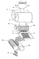
各図は本発明に用いる造粒装置の一具体例を示すものである。図1及び図2は概略斜視図である。各工程において使用する具体的設備は、成形材料の所望の粒径、配合処方、揮発分量、各処理時の温度、装置の目標処理能力等に応じて適宜選択すれば良い。
【0011】
溶融状態の熱硬化性樹脂成形材料1aを、圧延ロール2で所定厚みに圧延し、シート状成形材料1bを得る。通常、圧延ロール2は圧延された成形材料1bを強制的にロールから剥がす為のスクレイパー(図示せず)を備えている。
続いてスリッター又は溝切りロール3aで所定幅に麺状或いは所定間隔の切り込みを有する凹凸シート状に加工する。通常、溝切りロール3aは、麺状或いは凹凸シート状に加工された成形材料1cを強制的に溝切りロール3aから剥がす為のスクレイパーを備えている。またこの溝切りロール3aは、図1に示すように1対の溝切りロール3a,3aとして使う事によって最大の処理能力を有し好ましいが、図2のように溝切りロール3aとまな板ロール3bとの組合せも選択出来る。この場合、溝切りロールの刃先調整、管理やスクレイパーの機能管理が容易である。
【0012】
さらにこの麺状あるいは凹凸シート状に加工した成形材料1cを、裁断機4により次工程の切断又は切り込み処理が可能な長さに裁断し、方向転換機5により移送方向を前記第1の移送方向を90度転換した第2の移送方向に変更する。次いで、スリッター又は溝切りロール6a,6a(図1)または6a,6b(図2)に導入し、前記第2の移送方向と平行に、所定長さに切断するか或いは所定間隔の切込みを入れることによって所定の粒径を有する造状物ないしは後工程で容易に粒状に分離する凹凸シート状物1dを得る。通常溝切りロール6aは、成形材料を強制的にこの溝切りロール6aから剥がす為のスクレイパー(図示せず)を備えている。
【0013】
本発明において用いられる熱硬化性樹脂は、代表的にはフェノール樹脂であるが、このほか、エポキシ樹脂、ポリイミド樹脂、ポリエステル樹脂などを用いてもよい。フェノール樹脂においては、ノボラックフェノール樹脂の場合、硬化剤として通常ヘキサメチレンテトラミンが用いられるが、これに限定されるものではない。充填材としては、無機物ではガラス繊維、炭酸カルシウム、クレー、マイカ、シリカ等、有機物では木粉、パルプ、織物繊維、熱硬化性樹脂硬化物などが挙げられる。
【0014】
【実施例】
(実施例1)
粉末状のフェノール樹脂(ノボラック型フェノール樹脂)34重量部、粉末状の硬化剤(ヘキサメチレンテトラミン)6重量部、無機基材(ガラスチョップ45重量部、クレー10重量部)55重量部、及びその他の添加剤(硬化助剤:水酸化カルシウム2重量部、離型剤:ステアリン酸2重量部、着色剤:カーボンブラック1重量部)5重量部をブレンダーにて混合した後加熱ロールにて溶融混練した。これを直ちに80℃に温度調節したロール間隙2mmの圧延ロールに投入して圧延した。続いて、連続的にスクレイパーを備えた溝間ピッチ2mmの溝切りロール2本(ロール間隙0mm)の間を通して麺状に加工した。さらにこの麺状に加工された成形材料を、長さ400mmに裁断機にて裁断した後、方向転換機により移送方向を90度変え、スクレイパーを備えた溝間ピッチ2mmの溝切りロール2本(ロール間隙0mm)の間を通し、粒状のフェノール樹脂成形材料を製造した。
【0015】
得られた粒状の成形材料を自転式小型混合機で15分処理後、振動篩機で篩分して粒度分布を確認したところ、1〜2mmの粒径のものが95%であり、かつ180μm以下の微粉の発生は実質的になかった。
【0016】
(実施例2)
実施例1と同じ成形材料用素材をブレンダーにて混合した後加熱ロールにて溶融混練した。これを直ちに80℃に温度調節したロール間隙2mmの圧延ロールに投入して圧延した。続いて、連続的にスクレイパーを備えた溝間ピッチ2mmの溝切りロール2本(ロール間隙0.2mm)の間を通して凹凸シート状に加工した。さらにこの凹凸シート状に加工された成形材料を、長さ400mmに裁断機にて裁断した後、方向転換機により移送方向を90度変え、スクレイパーを備えた溝間ピッチ2mmの溝切りロール2本(ロール間隙0.2mm)の間を通し、大部分が凹凸シート状であるフェノール樹脂成形材料を製造した。
【0017】
得られた成形材料を自転式小型混合機で15分処理後、振動篩機で篩分して粒度分布を確認したところ、1〜2mmの粒径のものが93%であり、かつ180μm以下の微粉0.1%程度であった。
【0018】
【発明の効果】
本発明の熱硬化性樹脂成形材料の製造方法及び装置は、従来の生産方式では10%以上も発生していた微粉の発生を極限まで低減することができ、成形材料の造粒を長時間安定して行うことが可能である。従って、製品歩留りを大きく向上することができ、環境衛生上も好ましい。設備においてもシンプルでコンパクトであるので、設備投資を安価に抑えることができる。
【図面の簡単な説明】
【図1】 本発明に使用する造粒装置(一例)の概略斜視図
【図2】 本発明に使用する造粒装置(一例)の概略斜視図
【符号の説明】
1a 溶融、混練直後の熱硬化性樹脂成形材料
1b 所定の厚みに圧延された熱硬化性樹脂成形材料
1c 幅方向に麺状或いは凹凸シート状に加工された熱硬化性樹脂成形材料
1d 長さ方向に切断或いは切込み加工された熱硬化性樹脂成形材料
2 圧延ロール
3a 溝切りロール
3b まな板ロール
4 裁断機
5 方向転換機
6a 溝切りロール
6b まな板ロール[0001]
BACKGROUND OF THE INVENTION
The present invention relates to a method and an apparatus for producing a granular molding material by melting and kneading a thermosetting resin molding material such as a phenolic resin and continuously granulating it. A thermosetting resin molding material with less generation of fine powder later is provided.
[0002]
[Prior art]
Conventionally, a thermosetting resin molding material is generally taken out in a lump or a sheet after mixing, kneading, and cooling after blending raw materials, and pulverized to a certain particle size after cooling. The fine powder generated at the time of pulverization and after production decreases the yield, and the fine powder generated by vibration during packaging and transport after shipment floats as dust during handling, which is not preferable for environmental hygiene.
Further, granulation of the thermosetting resin molding material by an extrusion granulator is preferable from the viewpoint of environmental hygiene because the generation of fine powder is relatively small, but productivity is low and improvement thereof is desired.
[0003]
[Problems to be solved by the invention]
In view of the above-mentioned problems, the present invention rolls a molding material to a certain thickness with a rolling roll, performs noodle processing or uneven processing with a predetermined width in a state maintained at an appropriate temperature, and then makes a predetermined length. After cutting, this molding material is continuously cut to a predetermined length while being transferred in a direction different by 90 degrees from the previous transfer direction, or by cutting at a predetermined interval, a molding material having a desired particle size is obtained. The present invention provides a granulation method and apparatus for a thermosetting resin molding material that is capable of continuous operation for a long time and has good productivity.
[0004]
[Means for Solving the Problems]
The present invention is (1) in a method of granulating a thermosetting resin molding material, the molding material in a molten state is transferred while being rolled to a predetermined thickness, and the transfer direction along the rolling direction is defined as a first transfer direction. In this case, it is processed into a noodle shape having a predetermined width in parallel with the first transfer direction or processed into a concavo-convex sheet shape having a cut at a predetermined interval, and then this molding material can be cut or cut in the next step. After cutting to a desired length, the molding material is transferred in the direction of the second transfer obtained by changing the first transfer direction by 90 degrees, and is cut into a predetermined length in parallel with the transfer direction. (2) Rolling for rolling a molten molding material to a predetermined thickness in an apparatus for granulating a thermosetting resin molding material, characterized in that an incision is made roll, a rolled molding material pressure If the transport direction along the direction to the first transport direction, slitter for processing into uneven sheet having a cut of the first transport direction and parallel to, or predetermined intervals processed into noodles having a predetermined width Or a grooving roll, a cutting machine that cuts the molding material to a length that can be cut or cut in the next process, and the transfer direction of the molding material is changed to a second transfer direction obtained by changing the first transfer direction by 90 degrees. And a slitter or a grooving roll for cutting the molding material in a predetermined length or incising a predetermined interval in parallel with the second transfer direction. An apparatus for producing a curable resin molding material.
[0005]
In the present invention, first, the molten molding material is rolled to a thickness corresponding to the final particle shape. For this purpose, a normal rolling roll, preferably a rolling roll equipped with a temperature adjusting mechanism is used. Subsequently, it is processed into a noodle shape having a width corresponding to the final particle shape or an uneven sheet shape having cuts. Therefore, it is preferable to use a grooving roll provided with a scraper for preventing adhesion of a slitter or a molding material. Next, the molding material processed into the noodle shape or the uneven sheet shape is cut into a predetermined length that can be cut or cut in the next process, and then the transfer direction is changed by 90 degrees to make the molding material parallel to the cutting direction. In parallel with this transfer direction, a length or interval corresponding to the final particle shape is cut or incised. In this way, a molding material having a desired particle size with less generation of fine powder can be obtained.
[0006]
One of the features of the present invention is that the thermosetting resin molding material melt-kneaded by general equipment such as a kneading roll, a single-screw extruder, a twin-screw kneading extruder, a planetary kneading extruder, and a kneader is processed in the next step. Rolling with a rolling roll maintained at a temperature that maintains the softness necessary for the above. This process stabilizes the noodle-like processing or uneven processing by the slitter or grooving roll in the next process, and at the same time densifies the molding material, and its shape is not easily broken by impact or friction received in the subsequent process. A granular molding material with less generation is obtained.
Regarding the temperature control of the rolling roll, a roll with a built-in hot water or steam circuit is generally used, and the set temperature varies depending on the formulation of the molding material and the amount of volatile matter. About -130 degreeC is preferable.
[0007]
A molding material that is rolled to a predetermined thickness with a rolling roll and that has the softness necessary for noodle processing or uneven processing is transferred in a transfer direction (hereinafter referred to as the first transfer direction) by a slitter or a grooving roll. And cut into noodles in parallel with or processed into a concavo-convex sheet by incision. The shape of the molding material after this treatment is preferably noodle-like, but may be a concave-convex sheet that allows easy adjustment and management of equipment as long as it is easily separated during post-process and inter-process transfer.
[0008]
Furthermore, the molding material processed into a noodle shape or a concavo-convex sheet shape by a slitter or grooving roll has a length that can be cut or cut in the next step while maintaining the softness necessary for the next processing step. Then, the direction of the molding material is changed by 90 degrees with a direction changer, and the molding material is introduced into a slitter or a grooving roll, and is cut into a predetermined length or cut at a predetermined interval in parallel with the transfer direction. In this case as well, cutting is preferable, but an uneven sheet shape that allows easy adjustment and management of the equipment is preferable as long as it is easily separated at the time of the post-process and transfer between processes. In this manner, a molding material having a predetermined granular shape or an uneven sheet shape that can be easily granulated is obtained.
[0009]
Another feature of the granulation method of the present invention is that the molding material maintained at a temperature suitable for processing is cut or cut parallel to the transfer direction by the slitter or grooving roll, cutting, changing the transfer direction, In addition, a predetermined granular shape or an uneven sheet-shaped molding material that can be easily granulated is obtained continuously by cutting or cutting parallel to the changed transfer direction. Therefore, the obtained molding material has a smooth particle end surface, hardly breaks down due to impact, vibration, friction, etc. during the post-process or transfer, and hardly generates fine powder.
[0010]
Hereinafter, the present invention will be described with reference to the drawings.
Each figure shows a specific example of a granulating apparatus used in the present invention. 1 and 2 are schematic perspective views. The specific equipment used in each step may be appropriately selected according to the desired particle size of the molding material, the compounding recipe, the volatile content, the temperature during each process, the target processing capacity of the apparatus, and the like.
[0011]
The thermosetting
Subsequently, the sheet is processed into a noodle shape or a concavo-convex sheet having a predetermined interval with a slitter or a
[0012]
Further, the
[0013]
The thermosetting resin used in the present invention is typically a phenol resin, but an epoxy resin, a polyimide resin, a polyester resin, or the like may also be used. In the case of a phenol resin, in the case of a novolak phenol resin, hexamethylenetetramine is usually used as a curing agent, but the present invention is not limited to this. Examples of the filler include glass fiber, calcium carbonate, clay, mica, silica and the like for inorganic substances, and wood powder, pulp, woven fiber, and thermosetting resin cured substance for organic substances.
[0014]
【Example】
Example 1
34 parts by weight of powdered phenolic resin (novolak type phenolic resin), 6 parts by weight of powdered curing agent (hexamethylenetetramine), 55 parts by weight of inorganic base material (45 parts by weight of glass chop, 10 parts by weight of clay), and
[0015]
The obtained granular molding material was treated for 15 minutes with a rotary compact mixer, and then sieved with a vibration sieve to confirm the particle size distribution. As a result, the one with a particle size of 1 to 2 mm was 95% and 180 μm. The following fine powder was not substantially generated.
[0016]
(Example 2)
The same molding material as in Example 1 was mixed with a blender and then melt-kneaded with a heating roll. This was immediately put into a rolling roll having a roll gap of 2 mm whose temperature was adjusted to 80 ° C. and rolled. Subsequently, it was processed into a concavo-convex sheet through two grooving rolls having a pitch of 2 mm between grooves (roll gap 0.2 mm) equipped with a scraper. Further, the molding material processed into the concavo-convex sheet shape is cut into a length of 400 mm by a cutting machine, the transfer direction is changed by 90 degrees by a direction changing machine, and two grooving rolls having a pitch of 2 mm between grooves provided with a scraper. A phenol resin molding material, most of which is in the form of a concavo-convex sheet, was produced through the gaps (roll gap 0.2 mm).
[0017]
After processing the obtained molding material for 15 minutes with a rotary compact mixer and sieving with a vibration sieve machine to confirm the particle size distribution, the one having a particle diameter of 1 to 2 mm is 93% and 180 μm or less. The fine powder was about 0.1%.
[0018]
【The invention's effect】
The production method and apparatus of the thermosetting resin molding material of the present invention can reduce the generation of fine powder, which has been generated more than 10% in the conventional production method, to the maximum, and stable granulation of the molding material for a long time. Can be done. Therefore, the product yield can be greatly improved, which is also preferable for environmental hygiene. Since the equipment is simple and compact, capital investment can be suppressed at a low cost.
[Brief description of the drawings]
FIG. 1 is a schematic perspective view of a granulating apparatus (example) used in the present invention. FIG. 2 is a schematic perspective view of a granulating apparatus (example) used in the present invention.
1a Thermosetting
Claims (2)
Priority Applications (9)
| Application Number | Priority Date | Filing Date | Title |
|---|---|---|---|
| JP2001229053A JP3815719B2 (en) | 2000-08-01 | 2001-07-30 | Method and apparatus for producing thermosetting resin molding material |
| TW090133258A TW506885B (en) | 2001-07-30 | 2001-12-31 | Method of and apparatus for manufacturing molded materials of thermosetting resin composition |
| US10/032,066 US6838030B2 (en) | 2001-07-30 | 2001-12-31 | Method of and apparatus for manufacturing molded materials of thermosetting resin composition |
| EP02000383A EP1281497B1 (en) | 2001-07-30 | 2002-01-07 | Method and apparatus for granulating thermosetting resins |
| DE60203348T DE60203348T2 (en) | 2001-07-30 | 2002-01-07 | Method and device for the production of molded parts from heat-treated resin compounds |
| ES02000383T ES2240575T3 (en) | 2001-07-30 | 2002-01-07 | PROCEDURE AND EQUIPMENT FOR MANUFACTURING MOLDED MATERIALS OF A THERMOENDURECIBLE RESIN COMPOSITION. |
| KR1020020000951A KR100876497B1 (en) | 2001-07-30 | 2002-01-08 | Method and apparatus for producing thermosetting resin composition molding material |
| CNB021009562A CN100363162C (en) | 2001-07-30 | 2002-01-08 | Production process and apparatus for thermosetting resin composite material |
| US10/918,353 US7077640B2 (en) | 2001-07-30 | 2004-08-16 | Method of and apparatus for manufacturing molded materials of thermosetting resin composition |
Applications Claiming Priority (3)
| Application Number | Priority Date | Filing Date | Title |
|---|---|---|---|
| JP2000232841 | 2000-08-01 | ||
| JP2000-232841 | 2000-08-01 | ||
| JP2001229053A JP3815719B2 (en) | 2000-08-01 | 2001-07-30 | Method and apparatus for producing thermosetting resin molding material |
Publications (2)
| Publication Number | Publication Date |
|---|---|
| JP2002113714A JP2002113714A (en) | 2002-04-16 |
| JP3815719B2 true JP3815719B2 (en) | 2006-08-30 |
Family
ID=26597146
Family Applications (1)
| Application Number | Title | Priority Date | Filing Date |
|---|---|---|---|
| JP2001229053A Expired - Fee Related JP3815719B2 (en) | 2000-08-01 | 2001-07-30 | Method and apparatus for producing thermosetting resin molding material |
Country Status (1)
| Country | Link |
|---|---|
| JP (1) | JP3815719B2 (en) |
-
2001
- 2001-07-30 JP JP2001229053A patent/JP3815719B2/en not_active Expired - Fee Related
Also Published As
| Publication number | Publication date |
|---|---|
| JP2002113714A (en) | 2002-04-16 |
Similar Documents
| Publication | Publication Date | Title |
|---|---|---|
| US6838030B2 (en) | Method of and apparatus for manufacturing molded materials of thermosetting resin composition | |
| JP2010506760A (en) | Method and apparatus for manufacturing wood composite materials | |
| JPH0790550B2 (en) | Equipment for producing recycled pellets of waste such as PET resin film | |
| JP3815719B2 (en) | Method and apparatus for producing thermosetting resin molding material | |
| JP3910007B2 (en) | Method for producing thermosetting resin molding material | |
| JP2002059418A (en) | Method and apparatus for manufacturing thermosetting resin compound | |
| JP3815725B2 (en) | Method for producing thermosetting resin composition molding material | |
| JP2002018836A (en) | Method and apparatus for manufacturing thermosetting resin molding material | |
| JP2005335321A (en) | Production method and production equipment of resin molding material | |
| JP2002018839A (en) | Method for manufacturing thermosetting resin molding material | |
| JP2000189794A (en) | Production of water absorbing material | |
| JP4159763B2 (en) | Method and apparatus for producing thermosetting resin molding material | |
| JPH05147036A (en) | Method and apparatus for reclaiming waste plastic | |
| JP2002018837A (en) | Apparatus for granulating thermosetting resin molding material | |
| JPH0889782A (en) | Granulating device | |
| JP3948894B2 (en) | Method and apparatus for producing thermosetting resin molding material | |
| JPH0313304A (en) | Pelletizing method of thermoplastic resin | |
| JP4187806B2 (en) | Method for producing granular thermosetting resin molding material | |
| JPH04301409A (en) | Manufacture of polyvinyl alcohol base molded form | |
| JP4068787B2 (en) | Method for producing halogenated carbonate compound granule | |
| JPH10180755A (en) | Manufacture of epoxy resin composition for sealing semiconductor | |
| JP3073974U (en) | Foam mainly composed of government-made postcards | |
| JPH11293124A (en) | Waste paper material for compounding in resin, and its production | |
| JP3444177B2 (en) | Kneading granulator | |
| JPH0747544A (en) | Extuder for thermosetting resin molding material |
Legal Events
| Date | Code | Title | Description |
|---|---|---|---|
| A621 | Written request for application examination |
Free format text: JAPANESE INTERMEDIATE CODE: A621 Effective date: 20040609 |
|
| A977 | Report on retrieval |
Free format text: JAPANESE INTERMEDIATE CODE: A971007 Effective date: 20050823 |
|
| A131 | Notification of reasons for refusal |
Free format text: JAPANESE INTERMEDIATE CODE: A132 Effective date: 20060314 |
|
| A521 | Written amendment |
Free format text: JAPANESE INTERMEDIATE CODE: A523 Effective date: 20060510 |
|
| RD02 | Notification of acceptance of power of attorney |
Free format text: JAPANESE INTERMEDIATE CODE: A7422 Effective date: 20060510 |
|
| TRDD | Decision of grant or rejection written | ||
| A01 | Written decision to grant a patent or to grant a registration (utility model) |
Free format text: JAPANESE INTERMEDIATE CODE: A01 Effective date: 20060531 |
|
| A61 | First payment of annual fees (during grant procedure) |
Free format text: JAPANESE INTERMEDIATE CODE: A61 Effective date: 20060602 |
|
| R150 | Certificate of patent or registration of utility model |
Free format text: JAPANESE INTERMEDIATE CODE: R150 |
|
| FPAY | Renewal fee payment (event date is renewal date of database) |
Free format text: PAYMENT UNTIL: 20100616 Year of fee payment: 4 |
|
| FPAY | Renewal fee payment (event date is renewal date of database) |
Free format text: PAYMENT UNTIL: 20110616 Year of fee payment: 5 |
|
| FPAY | Renewal fee payment (event date is renewal date of database) |
Free format text: PAYMENT UNTIL: 20120616 Year of fee payment: 6 |
|
| FPAY | Renewal fee payment (event date is renewal date of database) |
Free format text: PAYMENT UNTIL: 20120616 Year of fee payment: 6 |
|
| FPAY | Renewal fee payment (event date is renewal date of database) |
Free format text: PAYMENT UNTIL: 20130616 Year of fee payment: 7 |
|
| FPAY | Renewal fee payment (event date is renewal date of database) |
Free format text: PAYMENT UNTIL: 20140616 Year of fee payment: 8 |
|
| LAPS | Cancellation because of no payment of annual fees |