JP3813630B2 - Saddle riding - Google Patents
Saddle riding Download PDFInfo
- Publication number
- JP3813630B2 JP3813630B2 JP2005502691A JP2005502691A JP3813630B2 JP 3813630 B2 JP3813630 B2 JP 3813630B2 JP 2005502691 A JP2005502691 A JP 2005502691A JP 2005502691 A JP2005502691 A JP 2005502691A JP 3813630 B2 JP3813630 B2 JP 3813630B2
- Authority
- JP
- Japan
- Prior art keywords
- handle
- cover
- lever
- opening
- saddle
- Prior art date
- Legal status (The legal status is an assumption and is not a legal conclusion. Google has not performed a legal analysis and makes no representation as to the accuracy of the status listed.)
- Expired - Fee Related
Links
Images


Classifications
-
- B—PERFORMING OPERATIONS; TRANSPORTING
- B62—LAND VEHICLES FOR TRAVELLING OTHERWISE THAN ON RAILS
- B62K—CYCLES; CYCLE FRAMES; CYCLE STEERING DEVICES; RIDER-OPERATED TERMINAL CONTROLS SPECIALLY ADAPTED FOR CYCLES; CYCLE AXLE SUSPENSIONS; CYCLE SIDE-CARS, FORECARS, OR THE LIKE
- B62K11/00—Motorcycles, engine-assisted cycles or motor scooters with one or two wheels
- B62K11/14—Handlebar constructions, or arrangements of controls thereon, specially adapted thereto
-
- B—PERFORMING OPERATIONS; TRANSPORTING
- B62—LAND VEHICLES FOR TRAVELLING OTHERWISE THAN ON RAILS
- B62K—CYCLES; CYCLE FRAMES; CYCLE STEERING DEVICES; RIDER-OPERATED TERMINAL CONTROLS SPECIALLY ADAPTED FOR CYCLES; CYCLE AXLE SUSPENSIONS; CYCLE SIDE-CARS, FORECARS, OR THE LIKE
- B62K21/00—Steering devices
- B62K21/12—Handlebars; Handlebar stems
Landscapes
- Engineering & Computer Science (AREA)
- Mechanical Engineering (AREA)
- Mechanical Control Devices (AREA)
- Automatic Cycles, And Cycles In General (AREA)
- Steering Devices For Bicycles And Motorcycles (AREA)
Description
この発明は、例えば、スクータ型自動二輪車に適する鞍乗り型車両に関する。 The present invention relates to a saddle-ride type vehicle suitable for, for example, a scooter type motorcycle.
一般にスクータ型自動二輪車にあっては、カバー部材によって車体フレーム全体が覆われる構造となっている。 Generally, a scooter type motorcycle has a structure in which the entire body frame is covered with a cover member.
車体フレームを覆うカバー部材として、例えば、ハンドルカバーやアンダカバー等がある。 Examples of the cover member that covers the body frame include a handle cover and an under cover.
ハンドルカバーは、ハンドルバーの左右両サイドのハンドルグリップとその前方のハンドルレバーを露出した状態でカバーするようになっている(特開平9−193865号公報(特許文献1)参照)。 The handle cover is configured to cover the handle grip on the left and right sides of the handle bar and the handle lever in front of the handle bar (see JP-A-9-193865 (Patent Document 1)).
カバー部材は、その取付けにあたって取付け性の面で優れていることと、高い外観品質が要求され、ハンドルカバーもその例外ではない。 The cover member is required to be excellent in terms of mountability and to have high appearance quality, and the handle cover is no exception.
ハンドルカバーは、特許文献1に示すように、左右両サイドのハンドルグリップ及びハンドルカバーを残してハンドルバーを覆う形状となるため、例えば、組付性の面からハンドルグリップを中心として前後から合わせることができるように前方のフロントカバーと後方のリヤカバーとに分割可能な形状をとっている。
As shown in
ハンドルグリップの領域は、ハンドルレバー及びケーブル等の配索の観点から大きく切欠開口されるようになるため、そこから、内部がみえることで高い外観品質が得られにくい面があった。また、外観品質を向上させるために別体のカバーで切欠開口の一部を覆うことも考えられるが、部品点数が増加する等、コストの面、組付性の面でも望ましくない。 The area of the handle grip is greatly opened from the viewpoint of the arrangement of handle levers, cables, and the like, and therefore, there is a surface where it is difficult to obtain high appearance quality by viewing the inside. Further, in order to improve the appearance quality, it is conceivable to cover a part of the notch opening with a separate cover, but this is not desirable in terms of cost and assembly, such as an increase in the number of parts.
この発明は、取付け時の作業性を何等損なうことなく高い外観品質が得られる鞍乗り型車両を提供することを目的としている。 It is an object of the present invention to provide a saddle-ride type vehicle that can obtain a high appearance quality without any loss in workability during installation.
前記目的を達成するために、この発明の第1のアスペクトの鞍乗り型車両は、左右両端部にハンドルグリップを有するハンドルバーと、ハンドルグリップの近傍に配置され、基部を中心に揺動するとともに運転者が操作する操作部を有する左右一対のハンドルレバーと、ハンドルグリップと上記操作部を外側に露出するようにハンドルバーを覆うハンドルカバーとを有し、上記ハンドルカバーの一端部には、一方のハンドルレバーの操作部がハンドルカバーを貫通するのを可能ならしめる孔形状の第1レバー開口部が設けられ、上記ハンドルカバーの他端部には、他方のハンドルレバーの基部を囲むように開口する切欠き形状の第2レバー開口部が設けられていることを特徴とする。 In order to achieve the above object, a saddle-ride type vehicle according to a first aspect of the present invention is disposed near a handlebar having handlebar grips at both left and right end portions, and swings around a base portion. A pair of left and right handle levers having an operation unit operated by a driver; a handle grip; and a handle cover that covers the handle bar so as to expose the operation unit to the outside. A hole-shaped first lever opening is provided to allow the handle lever operating portion to pass through the handle cover, and the other end of the handle cover opens to surround the base of the other handle lever. A notch-shaped second lever opening is provided.
これにより、ハンドルカバーの取付け時に、孔形状の第1レバー開口部を一方のハンドルレバーのレバー操作部に対して内側から外側へ向かって貫通し突出させた後、切欠開放された第2レバー開口部を他方のハンドルレバーのレバー操作部側に位置決めすることで後付け作業が可能となる。 As a result, when the handle cover is attached, the hole-shaped first lever opening is made to penetrate from the inner side to the outer side with respect to the lever operating part of one handle lever, and then the notch is opened. By positioning the part on the lever operating part side of the other handle lever, the retrofitting operation can be performed.
この場合、ハンドルカバーの一方の第1レバー開口部を、レバー操作部に対して内側から外側へ向かって貫通させればよいため何等作業性を損なうことはない。しかも、第1レバー開口部の孔形状は、最小の開口面積で済む結果、露出部分が小さく抑えられ高い外観品質が得られる。しかも、部品点数の増加を抑えることが可能である。 In this case, since one first lever opening portion of the handle cover has only to be penetrated from the inside toward the outside with respect to the lever operation portion, no workability is impaired. In addition, the hole shape of the first lever opening portion requires a minimum opening area. As a result, the exposed portion can be kept small and high appearance quality can be obtained. In addition, an increase in the number of parts can be suppressed.
また、本発明の好適実施例にあっては、油圧ブレーキ用のブレーキオイルを貯留する油ケースの少なくとも一部をハンドルカバーの内部であって第2レバー開口部を通して外部から見える位置に配置しても良い。 In the preferred embodiment of the present invention, at least a part of the oil case for storing the brake oil for the hydraulic brake is disposed inside the handle cover so as to be visible from the outside through the second lever opening. Also good.
これにより、油ケースが、切欠開放された第2レバー開口部を目隠しするカバー部材として機能するため、第2レバー開口部側の外観品質を向上させることが可能となる。しかも、部品点数の増加を抑えることが可能となる。 As a result, the oil case functions as a cover member that blinds the notched second lever opening, so that the appearance quality on the second lever opening side can be improved. In addition, an increase in the number of parts can be suppressed.
また、操作部の揺動運動を進退運動に変換する機構を備え、その機構の一部を覆うケースの少なくとも一部を、前記第2レバー開口部を通して外部から見える位置に配置しても良い。 Further, a mechanism for converting the swinging motion of the operation unit into a forward / backward motion may be provided, and at least a part of the case covering a part of the mechanism may be disposed at a position visible from the outside through the second lever opening.
これにより、操作部は例えば、スロットル機構であれば、ハンドルグリップやスロットルレバーとなる。また、冷寒時の始動性を向上させるためのチョーク機構であれば、操作部はチョークレバーとなり、これらの一部を覆うケースが、レバー開口部を目隠しするカバー部材として機能するため、切欠開放された第2レバー開口部側の外観品質を向上させることが可能となる。しかも、部品点数の増加を抑えることが可能となる。 Thus, for example, if the operation unit is a throttle mechanism, it becomes a handle grip or a throttle lever. If the choke mechanism is used to improve startability in cold weather, the operation part will be a choke lever, and the case that covers a part of these functions as a cover member that hides the lever opening. It is possible to improve the appearance quality on the second lever opening side. In addition, an increase in the number of parts can be suppressed.
また、前記第1レバー開口部の近傍に、操作スイッチを配置しても良い。 An operation switch may be disposed in the vicinity of the first lever opening.
これにより、操作スイッチの操作面以外の面、特に、ハーネスが突出した部分や操作スイッチを取付けるブラケット等が外から見えにくくなり、操作スイッチの操作面以外の面を覆う別体のカバー部材がなくても外観品質の向上が図れる。 This makes it difficult to see the surface other than the operation surface of the operation switch, in particular, the protruding part of the harness or the bracket for mounting the operation switch from the outside, and there is no separate cover member covering the surface other than the operation surface of the operation switch. However, the appearance quality can be improved.
以下、図1乃至図12の図面を参照しながらこの発明の実施の形態について具体的に説明する。 Hereinafter, embodiments of the present invention will be specifically described with reference to FIGS. 1 to 12.
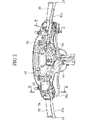
図5は鞍乗り型車両の代表例としてここではスクータ型自動二輪車の概要側面図を示している。 FIG. 5 shows a schematic side view of a scooter type motorcycle here as a typical example of a saddle-ride type vehicle.
スクータ型自動二輪車1の車体フレーム3はヘッドパイプ5から後方へ斜め下方に延びる鋼管製メインフレーム7と、メインフレーム7の後端に後方へ斜め上向きに延びる左右一対の鋼管製サイドフレーム9,9とから成る構造となっている。サイドフレーム9,9間にはスイング式動力ユニット11が上下揺動可能に枢支されている。スイング式動力ユニット11は、エンジン13及びエンジン13の左側部にVベルトドライブ式無段変速装置を内蔵する伝動ケース15を始めとしてエアクリーナ17等を一体に接続したものである。伝動ケース15の後端部に後輪19が軸支されている。また伝動ケース15と左側のサイドフレーム9との間にはリヤクッションユニット21が介設され、スイング式動力ユニット11はピポット23を中心として上下に揺動可能となっている。
The body frame 3 of the
ヘッドパイプ5には、ステアリングシャフト25が回転自在に支持され、そのステアリングシャフト25の下方には、アンダブラケット27を介してフロントフォーク29が設けられている。ステアリングシャフト25の上端には、ハンドルバー31が固定され、フロントフォーク29の下端部には前輪33が軸支されている。
A
ハンドルバー31は、左右両サイドにハンドルグリップ35を有し、その前方にはハンドルレバー37のレバー操作部37aが位置している。左右のレバー操作部37aはハンドルグリップ35と一緒に握ることで、例えば、左側にあってはブレーキケーブル39を介して後輪ブレーキ(図示していない)のブレーキ操作が可能となっている。また、右側にあっては、内部にブレーキオイルが充填されたブレーキホース41を介して前輪ブレーキ43のブレーキ操作が可能となっている。
The
ブレーキホース41を備えた右側のハンドルレバー37の基部は油ケース45等が配置され基部領域の目隠し部材として機能している。
An
ハンドルバー31は左右のハンドルグリップ35を残してハンドルカバー47により覆われている。
The
ハンドルカバー47は前カバー49と後カバー51とで構成され、各カバー端縁が閉じ合わさった状態で前記ハンドルバー31に固定支持されている。
The
後カバー51は、ハンドルバー31に固定支持されるベースカバーとなっていて、そのベースカバーとなる後カバー51に対して前カバー49が後付け可能となっている。
The
具体的に説明すると、後カバー51の一方(図1右側)は図3及び図4に示すようにハンドルバー31を挟んで後側に後カバー51が、前側に取付けブラケットがそれぞれ配置され、取付けブラケット53の上部側取付部53aには、操作スイッチ55のスイッチケース57から延長された上位側ボス部57aが後カバー51を介して接合し合い、取付けブラケット53、後カバー51、上位側ボス部57aの三者は締結ねじ59によって一体に固定支持されている。
More specifically, as shown in FIGS. 3 and 4, one of the rear covers 51 (the right side in FIG. 1) is arranged with a
取付けブラケット53の下部側取付部53bには、前記スイッチケース57から延長された下位側ボス部57bが接合し合い締結ねじ61によって固定支持されている。
A
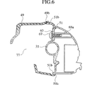
後カバー51の他方(図1左側)は、図6に示すようにハンドルバー31に溶着された支持ブラケット63に対して、後カバー51及び操作スイッチ65のボス部65aが接合され、締結ねじ67により三者一体に固定支持されている。
As shown in FIG. 6, the
さらに、後カバーは前記した左右両端の取付け位置から内側の取付部69(ここでは左右の内、片側のみ示す)が図7に示すように、後カバー51から筒状に突出し、その取付部69はハンドルバー31に溶着された支持ブラケット71に対して締結ねじ73により一体に固定支持されている。
Further, as shown in FIG. 7, the rear cover has an inner mounting portion 69 (only one of the left and right sides is shown) protruding from the mounting positions at both the left and right ends as shown in FIG. Is fixedly supported by a
前カバー49は、後カバー51に対して後付けするようになっていて、前カバー49の一方(図1右側)には前記ハンドルレバー37のレバー操作部37aを内側から外側へ向かって貫通し突出させる孔形状のレバー開口部75を有している。前カバー49の他方には、ハンドルレバー47のレバー操作部37a側に向かって切欠開口されたレバー開口部77を有している。したがって、孔形状のレバー開口部75は、前カバー49を後付けする時に、ハンドルレバー37のレバー操作部37aに対して内側から外側へ向かって貫通し、突出させる開口面積を備えていればよく、小さな開口面積で済むようになり、露出領域が小さく抑えられている。また、孔形状のレバー開口部75は、切欠開放されたレバー開口部27との組合せによって何等作業性を損なうことなく後カバー51に対する仮支持作業が容易に行なえるようになっている。
The
前カバー49の切欠開放されたレバー開口部37側は、前記した油ケース45の外に、操作子の揺動運動を進退運動に変換してケーブル78aに伝達する機構の一部を覆うケース78が位置することで見栄えの向上が図られている。なお、操作部としては、スロットル機構であれば、ハンドルグリップ35やスロットルレバー(図示していない)である。また、冷寒時の始動性を向上させるためのチョーク機構であれば、操作子はチョークレバーとなる。
The notch open lever opening 37 side of the
一方、前カバー49は、レバー開口部75をレバー操作部37aに対して内側から外側へ向け貫通し突出させた後、後カバー51に対して複数箇所にわたって固定支持されるようになっている。
On the other hand, the
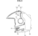
具体的には前カバー49の一方、図1、右側のD−Dの領域は、図8に示すように、後カバー51から前方へ延長された張出し部79に締結ねじ81によって一体に固定支持されている。この領域の前カバー49の上端縁は上端係合溝49aとなっていて、上端係合溝49aが後カバー51の上端係合突部51aと係合し合うことで閉じ合せ結合され、下端縁の一部は操作スイッチ55のスイッチケース57と突合せ接合されている。なお、それ以外の前カバー49の上端縁は、図示していないが、前記した係合溝49aと係合突部51aとの係合関係によって閉じ合せ結合されている。
Specifically, one area of the
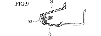
前カバー49の他方、図1、左側のE−E領域は、図9に示すように後カバー51の屈曲部と重ね合せ結合され、締結ねじ83により固定支持されている。この領域の上端縁と下端縁は図6に示すように係合凹部49bが後カバー51の係合突部51bと係合し合うことで閉じ合せ結合されている。
The other EE region on the other side of the
前カバー49の下部側F−F領域は、図10に示すように後カバー51と重ね合せ結合され、締結ねじ85により固定支持されている。
The lower side FF region of the
一方、ハンドルレバー37の下方は、フロントカバー87及びインナフェンダ89によって前面側が覆われ車体フレーム3にそれぞれ固定支持されている。フロントカバー87及びインナフェンダ89の後側は車体フレーム3を挟んでレッグシールド91によって覆われ車体フレーム3に固定支持されている。レッグシールド91の外周縁は前記フロントカバー87及びインナフェンダ89の外周縁と突合せ結合されている。
On the other hand, the lower side of the
レッグシールド91の下端は、足を乗せる低床のフットボード93が連続して配設されている。フットボード93の下部は、前記インナフェンダ89と接続連通し合うアンダカバー95が、フットボード93の後部はシート97の下方周囲を囲むようサイドカバー99がそれぞれ配設されている。
At the lower end of the
アンダカバー95は、サイドスタンド101が露出するスタンド開口孔103を有している。
The under
サイドスタンド101は、メインとなるセンタスタンド102の前方に位置し取付軸105によってサイドフレーム9の取付部107に回動自在に支持され、スタンド接地部101aがサイドフレーム7に沿う収納状態(図5実線)と外方へ突出した使用状態(図5鎖線)とに切換え操作可能となっている。
The side stand 101 is positioned in front of the
サイドスタンド101のスタンド接地部101aは、付勢ばね109によるばね圧に抗して足によって下方(図1矢印)へ回動させることで使用状態(図5鎖線)となる。また、使用状態(図5鎖線)から上方へ足によって回動させることで収納状態(図5実線)とに切換え可能となっている。
The
一方、サイドスタンド95のスタンド開口孔103は、取付け時に、収納状態にあるサイドスタンド101のスタンド接地部101aを一部領域にわたって内側から外側へ向け貫通し突出させる楕円の孔形状となっていて、開口面積が最小に抑えられている。
On the other hand, the
スタンド接地部101aが外側へ突出した突出領域は、スタンド開口孔103の開口端縁からサイド面となる一般面へ向かうテーパ面111となっていて、収納状態時のスタンド接地部101aに何等支障が起きないよう工夫されている。
The protruding area from which the
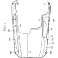
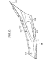
図11と図12はアンダカバー95の平面図と側面図を示したもので、アンダカバー95の前部、中間部、後部の各取付部113は、フッドボード93と締結ねじ(図示していない)によって重ね合せ結合されている。
FIGS. 11 and 12 are a plan view and a side view of the
その他の取付部は、アンダカバー95の内側に設けられた複数の係合爪孔115と、フッドボード93の係合爪(図示していない)との係合関係によって結合支持された構造となっている。
The other attachment portions are structured to be coupled and supported by the engagement relationship between a plurality of engagement claw holes 115 provided inside the
このように構成されたスクータ型自動二輪車1によれば、ハンドルカバー47を取付けるには、まず、後カバー51をハンドルバー31に取付け後、続いて前カバー49を取付ける。この場合、ハンドルバー31の前面側から前カバー49のレバー開口部75をハンドルレバー37のレバー操作部37aに位置合せした後、内側から外側へ向かって貫通させる。これによりレバー操作部37aは、ハンドルグリップ35の前方に突出するようになるから、他方の切欠開口されたレバー開口部77をもう一方のハンドルレバー37のレバー操作部37aに位置決めする。これにより、何等作業性を損なうことなく前カバーの後付け作業が可能な仮支持状態が得られるようになる。後カバー51に対する前カバー49の後付け作業完了時、一方の孔形状のレバー開口部75は開口面積が小さくて済むため、露出部分が小さく抑えられる結果、高い外観品質が得られるようになる。
According to the
反対側の切欠開口されたレバー開口部77は、ブレーキ用の油ケース45、あるいは、操作子の揺動運動を進退運動に変換する機構の一部を覆うケースが切欠開口のレバー開口部77をカバーする目隠し部材として機能するため見栄えを損なうことがなくなる。
The
一方、アンダカバー95にあっては、図5仮想線で示すように、スタンド開口孔103を収納状態にあるサイドスタンド101のスタンド接地部101aに位置合せしながら、そのスタンド接地部101aが内側から外側へ向かって貫通し突出させることで、アンダカバー95の後付け作業が可能となる。
On the other hand, in the
アンダカバー95の後付け作業完了時、孔形状のスタンド開口部103は、開口面積が小さくて済むため、露出部分が小さく抑えられる結果、高い外観品質が得られるようになる。
When the undercover 95 is retrofitted, the hole-shaped
なお、この実施形態にあっては、スクータ型自動二輪タイプについて説明したが、三輪タイプ、四輪タイプに実施することも可能である。 In addition, in this embodiment, although the scooter type motorcycle type was demonstrated, it is also possible to implement to a three-wheel type and a four-wheel type.
以上説明したように、この発明によれば、第1レバー開口部によってハンドルレバー周りの露出部分を小さく抑えることが可能となり、高い外観品質を得ることができる。しかも、第1レバー開口部の内側から外側へ向かってレバー操作部を貫通させればよいため、後付け作業にあたって何等作業性を損なうことはない。 As described above, according to the present invention, the exposed portion around the handle lever can be kept small by the first lever opening, and high appearance quality can be obtained. In addition, since it is only necessary to penetrate the lever operation part from the inside to the outside of the first lever opening, there is no loss of workability in the retrofitting work.
また、前記油ケースを第2レバー開口部を目隠しするカバー部材として機能させることが可能となるため、部品点数を増やすことなく切欠開放された第2レバー開口部側の外観品質を向上させることができる。 Moreover, since it becomes possible to make the said oil case function as a cover member which conceals the 2nd lever opening part, it can improve the external appearance quality of the 2nd lever opening part side opened notch, without increasing a number of parts. it can.
また、操作部の揺動運動を進退運動に変換する機構を覆うケースが第2レバー開口部を目隠しするカバー部材として機能させることが可能となるため、部品点数を増やすことなく切欠開放された第2レバー開口部側の外観品質を向上させることができる。 In addition, since the case covering the mechanism that converts the swinging motion of the operating portion into the forward and backward motion can function as a cover member that blinds the second lever opening, the first notch is opened without increasing the number of parts. The appearance quality on the two lever opening side can be improved.
また、第1レバー開口部からは操作スイッチの操作面以外の面、特に、ハーネスが突出している部分や操作スイッチを取付けるブラケット等が外から見えにくくなるため、操作スイッチの操作面以外の面を覆う別体のカバー部材がなくても外観品質の向上を図ることができる。 Also, from the first lever opening, the surface other than the operation surface of the operation switch, in particular, the portion where the harness protrudes and the bracket for mounting the operation switch are difficult to see from the outside. Even if there is no separate cover member to cover, the appearance quality can be improved.
また、アンダカバーのスタンド開口部を、サイドスタンドのスタンド接地部に対して内側から外側に沿って貫通させることでサイドカバーの後付け作業が可能となる。また、スタンド開口部によってスタンド周りの露出部分を小さく抑えることが可能となり、高い外観品質を得ることができる。しかも、スタンド開口部の内側から外側へ向かってスタンドを貫通させればよいため、後付け作業にあたって何等作業性を損なうことはない。 Further, the side cover can be retrofitted by penetrating the stand opening of the under cover from the inside to the outside of the stand grounding portion of the side stand. Also, the exposed portion around the stand can be kept small by the stand opening, and high appearance quality can be obtained. Moreover, since it is only necessary to penetrate the stand from the inside to the outside of the stand opening, there is no loss of workability in the retrofitting work.
また、スタンドとの干渉をさけつつスタンド開口部を奥に位置させることが可能となるため外から見えにくくなり、外観品質の向上を図ることができる。 In addition, since the stand opening can be positioned at the back while avoiding interference with the stand, it is difficult to see from the outside, and the appearance quality can be improved.
また、スタンド開口部によって、エンジン懸架部が外部から見えなくなり、外観品質の向上を図ることができる。 Further, the stand opening portion makes the engine suspension portion invisible from the outside, and the appearance quality can be improved.
Claims (4)
左右両端部にハンドルグリップを有するハンドルバーと、
ハンドルグリップの近傍に配置され、基部を中心に揺動するとともに運転者が操作する操作部を有する左右一対のハンドルレバーと、
ハンドルグリップと上記操作部を外側に露出するようにハンドルバーを覆うハンドルカバーとを有し、
上記ハンドルカバーの一端部には、一方のハンドルレバーの操作部がハンドルカバーを貫通するのを可能ならしめる孔形状の第1レバー開口部が設けられ、
上記ハンドルカバーの他端部には、他方のハンドルレバーの基部を囲むように開口する切欠き形状の第2レバー開口部が設けられていることを特徴とする鞍乗り型車両。 A saddle-ride type vehicle,
A handle bar having handle grips on both left and right ends;
A pair of left and right handle levers disposed in the vicinity of the handle grip, swinging about the base and having an operation unit operated by the driver;
A handle grip and a handle cover that covers the handle bar so as to expose the operation portion to the outside;
One end of the handle cover is provided with a hole-shaped first lever opening that enables the operation portion of one handle lever to pass through the handle cover.
A saddle-ride type vehicle characterized in that a notch-shaped second lever opening that opens to surround the base of the other handle lever is provided at the other end of the handle cover.
Applications Claiming Priority (3)
| Application Number | Priority Date | Filing Date | Title |
|---|---|---|---|
| JP2003044622 | 2003-02-21 | ||
| JP2003044622 | 2003-02-21 | ||
| PCT/JP2004/001616 WO2004074079A1 (en) | 2003-02-21 | 2004-02-16 | Saddle riding type vehicle |
Publications (2)
| Publication Number | Publication Date |
|---|---|
| JPWO2004074079A1 JPWO2004074079A1 (en) | 2006-06-01 |
| JP3813630B2 true JP3813630B2 (en) | 2006-08-23 |
Family
ID=32905458
Family Applications (1)
| Application Number | Title | Priority Date | Filing Date |
|---|---|---|---|
| JP2005502691A Expired - Fee Related JP3813630B2 (en) | 2003-02-21 | 2004-02-16 | Saddle riding |
Country Status (4)
| Country | Link |
|---|---|
| JP (1) | JP3813630B2 (en) |
| CN (1) | CN100526150C (en) |
| TW (1) | TWI247703B (en) |
| WO (1) | WO2004074079A1 (en) |
Families Citing this family (7)
| Publication number | Priority date | Publication date | Assignee | Title |
|---|---|---|---|---|
| CN101195398B (en) * | 2006-12-08 | 2010-12-22 | 光阳工业股份有限公司 | Motorcycle handle connecting seat |
| JP2013035305A (en) * | 2011-08-03 | 2013-02-21 | Yamaha Motor Co Ltd | Motorcycle |
| MY173021A (en) * | 2013-02-28 | 2019-12-19 | Honda Motor Co Ltd | Structure for front part of saddled vehicle |
| CN103192910B (en) * | 2013-04-24 | 2015-07-01 | 力帆实业(集团)股份有限公司 | Installation structure of motorcycle head covering part |
| JP6051186B2 (en) * | 2014-09-18 | 2016-12-27 | 本田技研工業株式会社 | Handle cover structure |
| WO2022074742A1 (en) * | 2020-10-06 | 2022-04-14 | ヤマハ発動機株式会社 | Saddled vehicle |
| TWI875065B (en) * | 2023-07-05 | 2025-03-01 | 三陽工業股份有限公司 | Motorcycle steering device |
Family Cites Families (4)
| Publication number | Priority date | Publication date | Assignee | Title |
|---|---|---|---|---|
| JPH0251991U (en) * | 1988-10-07 | 1990-04-13 | ||
| JP2530473Y2 (en) * | 1990-07-24 | 1997-03-26 | 本田技研工業株式会社 | Motorcycle side stand |
| JP3316885B2 (en) * | 1992-10-30 | 2002-08-19 | スズキ株式会社 | Motorcycle handle cover |
| TW495464B (en) * | 1998-02-24 | 2002-07-21 | Honda Motor Co Ltd | Vehicular steering handle |
-
2004
- 2004-02-16 CN CNB2004800003540A patent/CN100526150C/en not_active Expired - Fee Related
- 2004-02-16 WO PCT/JP2004/001616 patent/WO2004074079A1/en not_active Ceased
- 2004-02-16 JP JP2005502691A patent/JP3813630B2/en not_active Expired - Fee Related
- 2004-02-20 TW TW93104307A patent/TWI247703B/en not_active IP Right Cessation
Also Published As
| Publication number | Publication date |
|---|---|
| WO2004074079A1 (en) | 2004-09-02 |
| CN1697752A (en) | 2005-11-16 |
| TW200422224A (en) | 2004-11-01 |
| TWI247703B (en) | 2006-01-21 |
| CN100526150C (en) | 2009-08-12 |
| JPWO2004074079A1 (en) | 2006-06-01 |
Similar Documents
| Publication | Publication Date | Title |
|---|---|---|
| US8177250B2 (en) | Motorcycle body cover structure and motorcycle incorporating same | |
| US7661502B2 (en) | Parking brake system | |
| US8292021B2 (en) | Muffler assembly and pseudo muffler assembly for a motorcycle, and motorcycle incorporating the same | |
| EP1524177A2 (en) | Remote control apparatus for a scooter-type vehicle | |
| JP3813630B2 (en) | Saddle riding | |
| JP2010083358A (en) | Saddle-type vehicle | |
| JP5604124B2 (en) | Motorcycle | |
| JP4327571B2 (en) | Saddle riding type vehicle | |
| JP6728336B2 (en) | Saddle type vehicle | |
| JP2010070072A (en) | Fender structure | |
| JP5457760B2 (en) | Protective cover structure for saddle-ride type vehicle engine case | |
| JP4121405B2 (en) | Combination switch cover mounting structure for motorcycles | |
| CN110843972B (en) | Straddle type vehicle | |
| JP2005119391A (en) | Front cover structure of scooter type vehicle | |
| JP2824257B2 (en) | Motorcycle | |
| JP3433912B2 (en) | Control lever adjustment device | |
| JP6861665B2 (en) | Saddle-riding vehicle | |
| JP6761487B2 (en) | Saddle-type vehicle | |
| JP6166333B2 (en) | Harness guide structure for saddle-ride type vehicles | |
| JPH10218059A (en) | Scooter type motorcycle | |
| JP3830718B2 (en) | Saddle-type vehicle with automatic transmission | |
| JP2003312564A (en) | Motorcycle handle switch mounting structure | |
| JP7656483B2 (en) | Saddle-type vehicle | |
| JP7355857B2 (en) | saddle type vehicle | |
| JP3465446B2 (en) | Motorcycle clutch cable mounting structure |
Legal Events
| Date | Code | Title | Description |
|---|---|---|---|
| A521 | Request for written amendment filed |
Free format text: JAPANESE INTERMEDIATE CODE: A523 Effective date: 20060316 |
|
| TRDD | Decision of grant or rejection written | ||
| A01 | Written decision to grant a patent or to grant a registration (utility model) |
Free format text: JAPANESE INTERMEDIATE CODE: A01 Effective date: 20060523 |
|
| A61 | First payment of annual fees (during grant procedure) |
Free format text: JAPANESE INTERMEDIATE CODE: A61 Effective date: 20060531 |
|
| R150 | Certificate of patent or registration of utility model |
Free format text: JAPANESE INTERMEDIATE CODE: R150 |
|
| FPAY | Renewal fee payment (event date is renewal date of database) |
Free format text: PAYMENT UNTIL: 20090609 Year of fee payment: 3 |
|
| FPAY | Renewal fee payment (event date is renewal date of database) |
Free format text: PAYMENT UNTIL: 20100609 Year of fee payment: 4 |
|
| LAPS | Cancellation because of no payment of annual fees |