JP3811552B2 - Heavy duty pneumatic radial tire - Google Patents
Heavy duty pneumatic radial tire Download PDFInfo
- Publication number
- JP3811552B2 JP3811552B2 JP25401097A JP25401097A JP3811552B2 JP 3811552 B2 JP3811552 B2 JP 3811552B2 JP 25401097 A JP25401097 A JP 25401097A JP 25401097 A JP25401097 A JP 25401097A JP 3811552 B2 JP3811552 B2 JP 3811552B2
- Authority
- JP
- Japan
- Prior art keywords
- tire
- reinforcing layer
- short fiber
- rubber
- short fibers
- Prior art date
- Legal status (The legal status is an assumption and is not a legal conclusion. Google has not performed a legal analysis and makes no representation as to the accuracy of the status listed.)
- Expired - Fee Related
Links
Images


Landscapes
- Tires In General (AREA)
- Tyre Moulding (AREA)
- Compositions Of Macromolecular Compounds (AREA)
Description
【0001】
【発明の属する技術分野】
本発明は、トラック・バス等の重荷重車両に使用される重荷重用空気入りラジアルタイヤに関し、さらに詳しくは、ビード部におけるゴムボリュームを削減しつつ耐久性を向上するようにした重荷重用空気入りラジアルタイヤに関する。
【0002】
【従来の技術】
近年、高速道路の発達及び自動車性能の向上に伴って、重荷重車両による高速・高荷重での長時間走行が増加している。そのため、重荷重用空気入りラジアルタイヤも長時間の高速走行に耐え得るように耐久性を大幅に向上することが要求されている。また、重荷重用空気入りラジアルタイヤでは、上記耐久性の向上に加えて、燃費の低減のために軽量化が要求されている。
【0003】
従来、耐久性に優れた重荷重用空気入りラジアルタイヤとして、ビード部にスチールコードからなる補強層や有機繊維コードからなる補強層を付加したものが提案されている。しかしながら、上記のような補強構造を形成した場合であっても、カーカス層の巻き上げ端部に生じるコード間の剥離を抑制することはできなかった。
【0004】
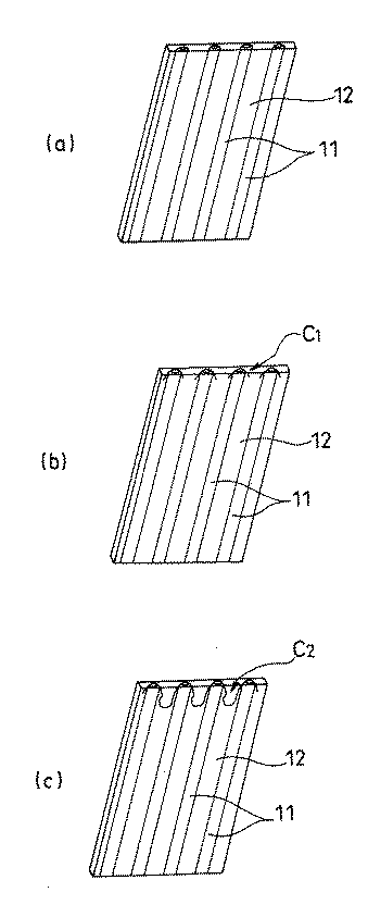
即ち、図4(a)に示すように、カーカス層の巻き上げ端部にはカーカスコード11とゴム12との未接着部分が存在するため、図4(b)のように未接着部分を起点として亀裂C1 を生じやすく、この亀裂C1 が図4(c)のように大きな亀裂C2 に成長してカーカスコード11,11間に剥離を生じるのである。また、カーカス層の巻き上げ端部をゴム補強層によって補強することも可能であるが、ゴム補強層では効果的な補強を行なうことができず、単に重量増加を招くだけであった。
【0005】
【発明が解決しようとする課題】
本発明の目的は、ビード部におけるゴムボリュームを削減しつつ耐久性を向上するようにした重荷重用空気入りラジアルタイヤを提供することにある。
【0006】
【課題を解決するための手段】
【0007】
上記目的を達成するための本発明の重荷重用空気入りラジアルタイヤは、左右一対のビード部間に複数本のカーカスコードをタイヤ径方向に配列してなるカーカス層を装架し、該カーカス層のタイヤ幅方向両端部をビードコアの廻りにタイヤ内側から外側へ巻き上げた重荷重用空気入りラジアルタイヤにおいて、少なくとも前記カーカス層の巻き上げ端部に短繊維補強層を配置し、該短繊維補強層を構成するゴム中に、少なくとも2種類のポリマーが横断面で海島構造をなす短繊維(A)がフィブリル化した短繊維(A’)と、主鎖にアミド基を有する熱可塑性ポリマーからなる短繊維(B)がゴム及び/又はポリオレフィンからなるマトリックス中に分散して結合した組成物とを、それぞれゴム100重量部に対して前記短繊維(A’)が0.5〜10重量部、前記短繊維(B)が1〜15重量部となるように配合し、これら短繊維(A’)及び短繊維(B)をタイヤ周方向に配向させて、前記短繊維補強層のタイヤ径方向のモジュラスaに対するタイヤ周方向のモジュラスbの比b/aを1.2以上にしたことを特徴とするものである。
【0008】
このようにタイヤ周方向のモジュラスbをタイヤ径方向のモジュラスaに比べて特定の比率以上に大きくした異方性ゴムからなる短繊維補強層をカーカス層の巻き上げ端部に配置することにより、タイヤ径方向に配列したコードのタイヤ周方向の動きを効果的に抑制することが可能になるので、ビード部におけるゴムボリュームを削減しつつ巻き上げ端部における応力集中を緩和し、コード間の剥離を抑制してタイヤの耐久性を向上することができる。また、複数本のスチールコードをタイヤ径方向に配列してなるスチールコード補強層をビード部におけるカーカス層に沿うように配置した場合は、該スチールコード補強層の上端部に上記短繊維補強層を配置するようにすれば、スチールコード補強層に上端部におけるコード間の剥離も抑制することができる。
【0009】
本発明において、モジュラスは20℃における20%伸長時のモジュラス(以下、20%モジュラスという)を意味する。タイヤは通常50%以下の歪み域で使用されるため、20%モジュラスに基づく低伸長時のゴム特性はタイヤ性能と相関しやすく、この20%モジュラスについて異方性を持たせることによりタイヤを効果的に補強することができる。
【0010】
20%モジュラスは、JIS K6301に規定される低伸長応力試験法によって測定することが可能である。この低伸長応力試験法では、幅5mm、長さ100mm、厚さ2mm、標線間40mmの試験片を用い、予備荷加として試験しようとする伸長率(20%)の1.5倍の伸長を2回、45±15mm/分の速度で行った後、本試験を予備荷加と同一速度で20%伸長させて停止し、30秒後に荷重を測定する。20%伸長応力(モジュラス)は以下の式により求めることができる。なお、測定は通常4回行い、その平均値を用いる。
【0011】
σ20=F20/S
σ20:20%伸長応力(MPa)
F20:20%伸長時の荷重(N)
S :試験片の断面積
上記短繊維補強層の異方性は、ゴム中に少なくとも2種類のポリマーが横断面で海島構造をなす短繊維(A)がフィブリル化した短繊維(A’)を特定量配合し、この短繊維(A’)をタイヤ周方向に配向させることにより得られる。このフィブリル化した短繊維(A’)は、短繊維補強層の20%モジュラスを飛躍的に増大させることが可能である。また、フィブリル化した短繊維(A’)に加えて、主鎖にアミド基を有する熱可塑性ポリマーからなる短繊維(B)がゴム及び/又はポリオレフィンからなるマトリックス中に分散して結合したゴム組成物を特定量配合し、これら短繊維(A’)及び短繊維(B)をタイヤ周方向に配向させるようにしたハイブリッド配合とする。
【0012】
【発明の実施の形態】
以下、本発明の構成について添付の図面を参照して詳細に説明する。
図1は本発明の実施形態からなる重荷重用空気入りラジアルタイヤのビード部を例示するものであり、図2はそのカーカス層の巻き上げ部を示すものである。図において、左右一対のビード部1,1間には複数本のカーカスコードをタイヤ径方向に配列してなるカーカス層2が装架されており、このカーカス層2のタイヤ幅方向両端部がビードコア3の廻りにタイヤ内側から外側へ巻き上げられている。また、ビードコア3の径方向外側には硬質ゴムからなるビードフィラー4が取り付けられており、カーカス層2の巻き上げ部がビードフィラー4を包み込むようになっている。
【0013】
ビード部1には複数本のスチールコードをタイヤ径方向に配列してなるスチールコード補強層5がカーカス層2に沿うように配置されており、このスチールコード補強層5のタイヤ外側の上端部がカーカス層2の巻き上げ部の近傍で終端している。カーカス層2の巻き上げ部及びスチールコード補強層5の上端部には、これら端部を被覆するエッジカバーとして短繊維補強層6が取り付けられている。また、ビード部1において、カーカス層2の巻き上げ部及びスチールコード補強層5の上端部のタイヤ外側には、複数本の有機繊維コード(ナイロンコード等)をタイヤ径方向に対して傾斜するように配列してなる有機繊維コード補強層7が配置されている。
【0014】
短繊維補強層6を構成するゴム中には、少なくとも2種類のポリマーが横断面で海島構造をなす短繊維(A)がフィブリル化した短繊維(A’)を配合し、また、主鎖にアミド基を有する熱可塑性ポリマーからなる短繊維(B)を配合し、これらハイブリッド配合した短繊維(A’)と短繊維(B)をタイヤ周方向に配向させることにより、短繊維補強層6のタイヤ径方向のモジュラスaに対するタイヤ周方向のモジュラスbの比b/aが1.2以上になるように設定されている。
【0015】
このように異方性を持たせた短繊維補強層6をカーカス層2の巻き上げ部とスチールコード補強層5の上端部に配置することにより、タイヤ径方向に配列したコードのタイヤ周方向の動きを効果的に抑制することが可能になるので、ビード部1におけるゴムボリュームを削減しつつカーカス層2の巻き上げ端部とスチールコード補強層5の上端部における応力集中を緩和し、コード間の剥離を抑制してタイヤの耐久性を向上することができる。
【0016】
図3は本発明の他の実施形態からなる重荷重用空気入りラジアルタイヤのビード部を例示するものである。なお、本実施形態において、図1と同一物には同一符号を付してその詳細な説明は省略する。図において、カーカス層2の巻き上げ端部には短繊維補強層6が配置されている。この短繊維補強層6は、ビードフィラー4と有機繊維コード補強層7との間に位置し、かつスチールコード補強層5の上端部からタイヤ径方向外側へ60mm以内の領域にビード部1の補強体として配置されている。
【0017】
このようにカーカス層2の巻き上げ端部近傍からタイヤ径方向外側へ延長する領域に異方性を持たせた短繊維補強層6を配置することにより、上記実施形態と同様にタイヤ耐久性の向上が可能であると共に、ビード部1のゴムボリュームを削減しつつ優れた操縦安定性を確保することができる。
本発明では、短繊維補強層6を少なくともカーカス層2の巻き上げ端部近傍に配置することが必要であるが、その配置形態は特に限定されることはなく、エッジカバーとして使用したり、操縦安定性を確保するための補強体として使用することが可能である。
【0018】
本発明において、短繊維補強層6のタイヤ径方向のモジュラスaに対するタイヤ周方向のモジュラスbの比b/aは1.2以上、好ましくは1.5以上にする必要がある。この比b/aが1.2未満であると有効な補強効果を得ることが困難になる。また、比b/aはゴムの硬さ、短繊維の配合量及び短繊維補強層6の押出方法等によって決まるものであり、その上限は10程度である。
【0019】
短繊維補強層6は少なくとも1種のゴムから構成されている。このゴムとしては特に限定されるものではないが、例えば、ジエン系ゴム及びその水添物〔例えば、天然ゴム(NR)、ポリイソプレンゴム(IR)、エポキシ化天然ゴム(ENR)、スチレン−ブタジエン共重合体ゴム(SBR)、ポリブタジエンゴム(高シスBR及び低シスBR)、ニトリルゴム(NBR)、水素化NBR、水素化SBR〕、各種エラストマー、例えば、オレフィン系ゴム〔例えば、エチレンプロピレンゴム(EPDM、EPM)、マレイン酸変性エチレンプロピレンゴム(M−EPM)、ブチルゴム(IIR)、イソブチレンと芳香族ビニル又はジエン系モノマー共重合体〕、含ハロゲン系ゴム〔例えば、臭素化ブチルゴム(Br−IIR)、塩素化ブチルゴム(Cl−IIR)、イソブチレンパラメチルスチレン共重合体の臭素化物(Br−IPMS)、クロロスルホン化ポリエチレン(CMS)、塩素化ポリエチレン(CM)、マレイン酸変性塩素化ポリエチレン(M−CM)〕、熱可塑性エラストマー〔例えば、スチレン系エラストマー、オレフィン系エラストマー、エステル系エラストマー〕等を挙げることができる。
【0020】
一方、短繊維(A)を構成するポリマーは特に限定されるものではないが、少なくとも2種類のポリマーが相溶することなく繊維横断面で海島構造を形成し、機械的剪断力によって海成分と島成分とが少なくとも部分的にバラバラに分離してフィブリル化可能な特性を持っていることが必要である。短繊維(A)を構成するポリマーとしては、ポリエステル、ポリビニルアルコール、ナイロン、ポリエチレン、ポリプロピレン、セルロース、ポリブタジエン、芳香族ポリアミド、レーヨン、ポリアリレート、ポリパラフェニレンベンズビスオキサゾール、ポリパラフェニレンベンズビスチアゾール等を挙げることができる。
【0021】
上述のようにフィブリル化可能な短繊維(A)を用いることにより、繊維添加時には短繊維のアスペクト比(繊維長を繊維断面積相当の円の直径で割った値)を低くし、繊維の絡み合いを抑制してゴムへの分散性を良好にし、その後に機械的剪断力を与えて短繊維の海成分と島成分とをバラバラに分離させてフィブリル化し、そのフィブリル化後の短繊維(A’)とゴムとの接触面積を増大させることにより、短繊維補強層6の補強効果を向上することができる。なお、短繊維(A)はフィブリル化によって全断面で分割・細径化していてもよく、或いは幹部を残して周囲や両端部だけが細径化していてもよい。
【0022】
短繊維(A)の平均長は1〜5000μmであることが好ましい。短繊維(A)の平均長が1μm未満であるとゴムの異方性が十分に得られず、逆に5000μmを超えると混練時及び押出時における加工性が著しく低下する。また、フィブリル化した短繊維(A’)の平均直径は0.05〜5.0μm、より好ましくは0.1〜2μmにすることが好ましい。フィブリル化した短繊維(A’)の平均直径を0.05μm未満にすると混練時間が長くなり、それ以上に細径化しても補強効果の向上は得られなくなり、逆に5.0μmを超えた状態にするとフィブリル化が不十分であるためゴムとの親和性が不十分になり、短繊維補強層6に亀裂を生じやすくなる。
【0023】
本発明に使用される短繊維(A)の好ましい一例として、少なくともポリビニルアルコール系ポリマー(X)と水不溶性ポリマー(Y)からなり、重量比X/Yを90/10〜20/80として、いずれか一方が島成分、他方が海成分となる海島構造を形成する短繊維を使用することができる。この短繊維は、水溶性ポリマーであるポリビニルアルコール系ポリマー(X)と、酢酸セルロースや澱粉等のように常温水中に浸漬しても溶解しない水不溶性ポリマー(Y)との組み合わせによって海島構造を形成するものである。ポリビニルアルコール系ポリマーは高強度であると共に、ゴムとの親和性が優れている。上記短繊維においてポリビニルアルコール系ポリマー(X)が90重量%を超えるとゴム混練によって機械的剪断力を与えても繊維が分割せず、逆に20重量%未満であると繊維補強効果が得られない。
【0024】
短繊維補強層6を構成するゴムに対して、フィブリル化した短繊維(A’)を単独で使用する場合、ゴム100重量部に対して0.5〜15重量部配合するようにする。短繊維(A’)の配合量が0.5重量部未満であると短繊維補強層6のタイヤ径方向のモジュラスaに対するタイヤ周方向のモジュラスbの比b/aを1.2以上にすることが困難になり、逆に15重量部を超えると混練時及び押出時における加工性が著しく低下してしまう。なお、短繊維(A)の配合量はフィブリル化した短繊維(A’)の配合量と実質的に同一である。
【0025】
短繊維(A)をゴムに配合する際、繊維の収束性を高めてゴムへの分散を促進するために、短繊維(A)の表面に、例えばゴムラテックス、液状ゴム、液状樹脂、水溶性樹脂、熱可塑性樹脂などで適当な浸漬処理を施しても良い。また、短繊維(A)とゴムとの加硫接着性を向上するために、ゴムにフェノール系化合物とメチレン供与体のような接着性化合物を配合しても良い。
【0026】
フェノール系化合物としては、レゾルシン、β−ナフトール、レゾルシンとアルデヒド類との縮合物(レゾルシン樹脂)、m−クレゾールとアルデヒド類との縮合物(m−クレゾール樹脂)、フェノールとアルデヒド類との縮合物(フェノール樹脂)、その他フェノール性有機化合物とアルデヒド類との縮合物が挙げられる。一方、メチレン供与体としては、ヘキサメチレンテトラミン、ヘキサメトキシメチロールメラミン、パラホルムアルデヒド、アセトアルデヒドアンモニア、α−ポリオキシメチレン、多価メチロールアセチレン尿素及びそれらの誘導体が挙げられる。
【0027】
フィブリル化した短繊維(A’)は、ゴムとの親和性に優れるため、これらを配合しなくても問題とはならないが、配合する場合はフェノール性化合物をゴム100重量部に対して10重量部以下、好ましくは6重量部以下とし、メチレン供与体をゴム100重量部に対して10重量部以下、好ましくは5重量部以下とすることが好ましい。これら配合量を超えると加工性が低下したり、破断伸びが著しく低下するので好ましくない。これら配合剤のほか、シランカップリング剤、チタネートカップリング剤、不飽和カルボン酸及びその誘導体、エポキシ樹脂、エポシキ基変性液状オリゴマー又はポリマー、無水マレイン酸変性液状オリゴマー又はポリマー、ブロックイソシアネートなどの接着性化合物を配合するようにしても良い。
【0028】
また、上記フィブリル化した短繊維(A’)は特に低伸長時におけるモジュラスを増大させる作用は大きいが、高伸長時におけるモジュラスを増大させる作用は小さい。そのため、フィブリル化した短繊維(A’)に加えて、主鎖にアミド基を有する熱可塑性ポリマーからなる短繊維(B)を配合する。この短繊維(B)は高伸長時におけるモジュラスを増大させる作用が大きいため、短繊維(A’)と短繊維(B)とのハイブリッド配合にすることにより、低伸長時と高伸長時におけるモジュラスを同時に増大させることが可能になる。高伸長時におけるモジュラスを増大させることにより、屈曲疲労に対する亀裂の発生及び亀裂成長を抑制することが可能になるので、耐屈曲疲労性を向上することができる。
【0029】
このようにハイブリッド配合とした場合、フィブリル化した短繊維(A’)の配合量をゴム100重量部に対して0.5〜10重量部にすると共に、主鎖にアミド基を有する熱可塑性ポリマーからなる短繊維(B)の配合量をゴム100重量部に対して1〜15重量部にする。短繊維(A’)と短繊維(B)の配合量の和が1.5重量部未満であると短繊維補強層6のタイヤ径方向のモジュラスaに対するタイヤ周方向のモジュラスbの比b/aを1.2以上にすることが困難になり、逆に25重量部を超えると混練時及び押出時における加工性が著しく低下してしまう。
【0030】
上述の短繊維(B)は主鎖にアミド基を有する熱可塑性ポリマーから構成されている。短繊維(B)の平均直径は0.05〜5.0μmの範囲にすることが好ましい。この短繊維(B)を短繊維補強層6のゴム中に配合するに当たって、短繊維(B)がゴム及び/又はポリオレフィンからなるマトリックス中に分散しており、かつ短繊維(B)がマトリックスと結合している組成物を作製し、この組成物を短繊維補強層6のゴム中に配合するようにする。短繊維(B)を含む組成物の例としては、下記の(i)、(ii) 、(iii) を挙げることができる。
【0031】
(i)加硫可能なゴム100重量部にポリマーの分子中アミド基を有する熱可塑性ポリマーの微細な短繊維1〜100重量部が埋封されており、かつ該繊維の界面において前記ポリマーと加硫可能なゴムとがノボラック型フェノールホルムアルデヒド系樹脂の初期縮合物を介してグラフトしている強化ゴム組成物(特開昭59−43041号公報参照)。
【0032】
ノボラック型フェノールホルムアルデヒド系樹脂の初期縮合物は、例えば、硫酸、塩酸、リン酸、シュウ酸などの酸を触媒として、フェノール、ビスフェノール類などのフェノール類とホルムアルデヒド(パラホルムアルデヒドでもよい)とを縮合反応させることよって得られる可溶可融の樹脂およびその変形物(変性物)である。
【0033】
(ii) ポリオレフィンとエラストマーからなるマトリックス中に、熱可塑性ポリアミドが微細繊維状に分散しており、該微細繊維がシランカップリング剤を介してマトリックスと結合している繊維強化熱可塑性組成物(特開平7−278360号公報参照)。
シランカップリング剤としては、具体的には、ビニルトリメトキシシラン、ビニルトリエトキシシラン、ビニルトリス(β−メトキシエトキシ)シラン等のビニルアルコキシシラン、ビニルトリアセチルシラン、γ−メタクリロキシプロピルトリメトキシシラン、γ−〔N−(β−メタクリロキシエチル)−N、N−ジメチルアンモニウム(クロライド)〕プロピルメトキシシラン、N−β(アミノエチル)γ−アミノプロピルトリメトキシシラン、及びスチリルジアミノシラン、γ−ウレイドプロピルトリエトキシシラン等を挙げることができる。
【0034】
(iii)加硫可能なゴム100重量部に平均径0.05〜0.8μmのナイロンの微細な繊維1〜70重量部が埋封されており、かつ該繊維の界面においてナイロンと加硫可能なゴムとがレゾール型アルキルフェノールホルムアルデヒド系樹脂の初期縮合物を介してグラフト結合している強化ゴム組成物(特開昭58−79037号公報参照)。
【0035】
レゾール型アルキルフェノールホルムアルデヒド系樹脂の初期縮合物は、例えば、クレゾールのようなアルキルフェノールとホルムアルデヒドあるいはアトセアルデヒドとをアルカリ触媒の存在下に反応させて得られるレゾール型初期縮合物およびその変性物が挙げられる。特に、アルキルフェノールホルムアルデヒド系樹脂として、分子中にメチロール基を2個以上有するものが好適に使用できる。
【0036】
上記(i)、(iii) における加硫可能なゴム、上記(ii) におけるエラストマーは、それぞれ短繊維補強層6を構成するゴムと同様なものである。また、上記(i)におけるアミド基を有する熱可塑性ポリマー、上記(ii)における熱可塑性ポリアミドとしては、熱可塑性ポリアミド及び尿素樹脂が挙げられる。これらのうち好ましいものとしては、融点が135℃から350℃のものが挙げられ、特に好ましいものとして融点が150℃から300℃の熱可塑性ポリアミドが挙げられる。
【0037】
熱可塑性ポリアミドとしては、ナイロン6、ナイロン66、ナイロン6−ナイロン66共重合体、ナイロン610、ナイロン612、ナイロン46、ナイロン11、ナイロン12、ナイロンMXD6、キシリレンジアミンとアジピン酸との重縮合体、キシリレンジアミンとピメリン酸との重縮合体、キシリレンジアミンとスペリン酸との重縮合体、キシリレンジアミンとアゼライン酸との重縮合体、キシリレンジアミンとセバシン酸との重縮合体、テトラメチレンジアミンとテレフタル酸の重縮合体、ヘキサメチレンジアミンとテレフタル酸の重縮合体、オクタメチレンジアミンとテレフタル酸の重縮合体、トリメチルヘキサメチレンジアミンとテレフタル酸の重縮合体、デカメチレンジアミンとテレフタル酸の重縮合体ウンデカメチレンジアミンとテレフタル酸の重縮合体、ドデカメチレンジアミンとテレフタル酸の重縮合体、テトラメチレンジアミンとイソフタル酸の重縮合体ヘキサメチレンジアミンとイソフタル酸の重縮合体、オクタメチレンジアミンとイソフタル酸の重縮合体、トリメチルヘキサメチレンジアミンとイソフタル酸の重縮合体、デカメチレンジアミンとイソフタル酸の重縮合体、ウンデカメチレンジアミンとイソフタル酸の重縮合体、及びドデカメチレンジアミンとイソフタル酸の重縮合体等が挙げられる。
【0038】
これらの熱可塑性ポリアミドのうち、特に好ましいものとしては、融点160〜265℃の熱可塑性ポリアミドが挙げられ、具体的にはナイロン6、ナイロン66、ナイロン6−ナイロン66共重合体、ナイロン610、ナイロン612、ナイロン46、ナイロン11、及びナイロン12等が挙げられる。
上記(ii)におけるポリオレフィンは、80〜250℃の融点を有するものである。また、50℃以上の軟化点、特に50〜200℃軟化点をもつものも好ましく用いられる。このようなポリオレフィンとしては、C2 〜C8 のオレフィンの単独重合体や共重合体、及び、C2 〜C8 のオレフィンとスチレンやクロロスチレン、α−メチルスチレン等の芳香族ビニル化合物との共重合体、C2 〜C8 のオレフィンと酢酸ビニルとの共重合体、C2 〜C8 のオレフィンとアクリル酸或いはそのエステルとの共重合体、C2 〜C8 のオレフィンのオレフィンとメタアクリル酸或いはそのエステルとの共重合体、及びC2 〜C8 のオレフィンとビニルシラン化合物との共重合体が好ましく用いられるものとして挙げられる。
【0039】
具体的には、例えば、高密度ポリエチレン、低密度ポリエチレン、ポリプロピレン、エチレン・プロピレンブロック共重合体、エチレンプロピレンランダム共重合体、線状低密度ポリエチレン、ポリ4−メチルペンテン−1、ポリブテン−1、ポリヘキセン−1、エチレン・酢酸ビニル共重合体、エチレン・アクリル酸共重合体、エチレン・アクリル酸メチル共重合体、エチレン・アクリル酸エチル共重合体、エチレン・アクリル酸プロピル共重合体、エチレン・アクリル酸ブチル共重合体、エチレン・アクリル酸2−エチルヘキシル共重合体、エチレン・アクリル酸ヒドロキシエチル共重合体、エチレン・ビニルトリメトキシシラン共重合体、エチレンビニルトリエトキシシラン共重合体、エチレン・ビニルシラン共重合体、エチレン・スチレン共重合体、及びプロピレン・スチレン共重合体、等がある。また、塩素化ポリエチレンや臭素化ポリエチレン、クロロスルホン化ポリエチレン等のハロゲン化ポリオレフィンも好ましく用いられる。これらのポリオレフィンは1種のみ用いてもよく、2種以上を組み合わせてもよい。
【0040】
次に、本発明における短繊維補強層の成形方法について説明する。先ず、ゴム中にカーボンブラック、加硫剤、加硫促進剤、プロセスオイル等を配合したゴム組成物に、少なくとも2種類のポリマーが横断面で海島構造をなす短繊維(A)を所定量配合し、更に必要に応じて、主鎖にアミド基を有する熱可塑性ポリマーからなる短繊維(B)がマトリックス中に分散して結合した組成物を所定量配合し、これをバンバリーで素練りすることにより、ゴム中に短繊維(A)及び短繊維(B)を均一に分散させる。
【0041】
次に、素練りした組成物を更に一対のオープンロール間で機械的剪断力を与えながら混練することにより短繊維(A)をフィブリル化し、フィブリル化後における短繊維(A’)の平均径を0.05〜5.0μmにする。このようにして得た組成物を押出機等を使用してタイヤ周方向に押し出してシート状に成形することにより、短繊維(A’)及び短繊維(B)をタイヤ周方向に配向させて、短繊維補強層のタイヤ径方向のモジュラスaに対するタイヤ周方向のモジュラスbの比b/aを1.2以上にすることができる。
【0042】
【実施例】
タイヤサイズを11R22.5 14PRとし、左右一対のビード部間に複数本のカーカスコードをタイヤ径方向に配列してなるカーカス層を装架し、該カーカス層のタイヤ幅方向両端部をビードコアの廻りにタイヤ内側から外側へ巻き上げた重荷重用空気入りラジアルタイヤにおいて、少なくともカーカス層の巻き上げ端部に短繊維補強層を配置した参考タイヤ1〜3及び本発明タイヤ1〜4と、短繊維補強層の替わりにゴム補強層を配置した従来タイヤを製作した。
【0043】
参考タイヤ1〜3及び本発明タイヤ1〜4において、短繊維補強層を構成するゴム中に、ポリビニルアルコールと酢酸セルロースからなる横断面で海島構造の短繊維(A)がフィブリル化した短繊維(A’)を配合し、更に必要に応じて、主鎖にアミド基を有するナイロン6からなる短繊維(B)がゴムマトリックス中に分散して結合した組成物を配合し、短繊維(A’)及び短繊維(B)をタイヤ周方向に配向させて、短繊維補強層のタイヤ径方向のモジュラスaに対するタイヤ周方向のモジュラスbの比b/aを種々異ならせた。また、参考タイヤ1〜3及び本発明タイヤ1〜4において、短繊維(A)及び短繊維(B)の配合量をゴム100重量部に対して種々異ならせた。
【0044】
これら試験タイヤについて、下記試験方法により高速耐久性を評価し、その結果を表1に示した。
高速耐久性:
試験タイヤを空気圧700kPaとしてドラム試験機に装着し、JIS D4230に準拠して高速耐久性試験を行ない、ビード部に故障を生じるまでの走行距離を測定した。評価結果は従来タイヤを100とする指数で示した。この指数値が大きいほど高速耐久性が優れている。
【0045】
【表1】
この表1から明らかなように、参考タイヤ1〜3及び本発明タイヤ1〜4は、いずれもビード部におけるゴムボリュームが従来タイヤと同等でありながら、従来タイヤに比べて高速耐久性を大幅に向上することができた。特に、本発明タイヤ1〜4のように短繊維(A)と短繊維(B)とをハイブリッド配合とした場合に耐久性の向上が顕著に現れていた。
【0047】
【発明の効果】
以上説明したように本発明によれば、左右一対のビード部間に複数本のカーカスコードをタイヤ径方向に配列してなるカーカス層を装架し、該カーカス層のタイヤ幅方向両端部をビードコアの廻りにタイヤ内側から外側へ巻き上げた重荷重用空気入りラジアルタイヤにおいて、少なくとも前記カーカス層の巻き上げ端部に短繊維補強層を配置し、該短繊維補強層を構成するゴム中に、少なくとも2種類のポリマーが横断面で海島構造をなす短繊維(A)がフィブリル化した短繊維(A’)を特定量配合し、更に、主鎖にアミド基を有する熱可塑性ポリマーからなる短繊維(B)がゴム及び/又はポリオレフィンからなるマトリックス中に分散して結合した組成物を特定量配合し、前記短繊維(A’)と短繊維(B)をタイヤ周方向に配向させて、前記短繊維補強層のタイヤ径方向のモジュラスaに対するタイヤ周方向のモジュラスbの比b/aを1.2以上にしたことにより、タイヤ径方向に配列したコードのタイヤ周方向の動きを効果的に抑制することが可能になるので、ビード部におけるゴムボリュームを削減しつつ巻き上げ端部における応力集中を緩和し、コード間の剥離を抑制してタイヤの耐久性を向上することができる。
【図面の簡単な説明】
【図1】本発明の実施形態からなる重荷重用空気入りラジアルタイヤのビード部を例示する断面図である。
【図2】図1におけるカーカス層の巻き上げ部を示す斜視図である。
【図3】本発明の他の実施形態からなる重荷重用空気入りラジアルタイヤのビード部を例示する断面図である。
【図4】(a)〜(c)は従来の重荷重用空気入りラジアルタイヤのカーカス層の巻き上げ端部におけるコード間剥離の発生メカニズムを示す斜視図である。
【符号の説明】
1 ビード部
2 カーカス層
3 ビードコア
4 ビードフィラー
5 スチールコード補強層
6 短繊維補強層
7 有機繊維コード補強層[0001]
BACKGROUND OF THE INVENTION
The present invention relates to a heavy-duty pneumatic radial tire used in heavy-duty vehicles such as trucks and buses. More specifically, the present invention relates to a heavy-duty pneumatic radial tire that improves durability while reducing rubber volume in a bead portion. Regarding tires.
[0002]
[Prior art]
In recent years, with the development of highways and the improvement of automobile performance, long-time running at high speeds and high loads by heavy-duty vehicles is increasing. For this reason, it is required that the heavy-duty pneumatic radial tire be significantly improved in durability so that it can withstand high-speed running for a long time. Further, in the heavy-duty pneumatic radial tire, in addition to the above-described improvement in durability, weight reduction is required in order to reduce fuel consumption.
[0003]
Conventionally, a heavy-duty pneumatic radial tire excellent in durability has been proposed in which a reinforcement layer made of a steel cord or a reinforcement layer made of an organic fiber cord is added to a bead portion. However, even when the reinforcing structure as described above is formed, it is not possible to suppress the separation between the cords generated at the winding end of the carcass layer.
[0004]
That is, as shown in FIG. 4A, there is an unbonded portion between the
[0005]
[Problems to be solved by the invention]
An object of the present invention is to provide a heavy-duty pneumatic radial tire that improves the durability while reducing the rubber volume in the bead portion.
[0006]
[Means for Solving the Problems]
[0007]
In order to achieve the above object, a heavy-duty pneumatic radial tire according to the present invention includes a carcass layer in which a plurality of carcass cords are arranged in the tire radial direction between a pair of left and right bead portions, In a heavy-duty pneumatic radial tire in which both ends in the tire width direction are wound around the bead core from the inside to the outside of the heavy load, a short fiber reinforcing layer is disposed at least at the winding end of the carcass layer to form the short fiber reinforcing layer Short fibers (A ′) in which short fibers (A) having a sea-island structure in a cross section of at least two types of polymers are fibrillated in rubber, and short fibers (B) made of a thermoplastic polymer having an amide group in the main chain ) Are dispersed in a matrix made of rubber and / or polyolefin, and the composition of the short fibers (A ′) is 0 with respect to 100 parts by weight of rubber. 5-10 parts by weight, the short fibers (B) are blended so as to be 1-15 parts by weight, the short fibers (A ') and the short fibers (B) are oriented in the tire circumferential direction, and the short fibers The ratio b / a of the modulus b in the tire circumferential direction to the modulus a in the tire radial direction of the reinforcing layer is 1.2 or more.
[0008]
Thus, by arranging the short fiber reinforcing layer made of anisotropic rubber having the modulus b in the tire circumferential direction larger than the modulus a in the tire radial direction to a specific ratio or more at the winding end of the carcass layer, the tire Since it is possible to effectively suppress the movement of the cords arranged in the radial direction in the tire circumferential direction, the rubber volume at the bead portion is reduced, the stress concentration at the winding end is alleviated, and the separation between the cords is suppressed. Thus, the durability of the tire can be improved. Further, when the steel cord reinforcing layer formed by arranging a plurality of steel cords in the tire radial direction is arranged along the carcass layer in the bead portion, the short fiber reinforcing layer is provided on the upper end portion of the steel cord reinforcing layer. If it arrange | positions, peeling between the cords in an upper end part can also be suppressed to a steel cord reinforcement layer.
[0009]
In the present invention, the modulus means a modulus at 20% elongation at 20 ° C. (hereinafter referred to as 20% modulus). Since tires are usually used in a strain range of 50% or less, the rubber properties at low elongation based on 20% modulus are easily correlated with the tire performance. The tire is effective by giving anisotropy to this 20% modulus. Can be reinforced.
[0010]
The 20% modulus can be measured by a low elongation stress test method defined in JIS K6301. In this low elongation stress test method, a test piece having a width of 5 mm, a length of 100 mm, a thickness of 2 mm, and a gap of 40 mm is used, and the elongation is 1.5 times the elongation (20%) to be tested as a preliminary loading. Is carried out twice at a speed of 45 ± 15 mm / min, then the test is stopped by extending 20% at the same speed as the preliminary loading, and the load is measured after 30 seconds. The 20% elongation stress (modulus) can be obtained by the following equation. The measurement is usually performed 4 times, and the average value is used.
[0011]
σ 20 = F 20 / S
σ 20 : 20% elongation stress (MPa)
F 20 : Load at 20% elongation (N)
S: Cross-sectional area of test piece The anisotropy of the short fiber reinforcing layer is the short fiber (A ′) in which the short fibers (A) in which at least two kinds of polymers form a sea-island structure in a cross section in rubber are fibrillated. It is obtained by blending a specific amount and orienting the short fibers (A ′) in the tire circumferential direction. This fibrillated short fiber (A ′) can dramatically increase the 20% modulus of the short fiber reinforcing layer. A rubber composition in which short fibers (B) made of a thermoplastic polymer having an amide group in the main chain are dispersed and bonded in a matrix made of rubber and / or polyolefin in addition to the fibrillated short fibers (A ′). A specific amount of the product is blended, and a hybrid blend in which these short fibers (A ′) and short fibers (B) are oriented in the tire circumferential direction is used .
[0012]
DETAILED DESCRIPTION OF THE INVENTION
Hereinafter, the configuration of the present invention will be described in detail with reference to the accompanying drawings.
FIG. 1 illustrates a bead portion of a heavy-duty pneumatic radial tire according to an embodiment of the present invention, and FIG. 2 illustrates a rolled-up portion of the carcass layer. In the figure, a
[0013]
In the bead portion 1, a steel
[0014]
The rubber constituting the short
[0015]
By arranging the anisotropy short
[0016]
FIG. 3 illustrates a bead portion of a heavy duty pneumatic radial tire according to another embodiment of the present invention. In the present embodiment, the same components as those in FIG. 1 are denoted by the same reference numerals, and detailed description thereof is omitted. In the figure, a short
[0017]
Thus, by arranging the short
In the present invention, it is necessary to dispose the short
[0018]
In the present invention, the ratio b / a of the modulus b in the tire circumferential direction to the modulus a in the tire radial direction of the short
[0019]
The short
[0020]
On the other hand, the polymer constituting the short fiber (A) is not particularly limited, but at least two kinds of polymers are not compatible with each other, form a sea-island structure in the cross section of the fiber, It is necessary that the island component has a characteristic that can be fibrillated by being at least partially separated. Examples of the polymer constituting the short fiber (A) include polyester, polyvinyl alcohol, nylon, polyethylene, polypropylene, cellulose, polybutadiene, aromatic polyamide, rayon, polyarylate, polyparaphenylene benzbisoxazole, polyparaphenylene benzbisthiazole, and the like. Can be mentioned.
[0021]
By using the short fibers (A) that can be fibrillated as described above, the aspect ratio of the short fibers (the value obtained by dividing the fiber length by the diameter of the circle corresponding to the fiber cross-sectional area) is reduced when the fibers are added. To improve the dispersibility in rubber, and then give mechanical shearing force to separate the short fiber from the sea component and the island component into fibrils, and fibrillate the short fibers (A ' ) And the rubber contact area can be increased to improve the reinforcing effect of the short
[0022]
The average length of the short fibers (A) is preferably 1 to 5000 μm. If the average length of the short fibers (A) is less than 1 μm, sufficient rubber anisotropy cannot be obtained. Conversely, if the average length exceeds 5000 μm, the workability during kneading and extruding significantly decreases. The average diameter of the fibrillated short fibers (A ′) is preferably 0.05 to 5.0 μm, more preferably 0.1 to 2 μm. When the average diameter of the fibrillated short fibers (A ′) is less than 0.05 μm, the kneading time becomes longer, and even if the diameter is further reduced, the improvement of the reinforcing effect cannot be obtained, and conversely exceeds 5.0 μm. In this state, since the fibrillation is insufficient, the affinity with rubber becomes insufficient, and the short
[0023]
As a preferred example of the short fiber (A) used in the present invention, it is composed of at least a polyvinyl alcohol polymer (X) and a water-insoluble polymer (Y), and the weight ratio X / Y is 90/10 to 20/80. Short fibers forming a sea-island structure in which one is an island component and the other is a sea component can be used. This short fiber forms a sea-island structure by combining a polyvinyl alcohol polymer (X), which is a water-soluble polymer, with a water-insoluble polymer (Y) that does not dissolve even when immersed in room temperature water such as cellulose acetate or starch. To do. The polyvinyl alcohol-based polymer has high strength and excellent affinity with rubber. If the polyvinyl alcohol polymer (X) exceeds 90% by weight in the short fiber, the fiber will not be divided even if mechanical shearing force is applied by rubber kneading. Conversely, if it is less than 20% by weight, a fiber reinforcing effect can be obtained. Absent.
[0024]
When the fibrillated short fiber (A ′) is used alone with respect to the rubber constituting the short
[0025]
When blending the short fiber (A) into the rubber, the surface of the short fiber (A), for example, rubber latex, liquid rubber, liquid resin, water-soluble, is used to increase the fiber convergence and promote dispersion in the rubber. An appropriate dipping treatment may be performed with a resin, a thermoplastic resin, or the like. Moreover, in order to improve the vulcanization adhesion between the short fibers (A) and the rubber, an adhesive compound such as a phenol compound and a methylene donor may be added to the rubber.
[0026]
Examples of phenolic compounds include resorcin, β-naphthol, condensates of resorcin and aldehydes (resorcin resin), condensates of m-cresol and aldehydes (m-cresol resin), and condensates of phenol and aldehydes. (Phenol resin), and other condensates of phenolic organic compounds and aldehydes. On the other hand, examples of the methylene donor include hexamethylenetetramine, hexamethoxymethylol melamine, paraformaldehyde, acetaldehyde ammonia, α-polyoxymethylene, polyvalent methylol acetylene urea, and derivatives thereof.
[0027]
The fibrillated short fiber (A ′) is excellent in affinity with rubber, so there is no problem even if these are not blended. However, when blended, the phenolic compound is 10 wt. The amount of methylene donor is 10 parts by weight or less, preferably 5 parts by weight or less based on 100 parts by weight of rubber. Exceeding these compounding amounts is not preferable because workability is lowered and elongation at break is significantly lowered. In addition to these compounding agents, adhesive properties such as silane coupling agents, titanate coupling agents, unsaturated carboxylic acids and their derivatives, epoxy resins, epoxy group-modified liquid oligomers or polymers, maleic anhydride-modified liquid oligomers or polymers, and blocked isocyanates You may make it mix | blend a compound.
[0028]
The fibrillated short fibers (A ′) have a large effect of increasing the modulus particularly at low elongation, but have a small effect of increasing the modulus at high elongation. Therefore, in addition to the fibrillated short fiber (A ′), the short fiber (B) made of a thermoplastic polymer having an amide group in the main chain is blended . Since this short fiber (B) has a large effect of increasing the modulus at the time of high elongation, the modulus at the time of low elongation and at the time of high elongation can be obtained by using a hybrid blend of the short fiber (A ′) and the short fiber (B). Can be increased simultaneously. By increasing the modulus at the time of high elongation, it becomes possible to suppress the generation of cracks and crack growth against bending fatigue, so that the bending fatigue resistance can be improved.
[0029]
When the hybrid compound is used in this way, the amount of the fibrillated short fiber (A ′) is 0.5 to 10 parts by weight with respect to 100 parts by weight of the rubber, and the thermoplastic polymer having an amide group in the main chain. The amount of the short fiber (B) composed of 1 to 15 parts by weight with respect to 100 parts by weight of rubber. If the sum of the short fiber (A ′) and the short fiber (B) is less than 1.5 parts by weight, the ratio of the modulus b in the tire circumferential direction to the modulus a in the tire radial direction of the short fiber reinforcing layer 6 b / It becomes difficult to set a to 1.2 or more, and conversely, if it exceeds 25 parts by weight, workability during kneading and extruding is significantly reduced.
[0030]
The above-mentioned short fiber (B) is composed of a thermoplastic polymer having an amide group in the main chain. The average diameter of the short fibers (B) is preferably in the range of 0.05 to 5.0 μm. In blending the short fibers (B) into the rubber of the short
[0031]
(I) 1 to 100 parts by weight of fine short fibers of a thermoplastic polymer having an amide group in the molecule of the polymer are embedded in 100 parts by weight of vulcanizable rubber, and added to the polymer at the interface of the fibers. A reinforced rubber composition in which a vulcanizable rubber is grafted via an initial condensate of a novolac type phenol formaldehyde resin (see Japanese Patent Application Laid-Open No. 59-43041).
[0032]
The initial condensate of novolak-type phenol formaldehyde resin is a condensation reaction between phenols such as phenol and bisphenols and formaldehyde (or paraformaldehyde may be used), for example, using sulfuric acid, hydrochloric acid, phosphoric acid, oxalic acid or other acid as a catalyst. Soluble fusible resin obtained by making it, and its deformation (modified product).
[0033]
(ii) A fiber-reinforced thermoplastic composition in which a thermoplastic polyamide is dispersed in a fine fiber form in a matrix composed of polyolefin and elastomer, and the fine fiber is bonded to the matrix via a silane coupling agent (special (See Kaihei 7-278360).
Specific examples of the silane coupling agent include vinyl trimethoxy silane, vinyl triethoxy silane, vinyl tris (β-methoxy ethoxy) silane and other vinyl alkoxy silanes, vinyl triacetyl silane, γ-methacryloxypropyl trimethoxy silane, γ- [N- (β-methacryloxyethyl) -N, N-dimethylammonium (chloride)] propylmethoxysilane, N-β (aminoethyl) γ-aminopropyltrimethoxysilane, and styryldiaminosilane, γ-ureido And propyltriethoxysilane.
[0034]
(Iii) 1 to 70 parts by weight of fine fibers of nylon having an average diameter of 0.05 to 0.8 μm are embedded in 100 parts by weight of vulcanizable rubber, and can be vulcanized with nylon at the interface of the fibers Reinforced rubber composition in which a rubber is graft-bonded via an initial condensate of a resol type alkylphenol formaldehyde resin (see Japanese Patent Application Laid-Open No. 58-79037).
[0035]
Examples of the initial condensate of a resol-type alkylphenol formaldehyde resin include a resol-type initial condensate obtained by reacting an alkylphenol such as cresol with formaldehyde or atacealdehyde in the presence of an alkali catalyst and a modified product thereof. In particular, as the alkylphenol formaldehyde resin, those having two or more methylol groups in the molecule can be suitably used.
[0036]
The vulcanizable rubber in (i) and (iii) and the elastomer in (ii) are the same as the rubber constituting the short
[0037]
As the thermoplastic polyamide,
[0038]
Among these thermoplastic polyamides, particularly preferred are thermoplastic polyamides having a melting point of 160 to 265 ° C. Specifically,
The polyolefin in the above (ii) has a melting point of 80 to 250 ° C. Further, those having a softening point of 50 ° C. or higher, particularly 50 to 200 ° C. are also preferably used. Examples of such polyolefins include homopolymers and copolymers of olefins of C 2 -C 8, and, olefin and styrene and chlorostyrene of C 2 -C 8, such as α- methylstyrene and an aromatic vinyl compound Copolymer, copolymer of C 2 to C 8 olefin and vinyl acetate, copolymer of C 2 to C 8 olefin and acrylic acid or ester thereof, olefin and meta of C 2 to C 8 olefin A copolymer of acrylic acid or an ester thereof and a copolymer of a C 2 to C 8 olefin and a vinyl silane compound are preferably used.
[0039]
Specifically, for example, high density polyethylene, low density polyethylene, polypropylene, ethylene / propylene block copolymer, ethylene propylene random copolymer, linear low density polyethylene, poly-4-methylpentene-1, polybutene-1, Polyhexene-1, ethylene / vinyl acetate copolymer, ethylene / acrylic acid copolymer, ethylene / methyl acrylate copolymer, ethylene / ethyl acrylate copolymer, ethylene / propyl acrylate copolymer, ethylene / acrylic Acid butyl copolymer, ethylene / acrylic acid 2-ethylhexyl copolymer, ethylene / hydroxyethyl acrylate copolymer, ethylene / vinyltrimethoxysilane copolymer, ethylenevinyltriethoxysilane copolymer, ethylene / vinylsilane copolymer Polymer, ethylene Ren copolymers, and propylene-styrene copolymer, and the like. Further, halogenated polyolefins such as chlorinated polyethylene, brominated polyethylene, and chlorosulfonated polyethylene are also preferably used. These polyolefins may be used alone or in combination of two or more.
[0040]
Next, a method for forming the short fiber reinforcing layer in the present invention will be described. First, the rubber composition containing carbon black, vulcanizing agent, vulcanization accelerator, process oil, etc. in the rubber contains a predetermined amount of short fibers (A) in which at least two polymers form a sea-island structure in cross section. Further, if necessary, a predetermined amount of a composition in which short fibers (B) made of a thermoplastic polymer having an amide group in the main chain are dispersed and bonded in a matrix is blended, and this is kneaded with a banbury. Thus, the short fibers (A) and the short fibers (B) are uniformly dispersed in the rubber.
[0041]
Next, the kneaded composition is further kneaded while applying mechanical shearing force between a pair of open rolls to fibrillate the short fibers (A), and the average diameter of the short fibers (A ′) after fibrillation is determined. 0.05 to 5.0 μm. The composition obtained in this manner is extruded in the tire circumferential direction using an extruder or the like and formed into a sheet shape, whereby the short fibers (A ′) and the short fibers (B) are oriented in the tire circumferential direction. The ratio b / a of the modulus b in the tire circumferential direction to the modulus a in the tire radial direction of the short fiber reinforcing layer can be 1.2 or more.
[0042]
【Example】
The tire size is 11R22.5 14PR, and a carcass layer in which a plurality of carcass cords are arranged in the tire radial direction is mounted between a pair of left and right bead portions, and both end portions in the tire width direction of the carcass layer are around the bead core. In the heavy-duty pneumatic radial tire rolled up from the tire inner side to the outer side, the reference tires 1 to 3 and the inventive tires 1 to 4 in which the short fiber reinforcing layer is disposed at least at the winding end of the carcass layer, and the short fiber reinforcing layer Instead, a conventional tire with a rubber reinforcement layer was made.
[0043]
In the reference tires 1 to 3 and the tires 1 to 4 of the present invention , the short fibers in which the short fibers (A) of the sea-island structure are fibrillated in the cross section made of polyvinyl alcohol and cellulose acetate in the rubber constituting the short fiber reinforcing layer ( A ′) is blended, and if necessary, a composition in which short fibers (B) made of
[0044]
These test tires were evaluated for high-speed durability by the following test methods, and the results are shown in Table 1.
High speed durability:
The test tire was mounted on a drum testing machine with an air pressure of 700 kPa, a high-speed durability test was performed in accordance with JIS D4230, and the travel distance until a failure occurred in the bead portion was measured. The evaluation results are indicated by an index with the conventional tire as 100. The higher the index value, the better the high speed durability.
[0045]
[Table 1]
As is apparent from Table 1, the reference tires 1 to 3 and the present invention tires 1 to 4 have a rubber volume at the bead portion that is equivalent to that of the conventional tire, but significantly increases high-speed durability compared to the conventional tire. I was able to improve. In particular, when the short fibers (A) and the short fibers (B) were hybrid blended as in the tires 1 to 4 of the present invention, the improvement in the durability was noticeable.
[0047]
【The invention's effect】
As described above, according to the present invention, a carcass layer formed by arranging a plurality of carcass cords in the tire radial direction between a pair of left and right bead portions is mounted, and both end portions in the tire width direction of the carcass layer are bead cores. In the heavy-duty pneumatic radial tire wound around the tire from the inside to the outside, at least two types of rubber are provided in the rubber constituting the short fiber reinforcing layer, with a short fiber reinforcing layer disposed at least at the winding end of the carcass layer. A short fiber (B) comprising a specific amount of a short fiber (A ′) fibrillated with a short fiber (A) having a sea-island structure in cross section, and further having an amide group in the main chain A specific amount of a composition dispersed and bonded in a matrix made of rubber and / or polyolefin is blended, and the short fibers (A ′) and the short fibers (B) are oriented in the tire circumferential direction. The ratio b / a of the modulus b in the tire circumferential direction to the modulus a in the tire radial direction of the short fiber reinforcing layer is set to 1.2 or more, so that the movement in the tire circumferential direction of the cords arranged in the tire radial direction is effective. Therefore, it is possible to reduce the rubber volume at the bead portion, relax the stress concentration at the winding end portion, suppress the separation between the cords, and improve the durability of the tire.
[Brief description of the drawings]
FIG. 1 is a cross-sectional view illustrating a bead portion of a heavy-duty pneumatic radial tire according to an embodiment of the present invention.
2 is a perspective view showing a winding part of the carcass layer in FIG. 1. FIG.
FIG. 3 is a cross-sectional view illustrating a bead portion of a heavy-duty pneumatic radial tire according to another embodiment of the present invention.
4 (a) to 4 (c) are perspective views showing a mechanism of occurrence of separation between cords at a winding end of a carcass layer of a conventional heavy duty pneumatic radial tire.
[Explanation of symbols]
1 Bead
Claims (6)
Priority Applications (1)
| Application Number | Priority Date | Filing Date | Title |
|---|---|---|---|
| JP25401097A JP3811552B2 (en) | 1997-09-19 | 1997-09-19 | Heavy duty pneumatic radial tire |
Applications Claiming Priority (1)
| Application Number | Priority Date | Filing Date | Title |
|---|---|---|---|
| JP25401097A JP3811552B2 (en) | 1997-09-19 | 1997-09-19 | Heavy duty pneumatic radial tire |
Publications (2)
| Publication Number | Publication Date |
|---|---|
| JPH1191320A JPH1191320A (en) | 1999-04-06 |
| JP3811552B2 true JP3811552B2 (en) | 2006-08-23 |
Family
ID=17259013
Family Applications (1)
| Application Number | Title | Priority Date | Filing Date |
|---|---|---|---|
| JP25401097A Expired - Fee Related JP3811552B2 (en) | 1997-09-19 | 1997-09-19 | Heavy duty pneumatic radial tire |
Country Status (1)
| Country | Link |
|---|---|
| JP (1) | JP3811552B2 (en) |
Families Citing this family (5)
| Publication number | Priority date | Publication date | Assignee | Title |
|---|---|---|---|---|
| KR100504070B1 (en) * | 2002-10-01 | 2005-07-27 | 한국타이어 주식회사 | Pneumatic tire having improved bead durability |
| JP5374920B2 (en) * | 2008-05-14 | 2013-12-25 | 横浜ゴム株式会社 | Pneumatic tire |
| JP5682210B2 (en) * | 2010-10-05 | 2015-03-11 | 横浜ゴム株式会社 | Pneumatic tire |
| JP6407707B2 (en) * | 2014-12-25 | 2018-10-17 | 東洋ゴム工業株式会社 | Pneumatic tire |
| NL2018238B1 (en) * | 2017-01-26 | 2018-08-01 | Vmi Holland Bv | Apparatus and method for applying a gum strip to an edge of a cord reinforced ply |
-
1997
- 1997-09-19 JP JP25401097A patent/JP3811552B2/en not_active Expired - Fee Related
Also Published As
| Publication number | Publication date |
|---|---|
| JPH1191320A (en) | 1999-04-06 |
Similar Documents
| Publication | Publication Date | Title |
|---|---|---|
| JP3782875B2 (en) | Pneumatic radial tire | |
| JP3843177B2 (en) | Pneumatic tire | |
| EP3546248B1 (en) | Tire | |
| JP3848771B2 (en) | Pneumatic tire | |
| CN118251316A (en) | Pneumatic tires | |
| EP1923233A1 (en) | Tire having a sidewall component containing a dispersion of adhesive coated short carbon fiber reinforcement | |
| JP3869933B2 (en) | Pneumatic tire and manufacturing method thereof | |
| CN106795322A (en) | Enhancing product comprising the composition with low sulfur content and the tire including the enhancing product | |
| CN107207786A (en) | Enhancing product comprising the composition with low sulfur content and the tire for including the enhancing product | |
| EP2159075B1 (en) | Tire containing chopped carbon fibers | |
| JP4036578B2 (en) | Pneumatic bias racing tire | |
| CN110077174B (en) | Pneumatic tire | |
| CN106879258A (en) | Enhancing product including the composition containing rapid vulcanization accelerator and the tire including the enhancing product | |
| JPH11129711A (en) | Pneumatic radial tire | |
| JPH1178437A (en) | Pneumatic tire | |
| JP3811552B2 (en) | Heavy duty pneumatic radial tire | |
| JP4291537B2 (en) | Pneumatic tire | |
| JP3672373B2 (en) | Rubber composition | |
| JP2003128844A (en) | Bead filler rubber composition and pneumatic tire using the same | |
| US6391971B1 (en) | Short fiber-reinforced rubber composition and pneumatic radial tire using the same | |
| JPH1178420A (en) | Pneumatic radial tire | |
| JPH06192479A (en) | Rubber composition and pneumatic tire using the same | |
| JPH1178421A (en) | Pneumatic radial tire | |
| JP4261866B2 (en) | Pneumatic radial tire | |
| JPH09111041A (en) | Pneumatic radial tire |
Legal Events
| Date | Code | Title | Description |
|---|---|---|---|
| A621 | Written request for application examination |
Free format text: JAPANESE INTERMEDIATE CODE: A621 Effective date: 20040616 |
|
| A977 | Report on retrieval |
Free format text: JAPANESE INTERMEDIATE CODE: A971007 Effective date: 20060126 |
|
| A131 | Notification of reasons for refusal |
Free format text: JAPANESE INTERMEDIATE CODE: A131 Effective date: 20060221 |
|
| A521 | Request for written amendment filed |
Free format text: JAPANESE INTERMEDIATE CODE: A523 Effective date: 20060414 |
|
| TRDD | Decision of grant or rejection written | ||
| A01 | Written decision to grant a patent or to grant a registration (utility model) |
Free format text: JAPANESE INTERMEDIATE CODE: A01 Effective date: 20060516 |
|
| A61 | First payment of annual fees (during grant procedure) |
Free format text: JAPANESE INTERMEDIATE CODE: A61 Effective date: 20060529 |
|
| R150 | Certificate of patent or registration of utility model |
Free format text: JAPANESE INTERMEDIATE CODE: R150 |
|
| FPAY | Renewal fee payment (event date is renewal date of database) |
Free format text: PAYMENT UNTIL: 20090602 Year of fee payment: 3 |
|
| FPAY | Renewal fee payment (event date is renewal date of database) |
Free format text: PAYMENT UNTIL: 20100602 Year of fee payment: 4 |
|
| FPAY | Renewal fee payment (event date is renewal date of database) |
Free format text: PAYMENT UNTIL: 20100602 Year of fee payment: 4 |
|
| FPAY | Renewal fee payment (event date is renewal date of database) |
Free format text: PAYMENT UNTIL: 20110602 Year of fee payment: 5 |
|
| LAPS | Cancellation because of no payment of annual fees |