【0001】
【発明の属する技術分野】
この発明は、熱間圧延された直後の高温のレール、または、熱間圧延後、熱処理のためにオーステナイト域温度以上に加熱された高温のレールに対し、その頭部を微細なパーライト組織とするために、空気または水などの冷却媒体によって強制冷却する、高温レールの冷却方法に関するものである。
【0002】
【従来の技術】
レール頭部を微細なパーライト組織となし、その耐摩耗性および靱性を高めるために、熱間圧延された直後の高温のレール、または、熱間圧延後、熱処理のためにオーステナイト域温度以上の温度に加熱された高温のレールに対し、熱処理(SQ)装置において、クランプで拘束した状態で、その頭部を空気または水などの冷却媒体により強制冷却する熱処理(SQ)を施すことが行われている。
【0003】
レール頭部を微細なパーライト組織にするという材質上の観点からは、レール頭部のみを強制冷却すればよいのであるが、レール頭部のみを強制冷却したのでは、レール上下が非対称な温度域になる結果、冷却終了後、レールのクランプを外したときに、レール内部に存在する応力によって、レールに大きな曲がりが発生する問題が生ずる。
【0004】
このような問題を防止するために、例えば、特開昭61−60827号公報や特開昭63−114923号公報には、図1に示す如く、レール1の頭部1a側に設けられた上部ヘッダー2およびレール1の足裏部1b側に設けられた下部ヘッダー3から噴射される冷却媒体によって、レール1の頭部1aおよび足裏部1bを同時に強制冷却する方法(以下、先行技術という)が開示されている。
【0005】
【発明が解決しようとする課題】
先行技術によれば、レール頭部のみを冷却した場合に比べて、冷却後の残留曲がりを小さくすることができる。しかしながら、下部ヘッダー3によるレール足裏部1bの冷却が強すぎると、レール足部の冷却速度が速くなり、レール足部の硬度が規定値(Hv:410)よりも高くなる問題が生ずる。
【0006】
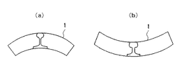
そのために、レール足裏部1bの冷却には限度があり、冷却面積の広いレール頭部1a側の方が、足裏部1bよりも冷却用空気の噴射量が多く、しかも、冷却される体積が大きいので、空気による強制冷却後、レール全体が図2(a) に示すような下曲がりになる傾向が強い。その結果、形状矯正のためのプレス工程が必要になり、生産能率を阻害する上、コスト高となる問題が生ずる。
【0007】
先行技術のような、レール1の頭部1aおよび足裏部1bを同時に冷却する方法では、レール足部の硬度を規定値(Hv:410)以下に抑え、しかも、冷却後にレールに曲がりが生じないようにすることは困難である。
【0008】
従って、この発明の目的は、上述した問題を解決し、レール頭部を微細なパーライト組織とし、その耐摩耗性および靱性を高めるために、熱間圧延された直後の高温のレール、または、熱間圧延後、熱処理のためにオーステナイト域温度以上に加熱された高温のレールを、冷却媒体により強制冷却するに際し、レールに曲がりの生ずることがなく、しかも、規定値を満足する硬度が得られる高温レールの冷却方法を提供することにある。
【0009】
この発明は、オーステナイト域温度以上に加熱された高温のレールをクランプで固定し、その足裏部のみを冷却媒体によって所定時間強制冷却した後、その頭部に対する冷却媒体による強制冷却を開始し、前記レールの頭部および足裏部の両方の冷却を、レール頭部の変態が終了するまで行い、かくして、前記レールに曲がりが生ずることなくレール頭部を微細なパーライト組織とし且つレール足部の硬度を規定値以下に抑えることに特徴を有するものである。
【0010】
【発明の実施の形態】
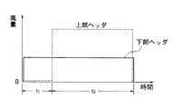
この発明においては、オーステナイト域の温度以上に加熱された高温のレールを、曲がり拘束用のクランプで固定し、図1に示すように、その足裏部1b側に設けられた下部ヘッダー3から噴射される空気や水などの冷却媒体によって、レール1の足裏部1bを図3に示す一定時間(t1)冷却する。
【0011】
次いで、レール足裏部1bと共に、レール頭部1a側に設けられた上部ヘッダー2によるレール頭部1aの矯正冷却を開始し、頭部1aおよび足裏部1bの両方の冷却を、図3に示すように、頭部の変態が終了するまでの時間(t2)行って、レール頭部1aの組織を微細なパーライト組織にする。そしてその後、レールの曲がり拘束用クランプを外す。
【0012】
この発明において、レール頭部の温度とレール足部の温度とがほぼ等しくなるように、レール頭部1aおよびレール足裏部1bの両方の冷却を行う前に、レール足裏部1bの冷却を一定時間(t1)行うことが重要である。レール足裏部1bを空気で強制冷却する場合の冷却時間(t1)は、15〜40秒位が適当であり、これによって、レールの曲がりを100mm以下に抑えることができる。
【0013】
レール頭部1aおよびレール足裏部1bの両方の冷却を行う前に、上述したレール足裏部1bの冷却を行わない場合には、冷却媒体による強制冷却終了時にレール頭部1aの温度が高くなり、その後自然放冷が進行するに従って、図2(b) に示すような上曲がりが発生する。
【0014】
【実施例】
〔実施例1〕
次に、この発明を実施例により説明する。900℃で熱間圧延を終了した長尺のレールを25mの長さに分割し、このように分割されたレール1を熱処理(SQ)装置に装入し、曲がりを拘束するためのクランプによってこれを固定した。
【0015】
次いで、レール頭部1aの温度が780℃の状態から、図1に示す下部ヘッダー3より噴射される冷却媒体としての空気により、図3に示す冷却時間(t1)を30秒に設定し、レール足裏部1bに対する冷却を開始した。
【0016】
次いで、レール頭部1a側に設けられた上部ヘッダー2によって、レール足裏部1bと共にレール頭部1aの冷却を開始し、頭部1aおよび足裏部1bの両方を、図3に示す冷却時間(t2)を150秒に設定して強制冷却した。次いで、上部ヘッダー2および下部ヘッダー3からの空気噴射を停止し、そして、レール1をクランプから外して熱処理(SQ)装置からレールを搬出した後、冷却床においてレール1を自然放冷した。
【0017】
このようにして冷却後の、25mレールの曲がりを測定した結果、曲がり(h)は30mmであった。また、レール足裏部の硬さ(Hv)は373で、規定値以下であり、得られたレールの曲がりは、10m当たりの曲がり規定値10mm、25m長さに換算すると62.5mmよりも小さく、その硬さ(Hv)は、規定値410以下を十分に満足していた。
【0018】
〔比較例1〕
実施例1と同様に分割されたレール1を熱処理(SQ)装置に装入し、曲がりを拘束するためのクランプによってこれを固定した。次いで、レール頭部1aおよびレール足裏部1bの両方を、図3に示す冷却時間(t2)を150秒に設定して強制冷却した後、実施例1と同様に熱処理(SQ)装置からレールを搬出し、冷却床においてレール1を自然放冷した。
【0019】
このような条件で冷却した後の、25mレールの曲がりを測定した結果、曲がり(h)は330mmであり、規定値62.5mmを超えて大きかった。なお、レール足裏部の硬さ(Hv)は375で、規定値410以下を満足していた。
【0020】
〔比較例2〕
比較例1と同様に、レール頭部1aおよびレール足裏部1bの両方を、図3に示す冷却時間(t2)を150秒に設定して強制冷却した。但し、このときのレール足裏部1bに対する冷却用空気の流量を、比較例1の3倍とした。
【0021】
このような条件で冷却した後の、25mレールの曲がりを測定した結果、曲がり(h)は60mmであり、規定値62.5mmより小さかった。しかし、レール足裏部の硬さ(Hv)は412となり、規定値410を超えていた。
【0022】
〔比較例3〕
比較例1と同様に、レール頭部1aおよびレール足裏部1bの両方を、図3に示す冷却時間(t2)を250秒に設定して強制冷却した。このときのレール頭部1aおよびレール足裏部1bに対する冷却用空気の流量は比較例1の場合と同様とした。
【0023】
このような条件で冷却した後の、25mレールの曲がりを測定した結果、曲がり(h)は40mmであり、規定値62.5mmより小さく、また、レール足裏部の硬さ(Hv)は376で、規定値410以下であった。しかしながら、熱処理(SQ)装置における処理時間が、実施例1の場合に比べて70秒多く必要になったため生産性が低下した。
【0024】
【発明の効果】
以上述べたように、この発明の方法によれば、レール頭部を微細なパーライト組織とするために、高温レールをクランプしその頭部を強制冷却するに先立って、レール足裏部のみを所定時間強制冷却することにより、クランプ拘束解除後のレールに生ずる曲がりは極めて小さく、また、その後の放冷過程における曲がりも殆ど発生せず、しかも、規定値を満足する硬度が得られ、形状矯正のためのプレス工程が不要になり、生産性も低下することがない等、多くの工業上有用な効果がもたらされる。
【図面の簡単な説明】
【図1】この発明の方法で使用されるレール冷却用ヘッダーの配置図である。
【図2】レールの下曲がりおよび上曲がり状態を示す説明図である。
【図3】レール冷却用空気流量の時間的変化を示す図である。
【符号の説明】
1 レール
1a レール頭部
1b レール足裏部
2 上部ヘッダー
3 下部ヘッダー
4 仕上圧延機[0001]
BACKGROUND OF THE INVENTION
This invention has a fine pearlite structure at the head of a high-temperature rail immediately after hot rolling or a high-temperature rail heated to austenite temperature or higher for heat treatment after hot rolling. Therefore, the present invention relates to a method for cooling a high-temperature rail that is forcibly cooled by a cooling medium such as air or water.
[0002]
[Prior art]
The rail head has a fine pearlite structure, and in order to increase its wear resistance and toughness, the high-temperature rail immediately after hot rolling, or a temperature above the austenite temperature for heat treatment after hot rolling In a heat treatment (SQ) apparatus, heat treatment (SQ) for forcibly cooling the head with a cooling medium such as air or water is performed on the high-temperature rail heated by the heat treatment (SQ) apparatus. Yes.
[0003]
From the viewpoint of the material of making the rail head a fine pearlite structure, it is only necessary to forcibly cool only the rail head. However, if only the rail head is forcibly cooled, the upper and lower sides of the rail are in an asymmetric temperature range. As a result, after the cooling is finished, when the rail clamp is removed, there is a problem that a large bending occurs in the rail due to the stress existing inside the rail.
[0004]
In order to prevent such a problem, for example, in Japanese Patent Laid-Open Nos. 61-60827 and 63-114923, an upper portion provided on the head 1a side of the rail 1 is shown in FIG. A method of forcibly cooling the head 1a and the sole 1b of the rail 1 simultaneously with a cooling medium sprayed from the header 2 and the lower header 3 provided on the sole 1b side of the rail 1 (hereinafter referred to as the prior art). Is disclosed.
[0005]
[Problems to be solved by the invention]
According to the prior art, the residual bending after cooling can be reduced as compared with the case where only the rail head is cooled. However, if the cooling of the rail foot sole 1b by the lower header 3 is too strong, the cooling speed of the rail foot increases and the hardness of the rail foot becomes higher than the specified value (Hv: 410).
[0006]
For this reason, there is a limit to the cooling of the rail foot 1b, and the rail head 1a side with a larger cooling area has a larger injection amount of cooling air than the foot 1b, and the volume to be cooled. Therefore, after forced cooling with air, the entire rail tends to bend downward as shown in Fig. 2 (a). As a result, a pressing process for shape correction is required, which hinders production efficiency and increases costs.
[0007]
In the method of simultaneously cooling the head 1a and the sole 1b of the rail 1 as in the prior art, the hardness of the rail foot is suppressed to a specified value (Hv: 410) or less, and the rail is bent after cooling. It is difficult to avoid.
[0008]
Accordingly, an object of the present invention is to solve the above-mentioned problems, to make the rail head a fine pearlite structure, and to improve its wear resistance and toughness, the high-temperature rail immediately after hot rolling, or heat After hot rolling, when a high-temperature rail heated above the austenite temperature for heat treatment is forcibly cooled by a cooling medium, the rail does not bend and a high temperature that provides a hardness satisfying the specified value is obtained. It is in providing the cooling method of a rail.
[0009]
This invention fixes a high-temperature rail heated to an austenite region temperature or higher with a clamp, and forcibly cools only the sole portion with a cooling medium for a predetermined time, and then starts forced cooling with a cooling medium on the head, The cooling of both the head and the foot of the rail is performed until the transformation of the rail head is completed, and thus the rail head has a fine pearlite structure and the rail foot without bending of the rail. It is characterized by keeping the hardness of the steel below a specified value .
[0010]
DETAILED DESCRIPTION OF THE INVENTION
In this invention, a high-temperature rail heated to a temperature higher than the temperature of the austenite region is fixed with a clamp for bending restraint, and as shown in FIG. 1, it is injected from the lower header 3 provided on the sole 1b side. The sole 1b of the rail 1 is cooled for a predetermined time (t 1 ) shown in FIG. 3 by a cooling medium such as air or water.
[0011]
Next, along with the rail sole 1b, the head head 1a provided on the rail head 1a side is started to correct and cool the rail head 1a, and both the head 1a and the sole 1b are cooled as shown in FIG. As shown, the time (t 2 ) until the transformation of the head is completed is performed to make the structure of the rail head 1a into a fine pearlite structure. After that, the rail bending restraint clamp is removed.
[0012]
In this invention, before cooling both the rail head 1a and the rail foot 1b, the rail foot 1b is cooled so that the rail head temperature and the rail foot temperature are substantially equal. It is important to carry out for a certain time (t 1 ). The cooling time (t 1 ) when the rail sole 1b is forcibly cooled with air is suitably about 15 to 40 seconds, and the bending of the rail can be suppressed to 100 mm or less.
[0013]
If the above-described rail foot 1b is not cooled before cooling both the rail head 1a and the rail sole 1b, the temperature of the rail head 1a is high at the end of forced cooling with the cooling medium. Then, as natural cooling proceeds, an upward bend as shown in FIG. 2 (b) occurs.
[0014]
【Example】
[Example 1]
Next, the present invention will be described with reference to examples. The long rail that has been hot-rolled at 900 ° C. is divided into 25 m lengths, and the rail 1 thus divided is loaded into a heat treatment (SQ) device, and this is clamped to restrain the bending. Fixed.
[0015]
Next, from the state where the temperature of the rail head portion 1a is 780 ° C., the cooling time (t 1 ) shown in FIG. 3 is set to 30 seconds by the air as the cooling medium injected from the lower header 3 shown in FIG. Cooling for the rail sole 1b was started.
[0016]
Next, cooling of the rail head 1a is started together with the rail foot 1b by the upper header 2 provided on the rail head 1a side, and both the head 1a and the foot 1b are cooled in the cooling time shown in FIG. (T 2 ) was set to 150 seconds and forced cooling was performed. Next, air injection from the upper header 2 and the lower header 3 was stopped, and after the rail 1 was removed from the clamp and the rail was unloaded from the heat treatment (SQ) apparatus, the rail 1 was naturally cooled in the cooling floor.
[0017]
As a result of measuring the bending of the 25 m rail after cooling in this way, the bending (h) was 30 mm. Moreover, the hardness (Hv) of the rail sole is 373, which is less than the specified value, and the bending of the obtained rail is less than 62.5 mm when converted to a specified bending value of 10 mm and 25 m per 10 m. The hardness (Hv) sufficiently satisfied the specified value of 410 or less.
[0018]
[Comparative Example 1]
The rail 1 divided in the same manner as in Example 1 was inserted into a heat treatment (SQ) apparatus, and this was fixed by a clamp for restraining bending. Next, both the rail head portion 1a and the rail foot portion 1b are forcibly cooled by setting the cooling time (t 2 ) shown in FIG. 3 to 150 seconds, and then from the heat treatment (SQ) apparatus as in the first embodiment. The rail was taken out and the rail 1 was naturally cooled in the cooling floor.
[0019]
As a result of measuring the bending of the 25 m rail after cooling under such conditions, the bending (h) was 330 mm, which was larger than the specified value of 62.5 mm. In addition, the hardness (Hv) of the rail foot part was 375, which satisfied the specified value 410 or less.
[0020]
[Comparative Example 2]
Similarly to Comparative Example 1, both the rail head portion 1a and the rail foot sole portion 1b were forcibly cooled by setting the cooling time (t 2 ) shown in FIG. 3 to 150 seconds. However, the flow rate of the cooling air with respect to the rail sole 1b at this time was three times that of Comparative Example 1.
[0021]
As a result of measuring the bending of the 25 m rail after cooling under such conditions, the bending (h) was 60 mm, which was smaller than the specified value of 62.5 mm. However, the hardness (Hv) of the rail sole was 412 and exceeded the specified value 410.
[0022]
[Comparative Example 3]
Similar to Comparative Example 1, both the rail head 1a and the rail sole 1b were forcibly cooled with the cooling time (t 2 ) shown in FIG. 3 set to 250 seconds. The flow rate of the cooling air to the rail head 1a and the rail sole 1b at this time was the same as that in Comparative Example 1.
[0023]
As a result of measuring the bending of the 25-m rail after cooling under such conditions, the bending (h) is 40 mm, which is smaller than the specified value 62.5 mm, and the hardness (Hv) of the rail sole is 376. The specified value was 410 or less. However, since the processing time in the heat treatment (SQ) apparatus is 70 seconds longer than that in the case of Example 1, productivity is lowered.
[0024]
【The invention's effect】
As described above, according to the method of the present invention, in order to make the rail head part a fine pearlite structure, prior to clamping the high temperature rail and forcibly cooling the head part, only the rail sole part is predetermined. By the forced cooling for a time, the bend generated in the rail after releasing the clamp restraint is extremely small, and the bend in the subsequent cooling process hardly occurs, and the hardness satisfying the specified value is obtained, and the shape correction Therefore, many industrially useful effects are brought about, such as no need for a pressing step and no reduction in productivity.
[Brief description of the drawings]
FIG. 1 is a layout view of a rail cooling header used in the method of the present invention.
FIG. 2 is an explanatory diagram showing a state where the rail is bent downward and upward.
FIG. 3 is a diagram showing temporal changes in rail cooling air flow rate.
[Explanation of symbols]
1 rail
1a Rail head
1b Rail sole 2 Upper header 3 Lower header 4 Finishing mill


