JP3807802B2 - Rib oil seal - Google Patents
Rib oil seal Download PDFInfo
- Publication number
- JP3807802B2 JP3807802B2 JP35230096A JP35230096A JP3807802B2 JP 3807802 B2 JP3807802 B2 JP 3807802B2 JP 35230096 A JP35230096 A JP 35230096A JP 35230096 A JP35230096 A JP 35230096A JP 3807802 B2 JP3807802 B2 JP 3807802B2
- Authority
- JP
- Japan
- Prior art keywords
- rib
- thickness
- seal lip
- seal
- oil
- Prior art date
- Legal status (The legal status is an assumption and is not a legal conclusion. Google has not performed a legal analysis and makes no representation as to the accuracy of the status listed.)
- Expired - Fee Related
Links
Images


Description
【0001】
【発明の属する技術分野】
この発明は、密封性を高めるための多数のリブを有するリブ付オイルシールに関する。
【0002】
【従来の技術】
オイルシールの密封作用の要因の一つとされるいわゆるポンピング作用は、シールの空気側へ漏洩しようとする油を、油を注入した側(油側)へ押し戻す作用である。このポンピング作用は、通常のプレーンシール(後述のリブを有しないシール)においても多少発揮することができる。しかし、このプレーンシールは、その使用に伴うシールリップの経時的な摩耗によって、上記ポンプ作用が極端に小さくなって、比較的早期に油漏れが生じるという問題があった。
【0003】
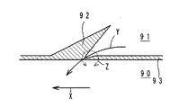
そこで、シールの空気側傾斜面に、稜線がシールリップの先端縁に対して傾斜する断面山形のリブを多数形成したリブ付オイルシール(ヘリックスシール)が提供されている(例えば実開昭62−128278号公報参照)。このリブ付オイルシールは、図8に示すように、油側90から空気側91に漏れた油を、軸の矢印X方向への回転に伴って、リブ92に沿わせて当該リブ92の近傍に生じる軸との接触圧が低い領域Zを通して、油側へ押し戻すものであり(同図矢印Y参照)、上記リブによってポンピング作用を高め、長期間に亘ってシールリップの摩耗を抑制することができる。
【0004】
【発明が解決しようとする課題】
しかし、上記リブ付オイルシールについても、長期間の使用によってポンピング作用が低下して、油漏れが生じるおそれがある。これは、図9に示すように、軸との摺接によってシールリップの先端縁93がほぼ平坦に摩耗して、軸との接触幅Wが大きくなり、当該先端縁93と軸との接触圧が全周に亘ってほぼ均等になること、つまり、図8に示す接触圧が低い領域Zが消失すること、及びリブの摩耗に伴って、リブと軸との軸方向の接触幅Dが大幅に小さくなることに起因する。
この発明は上記問題点に鑑みてなされたものであり、より長期間に亘って密封性を確保することができるリブ付オイルシールを提供することを目的とする。
【0005】
【課題を解決するための手段】
上記目的を達成するためのこの発明のリブ付オイルシールは、内周面に、互いに反対方向に傾斜した空気側傾斜面及び油側傾斜面を有する断面くさび状で使用中に軸と摺接する環状シールリップを備え、
上記空気側傾斜面に、稜線がシールリップの先端縁に対して傾斜する断面山形で使用中に軸と摺接するリブを多数突設しているリブ付オイルシールにおいて、
上記シールリップ及びリブの少なくとも軸との接触面に、この接触面の形状に倣う硬質の固体潤滑膜を形成し、
前記摺接に伴う上記シールリップの先端縁の磨耗を上記リブの磨耗より遅延させるべく、上記リブに形成した固体潤滑膜の厚みを、シールリップに形成した固体潤滑膜の厚みよりも数μmから数十μm薄くしたことを特徴とするものである。
【0006】
一般にリブ付オイルシールは、リブの稜線を挟んだ一対の傾斜面の軸に対する接触圧は、軸の回転方向に対して順方向に位置する傾斜面(以下「第1傾斜面」という)よりも、逆方向に位置する傾斜面(以下「第2傾斜面」という)の方が高くなる。このため、この発明のリブ付オイルシールにおいては、長期間に亘る軸との摺接によって、上記リブの第2傾斜面に形成した固体潤滑膜は、第1傾斜面に形成した固体潤滑膜よりも早く摩耗して、第2傾斜面にリップシールの素材であるゴムが露出する。すると、このゴムが露出した部分のうちの軸との接触圧が高い部分が摩耗して、当該部分の接触圧が低くなり、空気側に漏れた油を、上記接触圧が低くなった部分を通して油側に押し戻し易くなる。また、第1傾斜面の固体潤滑膜によって、リブの第1傾斜面の摩耗が抑制されるので、リブと軸との軸方向の接触幅D(図4参照)が小さくなるのを防止することができる。さらに、シールリップに形成した固体潤滑膜の厚みが、リブに形成した固体潤滑膜の厚みよりも厚いので、シールリップの先端縁の摩耗をリブの摩耗よりも遅延させることができる。このため、シールリップと軸との接触幅W(図4参照)が増大することに起因して、油を押し戻し易い接触圧が低い領域が消失するのを長期間に亘って抑制することができる。したがって、上記した従来のシールの密封性が低下する要因を全て解消することができる。
【0007】
上記固体潤滑膜としては、ポリテトラフルオロエチレンからなるのが好ましく、この場合のシールリップに形成した固体潤滑膜の厚みは、5〜45μmの範囲が、リブに形成した固体潤滑膜の厚みは、3〜43μmの範囲が、リブ付オイルシールの密封性をより長期間に亘って確保する上で好ましい。
また、上記固体潤滑膜が、ポリテトラフルオロエチレンからなる場合には、上記シールリップに形成した固体潤滑膜の厚みは、13〜17μmの範囲であるのが、リブに形成した固体潤滑膜の厚みは、10〜14μmの範囲であるのがさらに好ましい。これにより、リブ付オイルシールの密封性をより一層長期間に亘って確保することができる。さらにこの場合において、上記リブに形成した固体潤滑膜の厚みは、シールリップに形成した固体潤滑膜の厚みよりも2〜3μm薄くしているのが、リブ付オイルシールの密封性をより一層長期間に亘って確保する上で好ましい。
【0008】
【発明の実施の形態】
以下、この発明の実施の形態について、添付図面を参照しながら説明する。
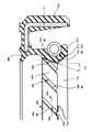
図1はこの発明のリブ付オイルシールの一つの実施の形態を示す要部断面図である。このリブ付オイルシールは、環状の芯金1に環状のゴム弾性体2が加硫接着されており、このゴム弾性体2の内周シール部2aの内周面に、環状のシールリップ3と環状のダストリップ4とが形成されている。
【0009】
シールリップ3は、軸の外周面に摺接して、軸との隙間を密封するものであり、互いに反対方向に傾斜した空気側傾斜面6と油側傾斜面7とを有する断面くさび状に形成されている。図においては左側が空気側に、右側が油側にそれぞれ設定されている。
シールリップ3の空気側傾斜面6には、シールリップ3のポンピング作用を増大させるためのリブ8が、所定間隔毎に多数形成されている。各リブ8は、断面が山形に形成されており(図2参照)、その稜線8aは、シールリップ3の先端縁3aに対して所定角度β(例えば45°)傾斜している。また、各リブ8は、それぞれ螺旋形状の一部を構成しており、その空気側傾斜面6からの突出高さHは、軸径52.4mm用のもので、例えば30〜40μmに設定されおり、頂角αは90°〜100°程度に設定されている。さらに、空気側傾斜面6の母線とオイルシールの軸芯とのなす角(バレル角)γは、20°程度に設定されている。なお、上記リブ8は、一方向だけでなく双方向に傾斜させて形成する場合もある。
【0010】
上記シールリップ3の空気側傾斜面6及び油側傾斜面7、並びにリブ8のそれぞれの表面には、固体潤滑剤としてのポリテトラフルオロエチレン(PTFE)からなる第1固体潤滑膜C1並びに第2固体潤滑膜C2がそれぞれ形成されている。各固体潤滑膜C1,C2は、上記PTFEを塗布した後、焼き付けることによって形成した硬質のものである。また、上記リブ8に形成された第2固体潤滑膜C2の厚みは、上記シールリップ3に形成された第1固体潤滑膜C1の厚みよりも数μmから数十μm薄くなっている。上記第1固体潤滑膜C1の厚みは、5〜45μmの範囲が、第2固体潤滑膜C2の厚みは、3〜43μmの範囲が好ましい。
【0011】
なお、上記実施の形態においては、リブ8の稜線8aを挟んだ一対の傾斜面のうち、図2の左側の傾斜面が、軸に対する接触圧が低い第1傾斜面8bとして構成されており、同図の右側の傾斜面が、軸に対する接触圧が第1傾斜面8bよりも高い第2傾斜面8cとして設定されている。
【0012】
以上の構成のリブ付オイルシールは、第1固体潤滑膜C1及び第2固体潤滑膜C2によって、シールリップ3の弾性が高められる。また、第2固体潤滑膜C2の厚みが、第1固体潤滑膜C1の厚みよりも薄いので、固体潤滑膜を形成していない従来品に比較して、リブ8の空気側傾斜面6からの突出高さHが低くなる。このため、シールリップ3のリブ8近傍の軸に対する接触圧が低い領域Z(図3参照)が狭くなる。さらに、リブ8の空気側傾斜面6からの突出高さHが低くなることに起因して、リブ8と軸との軸方向の接触幅Dが、従来品よりも小さくなる。以上により、上記実施の形態に示すリブ付オイルシールは、その使用初期において、軸の矢印X方向への回転に伴うポンピング作用が従来品よりも低下する。但しこのポンピング作用の低下は僅かであり、実用上全く問題なく密封性を確保することができる。
【0013】
次に、上記リブ付オイルシールを長期間使用すると、図4に示すように、軸との摺接時の面圧の差によって、上記リブ8の第2傾斜面8cに形成した第2固体潤滑膜C2は、第1傾斜面8bに形成した第2固体潤滑膜C2よりも早く摩耗する。このため、第2傾斜面8cにリップシール3の素材であるゴムが露出する。
そして、第2傾斜面8cの上記ゴムが露出した部分のうちの軸との接触圧が高い部分Vが摩耗して、当該部分Vの接触圧が低くなる。このため、空気側に漏れた油を、上記接触圧が低くなった部分を通して油側に押し戻し易くなる。
また、上記第2固体潤滑膜C2によって、リブ8の第1傾斜面8bの摩耗が抑制されるので、リブ8と軸との接触幅Dが小さくなるのを防止することができる。
さらに、第1固体潤滑膜C1の厚みが、第2固体潤滑膜C2の厚みよりも厚いので、シールリップ3の先端縁3aの摩耗をリブ8の摩耗よりも遅延させることができる。このため、シールリップ3と軸との接触幅Wが増大することに起因して、油を押し戻し易い接触圧が低い領域Zが消失するのを長期間に亘って抑制することができる。したがって、従来のシールの密封性が低下する要因を全て解消して、リブ付オイルシールの長寿命化を図ることができる。
なお。図3及び図4には、説明の便宜上、各固体潤滑膜C1,C2に対応する部分を斜線で示している。
【0014】
上記リブ付オイルシールにおいて、シールリップ3に形成された第1固体潤滑膜C1厚みは、13〜17μmの範囲が、リブ8に形成された第2固体潤滑膜C2の厚みは、10〜14μmの範囲がさらに好ましい。また、この場合において、第2固体潤滑膜C2の厚みは第1固体潤滑膜C1の厚みよりも2〜3μm薄くしているのが好ましい。これは、第2固体潤滑膜C2の厚みが第1固体潤滑膜C1の厚みに対して上記2〜3μmの範囲よりもさらに薄いと、第2傾斜面8cのゴムの露出時期が早すぎるからであり、反対に第2固体潤滑膜C2と第1固体潤滑膜C1の厚みの差が、上記2〜3μmの範囲よりも小さいと、ゴムが露出し難くなるからである。なお、上記第1固体潤滑膜C1の厚みの最適値は15μmであり、第2固体潤滑膜C2の厚みの最適値は12μmである。
【0015】
【実施例】
実施例として、図1に示す形状であって、シールリップの空気側傾斜面及び油側傾斜面並びにリブのそれぞれの表面に、PTFEを吹き付けた後、これを焼き付けて固体潤滑膜を有するリブ付オイルシールを作製した。このリブ付オイルシールの詳細は以下のとおりである。
▲1▼軸径52.4mm用
▲2▼シールリップに形成した固体潤滑膜の厚み:15μm
▲3▼リブに形成した固体潤滑膜の厚み:12μm
▲4▼リブの傾斜方向:一方向
▲5▼空気側傾斜面からのリブの突出高さ:40μm
▲6▼バレル角:20°
▲7▼トリム角:45°
【0016】
比較例として、上記固体潤滑膜を形成した点以外は実施例と同じリブ付オイルシールを準備し、実施例と比較例のそれぞれについて、運転時間とポンプ量との関係についての比較試験を行った。この試験条件は以下の通りである。
▲1▼油種:ATF DII
▲2▼試験温度:80°C
▲3▼軸偏芯:0.05mmTIR以下
▲4▼組付偏芯:0.15TIR
▲5▼軸回転数:9000rpm
ここで、上記TIRとは、総偏芯量を意味する。
この比較試験結果を図5に示す。図5より、比較例は経時的にポンプ量が低下するのに対して、実施例は使用初期においてポンプ量が比較例よりも若干低下するものの、200時間経過した時点でも、ポンプ量の低下は全く認められず、比較例よりも優れたポンピング作用を発揮することが分かる。
【0017】
上記実施例と比較例のそれぞれについて、運転時間と摩擦トルクとの関係についての比較試験を行った。この試験条件は上記比較試験と同じである。
この比較試験結果を図6に示す。図6より、実施例は比較例よりも摩擦トルクが低いことが分かる。
【0018】
上記実施例と比較例のそれぞれについて、シールリップと軸との接触幅の経時的な変化について比較試験を行った。この試験条件についても、上記比較試験と同じである。
この比較試験結果を図7に示す。図7より、実施例は比較例よりもシールリップと軸との接触幅の経時的な変化も少ないことが分かる。
以上の比較試験より、この発明のリブ付オイルシールは、ポンピング性能の向上、低トルク化、及び摩耗低減を図ることができることが明らかである。また、この発明のリブ付オイルシールは、使用初期の潤滑不足によるシールリップの振動、異音の発生、負圧によるリップ吸い付き等の諸問題も解決することができるとともに、低温使用時の耐摩耗の向上、低トルク化及び長寿命化も図ることができる。
【0019】
なお、固体潤滑膜としては、二硫化モリブデン等上記PTFE以外のもので構成することが可能である。また上記固体潤滑膜は、少なくとも軸との接触面に形成されていればよい。
【0020】
【発明の効果】
以上のように、この発明のリブ付オイルシールによれば、シールリップ及びリブの少なくとも軸との接触面に、この接触面の形状に倣う硬質の固体潤滑膜を形成し、軸との摺接に伴う上記シールリップの先端縁の磨耗を上記リブの磨耗より遅延させるべく、上記リブに形成した固体潤滑膜の厚みを、シールリップに形成した固体潤滑膜の厚みよりも数μmから数十μm薄くして、ポンピング作用の低下を長期間に亘って防止するようにしているので、オイルシールの寿命を大幅に延ばすことができるという特有の効果を奏する。
【図面の簡単な説明】
【図1】この発明のリブ付オイルシールの要部断面図である。
【図2】図1のII−II線拡大断面図である。
【図3】使用初期におけるシールリップ及びリブと軸との接触状態を示す図である。
【図4】所定期間使用した状態でのシールリップ及びリブと軸との接触状態を示す図である。
【図5】運転時間とポンプ量との関係を示すグラフ図である。
【図6】運転時間と摩擦トルクとの関係を示すグラフ図である。
【図7】シールリップと軸との接触幅の経時的な変化を示すグラフ図である。
【図8】従来例の使用初期におけるシールリップ及びリブと軸との接触状態を示す図である。
【図9】従来例の所定期間使用した状態でのシールリップ及びリブと軸との接触状態を示す図である。
【符号の説明】
3 シールリップ
3a シールリップの先端縁
6 空気側傾斜面
7 油側傾斜面
8 リブ
C1 第1固体潤滑膜
C2 第2固体潤滑膜[0001]
BACKGROUND OF THE INVENTION
The present invention relates to a ribbed oil seal having a large number of ribs for improving the sealing performance.
[0002]
[Prior art]
The so-called pumping action, which is one of the factors of the sealing action of the oil seal, is the action of pushing back the oil that is about to leak to the air side of the seal to the oil-injected side (oil side). This pumping action can be exerted somewhat even in a normal plain seal (a seal having no ribs described later). However, this plain seal has a problem that the pump action becomes extremely small due to wear of the seal lip with the use of the plain seal, and oil leakage occurs relatively early.
[0003]
Accordingly, an oil seal with a rib (helix seal) is provided in which a large number of ribs having a cross-sectional angle shape whose ridgeline is inclined with respect to the tip edge of the seal lip is formed on the air-side inclined surface of the seal (for example, Japanese Utility Model Laid-Open No. 62- 128278). As shown in FIG. 8, the oil seal with ribs is configured so that the oil leaked from the
[0004]
[Problems to be solved by the invention]
However, with the ribbed oil seal, the pumping action is reduced by long-term use, and oil leakage may occur. As shown in FIG. 9, the
This invention is made | formed in view of the said problem, and it aims at providing the oil seal with a rib which can ensure sealing performance over a longer period of time.
[0005]
[Means for Solving the Problems]
In order to achieve the above object, the ribbed oil seal of the present invention is a ring-shaped wedge having an air-side inclined surface and an oil-side inclined surface inclined in opposite directions on the inner peripheral surface, and is in sliding contact with the shaft during use. With a sealing lip,
In the oil seal with ribs, in which a large number of ribs slidably contact with the shaft during use are formed on the air-side inclined surface with ridges inclined to the tip edge of the seal lip,
A hard solid lubricating film that follows the shape of the contact surface is formed on the contact surface with at least the shaft of the seal lip and rib,
In order to delay the wear of the tip edge of the seal lip due to the sliding contact from the wear of the rib, the thickness of the solid lubricant film formed on the rib is from several μm than the thickness of the solid lubricant film formed on the seal lip. It is characterized by a thickness of several tens of μm.
[0006]
In general, an oil seal with a rib has a contact pressure with respect to an axis of a pair of inclined surfaces sandwiching a ridge line of the rib more than an inclined surface (hereinafter referred to as a “first inclined surface”) positioned in a forward direction with respect to the rotation direction of the shaft. The inclined surface located in the opposite direction (hereinafter referred to as “second inclined surface”) is higher. Therefore, in the oil seal with ribs of the present invention, the solid lubricating film formed on the second inclined surface of the rib by sliding contact with the shaft for a long period of time is more than the solid lubricating film formed on the first inclined surface. As a result, the rubber that is the material of the lip seal is exposed on the second inclined surface. Then, the part where the contact pressure with the shaft of the exposed part of the rubber is worn is worn, the contact pressure of the part decreases, and the oil leaked to the air side passes through the part where the contact pressure is reduced. It becomes easy to push back to the oil side. Further, since the wear of the first inclined surface of the rib is suppressed by the solid lubricating film of the first inclined surface, the axial contact width D (see FIG. 4) between the rib and the shaft is prevented from being reduced. Can do. Further, since the thickness of the solid lubricant film formed on the seal lip is thicker than the thickness of the solid lubricant film formed on the rib, the wear of the tip edge of the seal lip can be delayed more than the wear of the rib. For this reason, it can suppress over a long period that the area | region with a low contact pressure which is easy to push back oil lose | disappears because the contact width W (refer FIG. 4) of a seal lip and a shaft increases. . Therefore, it is possible to eliminate all the factors that cause the deterioration of the sealing performance of the conventional seal described above.
[0007]
The solid lubricant film is preferably made of polytetrafluoroethylene. In this case, the thickness of the solid lubricant film formed on the seal lip is in the range of 5 to 45 μm, and the thickness of the solid lubricant film formed on the rib is The range of 3 to 43 μm is preferable for ensuring the sealing performance of the oil seal with ribs over a longer period.
When the solid lubricant film is made of polytetrafluoroethylene, the thickness of the solid lubricant film formed on the seal lip is in the range of 13 to 17 μm. Is more preferably in the range of 10 to 14 μm. Thereby, the sealing performance of the oil seal with ribs can be ensured for a longer period of time. Furthermore, in this case, the thickness of the solid lubricating film formed on the rib is 2-3 μm thinner than the thickness of the solid lubricating film formed on the seal lip. It is preferable in securing over a period.
[0008]
DETAILED DESCRIPTION OF THE INVENTION
Embodiments of the present invention will be described below with reference to the accompanying drawings.
FIG. 1 is a cross-sectional view of an essential part showing an embodiment of an oil seal with ribs according to the present invention. In this oil seal with ribs, an annular rubber
[0009]
The
A large number of
[0010]
A first solid lubricating film C1 and a second solid lubricating film C1 made of polytetrafluoroethylene (PTFE) as a solid lubricant are respectively formed on the air-side
[0011]
In the above-described embodiment, of the pair of inclined surfaces sandwiching the ridge line 8a of the
[0012]
In the oil seal with ribs having the above configuration, the elasticity of the
[0013]
Next, when the oil seal with ribs is used for a long period of time, as shown in FIG. 4, the second solid lubrication formed on the second inclined surface 8c of the
And the part V with a high contact pressure with the axis | shaft of the part which the said rubber | gum exposed of the 2nd inclined surface 8c wears, and the contact pressure of the said part V becomes low. For this reason, it becomes easy to push back the oil leaked to the air side to the oil side through the part where the said contact pressure became low.
Further, since the wear of the first inclined surface 8b of the
Furthermore, since the thickness of the first solid lubricant film C1 is thicker than the thickness of the second solid lubricant film C2, the wear of the tip edge 3a of the
Note that. In FIG. 3 and FIG. 4, for convenience of explanation, portions corresponding to the respective solid lubricant films C1 and C2 are indicated by hatching.
[0014]
In the oil seal with ribs, the thickness of the first solid lubricating film C1 formed on the
[0015]
【Example】
As an example, the shape shown in FIG. 1, with PTFE sprayed on the air-side inclined surface and oil-side inclined surface of the seal lip and the respective surfaces of the rib, and then baked to provide a rib with a solid lubricating film An oil seal was made. The details of the oil seal with ribs are as follows.
(1) For shaft diameter of 52.4 mm (2) Thickness of solid lubricant film formed on seal lip: 15 μm
(3) Thickness of the solid lubricating film formed on the rib: 12 μm
(4) Rib inclination direction: One direction (5) Rib protrusion height from air side inclined surface: 40 μm
(6) Barrel angle: 20 °
(7) Trim angle: 45 °
[0016]
As a comparative example, the same oil seal with a rib as in the example except that the solid lubricating film was formed was prepared, and a comparative test was performed on the relationship between the operation time and the pump amount for each of the example and the comparative example. . The test conditions are as follows.
(1) Oil type: ATF DII
(2) Test temperature: 80 ° C
(3) Shaft eccentricity: 0.05 mm TIR or less (4) Assembly eccentricity: 0.15 TIR
(5) Shaft rotation speed: 9000rpm
Here, the TIR means the total eccentricity.
The results of this comparative test are shown in FIG. From FIG. 5, the pump amount in the comparative example decreases with time, whereas in the example, the pump amount is slightly lower than that in the comparative example in the initial use, but even when 200 hours have elapsed, the decrease in the pump amount does not occur. It can be seen that the pumping action superior to that of the comparative example is exhibited.
[0017]
About each of the said Example and a comparative example, the comparative test about the relationship between operation time and a friction torque was done. This test condition is the same as the above comparative test.
The results of this comparative test are shown in FIG. FIG. 6 shows that the friction torque is lower in the example than in the comparative example.
[0018]
For each of the above Examples and Comparative Examples, a comparative test was performed regarding changes over time in the contact width between the seal lip and the shaft. This test condition is also the same as the comparative test.
The results of this comparative test are shown in FIG. From FIG. 7, it can be seen that the example has less change with time in the contact width between the seal lip and the shaft than the comparative example.
From the above comparative tests, it is apparent that the ribbed oil seal of the present invention can improve pumping performance, reduce torque, and reduce wear. In addition, the oil seal with ribs of the present invention can solve various problems such as vibration of the seal lip due to insufficient lubrication at the beginning of use, generation of abnormal noise, lip sticking due to negative pressure, and resistance to use at low temperatures. The wear can be improved, the torque can be reduced, and the life can be extended.
[0019]
As the solid lubricant film can be configured with other than two vulcanization of molybdenum above PTFE. Moreover, the said solid lubricating film should just be formed in the contact surface with an axis | shaft at least.
[0020]
【The invention's effect】
As described above, according to the oil seal with ribs of the present invention, a hard solid lubricating film that conforms to the shape of the contact surface is formed on at least the contact surface of the seal lip and rib with the shaft, and is in sliding contact with the shaft. In order to delay the wear of the leading edge of the seal lip accompanying the wear of the rib, the thickness of the solid lubricant film formed on the rib is several μm to several tens of μm than the thickness of the solid lubricant film formed on the seal lip. Since the thickness is reduced to prevent the pumping action from deteriorating over a long period of time, the oil seal life can be extended significantly.
[Brief description of the drawings]
FIG. 1 is a cross-sectional view of a main part of an oil seal with ribs according to the present invention.
2 is an enlarged sectional view taken along line II-II in FIG.
FIG. 3 is a view showing a contact state between a seal lip and a rib and a shaft in an initial stage of use.
FIG. 4 is a diagram showing a contact state between a seal lip and a rib and a shaft in a state in which the shaft is used for a predetermined period.
FIG. 5 is a graph showing the relationship between operating time and pump amount.
FIG. 6 is a graph showing the relationship between operating time and friction torque.
FIG. 7 is a graph showing a change with time of the contact width between the seal lip and the shaft.
FIG. 8 is a view showing a contact state between a seal lip and a rib and a shaft in an initial stage of use of a conventional example.
FIG. 9 is a view showing a contact state between a seal lip and a rib and a shaft in a state where the conventional example is used for a predetermined period.
[Explanation of symbols]
3 Seal lip
Claims (4)
上記空気側傾斜面に、稜線がシールリップの先端縁に対して傾斜する断面山形で使用中に軸と摺接するリブを多数突設しているリブ付オイルシールにおいて、
上記シールリップ及びリブの少なくとも軸との接触面に、この接触面の形状に倣う硬質の固体潤滑膜を形成し、
前記摺接に伴う上記シールリップの先端縁の磨耗を上記リブの磨耗より遅延させるべく、上記リブに形成した固体潤滑膜の厚みを、シールリップに形成した固体潤滑膜の厚みよりも数μmから数十μm薄くしたことを特徴とするリブ付オイルシール。Provided on the inner peripheral surface with an annular seal lip that slides in contact with the shaft during use in a wedge-shaped cross section having an air-side inclined surface and an oil-side inclined surface inclined in opposite directions,
In the oil seal with ribs, in which a large number of ribs slidably contact with the shaft during use are formed on the air-side inclined surface with ridges inclined to the tip edge of the seal lip,
A hard solid lubricating film that follows the shape of the contact surface is formed on the contact surface with at least the shaft of the seal lip and rib,
In order to delay the wear of the tip edge of the seal lip due to the sliding contact from the wear of the rib, the thickness of the solid lubricant film formed on the rib is from several μm than the thickness of the solid lubricant film formed on the seal lip. An oil seal with ribs, characterized by being thinned by several tens of μm.
Priority Applications (1)
| Application Number | Priority Date | Filing Date | Title |
|---|---|---|---|
| JP35230096A JP3807802B2 (en) | 1996-12-11 | 1996-12-11 | Rib oil seal |
Applications Claiming Priority (1)
| Application Number | Priority Date | Filing Date | Title |
|---|---|---|---|
| JP35230096A JP3807802B2 (en) | 1996-12-11 | 1996-12-11 | Rib oil seal |
Publications (2)
| Publication Number | Publication Date |
|---|---|
| JPH10169786A JPH10169786A (en) | 1998-06-26 |
| JP3807802B2 true JP3807802B2 (en) | 2006-08-09 |
Family
ID=18423125
Family Applications (1)
| Application Number | Title | Priority Date | Filing Date |
|---|---|---|---|
| JP35230096A Expired - Fee Related JP3807802B2 (en) | 1996-12-11 | 1996-12-11 | Rib oil seal |
Country Status (1)
| Country | Link |
|---|---|
| JP (1) | JP3807802B2 (en) |
Cited By (1)
| Publication number | Priority date | Publication date | Assignee | Title |
|---|---|---|---|---|
| KR101945381B1 (en) | 2017-08-30 | 2019-02-07 | (주)유니폴리 | Cartridge Oil Seal Using Transaxle |
Families Citing this family (6)
| Publication number | Priority date | Publication date | Assignee | Title |
|---|---|---|---|---|
| JP4167326B2 (en) * | 1998-07-23 | 2008-10-15 | 本田技研工業株式会社 | Aluminum alloy automatic transmission spool valve |
| IT1303577B1 (en) * | 1998-12-11 | 2000-11-14 | Skf Ind Spa | SEALING DEVICE FOR BEARINGS. |
| IT1311310B1 (en) * | 1999-12-10 | 2002-03-12 | Rft Spa | LOW FRICTION SEALING COMPLEX, IN PARTICULAR FOR ROLLING BEARINGS, AND PROCEDURE FOR ITS OBTAINING. |
| JP2009074602A (en) * | 2007-09-20 | 2009-04-09 | Nok Corp | Oil seal |
| EP2290269B1 (en) * | 2009-08-26 | 2016-07-06 | Carl Freudenberg KG | Seal |
| KR200497911Y1 (en) * | 2021-04-29 | 2024-04-03 | 푸이 오일 씰 인더스트리얼 코., 엘티디. | Oil seal structure |
-
1996
- 1996-12-11 JP JP35230096A patent/JP3807802B2/en not_active Expired - Fee Related
Cited By (1)
| Publication number | Priority date | Publication date | Assignee | Title |
|---|---|---|---|---|
| KR101945381B1 (en) | 2017-08-30 | 2019-02-07 | (주)유니폴리 | Cartridge Oil Seal Using Transaxle |
Also Published As
| Publication number | Publication date |
|---|---|
| JPH10169786A (en) | 1998-06-26 |
Similar Documents
| Publication | Publication Date | Title |
|---|---|---|
| US5083802A (en) | Lip seal device | |
| US4834397A (en) | Lip seal device having an annular groove | |
| US6860486B2 (en) | Shaft sealing ring | |
| JP3278349B2 (en) | Sealing device | |
| US3534969A (en) | Seal | |
| JPH0792151B2 (en) | Rotary shaft lip seal | |
| US20070182104A1 (en) | Sealing device | |
| JP3807802B2 (en) | Rib oil seal | |
| US5676383A (en) | Hydrodynamic low-torque lubricant seal with pumping projections | |
| US6276691B1 (en) | Oil seal | |
| JP3180285B2 (en) | Oil seal | |
| JP4380111B2 (en) | Sealing device | |
| US3807743A (en) | Fluid seal having pumping elements and cooperating auxiliary lip | |
| JP2673377B2 (en) | Sealing device for rotation | |
| JPH0627879Y2 (en) | Packing for rotating shaft | |
| JPH10196664A (en) | Sealing device for rolling bearing | |
| JP3166062B2 (en) | Lip type seal | |
| JPH0579859B2 (en) | ||
| JP2597961Y2 (en) | Sealing device | |
| JPH08226547A (en) | Oil seal | |
| JPH026303Y2 (en) | ||
| JPH11351406A (en) | Sealing device | |
| JP3560111B2 (en) | Sealing device | |
| JPH07269518A (en) | Lip packing for spline shaft | |
| JPH07217746A (en) | Oil seal and manufacturing thereof |
Legal Events
| Date | Code | Title | Description |
|---|---|---|---|
| A977 | Report on retrieval |
Free format text: JAPANESE INTERMEDIATE CODE: A971007 Effective date: 20041101 |
|
| A131 | Notification of reasons for refusal |
Free format text: JAPANESE INTERMEDIATE CODE: A131 Effective date: 20041116 |
|
| A521 | Written amendment |
Free format text: JAPANESE INTERMEDIATE CODE: A523 Effective date: 20050114 |
|
| A131 | Notification of reasons for refusal |
Free format text: JAPANESE INTERMEDIATE CODE: A131 Effective date: 20050802 |
|
| A521 | Written amendment |
Free format text: JAPANESE INTERMEDIATE CODE: A523 Effective date: 20051003 |
|
| TRDD | Decision of grant or rejection written | ||
| A01 | Written decision to grant a patent or to grant a registration (utility model) |
Free format text: JAPANESE INTERMEDIATE CODE: A01 Effective date: 20060418 |
|
| A61 | First payment of annual fees (during grant procedure) |
Free format text: JAPANESE INTERMEDIATE CODE: A61 Effective date: 20060516 |
|
| R150 | Certificate of patent or registration of utility model |
Free format text: JAPANESE INTERMEDIATE CODE: R150 |
|
| FPAY | Renewal fee payment (event date is renewal date of database) |
Free format text: PAYMENT UNTIL: 20100526 Year of fee payment: 4 |
|
| FPAY | Renewal fee payment (event date is renewal date of database) |
Free format text: PAYMENT UNTIL: 20110526 Year of fee payment: 5 |
|
| FPAY | Renewal fee payment (event date is renewal date of database) |
Free format text: PAYMENT UNTIL: 20110526 Year of fee payment: 5 |
|
| FPAY | Renewal fee payment (event date is renewal date of database) |
Free format text: PAYMENT UNTIL: 20120526 Year of fee payment: 6 |
|
| FPAY | Renewal fee payment (event date is renewal date of database) |
Free format text: PAYMENT UNTIL: 20120526 Year of fee payment: 6 |
|
| FPAY | Renewal fee payment (event date is renewal date of database) |
Free format text: PAYMENT UNTIL: 20130526 Year of fee payment: 7 |
|
| FPAY | Renewal fee payment (event date is renewal date of database) |
Free format text: PAYMENT UNTIL: 20140526 Year of fee payment: 8 |
|
| LAPS | Cancellation because of no payment of annual fees |