JP3807668B2 - Hydrogen supply device for fuel cell - Google Patents
Hydrogen supply device for fuel cell Download PDFInfo
- Publication number
- JP3807668B2 JP3807668B2 JP2001325756A JP2001325756A JP3807668B2 JP 3807668 B2 JP3807668 B2 JP 3807668B2 JP 2001325756 A JP2001325756 A JP 2001325756A JP 2001325756 A JP2001325756 A JP 2001325756A JP 3807668 B2 JP3807668 B2 JP 3807668B2
- Authority
- JP
- Japan
- Prior art keywords
- hydrogen
- fuel cell
- concentration
- supplied
- flow path
- Prior art date
- Legal status (The legal status is an assumption and is not a legal conclusion. Google has not performed a legal analysis and makes no representation as to the accuracy of the status listed.)
- Expired - Fee Related
Links
- 239000001257 hydrogen Substances 0.000 title claims description 391
- 229910052739 hydrogen Inorganic materials 0.000 title claims description 391
- UFHFLCQGNIYNRP-UHFFFAOYSA-N Hydrogen Chemical compound [H][H] UFHFLCQGNIYNRP-UHFFFAOYSA-N 0.000 title claims description 361
- 239000000446 fuel Substances 0.000 title claims description 187
- 239000012528 membrane Substances 0.000 claims description 61
- 150000002431 hydrogen Chemical class 0.000 claims description 29
- 238000000926 separation method Methods 0.000 description 41
- 239000012535 impurity Substances 0.000 description 30
- 238000001514 detection method Methods 0.000 description 26
- 238000000034 method Methods 0.000 description 26
- 239000007789 gas Substances 0.000 description 20
- 238000011049 filling Methods 0.000 description 18
- OKKJLVBELUTLKV-UHFFFAOYSA-N Methanol Chemical compound OC OKKJLVBELUTLKV-UHFFFAOYSA-N 0.000 description 9
- 238000010586 diagram Methods 0.000 description 9
- 230000007423 decrease Effects 0.000 description 8
- 239000007788 liquid Substances 0.000 description 6
- UGFAIRIUMAVXCW-UHFFFAOYSA-N Carbon monoxide Chemical compound [O+]#[C-] UGFAIRIUMAVXCW-UHFFFAOYSA-N 0.000 description 5
- 229910002091 carbon monoxide Inorganic materials 0.000 description 5
- 238000004817 gas chromatography Methods 0.000 description 4
- VNWKTOKETHGBQD-UHFFFAOYSA-N methane Chemical compound C VNWKTOKETHGBQD-UHFFFAOYSA-N 0.000 description 4
- 230000003247 decreasing effect Effects 0.000 description 3
- 229910052763 palladium Inorganic materials 0.000 description 3
- 239000012466 permeate Substances 0.000 description 3
- 238000000746 purification Methods 0.000 description 3
- 238000002407 reforming Methods 0.000 description 3
- 239000000956 alloy Substances 0.000 description 2
- 229910045601 alloy Inorganic materials 0.000 description 2
- 238000006243 chemical reaction Methods 0.000 description 2
- 239000002131 composite material Substances 0.000 description 2
- 239000004020 conductor Substances 0.000 description 2
- 230000000694 effects Effects 0.000 description 2
- 239000003502 gasoline Substances 0.000 description 2
- 150000004678 hydrides Chemical class 0.000 description 2
- 125000004435 hydrogen atom Chemical group [H]* 0.000 description 2
- 238000004519 manufacturing process Methods 0.000 description 2
- 239000000463 material Substances 0.000 description 2
- 239000003345 natural gas Substances 0.000 description 2
- 239000005518 polymer electrolyte Substances 0.000 description 2
- 238000010248 power generation Methods 0.000 description 2
- 239000007787 solid Substances 0.000 description 2
- 239000004215 Carbon black (E152) Substances 0.000 description 1
- 239000004642 Polyimide Substances 0.000 description 1
- 230000002159 abnormal effect Effects 0.000 description 1
- 230000005856 abnormality Effects 0.000 description 1
- 238000010521 absorption reaction Methods 0.000 description 1
- QVGXLLKOCUKJST-UHFFFAOYSA-N atomic oxygen Chemical compound [O] QVGXLLKOCUKJST-UHFFFAOYSA-N 0.000 description 1
- 239000006227 byproduct Substances 0.000 description 1
- 239000003054 catalyst Substances 0.000 description 1
- 238000007084 catalytic combustion reaction Methods 0.000 description 1
- 239000000919 ceramic Substances 0.000 description 1
- 239000011248 coating agent Substances 0.000 description 1
- 238000000576 coating method Methods 0.000 description 1
- 230000006835 compression Effects 0.000 description 1
- 238000007906 compression Methods 0.000 description 1
- 238000011109 contamination Methods 0.000 description 1
- 150000004696 coordination complex Chemical class 0.000 description 1
- 229910052802 copper Inorganic materials 0.000 description 1
- 238000013461 design Methods 0.000 description 1
- 230000006866 deterioration Effects 0.000 description 1
- 239000004205 dimethyl polysiloxane Substances 0.000 description 1
- 238000007599 discharging Methods 0.000 description 1
- 239000000428 dust Substances 0.000 description 1
- 238000005516 engineering process Methods 0.000 description 1
- 238000007429 general method Methods 0.000 description 1
- 238000010438 heat treatment Methods 0.000 description 1
- 239000012510 hollow fiber Substances 0.000 description 1
- 229930195733 hydrocarbon Natural products 0.000 description 1
- 150000002430 hydrocarbons Chemical class 0.000 description 1
- 230000001050 lubricating effect Effects 0.000 description 1
- 239000010687 lubricating oil Substances 0.000 description 1
- 238000012423 maintenance Methods 0.000 description 1
- 230000007257 malfunction Effects 0.000 description 1
- 238000005259 measurement Methods 0.000 description 1
- 229910052751 metal Inorganic materials 0.000 description 1
- 239000002184 metal Substances 0.000 description 1
- 238000002156 mixing Methods 0.000 description 1
- 238000012986 modification Methods 0.000 description 1
- 230000004048 modification Effects 0.000 description 1
- 229910052758 niobium Inorganic materials 0.000 description 1
- 239000003921 oil Substances 0.000 description 1
- 238000011017 operating method Methods 0.000 description 1
- 239000001301 oxygen Substances 0.000 description 1
- 229910052760 oxygen Inorganic materials 0.000 description 1
- 229920000435 poly(dimethylsiloxane) Polymers 0.000 description 1
- 229920002492 poly(sulfone) Polymers 0.000 description 1
- -1 polydimethylsiloxane Polymers 0.000 description 1
- 229920001721 polyimide Polymers 0.000 description 1
- 229920000642 polymer Polymers 0.000 description 1
- 229920006254 polymer film Polymers 0.000 description 1
- 229920005597 polymer membrane Polymers 0.000 description 1
- 230000001737 promoting effect Effects 0.000 description 1
- 229920002379 silicone rubber Polymers 0.000 description 1
- 239000004945 silicone rubber Substances 0.000 description 1
- 229910052709 silver Inorganic materials 0.000 description 1
- 238000001179 sorption measurement Methods 0.000 description 1
- 238000000629 steam reforming Methods 0.000 description 1
- 239000011232 storage material Substances 0.000 description 1
- 239000000126 substance Substances 0.000 description 1
- 239000000758 substrate Substances 0.000 description 1
- 238000011144 upstream manufacturing Methods 0.000 description 1
- 229910052720 vanadium Inorganic materials 0.000 description 1
- 230000008016 vaporization Effects 0.000 description 1
- XLYOFNOQVPJJNP-UHFFFAOYSA-N water Substances O XLYOFNOQVPJJNP-UHFFFAOYSA-N 0.000 description 1
Images


Classifications
-
- H—ELECTRICITY
- H01—ELECTRIC ELEMENTS
- H01M—PROCESSES OR MEANS, e.g. BATTERIES, FOR THE DIRECT CONVERSION OF CHEMICAL ENERGY INTO ELECTRICAL ENERGY
- H01M8/00—Fuel cells; Manufacture thereof
- H01M8/06—Combination of fuel cells with means for production of reactants or for treatment of residues
- H01M8/0662—Treatment of gaseous reactants or gaseous residues, e.g. cleaning
-
- H—ELECTRICITY
- H01—ELECTRIC ELEMENTS
- H01M—PROCESSES OR MEANS, e.g. BATTERIES, FOR THE DIRECT CONVERSION OF CHEMICAL ENERGY INTO ELECTRICAL ENERGY
- H01M8/00—Fuel cells; Manufacture thereof
- H01M8/04—Auxiliary arrangements, e.g. for control of pressure or for circulation of fluids
- H01M8/04082—Arrangements for control of reactant parameters, e.g. pressure or concentration
- H01M8/04089—Arrangements for control of reactant parameters, e.g. pressure or concentration of gaseous reactants
-
- Y—GENERAL TAGGING OF NEW TECHNOLOGICAL DEVELOPMENTS; GENERAL TAGGING OF CROSS-SECTIONAL TECHNOLOGIES SPANNING OVER SEVERAL SECTIONS OF THE IPC; TECHNICAL SUBJECTS COVERED BY FORMER USPC CROSS-REFERENCE ART COLLECTIONS [XRACs] AND DIGESTS
- Y02—TECHNOLOGIES OR APPLICATIONS FOR MITIGATION OR ADAPTATION AGAINST CLIMATE CHANGE
- Y02E—REDUCTION OF GREENHOUSE GAS [GHG] EMISSIONS, RELATED TO ENERGY GENERATION, TRANSMISSION OR DISTRIBUTION
- Y02E60/00—Enabling technologies; Technologies with a potential or indirect contribution to GHG emissions mitigation
- Y02E60/30—Hydrogen technology
- Y02E60/50—Fuel cells
Description
【0001】
【発明の属する技術分野】
本発明は、燃料電池車両に搭載された燃料電池用の水素供給装置に関し、さらに詳しくは、燃料電池に供給される水素が所定品位(所定濃度)以下にならないように水素を透過させる水素分離器を備えた燃料電池用の水素供給装置に関する。
【0002】
【従来の技術】
近年、電気自動車の動力源などとして固体高分子型の燃料電池が注目されている。固体高分子型の燃料電池(PEFC)は、常温でも発電することが可能であり、様々な用途に実用化されつつある。
【0003】
一般に、燃料電池システムは固体高分子電解質膜を挟んで一方側にカソード極を区画し、他方側にアノード極を区画して構成されており、カソード極に供給される空気中の酸素と、アノード極に供給される水素との化学反応によって発生した電力で外部負荷を駆動するシステムである。
【0004】
このような燃料電池の燃料となる水素供給源を確保する一般的な方法としては、
(1)純水素式;液体水素、あるいは高圧水素等の純水素を用いて液体水素タンク、高圧タンク、あるいは水素吸蔵合金などの水素貯蔵材に水素補給を行って供給源とする方法、
(2)改質式;炭化水素、例えばメタノール水溶液を用い水蒸気改質により水素を生成し供給源とする方法、
等が挙げられる。
【0005】
一方、車両に搭載された水素貯蔵容器等へ高圧水素を供給する高圧水素供給型の水素充填所における水素の供給方法としては、
(1)コンビナートなどで水素を製造し、製造した水素を液化した後、液化した水素を水素充填所へ輸送し、水素充填所にて液体水素を気化・昇圧して供給する方法、
(2)天然ガス等の有機ガス、メタノール、あるいはガソリンなどの有機液体燃料をリフォーマー(改質器)を用いてオンサイトで改質し、改質ガスを昇圧して供給する方法、
(3)有機系、あるいは金属錯体系ケミカルハイドライドなどからオンサイトで水素を取り出し、取り出した水素を昇圧して供給する方法、
等がある。
【0006】
【発明が解決しようとする課題】
しかしながら、高圧水素を供給するこれらの水素の供給方法は、以下の理由などから水素中へ不純物が混入してしまう場合がある。すなわち、
(1)天然ガス等の有機ガス、メタノール、あるいはガソリンなどの有機液体燃料をリフォーマー(改質器)を用いてオンサイトで改質したときに、燃料改質工程で一酸化炭素ガスが生成しこのガスが不純物として混入する。
(2)水素を昇圧するための圧縮工程で水素圧縮機の潤滑に使用される潤滑油等の油分が不純物として混入する。
(3)水素補給用ホースから極微量の水分・ゴミなどが不純物として混入する。
(4)また、水素製造プロセスのリフォーマー(改質器)の改質触媒の不調などにより水素以外の副産物を生成し、これらが不純物として水素中へ混入する。
(5)また、これらの不純物が蓄積して供給水素の品位(水素濃度)を燃料電池の許容水素品位(許容水素濃度)より低くしてしまう場合も想定される。
【0007】
これら不純物含有量の多い低品位水素(低純度水素)を使用すると、燃料電池が深刻な性能低下を生じる。
例えば燃料電池において水素燃料中に不純物が混入して不純物により電極での化学反応が抑制されると、燃料電池の発電電圧の低下、すなわち燃料電池の出力低下を生じる。そのため車両搭載用を初めとする水素貯蔵・供給装置を有する燃料電池(オンボード型燃料電池)においては、水素充填施設(オンサイト)から供給される水素中の不純物の混入に対しては利用装置側(オンボード)で対策を施し、燃料電池へ不純物が供給されるのを抑制する必要がある。
【0008】
低品位水素から水素のみを分離する水素分離器としては、図8に示すような膜分離装置102が知られている。不純物(例えば一酸化炭素ガス)を含む水素をこの膜分離装置102に供給すると、供給された不純物含有水素のうち水素は分離膜を通り不純物(一酸化炭素ガス)は分離膜を通過できないため、膜分離装置102を通過した水素中の不純物量は減少し、水素の品位(水素の純度)が向上する。一方、膜分離装置102内では分離膜を通過できなかった不純物(一酸化炭素ガス)の濃度が上昇し、低品位水素側(分離膜の上流側)の圧力が一定の場合、不純物成分の分圧が上昇、水素の分圧が減少し、分離膜での純化速度が低下してしまうため、不純物含有ガス(ブリードガス)の除去・放出が必要となる。このため低品位水素側の水素も一緒に捨てられている。
【0009】
本発明は、前記課題を解決するためになされたものであって燃料電池に供給する水素が常に所定品位(所定濃度)以上となるように供給でき、しかも燃料電池へ供給する水素の利用効率を向上させることができる燃料電池用の水素供給装置を提供することを目的とする。
【0010】
【課題を解決するための手段】
前記課題を解決するためになされた請求項1に記載された燃料電池用の水素供給装置は、燃料電池車両に搭載された水素貯蔵容器と、該水素貯蔵容器から燃料電池に水素を供給可能にする水素供給流路とを備えた燃料電池用の水素供給装置において、前記水素供給流路と並列して水素を前記燃料電池へ供給するバイパス流路と、前記バイパス流路に備えられ、かつ、水素透過膜を含み、該水素透過膜を透過した水素を前記燃料電池へ供給し、透過しなかった水素を排出する水素分離器と、前記水素供給流路と前記バイパス流路とを選択的に切り替える切替手段と、前記燃料電池へ供給される水素の濃度を検知する水素濃度検知手段と、を備え、前記燃料電池へ供給される水素中の水素濃度が所定濃度よりも低いと判定したときは、前記バイパス流路を介して前記燃料電池へ水素を供給するように前記切替手段を切り替えることを特徴とするものである。
【0011】
請求項1に記載の発明によると、燃料電池車両に搭載された水素貯蔵容器と、該水素貯蔵容器から燃料電池に水素を供給可能にする水素供給流路とを備えた燃料電池用の水素供給装置において、前記水素供給流路と並列して水素を前記燃料電池へ供給するバイパス流路と、水素透過膜を含み、該水素透過膜を透過した水素を前記燃料電池へ供給し、透過しなかった水素を排出する水素分離器を前記バイパス流路に備え、前記水素供給流路と前記バイパス流路とを選択的に切り替える切替手段を備えたことにより、必要に応じて前記水素供給流路と前記水素分離器を備えた前記バイパス流路とを選択的に切り替えることができる。
その結果、常時水素分離器を運転しなくてもよくなるので水素貯蔵容器から燃料電池へ供給する水素の利用効率が向上する。
【0013】
また、燃料電池へ供給する水素の濃度を検知する水素濃度検知手段を備え、水素中の水素濃度が所定濃度よりも低いと判定したときは、バイパス流路を介して前記燃料電池へ水素を供給するように切替手段を切り替えることにより、燃料電池の要求する高品位(高純度)の水素を燃料電池に供給することができる。
【0014】
請求項2に係る燃料電池用の水素供給装置は、前記水素濃度検知手段は、前記燃料電池の発電電流に対する起電力を検知し、前記起電力が通常の場合と比較して低い場合は、前記燃料電池へ供給される水素中の水素濃度が所定濃度よりも低いと判定することを特徴とする請求項1に記載の燃料電池用の水素供給装置である。
【0015】
請求項2に記載の発明によると、水素濃度検知手段として燃料電池の発電電流に対する起電力を検知し、前記起電力が通常の場合と比較して低い場合は、水素中の水素濃度が所定濃度よりも低いと判定することにより、水素供給流路やバイパス流路に備えた水素分離器の後流側から系内に不純物の混入があっても確実に不純物の混入の有無を判断することができる。従って、燃料電池の要求する高品位(高純度)の水素を確実に燃料電池に供給することができる。
【0016】
【発明の実施の形態】
本発明に係る燃料電池用の水素供給装置の実施の形態について図1から図7を参照して説明する。
最初に本発明に係る水素分離器について説明する。
一般に、水素中の不純物を分離・除去する方法には、膜分離法、PSA(圧力変動吸着法)、深冷分離法、溶液吸収法等がある。
このうち膜分離法は、機械的稼動部品が少なく、かつ装置構成も比較的簡単なため、本実施形態では水素分離器として、図1に示すような膜分離装置3を採用している。
【0017】
膜分離装置3は、上述したように低品位水素側の圧力が一定の場合、不純物成分の分圧が上昇し、水素の分圧が減少するので、分離膜での純化速度が低下してしまうので、ブリードガス(不純物含有ガス)を除去・放出するが、放出時に水素も一緒に放出するために膜分離装置3を作動すると燃費低下を招いてしまう。
従って、膜分離装置3は常時運転するのではなく、図1に示すような水素貯蔵容器2中の水素(これから燃料電池へ供給しようとする水素)の品位が燃料電池4にとり有害であるときのみ作動させる。
【0018】
次に、この膜分離装置3で使用される分離膜の材質について説明する。膜分離装置3で水素分離、純化に用いられる分離膜である水素透過膜としては、ポリイミド膜、ポリジメチルシロキサン膜等の高分子膜、Pd、Pd/Ag、Pd/Ag/Cu、V、Nb、非晶質水素吸蔵合金(AB2型、AB5型)等の金属膜、およびこれら分子膜と多孔質膜(多孔質高分子膜あるいは多孔膜セラミック膜)との複合膜等がある。
【0019】
上記Pd系等の金属膜は、低温時に高圧水素を供給した場合には、延性に乏しいβ相(水素化物相)を形成するので、この水素化物相の形成を抑制するために高温(例えば300℃)で作動させる方が好ましい。そこで、例えば膜分離装置3から排出されるブリードガス(不純物ガス)中に放出される水素を燃焼(触媒燃焼)して加熱源とすることで膜分離装置3の運転効率を向上させることが可能となる。
本実施形態では、膜分離装置3の水素透過膜として、基質にポリスルホン、コーティング材にシリコーンゴムを用いた中空糸複合膜を用いている。
【0020】
以下、車両に搭載される本発明に係る燃料電池用の水素供給装置の実施形態について説明する。
最初に、本発明に係る第一実施形態の燃料電池用の水素供給装置について図1及び図2を参照して説明する。尚、図1は本発明に係る第一実施形態の燃料電池用の水素供給装置の全体の構成を示す図、図2は本発明に係る第一実施形態の燃料電池用の水素供給装置の運転方法を説明するためのフローチャートである。
第一実施形態の燃料電池用の水素供給装置1は、図1に示すように、
水素充填口5を介して高圧の水素が供給・貯蔵される水素貯蔵容器2と、
その水素貯蔵容器2内(これから燃料電池4へ供給しようとする水素)の水素濃度を検知する水素濃度検知手段と、
この水素貯蔵容器2から燃料電池4に水素を供給可能にする水素供給流路HPと、
前記水素供給流路HPに設けられ、燃料電池4へ供給する水素の圧力を調整する2つのレギュレータRG1,RG2と、
前記水素供給流路HPと並列して水素を前記燃料電池4へ供給するバイパス流路BPと、
前記バイパス流路BPに設けられ、水素透過膜を含み、該水素透過膜を透過した水素を前記燃料電池4へ供給し、透過しなかった水素を排出する水素分離器である膜分離装置3と、
前記膜分離装置3の後流側に設けられ、バイパス流路BPの水素流量を検知する流量検知手段7と、
前記水素供給流路HPと前記バイパス流路BPとを選択的に切り替える切替手段である三方弁6と、
から主要部が構成される。
【0021】
このように構成される第一実施形態の燃料電池用の水素供給装置1の運転方法について図1及び図2を参照して説明する。
尚、予め高圧水素供給型の充填所で水素充填口5から燃料電池車両に搭載された水素貯蔵容器2に高圧の水素が供給・貯蔵されている(例えば充填圧力35MPaG)。
(1)車両のイグニッションスィッチON(S1)。
(2)このとき水素品位(水素濃度)を水素濃度検知手段により検知する(S2)。前記水素濃度検知手段としては、例えばプロトン導電体を使用した水素濃度計、質量分析計、プロセスガスクロ等が使用できるが、本実施形態ではプロセスガスクロ9を使用している。
(3)プロセスガスクロ9により、水素貯蔵容器2内の水素品位(水素濃度)が燃料電池4の要求する要求品位(要求水素濃度)以上かどうかを判定する(S3)。
尚、水素濃度検知方法としては、水素濃度を検知しても不純物濃度(例えば一酸化炭素CO濃度)を検知してもどちらで検知してもよい。
(4)水素濃度を検知した結果、水素が要求品位(要求水素濃度)以上の場合は、燃料電池4への水素の供給を開始する(S4)。
(5)水素品位(水素濃度)が燃料電池4の要求品位(要求水素濃度)以上の場合は、そのまま水素の供給を継続する(S5)。
(6)水素品位(水素濃度)が燃料電池4の要求する要求品位(要求水素濃度)未満の場合は、水素供給流路HPと前記バイパス流路BPとを選択的に切り替える切替手段である三方弁6により水素供給流路HPをバイパス流路BP側に切り替えて、水素分離器である膜分離装置3を作動する(S6)。
(7)このとき、水素の流量検知手段であるサーマルマスフローメータ7の出力信号(又は三方弁6の切替信号)を使用して、膜分離装置3が運転中であること及び水素品位(水素濃度)が低下したことが運転者にわかるように報知手段、例えば運転コンソールのインストルメントパネル8に表示する(S7)。
(8)水素貯蔵容器2からバイパス流路BPに設けられた膜分離装置3を経由して燃料電池4に水素を供給するのを開始する(S8)。
【0022】
このような構成と作用を有する第一実施形態の燃料電池用の水素供給装置によれば、
(1)必要に応じて前記水素供給流路HPと前記膜分離装置3を備えた前記バイパス流路BPとを選択的に切り替えることができる。その結果、水素分離器である膜分離装置3を、常時運転しなくてもよくなるので、水素貯蔵容器2から燃料電池4へ供給する水素の利用効率が向上する。
(2)燃料電池4へ供給する水素の濃度を検知する水素濃度検知手段であるプロセスガスクロ9を水素貯蔵容器2に備え、水素中の水素濃度が所定濃度よりも低いと判定したときは、バイパス流路BPに設けられた膜分離装置3を経由して燃料電池4へ水素が供給できるように三方弁6を切り替えることにより、燃料電池4の要求する高品位(高純度)の水素を燃料電池4に供給することができる。
(3)また、バイパス流路BPを介して燃料電池4へ水素が供給されていることを検知し、その検知結果を報知する報知手段として運転コンソールのインストルメントパネル8を備えたことにより、燃料電池使用者である運転者及び水素充填所の貯蔵施設管理者に警告することができる。
【0023】
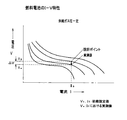
次に、本発明に係る第二実施形態の燃料電池用の水素供給装置について図3から図5を参照して説明する。尚、図3は第二実施形態の燃料電池用の水素供給装置の全体の構成を示す図、図4は、燃料電池のI(電流)−V(電圧)特性の変化から水素品位(水素濃度)の低下を検知する方法を説明するための図、図5は、本発明に係る第二実施形態の燃料電池用の水素供給装置の運転方法を説明するためのフローチャートである。
第二実施形態の燃料電池用の水素供給装置と第一実施形態の燃料電池用の水素供給装置との構成の違いは、図3に示すように、第一実施形態の水素濃度検知手段とは異なる水素濃度検知手段を燃料電池4側に設けた点及び膜分離装置3の出口(バイパス流路BP側の出口)に流量制御弁V1を設けた点である。
尚、第一実施形態の燃料電池用の水素供給装置と同じ部材に付いては同じ符号をつけて説明する。
【0024】
最初に、第二実施形態の燃料電池用の水素供給装置に用いられ、燃料電池のI(電流)−V(電圧)特性の変化から不純物が混入したかどうかを判断する水素濃度検知手段について図4を参照して説明する。
燃料電池4のI(電流)−V(電圧)特性のデータ例を図4に示す。図4の縦軸は電圧(V)、横軸は電流(I)を示す。尚、図4は供給ガス圧を一定としたときの特性曲線である。
燃料電池4の基準となるI−V特性のデータ11は、図3に示す電子制御ユニット10に予めインプットされてROM又はRAMに基準データとして格納される。また、燃料電池4の発電電力の取り出し側に設けられる電流計12、電圧計13の測定データも同様に電子制御ユニット10に電気信号としてインプットされる。
【0025】
ここで使用される電子制御ユニット10は、電気的制御回路、又は、RAM、ROM、CPU(又はMPU)及びI/O等を中心として構成されたマイクロコンピュータからなる電子制御装置である。この制御装置の入力部には、図示しないアクセル開度センサ、バッテリ容量センサ等の燃料電池4の出力に関連する他の電気信号も入力され、これらの入力信号に基づく出力信号により燃料電池用の水素供給装置20が制御される。
尚、燃料電池4で発電した電力は、インバータにより直流から交流に変換され電動機等を駆動する電力として使用される。
【0026】
このような構成からなる水素濃度検知手段を有する第二実施形態の燃料電池用の水素供給装置20に、不純物が混入した水素が供給されると、図4に示すように、一定の電流値Isに対して電圧値Vsが燃料電池4の設計ポイントから垂直方向に下がって例えばVeとなる(但し、燃料電池4へ供給する供給ガス圧一定)。
従って、燃料電池4の発電電力を取り出す負荷側の電流値と電圧値を検知して起電力を監視していれば、一定の電流値に対して起電力の低下があるので、容易に不純物の混入を検知することができる。
【0027】
次に、第二実施形態の燃料電池用の水素供給装置の運転方法について図3及び図5を参照して説明する。尚、予め高圧水素供給型の充填所で水素充填口5から燃料電池車両に搭載された水素貯蔵容器2に高圧の水素が供給・貯蔵されている(例えば充填圧力35MPaG)。
(1)車両のイグニッションスィッチON(S10)。
(2)燃料電池4への水素の供給を開始し、前記した水素濃度検知手段により水素品位(水素濃度)の検知を開始する(S11)。
(3)次に、水素濃度検知手段(燃料電池の基準I−V特性の変化から求めた起電力の低下の有無により検知)により、燃料電池4に供給される水素品位(水素濃度)が燃料電池4の要求する要求品位(要求水素濃度)以上かどうかを判定する(S12)。
(4)要求品位(要求水素濃度)以上の場合は、燃料電池4への水素供給を継続して行う(S13)。
(5)水素品位(水素濃度)が燃料電池4の要求する要求品位未満の場合は、切り替え手段である三方弁6により水素供給流路HPをバイパス流路BP側に切り替え、水素分離器である膜分離装置3を作動する(S14)。
(6)このとき、水素の流量検知手段であるサーマルマスフローメータ7の出力信号(又は三方弁6の切替信号)を使用して、膜分離装置3が運転中であること及び水素品位(水素濃度)が低下したことが運転者にわかるように報知手段、例えば運転コンソールのインストルメントパネル8に表示する(S15)。
(7)燃料電池4へ供給している水素品位(水素濃度)が、燃料電池4の要求する品位以上かどうかを基準I−V特性から求めた起電力と実際に測定した電流値及び電圧値とから求めた起電力とを比較して判定する(S16)。
(8)燃料電池4へ供給している水素品位(水素濃度)が、燃料電池4の要求する品位以上の場合は、バイパス流路BPに設けられた膜分離装置3を経由して燃料電池4に水素を供給するのを継続する(S17)。
(9)膜分離装置3を作動したにも拘わらず、燃料電池4への水素投入量と燃料電池4の発電特性とから水素品位(水素濃度)が低いと判定された場合には膜分離装置異常の表示を報知手段、例えば運転席コンソールのインストルメントパネル8に行い(S18)、燃料電池4へ供給する水素量を制御弁V1を介して制限する(S19)。
【0028】
このような構成と作用を有する第二実施形態の燃料電池用の水素供給装置によれば、
(1)水素濃度検知手段として燃料電池4の発電電流に対する起電力を検知し、前記起電力が通常の場合と比較して低い場合は、水素中の水素濃度が所定濃度よりも低いと判定することにより、水素供給流路HPやバイパス流路BPの膜分離装置3の後流側から不純物の混入があっても確実に不純物の混入の有無を判断することができる。従って、燃料電池の要求する高品位(高純度)の水素を確実に燃料電池に供給することができる。
(2)また、バイパス流路BPを介して燃料電池4へ水素が供給されていることを検知し、その検知結果を報知する報知手段として運転コンソールのインストルメントパネル8を備えたことにより、燃料電池使用者である運転者及び水素充填所の貯蔵施設管理者に警告することができる。
【0029】
次に、本発明に係る第三実施形態の燃料電池用の水素供給装置について図6及び図7を参照して説明する。尚、図6は第三実施形態の燃料電池用の水素供給装置の全体の構成を示す図、図7は、本発明に係る第三実施形態の燃料電池用の水素供給装置の運転方法を説明するためのフローチャートである。
第三実施形態の燃料電池用の水素供給装置30は、第一実施形態の燃料電池用の水素供給装置と第二実施形態の燃料電池用の水素供給装置とを合わせたものである。すなわち、2つの異なる水素濃度検知手段を、水素貯蔵容器2と燃料電池4の発電電力の取り出し側にそれぞれ設けたものである。
【0030】
次に、このように構成される第三実施形態の燃料電池用の水素供給装置30の運転方法について図7を参照して説明する。尚、予め高圧水素供給型の充填所で水素充填口5から燃料電池車両に搭載された水素貯蔵容器2に高圧の水素が供給・貯蔵されている(例えば充填圧力35MPaG)。
(1)車両のイグニッションスィッチON(S20)。
(2)燃料電池4への水素の供給を開始し、水素品位(水素濃度)を水素濃度検知手段であるプロセスガスクロ9で検知するのを開始する(S21)。
前記水素濃度検知手段としては、例えばプロトン導電体を使用した水素濃度計、質量分析計等も使用できるが、本実施形態ではプロセスガスクロ9を使用している。
(3)プロセスガスクロ9により、水素貯蔵容器2内の水素品位(水素濃度)が燃料電池4の要求する要求品位(要求水素濃度)以上かどうかを判定する(S22)。
(4)水素品位(水素濃度)が燃料電池4の要求品位以上の場合は、燃料電池4への水素の供給を継続する(S23)。
(5)水素品位(水素濃度)が燃料電池4の要求する要求品位未満の場合は、水素供給流路HPとバイパス流路BPとを選択的に切り替える切替手段である三方弁6により水素供給流路HPをバイパス流路BP側に切り替えて、水素分離器である膜分離装置3を作動する(S24)。
(6)このとき膜分離装置3が運転中であること及び水素品位(水素濃度)が低下したことが運転者にわかるように報知手段、例えば運転コンソールのインストルメントパネル8に表示する(S25)。
(7)前記した水素濃度検知手段(燃料電池の基準I−V特性の変化から求めた起電力の低下の有無により検知)により、燃料電池4に供給される水素品位(水素濃度)が燃料電池4の要求する要求品位(要求水素濃度)以上かどうかを判定する(S26)。
(8)要求品位以上(要求水素濃度以上)の場合は、燃料電池4への水素の供給を継続して行う(S27)。
(9)膜分離装置3を作動したにも拘わらず、燃料電池4への水素投入量と燃料電池4の発電特性から水素品位(水素濃度)が低いと判断された場合には水素分離器である膜分離装置3が異常である表示を報知手段、例えば運転席コンソールのインストルメントパネル8に行い(S28)、燃料電池4へ供給する水素量を流量制御弁V1により制限する(S29)。
【0031】
このような構成と作用を有する第三実施形態の燃料電池用の水素供給装置によれば、
(1)水素貯蔵タンク2内の水素品位(水素濃度)が低いときには、水素分離器である膜分離装置3を備えたバイパス流路BPを介して水素を燃料電池4へ供給し、その旨を報知手段により運転者に知らせることができる。
(2)また、膜分離装置3を備えたバイパス流路BPを介して燃料電池4へ水素を供給しても、燃料電池4での発電電力量などから水素の品位を逆算したときに水素品位(水素濃度)が低いときには、その旨を報知手段により運転者に知らせた後、燃料電池4へ供給する水素量を制限することができる。
(3)さらに水素分離器である膜分離装置3のメンテナンスを促進することで燃料電池車両を好適に運転することが可能となる。
(4)また、バイパス流路BPを介して燃料電池4へ水素が供給されていることを検知し、その検知結果を報知する報知手段として運転コンソールのインストルメントパネル8を備えたことにより、燃料電池使用者である運転者及び水素充填所の貯蔵施設管理者に警告することができる。
【0032】
以上、第一実施形態から第三実施形態までの燃料電池用の水素供給装置について説明したが、本発明に係る燃料電池用の水素供給装置はこれに限定されるものでなく、本発明の技術的範囲を逸脱しない範囲で適宜変更して実施可能である。
例えば、切替手段である三方弁6の代わりに、水素供給流路HP及びバイパス流路BPのそれぞれに電磁弁を設けて水素の流路を切り替えるようにすることもできる。
【0033】
【発明の効果】
以上の構成と作用からなる本発明によれば、以下の効果を奏する。
1.請求項1に記載の発明によれば、燃料電池車両に搭載された水素貯蔵容器と、該水素貯蔵容器から燃料電池に水素を供給可能にする水素供給流路とを備えた燃料電池用の水素供給装置において、前記水素供給流路と並列して水素を前記燃料電池へ供給するバイパス流路と、水素透過膜を含み、該水素透過膜を透過した水素を前記燃料電池へ供給し、透過しなかった水素を排出する水素分離器を前記バイパス流路に備え、前記水素供給流路と前記バイパス流路とを選択的に切り替える切替手段を備えたことにより、必要に応じて前記水素供給流路と前記水素分離器を備えた前記バイパス流路とを選択的に切り替えることができる。
その結果、常時水素分離器を運転しなくてもよくなるので水素貯蔵容器から燃料電池へ供給する水素の利用効率が向上する。
2.また、燃料電池へ供給する水素の濃度を検知する水素濃度検知手段を備え、水素中の水素濃度が所定濃度よりも低いと判定したときは、バイパス流路を介して前記燃料電池へ水素を供給するように切替手段を切り替えることにより、燃料電池の要求する高品位(高純度)の水素を燃料電池に供給することができる。
3.請求項2に記載の発明によれば、水素濃度検知手段として燃料電池の発電電流に対する起電力を検知し、前記起電力が通常の場合と比較して低い場合は、水素中の水素濃度が所定濃度よりも低いと判定することにより、水素供給流路やバイパス流路に備えた水素分離器の後流側から系内に不純物の混入があっても確実に不純物の混入の有無を判断することができる。従って、燃料電池の要求する高品位(高純度)の水素を確実に燃料電池に供給することができる。
【図面の簡単な説明】
【図1】本発明に係る第一実施形態の燃料電池用の水素供給装置の全体の構成を示す図である。
【図2】本発明に係る第一実施形態の燃料電池用の水素供給装置の運転方法を説明するためのフローチャートである。
【図3】本発明に係る第二実施形態の燃料電池用の水素供給装置の全体の構成を示す図である。
【図4】燃料電池のI−V特性の変化から水素品位(水素濃度)の低下を検知する方法を説明するための図である。
【図5】本発明に係る第二実施形態の燃料電池用の水素供給装置の運転方法を説明するためのフローチャートである。
【図6】本発明に係る第三実施形態の燃料電池用の水素供給装置の全体の構成を示す図である。
【図7】本発明に係る第三実施形態の燃料電池用の水素供給装置の運転方法を説明するためのフローチャートである。
【図8】従来の水素分離器の一例を示す図である。
【符号の説明】
1,20,30, 燃料電池用の水素供給装置
2 水素貯蔵容器
3 膜分離装置(水素分離器)
4 燃料電池
5 水素充填口
6 三方弁(切替手段)
7 マスフローメータ(流量検知手段)
8 インストルメントパネル(報知手段)
9 プロセスガスクロ(水素濃度検知手段)
10 電子制御ユニット
11 燃料電池基準I−V特性データ
12 電流計
13 電圧計
V1 流量制御弁[0001]
BACKGROUND OF THE INVENTION
The present invention relates to a hydrogen supply device for a fuel cell mounted on a fuel cell vehicle, and more particularly, a hydrogen separator that permeates hydrogen so that hydrogen supplied to the fuel cell does not become a predetermined quality (predetermined concentration) or less. The present invention relates to a hydrogen supply device for a fuel cell comprising:
[0002]
[Prior art]
In recent years, solid polymer fuel cells have attracted attention as power sources for electric vehicles. A polymer electrolyte fuel cell (PEFC) can generate electric power even at room temperature, and is being put into practical use for various applications.
[0003]
In general, a fuel cell system has a structure in which a cathode electrode is partitioned on one side and an anode electrode is partitioned on the other side of a solid polymer electrolyte membrane, and oxygen in the air supplied to the cathode electrode and the anode This system drives an external load with electric power generated by a chemical reaction with hydrogen supplied to an electrode.
[0004]
As a general method for securing a hydrogen supply source as fuel for such a fuel cell,
(1) Pure hydrogen type; a method of supplying hydrogen to a hydrogen storage material such as a liquid hydrogen tank, a high pressure tank, or a hydrogen storage alloy using pure hydrogen such as liquid hydrogen or high pressure hydrogen, and using it as a supply source;
(2) Reformation method; a method for producing hydrogen as a supply source by steam reforming using a hydrocarbon, for example, an aqueous methanol solution,
Etc.
[0005]
On the other hand, as a hydrogen supply method in a high-pressure hydrogen supply type hydrogen filling station that supplies high-pressure hydrogen to a hydrogen storage container or the like mounted on a vehicle,
(1) A method of producing hydrogen with a complex, etc., liquefying the produced hydrogen, transporting the liquefied hydrogen to a hydrogen filling station, and supplying the liquid hydrogen by vaporizing and increasing the pressure at the hydrogen filling station,
(2) A method of reforming an organic liquid fuel such as natural gas, organic liquid fuel such as methanol or gasoline on-site using a reformer (reformer), and increasing the pressure of the reformed gas.
(3) A method of extracting hydrogen on-site from an organic or metal complex chemical hydride and supplying the extracted hydrogen under pressure,
Etc.
[0006]
[Problems to be solved by the invention]
However, in these hydrogen supply methods for supplying high-pressure hydrogen, impurities may be mixed into hydrogen for the following reasons. That is,
(1) When an organic liquid fuel such as natural gas, methanol, or gasoline is reformed on-site using a reformer (reformer), carbon monoxide gas is generated in the fuel reforming process. This gas is mixed as an impurity.
(2) Oil components such as lubricating oil used for lubricating the hydrogen compressor are mixed as impurities in the compression step for increasing the pressure of hydrogen.
(3) A trace amount of water, dust, etc. are mixed as impurities from the hydrogen supply hose.
(4) Further, by-products other than hydrogen are generated due to a malfunction of the reforming catalyst of the reformer (reformer) of the hydrogen production process, and these are mixed into the hydrogen as impurities.
(5) It is also assumed that these impurities accumulate and make the quality (hydrogen concentration) of the supplied hydrogen lower than the allowable hydrogen quality (allowable hydrogen concentration) of the fuel cell.
[0007]
When these low-grade hydrogens (low-purity hydrogen) having a large impurity content are used, the fuel cell has a serious performance deterioration.
For example, when impurities are mixed into hydrogen fuel in a fuel cell and the chemical reaction at the electrode is suppressed by the impurities, the generated voltage of the fuel cell is reduced, that is, the output of the fuel cell is reduced. Therefore, in a fuel cell (on-board type fuel cell) having a hydrogen storage / supply device such as one mounted on a vehicle, a utilization device against contamination of hydrogen supplied from a hydrogen filling facility (on-site) It is necessary to take measures on the side (onboard) to suppress the supply of impurities to the fuel cell.
[0008]
As a hydrogen separator for separating only hydrogen from low-grade hydrogen, a
[0009]
The present invention has been made to solve the above-described problems, and can supply hydrogen so that the hydrogen supplied to the fuel cell always has a predetermined quality (predetermined concentration) or more, and further improves the utilization efficiency of hydrogen supplied to the fuel cell. An object of the present invention is to provide a hydrogen supply device for a fuel cell that can be improved.
[0010]
[Means for Solving the Problems]
The hydrogen supply device for a fuel cell according to
[0011]
According to the first aspect of the present invention, a hydrogen supply for a fuel cell comprising a hydrogen storage container mounted on a fuel cell vehicle, and a hydrogen supply channel that allows hydrogen to be supplied from the hydrogen storage container to the fuel cell. In the apparatus, the apparatus includes a bypass flow path for supplying hydrogen to the fuel cell in parallel with the hydrogen supply flow path, and a hydrogen permeable membrane, and supplies hydrogen that has passed through the hydrogen permeable membrane to the fuel cell and does not permeate. Provided with a hydrogen separator for discharging the hydrogen in the bypass flow path, and provided with a switching means for selectively switching the hydrogen supply flow path and the bypass flow path. The bypass channel provided with the hydrogen separator can be selectively switched.
As a result, since it is not necessary to always operate the hydrogen separator, the utilization efficiency of hydrogen supplied from the hydrogen storage container to the fuel cell is improved.
[0013]
Also, Hydrogen concentration detecting means for detecting the concentration of hydrogen supplied to the fuel cell is provided, and when it is determined that the hydrogen concentration in the hydrogen is lower than a predetermined concentration, hydrogen is supplied to the fuel cell via the bypass channel. By switching the switching means, high quality (high purity) hydrogen required by the fuel cell can be supplied to the fuel cell.
[0014]
[0015]
[0016]
DETAILED DESCRIPTION OF THE INVENTION
An embodiment of a hydrogen supply device for a fuel cell according to the present invention will be described with reference to FIGS.
First, the hydrogen separator according to the present invention will be described.
In general, methods for separating / removing impurities in hydrogen include membrane separation, PSA (pressure fluctuation adsorption), cryogenic separation, and solution absorption.
Among these, the membrane separation method has few mechanically operating parts and has a relatively simple device configuration. Therefore, in this embodiment, a
[0017]
As described above, when the pressure on the low-grade hydrogen side is constant, the
Therefore, the
[0018]
Next, the material of the separation membrane used in the
[0019]
The Pd-based metal film forms a β phase (hydride phase) having poor ductility when high-pressure hydrogen is supplied at a low temperature. Therefore, a high temperature (eg, 300 C.) is preferable. Thus, for example, the operation efficiency of the
In the present embodiment, a hollow fiber composite membrane using polysulfone as a substrate and silicone rubber as a coating material is used as the hydrogen permeable membrane of the
[0020]
Hereinafter, an embodiment of a hydrogen supply device for a fuel cell according to the present invention mounted on a vehicle will be described.
First, a hydrogen supply device for a fuel cell according to a first embodiment of the present invention will be described with reference to FIGS. 1 and 2. 1 is a diagram showing the overall configuration of the hydrogen supply device for a fuel cell according to the first embodiment of the present invention, and FIG. 2 is an operation of the hydrogen supply device for the fuel cell of the first embodiment according to the present invention. It is a flowchart for demonstrating a method.
As shown in FIG. 1, the
A
Hydrogen concentration detection means for detecting the hydrogen concentration in the hydrogen storage container 2 (hydrogen to be supplied to the fuel cell 4 from now on);
A hydrogen supply flow path HP that enables hydrogen to be supplied from the
Two regulators RG1, RG2 provided in the hydrogen supply flow path HP for adjusting the pressure of hydrogen supplied to the fuel cell 4,
A bypass flow path BP for supplying hydrogen to the fuel cell 4 in parallel with the hydrogen supply flow path HP;
A
A flow rate detection means 7 provided on the downstream side of the
A three-way valve 6 which is switching means for selectively switching between the hydrogen supply flow path HP and the bypass flow path BP;
The main part consists of
[0021]
The operation method of the
Note that high-pressure hydrogen is supplied and stored in advance from the
(1) The vehicle ignition switch is turned on (S1).
(2) At this time, the hydrogen quality (hydrogen concentration) is detected by the hydrogen concentration detecting means (S2). As the hydrogen concentration detection means, for example, a hydrogen concentration meter using a proton conductor, a mass spectrometer, a process gas chromatograph or the like can be used. In this embodiment, a process gas chromatograph 9 is used.
(3) The process gas chromatography 9 determines whether the hydrogen quality (hydrogen concentration) in the
As a hydrogen concentration detection method, either the hydrogen concentration or the impurity concentration (for example, carbon monoxide CO concentration) may be detected.
(4) As a result of detecting the hydrogen concentration, if hydrogen is higher than the required quality (required hydrogen concentration), supply of hydrogen to the fuel cell 4 is started (S4).
(5) If the hydrogen quality (hydrogen concentration) is equal to or higher than the required quality (required hydrogen concentration) of the fuel cell 4, the supply of hydrogen is continued as it is (S5).
(6) Three-way switching means for selectively switching between the hydrogen supply flow path HP and the bypass flow path BP when the hydrogen quality (hydrogen concentration) is less than the required quality (required hydrogen concentration) required by the fuel cell 4 The hydrogen supply flow path HP is switched to the bypass flow path BP side by the valve 6 to operate the
(7) At this time, the output signal (or the switching signal of the three-way valve 6) of the thermal
(8) Supply of hydrogen from the
[0022]
According to the hydrogen supply device for a fuel cell of the first embodiment having such a configuration and action,
(1) The hydrogen supply flow path HP and the bypass flow path BP provided with the
(2) The process gas chromatography 9 which is a hydrogen concentration detection means for detecting the concentration of hydrogen supplied to the fuel cell 4 is provided in the
(3) Further, by providing an
[0023]
Next, a hydrogen supply device for a fuel cell according to a second embodiment of the present invention will be described with reference to FIGS. 3 is a diagram showing the overall configuration of the hydrogen supply device for a fuel cell according to the second embodiment, and FIG. 4 is a graph showing hydrogen quality (hydrogen concentration) based on changes in the I (current) -V (voltage) characteristics of the fuel cell. FIG. 5 is a flowchart for explaining an operation method of the hydrogen supply device for a fuel cell according to the second embodiment of the present invention.
The difference in configuration between the hydrogen supply device for the fuel cell of the second embodiment and the hydrogen supply device for the fuel cell of the first embodiment is different from the hydrogen concentration detection means of the first embodiment as shown in FIG. A different hydrogen concentration detection means is provided on the fuel cell 4 side, and a flow control valve V1 is provided on the outlet of the membrane separation device 3 (the outlet on the bypass flow path BP side).
The same members as those in the hydrogen supply device for a fuel cell according to the first embodiment will be described with the same reference numerals.
[0024]
First, a hydrogen concentration detection unit used in the hydrogen supply device for a fuel cell according to the second embodiment, which determines whether impurities are mixed from a change in I (current) -V (voltage) characteristics of the fuel cell. This will be described with reference to FIG.
A data example of the I (current) -V (voltage) characteristics of the fuel cell 4 is shown in FIG. In FIG. 4, the vertical axis represents voltage (V) and the horizontal axis represents current (I). FIG. 4 is a characteristic curve when the supply gas pressure is constant.
The IV
[0025]
The
The electric power generated by the fuel cell 4 is converted from direct current to alternating current by an inverter and used as electric power for driving an electric motor or the like.
[0026]
When hydrogen mixed with impurities is supplied to the
Therefore, if the electromotive force is monitored by detecting the current value and the voltage value on the load side for taking out the generated power of the fuel cell 4, the electromotive force is reduced with respect to a constant current value. Mixing can be detected.
[0027]
Next, an operation method of the hydrogen supply device for a fuel cell according to the second embodiment will be described with reference to FIGS. 3 and 5. Note that high-pressure hydrogen is supplied and stored in advance from the
(1) Turn on the ignition switch of the vehicle (S10).
(2) The supply of hydrogen to the fuel cell 4 is started, and detection of hydrogen quality (hydrogen concentration) is started by the hydrogen concentration detection means described above (S11).
(3) Next, the hydrogen quality (hydrogen concentration) supplied to the fuel cell 4 is determined by the hydrogen concentration detection means (detected based on the presence or absence of a decrease in electromotive force obtained from the change in the reference IV characteristics of the fuel cell). It is determined whether or not the required quality (required hydrogen concentration) required by the battery 4 is exceeded (S12).
(4) If the required quality (required hydrogen concentration) or higher, hydrogen supply to the fuel cell 4 is continued (S13).
(5) When the hydrogen quality (hydrogen concentration) is less than the required quality required by the fuel cell 4, the hydrogen supply flow path HP is switched to the bypass flow path BP side by the three-way valve 6 serving as a switching means, thereby providing a hydrogen separator. The
(6) At this time, the output signal of the thermal
(7) The electromotive force obtained from the reference IV characteristics and the actually measured current value and voltage value as to whether the hydrogen quality (hydrogen concentration) supplied to the fuel cell 4 is higher than the quality required by the fuel cell 4 Are compared with the electromotive force obtained from the above (S16).
(8) When the hydrogen quality (hydrogen concentration) supplied to the fuel cell 4 is higher than the quality required by the fuel cell 4, the fuel cell 4 passes through the
(9) When it is determined that the hydrogen quality (hydrogen concentration) is low from the amount of hydrogen input to the fuel cell 4 and the power generation characteristics of the fuel cell 4 despite the operation of the
[0028]
According to the hydrogen supply device for a fuel cell of the second embodiment having such a configuration and action,
(1) An electromotive force with respect to the generated current of the fuel cell 4 is detected as a hydrogen concentration detection means, and when the electromotive force is lower than a normal case, it is determined that the hydrogen concentration in hydrogen is lower than a predetermined concentration. Thus, even if impurities are mixed in from the downstream side of the
(2) Further, by providing the
[0029]
Next, a hydrogen supply device for a fuel cell according to a third embodiment of the present invention will be described with reference to FIGS. FIG. 6 is a diagram showing the overall configuration of the hydrogen supply device for a fuel cell according to the third embodiment, and FIG. 7 is a diagram illustrating an operation method of the hydrogen supply device for a fuel cell according to the third embodiment of the present invention. It is a flowchart for doing.
The fuel cell
[0030]
Next, an operation method of the
(1) The vehicle ignition switch is turned on (S20).
(2) The supply of hydrogen to the fuel cell 4 is started, and detection of the hydrogen quality (hydrogen concentration) by the process gas chromatograph 9 that is a hydrogen concentration detection means is started (S21).
As the hydrogen concentration detection means, for example, a hydrogen concentration meter using a proton conductor, a mass spectrometer, or the like can be used. In this embodiment, a process gas chromatograph 9 is used.
(3) The process gas chromatography 9 determines whether the hydrogen quality (hydrogen concentration) in the
(4) If the hydrogen quality (hydrogen concentration) is equal to or higher than the required quality of the fuel cell 4, the supply of hydrogen to the fuel cell 4 is continued (S23).
(5) When the hydrogen quality (hydrogen concentration) is less than the required quality required by the fuel cell 4, the hydrogen supply flow is provided by the three-way valve 6 which is a switching means for selectively switching between the hydrogen supply flow path HP and the bypass flow path BP. The path HP is switched to the bypass flow path BP side, and the
(6) At this time, information is displayed on the
(7) The hydrogen quality (hydrogen concentration) supplied to the fuel cell 4 is determined by the above-described hydrogen concentration detection means (detected by the presence or absence of a decrease in electromotive force obtained from the change in the reference IV characteristics of the fuel cell). It is determined whether or not the required quality (required hydrogen concentration) of 4 is required (S26).
(8) If the required quality or higher (required hydrogen concentration or higher), hydrogen is continuously supplied to the fuel cell 4 (S27).
(9) When it is determined that the hydrogen quality (hydrogen concentration) is low from the amount of hydrogen input to the fuel cell 4 and the power generation characteristics of the fuel cell 4 despite the operation of the
[0031]
According to the hydrogen supply device for a fuel cell of the third embodiment having such a configuration and action,
(1) When the hydrogen quality (hydrogen concentration) in the
(2) Even if hydrogen is supplied to the fuel cell 4 via the bypass flow path BP provided with the
(3) The fuel cell vehicle can be preferably operated by further promoting the maintenance of the
(4) Further, by providing the
[0032]
The hydrogen supply device for a fuel cell from the first embodiment to the third embodiment has been described above. However, the hydrogen supply device for a fuel cell according to the present invention is not limited to this, and the technology of the present invention. The present invention can be implemented with appropriate modifications without departing from the scope.
For example, instead of the three-way valve 6 that is a switching means, an electromagnetic valve may be provided in each of the hydrogen supply flow path HP and the bypass flow path BP to switch the hydrogen flow path.
[0033]
【The invention's effect】
According to the present invention having the above configuration and operation, the following effects can be obtained.
1. According to the first aspect of the present invention, a hydrogen for a fuel cell comprising a hydrogen storage container mounted on a fuel cell vehicle and a hydrogen supply channel that enables hydrogen to be supplied from the hydrogen storage container to the fuel cell. The supply apparatus includes a bypass flow path for supplying hydrogen to the fuel cell in parallel with the hydrogen supply flow path, and a hydrogen permeable membrane, and supplies the hydrogen that has permeated the hydrogen permeable membrane to the fuel cell and permeates the fuel cell. A hydrogen separator that discharges hydrogen that has not been provided is provided in the bypass flow path, and switching means that selectively switches between the hydrogen supply flow path and the bypass flow path is provided. And the bypass flow path provided with the hydrogen separator can be selectively switched.
As a result, since it is not necessary to always operate the hydrogen separator, the utilization efficiency of hydrogen supplied from the hydrogen storage container to the fuel cell is improved.
2. Also And a hydrogen concentration detecting means for detecting the concentration of hydrogen supplied to the fuel cell, and when it is determined that the hydrogen concentration in the hydrogen is lower than a predetermined concentration, hydrogen is supplied to the fuel cell via the bypass channel. By switching the switching means as described above, high quality (high purity) hydrogen required by the fuel cell can be supplied to the fuel cell.
3.
[Brief description of the drawings]
FIG. 1 is a diagram showing the overall configuration of a hydrogen supply device for a fuel cell according to a first embodiment of the present invention.
FIG. 2 is a flowchart for explaining a method of operating the hydrogen supply device for a fuel cell according to the first embodiment of the present invention.
FIG. 3 is a diagram showing an overall configuration of a hydrogen supply device for a fuel cell according to a second embodiment of the present invention.
FIG. 4 is a diagram for explaining a method of detecting a decrease in hydrogen quality (hydrogen concentration) from a change in IV characteristics of a fuel cell.
FIG. 5 is a flowchart for explaining an operation method of a hydrogen supply device for a fuel cell according to a second embodiment of the present invention.
FIG. 6 is a diagram showing the overall configuration of a hydrogen supply device for a fuel cell according to a third embodiment of the present invention.
FIG. 7 is a flowchart for explaining an operating method of a hydrogen supply device for a fuel cell according to a third embodiment of the present invention.
FIG. 8 is a diagram showing an example of a conventional hydrogen separator.
[Explanation of symbols]
1, 20, 30, Hydrogen supply device for fuel cell
2 Hydrogen storage container
3 Membrane separator (hydrogen separator)
4 Fuel cell
5 Hydrogen filling port
6 Three-way valve (switching means)
7 Mass flow meter (flow rate detection means)
8 Instrument panel (notification means)
9 Process gas chromatography (hydrogen concentration detection means)
10 Electronic control unit
11 Fuel cell reference IV characteristics data
12 Ammeter
13 Voltmeter
V1 Flow control valve
Claims (2)
前記水素供給流路と並列して水素を前記燃料電池へ供給するバイパス流路と、
前記バイパス流路に備えられ、かつ、水素透過膜を含み、該水素透過膜を透過した水素を前記燃料電池へ供給し、透過しなかった水素を排出する水素分離器と、
前記水素供給流路と前記バイパス流路とを選択的に切り替える切替手段と、
前記燃料電池へ供給される水素の濃度を検知する水素濃度検知手段と、
を備え、
前記燃料電池へ供給される水素中の水素濃度が所定濃度よりも低いと判定したときは、前記バイパス流路を介して前記燃料電池へ水素を供給するように前記切替手段を切り替えることを特徴とする燃料電池用の水素供給装置。In a hydrogen supply device for a fuel cell, comprising: a hydrogen storage container mounted on a fuel cell vehicle; and a hydrogen supply channel that enables hydrogen to be supplied from the hydrogen storage container to the fuel cell.
A bypass flow path for supplying hydrogen to the fuel cell in parallel with the hydrogen supply flow path;
A hydrogen separator that is provided in the bypass channel and includes a hydrogen permeable membrane, supplies hydrogen that has passed through the hydrogen permeable membrane to the fuel cell, and discharges hydrogen that has not permeated;
Switching means for selectively switching between the hydrogen supply flow path and the bypass flow path ;
Hydrogen concentration detecting means for detecting the concentration of hydrogen supplied to the fuel cell;
With
Wherein when the fuel concentration of hydrogen in the hydrogen supplied to the battery is determined to be lower than a predetermined concentration, that you switch the switching means to supply hydrogen to the fuel cell via the bypass channel A hydrogen supply device for a fuel cell.
Priority Applications (2)
| Application Number | Priority Date | Filing Date | Title |
|---|---|---|---|
| JP2001325756A JP3807668B2 (en) | 2001-10-24 | 2001-10-24 | Hydrogen supply device for fuel cell |
| US10/280,345 US7175928B2 (en) | 2001-10-24 | 2002-10-24 | Hydrogen supplying apparatus for fuel cell |
Applications Claiming Priority (1)
| Application Number | Priority Date | Filing Date | Title |
|---|---|---|---|
| JP2001325756A JP3807668B2 (en) | 2001-10-24 | 2001-10-24 | Hydrogen supply device for fuel cell |
Publications (3)
| Publication Number | Publication Date |
|---|---|
| JP2003132929A JP2003132929A (en) | 2003-05-09 |
| JP2003132929A5 JP2003132929A5 (en) | 2005-06-09 |
| JP3807668B2 true JP3807668B2 (en) | 2006-08-09 |
Family
ID=19142253
Family Applications (1)
| Application Number | Title | Priority Date | Filing Date |
|---|---|---|---|
| JP2001325756A Expired - Fee Related JP3807668B2 (en) | 2001-10-24 | 2001-10-24 | Hydrogen supply device for fuel cell |
Country Status (2)
| Country | Link |
|---|---|
| US (1) | US7175928B2 (en) |
| JP (1) | JP3807668B2 (en) |
Families Citing this family (13)
| Publication number | Priority date | Publication date | Assignee | Title |
|---|---|---|---|---|
| US7318970B2 (en) * | 2003-04-04 | 2008-01-15 | Texaco Inc. | Architectural hierarchy of control for a fuel processor |
| US9029028B2 (en) * | 2003-12-29 | 2015-05-12 | Honeywell International Inc. | Hydrogen and electrical power generator |
| JP4405269B2 (en) * | 2004-01-07 | 2010-01-27 | 中国電力株式会社 | Energy trading method using computer network |
| JP2005302422A (en) * | 2004-04-08 | 2005-10-27 | Nissan Motor Co Ltd | Fuel cell system |
| US7763087B2 (en) * | 2004-12-17 | 2010-07-27 | Texaco Inc. | Safety system architecture for a hydrogen fueling station |
| US7438079B2 (en) * | 2005-02-04 | 2008-10-21 | Air Products And Chemicals, Inc. | In-line gas purity monitoring and control system |
| KR100722109B1 (en) * | 2005-09-28 | 2007-05-25 | 삼성에스디아이 주식회사 | Control device for fuel cell system and related method |
| JP5233094B2 (en) * | 2006-08-10 | 2013-07-10 | 日産自動車株式会社 | Hydrogen generation system, fuel cell system and fuel cell vehicle |
| GB2496635A (en) | 2011-11-17 | 2013-05-22 | Intelligent Energy Ltd | Fan mounting in fuel cell stack assemblies |
| GB2497787B (en) * | 2011-12-21 | 2019-06-26 | Intelligent Energy Ltd | Hydrogen quality monitor |
| DE102017001056A1 (en) * | 2017-02-04 | 2018-08-09 | Diehl Aerospace Gmbh | Method and device for generating electrical energy |
| CN108100994A (en) * | 2018-02-02 | 2018-06-01 | 吴海雷 | A kind of hydrogen recycling purification system and its control method |
| JP7351607B2 (en) * | 2018-09-03 | 2023-09-27 | トヨタ自動車株式会社 | Fuel cell system and fuel gas quality determination method |
Family Cites Families (10)
| Publication number | Priority date | Publication date | Assignee | Title |
|---|---|---|---|---|
| JPH05299105A (en) | 1992-04-23 | 1993-11-12 | Mitsubishi Heavy Ind Ltd | Fuel battery |
| JP4000608B2 (en) | 1996-11-07 | 2007-10-31 | トヨタ自動車株式会社 | Hydrogen production filling device and electric vehicle |
| JP3629949B2 (en) | 1998-05-07 | 2005-03-16 | 日産自動車株式会社 | Fuel cell system |
| JP2001015142A (en) | 1999-06-30 | 2001-01-19 | Mitsubishi Heavy Ind Ltd | Running method of fuel-cell vehicle and fuel-cell vehicle |
| US6451464B1 (en) * | 2000-01-03 | 2002-09-17 | Idatech, Llc | System and method for early detection of contaminants in a fuel processing system |
| US20020114984A1 (en) * | 2001-02-21 | 2002-08-22 | Edlund David J. | Fuel cell system with stored hydrogen |
| US6673479B2 (en) * | 2001-03-15 | 2004-01-06 | Hydrogenics Corporation | System and method for enabling the real time buying and selling of electricity generated by fuel cell powered vehicles |
| US6586124B2 (en) * | 2001-03-26 | 2003-07-01 | Motorola Inc | Method and apparatus for cold temperature operation of fuel cells utilizing hydrides having different heat capacities |
| JP2003109630A (en) * | 2001-09-27 | 2003-04-11 | Equos Research Co Ltd | Fuel cell system |
| US7470648B2 (en) * | 2002-02-13 | 2008-12-30 | Battelle Memorial Institute | Reforming catalysts |
-
2001
- 2001-10-24 JP JP2001325756A patent/JP3807668B2/en not_active Expired - Fee Related
-
2002
- 2002-10-24 US US10/280,345 patent/US7175928B2/en not_active Expired - Fee Related
Also Published As
| Publication number | Publication date |
|---|---|
| US7175928B2 (en) | 2007-02-13 |
| US20030077492A1 (en) | 2003-04-24 |
| JP2003132929A (en) | 2003-05-09 |
Similar Documents
| Publication | Publication Date | Title |
|---|---|---|
| US6168705B1 (en) | Electrochemical gas purifier | |
| JP3807668B2 (en) | Hydrogen supply device for fuel cell | |
| US7011693B2 (en) | Control of a hydrogen purifying pressure swing adsorption unit in fuel processor module for hydrogen generation | |
| US20080057359A1 (en) | Flexible fuel cell system configuration to handle multiple fuels | |
| US7887958B2 (en) | Hydrogen-producing fuel cell systems with load-responsive feedstock delivery systems | |
| US7416569B2 (en) | Fuel gas production apparatus and method of starting operation of fuel gas production apparatus | |
| EP1339125A2 (en) | Purging control of fuel cell anode effluent | |
| MX2007007466A (en) | Temperature-based breakthrough detection and pressure swing adsorption systems and fuel processing systems including the same. | |
| WO2014182376A1 (en) | Hydrogen production process with carbon dioxide recovery | |
| US20040197616A1 (en) | Oxidant-enriched fuel cell system | |
| Chen et al. | Hydrogen permeation and recovery from H2–N2 gas mixtures by Pd membranes with high permeance | |
| JP2003130291A (en) | Hydrogen filling device | |
| US7666537B2 (en) | Fuel cell system for preventing hydrogen permeable metal layer degradation | |
| JP2002241106A (en) | Method for controlling injection of oxidizing agent | |
| JP6934719B2 (en) | Systems and methods for producing hydrogen, and fuel cells | |
| JP3629949B2 (en) | Fuel cell system | |
| JP2003163024A (en) | Reform type fuel cell system | |
| Brunetti et al. | A PEMFC and H2 membrane purification integrated plant | |
| US6830675B2 (en) | Method and device for removing carbon monoxide from a gas stream | |
| US20050244765A1 (en) | Method of controlling operation of fuel gas production apparatus | |
| JP4523313B2 (en) | Hydrogen gas production power generation system and operation method thereof | |
| JP3867082B2 (en) | Method for stopping household fuel gas production equipment | |
| JP6247623B2 (en) | Fuel cell system | |
| JPH06223856A (en) | Fuel cell generator | |
| KR20160042488A (en) | Fuel cell system for charging electric vehicle batteries |
Legal Events
| Date | Code | Title | Description |
|---|---|---|---|
| A521 | Request for written amendment filed |
Free format text: JAPANESE INTERMEDIATE CODE: A523 Effective date: 20040825 |
|
| A621 | Written request for application examination |
Free format text: JAPANESE INTERMEDIATE CODE: A621 Effective date: 20040825 |
|
| A977 | Report on retrieval |
Free format text: JAPANESE INTERMEDIATE CODE: A971007 Effective date: 20060126 |
|
| A131 | Notification of reasons for refusal |
Free format text: JAPANESE INTERMEDIATE CODE: A131 Effective date: 20060201 |
|
| A521 | Request for written amendment filed |
Free format text: JAPANESE INTERMEDIATE CODE: A523 Effective date: 20060403 |
|
| TRDD | Decision of grant or rejection written | ||
| A01 | Written decision to grant a patent or to grant a registration (utility model) |
Free format text: JAPANESE INTERMEDIATE CODE: A01 Effective date: 20060510 |
|
| A61 | First payment of annual fees (during grant procedure) |
Free format text: JAPANESE INTERMEDIATE CODE: A61 Effective date: 20060512 |
|
| R150 | Certificate of patent or registration of utility model |
Free format text: JAPANESE INTERMEDIATE CODE: R150 |
|
| FPAY | Renewal fee payment (event date is renewal date of database) |
Free format text: PAYMENT UNTIL: 20090526 Year of fee payment: 3 |
|
| FPAY | Renewal fee payment (event date is renewal date of database) |
Free format text: PAYMENT UNTIL: 20100526 Year of fee payment: 4 |
|
| FPAY | Renewal fee payment (event date is renewal date of database) |
Free format text: PAYMENT UNTIL: 20110526 Year of fee payment: 5 |
|
| FPAY | Renewal fee payment (event date is renewal date of database) |
Free format text: PAYMENT UNTIL: 20110526 Year of fee payment: 5 |
|
| LAPS | Cancellation because of no payment of annual fees |