JP3805696B2 - Electrolyzed water generator - Google Patents
Electrolyzed water generator Download PDFInfo
- Publication number
- JP3805696B2 JP3805696B2 JP2002046356A JP2002046356A JP3805696B2 JP 3805696 B2 JP3805696 B2 JP 3805696B2 JP 2002046356 A JP2002046356 A JP 2002046356A JP 2002046356 A JP2002046356 A JP 2002046356A JP 3805696 B2 JP3805696 B2 JP 3805696B2
- Authority
- JP
- Japan
- Prior art keywords
- electrode
- plate
- electrolytic cell
- liquid
- electrolyzed water
- Prior art date
- Legal status (The legal status is an assumption and is not a legal conclusion. Google has not performed a legal analysis and makes no representation as to the accuracy of the status listed.)
- Expired - Fee Related
Links
Images


Landscapes
- Apparatus For Disinfection Or Sterilisation (AREA)
- Water Treatment By Electricity Or Magnetism (AREA)
Description
【0001】
【発明の属する技術分野】
本発明は、洗浄効果および殺菌効果を有する電解水の生成に関するものである。
【0002】
【従来の技術】
近年、洗浄水として電解水が着目されている。
たとえば、特開2000−317414号の生成装置は、多数の孔を形成した陰電極板と、孔のない陽電極板とを互いに対向させ、両電極板に沿って水を流す。これにより、洗浄効果を持つ電解水が生成される。
【0003】
特開平6−277385号の装置では、陽電極と陰電極との間で長い迷路状の流路を形成し、当該流路に沿って水を流す。これにより、電解水を生成すると共に、オゾンを発生させ、殺菌効果を持つ電解水を生成する。
【0004】
【発明が解決しようとする課題】
しかし、これらの先行技術では、偶発的にオゾンを発生するので、オゾンの濃度を高めるのが難しい。
したがって、本発明の主目的は、洗浄効果を有し、かつ、オゾン濃度の高い電解水を生成する装置を提供することである。
【0005】
特開昭62−227494号の装置は、多数の貫通孔を有する3枚の板状電極を上下に離間させた状態で、水平面に沿って配置し、下から上に向って液体を流す。この装置は、板状電極の下面に気泡が溜まるので、効率が悪いだけでなく、酸素の小さな気泡が上方に昇りにくいので、オゾンが殆ど発生しない。
【0006】
また、特開昭56−786769号の装置は、金属網からなる陽極と陰極の間にスペーサを介挿して、前記金属網に直交する横方向に液体を圧送している。この装置では、液体が金属網に直交する方向に流れるので、液体中のオゾン濃度を高くするためには、多数の金属網を設ける必要がある。そのため、装置が大型化するだけでなく、金属網を固定するための構造も複雑になり、コストアップの要因になる。
したがって、本発明の他の目的は、電解水生成装置の小型化およびコストダウンを図ることである。
【0007】
ところで、特開平11−216483号には、電解水生成部を備えた洗濯機が開示されている。この洗濯機は2枚の電極の極性を定期的に逆転させて、電極の一方的な消耗を防止している。しかし、極性を逆転させる時間については何ら開示がなされておらず、極性の切り替えにより、オゾンの生成効率を高めることはできない。
【0008】
【課題を解決するための手段】
前記目的を達成するために、本発明のある態様の構成を図1を用いて説明する。
本態様は、液体から電解水を生成する電解水生成装置であって、電解槽1、導入部21、電極対11,12、直流電源および導出部22を備えている。前記導入部21は液体を前記電解槽1に圧送する。前記電極対11,12は少なくとも2枚の板状電極11,12を含む。前記板状電極11,12は、前記電解槽1内に概ね鉛直面に沿って、かつ、互いに近接して対面するように配置されている。前記直流電源は、前記板状電極11,12の間に直流電圧を印加する。前記導出部22は、前記液体を電解槽1内で電気分解することにより生成された電解水を前記電解槽1から導出する。本態様は、制御回路を更に備えていてもよく、この場合、前記制御回路は、前記電極対11,12に生じる電位差を0.5秒〜180秒の間隔で切り替えて、前記板状電極11,12間に流れる電流の向きを切り替える。前記各電極11,12には、それぞれ多数の貫通孔61,62が形成されている。前記導入部21は前記電解槽1の下部に設けられている。前記導出部22は前記電解槽1の上部に設けられている。前記電解槽1内には規制板(規制手段)40が設けられている。前記規制手段40は、前記導入部21から電解槽1内に導入され前記導出部22から導出されるまでの液体の流れFが、前記複数の板状電極11,12の貫通孔61,62を通って前記電極対11,12を横切りながら、上昇するように前記液体の流れ方向Fを規制する。
【0009】
本発明において、「板状電極」とは、金属板などの板状の導体に多数の貫通孔を形成した電極板の他に、金属網などを含むことを意味する。
【0010】
水の分子は水素結合によりクラスター(複数個の分子が凝集して形成される分子の集合体)を形成し、巨大分子のような振る舞いをしているといわれている。しかし、水を電気分解すると、次の(1),(2),(3) 式に示す化学反応により、水の分子は酸素ガス、水素ガス及び新たな水分子を生成する。
【0011】
H2 O→H+ +OH- …(1)
2H+ +2e- →H2 …(2)
4OH- →4e- +O2 +2H2 O …(3)
【0012】
このような化学変化を行うことで、クラスターは破壊される。これにより、水の表面張力は減少して界面活性効果が増大し、汚れ物質に対する浸透性が高まる。更に、生成された電解水は、水素ガスや酸素ガス等の多数の微細な気泡を豊富に含んでいるため、キャビテーション(発生した気泡が核になって、無数の真空に近い微小空洞が発生し、これが崩壊する時に衝撃力を発生する)の作用により、汚れの原因である付着物質を洗浄対象物から剥離しやすくする。
なお、電気分解により、水道水の表面張力は0.0722N/mから0.0716N/m程度まで低下し得ることが確認されている。
【0013】
本発明においては、水または水溶液を原水(液体)として用いる。ここで、前記(1) 〜(3) 式の化学反応を得るには原水に導電性が必要であり、したがって、原水自体にイオンが含まれている必要から、「水」としては純水(蒸留水)やイオン交換水を用いることも可能であるが、一般に、水道水や井戸水を用いることができる。また、水溶液としては食塩やクエン酸を添加した水溶液を採用することもできる。
【0014】
水の電気分解量は電極対11,12に流れる電流値に比例する。したがって、強力な電気分解を行うためには、電流値をできる限り大きくする必要がある。そこで、本発明では、印加電圧をあまり上げずに電流を大きくするために、電極11,12間の間隙Δを小さくする。前記電極11,12間の間隔Δは 0.5mm 〜 3.0mm に設定され、より好ましくは 0.5mm〜2mm程度とする。かかる観点から、複数の電極ユニット(電極対11,12ないし電極群)を設けて、電極の面積を大きくするのが好ましい。
【0015】
第1電極板11と第2電極板12とは、互いに概ね平行にかつ対面して配置されており、これにより、前記電極11,12間の間隔Δが略一定となり、電極板11,12の表面が均等に電気分解に寄与する。
なお、「対面」とは、2枚の電極板11,12の間に隔膜が設けられていないことを意味する。
【0016】
一方、電極11,12間の間隙Δを小さくしたことにより、前記間隙Δ内に原水が流れ込み難くなってしまう。そこで、本態様では、複数枚の電極板11,12の各々に多数の貫通孔61,62を設けて、電極11,12間の流路6に水が流入し易い構造としている。
【0017】
水が2枚の電極板11,12の間の流路6に入り込むと、この水は気泡と共に流路6内を流れ、他の貫通孔61,62から流れ出る。したがって、前記気泡を含んだ水が流れ易いように、2枚の電極板11,12は水平に配置するのではなく、鉛直面に沿って配置する。
【0018】
水を電気分解した時には、水素ガスと酸素ガスの微細な気泡が発生する。このように発生した微細な気泡が核になって、無数の真空に近い微小空洞が発生し、この微小空洞が崩壊する時に衝撃力が発生する。かかる現象はキャビテーションと云われ、前記気泡が崩壊する際のエネルギーが洗浄作用として有効に働く。
なお、殺菌に必要な水中オゾン濃度は1mg/L以上であるのが好ましい。
【0019】
更に、互いに対面する複数の電極板11,12により水の電気分解を行い、当該電極11,12間に流れる電流の向きを反転させると、次のような現象でオゾンガスが発生し易くなるものと推測される。
【0020】
たとえば、第1電極板11の電位が第2電極板12の電位よりも高い場合、電位の高い電極板11においては、次の(4), (5)式に示す化学反応に従って、当該電極板11の表面にOHラジカルが発生して酸素原子Oが生成され、この酸素原子同士が結合することによって酸素分子02 が生成される。
OH+OH→O+H2 O …(4)
O+O→O2 …(5)
【0021】
すなわち、前記(3) 式の化学反応式で示したように、酸素分子(酸素ガス)が生成される。この電位の高い電極板11の表面で発生した酸素分子O2 は、流水と共に電極11,12間の狭い流路6から出ようと、電位の低い他方の電極板12の貫通孔62に向かうため、当該電位の低い電極板12の貫通孔62の近傍において酸素分子O2 の濃度が高くなる。
【0022】
このような状態において、電極板11,12の電位を反転(交番)させると、第1電極板11に比べ電位の高くなった第2電極板12上でOHラジカルが発生して酸素原子Oが生成される。この電位の高くなった電極板12は、(5) 式の化学反応式に従って酸素分子O2 を発生するが、前述したように貫通孔62の近傍には既に酸素分子O2 が集まっているので、更に酸素分子O2 の濃度が高くなる。そのため、次の(6) 式に示すように、酸素原子Oが直接酸素分子O2 と結合し易くなり、オゾンO3 の発生する確率が高くなると推測される。
O+O2 →O3 …(6)
すなわち、互いに対面する電極板11,12の極性を、適切な時間間隔ΔTで切り替えて交番させることにより、オゾンO3 の濃度を高くすることができると考えられる。
【0023】
一般の水道水には10〜20mg/リットル程度の濃度で塩素イオンCl- が含まれている。このような水道水を電気分解すると、つぎの(11)式に示す化学反応により、塩素イオンCl- は、電極板に電子を放出して、水中に塩素ガスCl2 を発生させる。
2Cl- →2e- +Cl2 …(11)
水中で発生した塩素ガスは、次の(12)式に示す化学反応により、水中の水酸イオンと容易に反応して、新たに塩素イオンと残留塩素ClO- と水H2 Oが生成される。
Cl2 +2OH- →Cl- +ClO- +H2 O …(12)
ここで発生した残留塩素ClO- は、酸化剤としてさほど強力ではないが、漂白作用や殺菌作用を有する物質である。
オゾンは、生成直後には強い殺菌力を有するが、水中における寿命は数秒から数十分と云われている。これに対し、残留塩素は殺菌力は弱いが、長時間の殺菌効果を維持できる。
【0024】
塩素イオンを有している水道水を前述の装置により電気分解することで、前述したようなオゾンおよび残留塩素を同時に発生させることができる。これにより、生成した電解水は水道水を電気分解した直後にはオゾンによる強い殺菌力を呈すると共に、長時間経過した後は残留塩素による相応の殺菌力を維持する。
なお、種々の菌に対する殺菌効果を測定したところ、電気分解した直後の水はもちろんのこと、24時間保存した水でも殺菌効果は衰えなかった。
【0025】
ところで、本態様においては、電極対11,12の電位差を切り替えて電位差を交番させるようにしてもよい。しかし、液体が電極対11,12の貫通孔61,62を通って電極対11,12を複数回横切りながら液体が上昇するようにすれば、液体が各電極11,12の貫通孔61,62を何度も通過するので、電位差を切り替えなくても前述と近似した作用が得られるから、オゾンおよび残留塩素の濃度を高める効果が得られる。
【0026】
本態様において、電極対11,12の電位差を切り替えるとは、第1および第2電極板11,12の電位を+V,−Vから−V,+Vに切り替えることだけを意味するのではなく、電極対11,12を構成する2枚の電極板11,12の相対電位を切り替えればよい。したがって、一方の電極板の電位のみを切り替えてもよいし、切り替わる前後の電位差の絶対値が互いに等しくなくてもよい。
【0027】
ところで、前述のように、電極板11,12に印加する電位差を短時間ΔTのうちに切り替えずに水を電気分解しても、オゾンが発生する。しかし、その際には、陰電極板にカルシウムやマグネシウム等を成分とする水酸化物質のスケールが少しずつ析出して次第に電流が流れ難くなり、電気分解の効率が低下し、やがて、オゾンが殆ど発生しなくなる。
逆に、前記切り替えまでの時間ΔTがある程度短いと、電極11,12にスケールが析出する前に極性が切り替わるので、オゾンを効率良く発生させることができる。本発明においては、前記切り替えまでの時間ΔTが180秒以内では、スケールが殆ど析出しない。したがって、前記切替時間ΔTを60秒以内に設定するのが好ましく。前記切替時間ΔTを20秒以内に設定するのが最も好ましい。
【0028】
本態様のある例では、液体から電解水を生成する電解水生成装置であって、電解槽1、導入部21、電極対11,12、直流電源および導出部22を備えている。前記導入部21は液体を前記電解槽1に圧送する。前記電極対11,12は少なくとも2枚の板状電極11,12を含む。前記板状電極11,12は、前記電解槽1内に概ね鉛直面に沿って、かつ、互いに近接して対面するように配置されている。前記直流電源は、前記板状電極11,12の間に直流電圧を印加する。前記導出部22は、前記液体を電解槽1内で電気分解することにより生成された電解水を前記電解槽1から導出する。前記各電極11,12にはそれぞれ多数の貫通孔61,62が形成されている。前記導入部21は前記電解槽1の下部に設けられている。前記導出部22は前記電解槽1の上部に設けられている。前記電解槽1内には規制手段40が設けられている。前記規制手段40は、前記導入部21から電解槽1内に導入され前記導出部22から導出されるまでの液体の流れが、前記複数の板状電極11,12の貫通孔61,62を通って前記電極対11,12を第1の方向D1に横切りながら、上昇するように前記液体の流れ方向Fを規制する。前記規制手段40は、更に、前記電極対11,12を横切った液体が当該電極対11,12を前記第1の方向D1とは逆の第2の方向D2に横切りながら、上昇するように前記液体の流れ方向Fを規制する。
【0029】
本発明においては、水が斜め上方に流れるように、一般に、2枚の電極板11,12の貫通孔61,62を設けた部分が互いに対面し、かつ、貫通孔61,62同士が完全に一致しないようにするのが好ましい。たとえば、各電極板11,12には所定のピッチで概ね全面に貫通孔61,62を設けると共に、下記の条件のうち、少なくとも1以上を満足するように構成する。
条件▲1▼対面する2枚の電極板11,12の貫通孔61,62の位相が上下および/または左右に互いにズレている。
条件▲2▼対面する2枚の電極板11,12の貫通孔61,62が互いに異なる形状に設定されている。
条件▲3▼対面する2枚の電極板11,12の貫通孔61,62のピッチが互いに異なる。
【0030】
すなわち、対面する2枚の電極板11,12の貫通孔61,62の形状、大きさ、ピッチおよび位相が等しく、各貫通孔61,62同士が完全に一致する位置に設けられていると、液体が貫通孔61,62を一瞬のうちに流れるので、電解水の濃度低下を招くおそれがあるからである。
【0031】
本例においては、スケールを除去するために、電解水生成装置の一定時間(約15分程度)稼働後、あるいは、稼働しない時間帯において、電極対11,12の電位差を自動あるいは手動で切り替えて電位差を交番させてもよい。また、前記制御回路52を設けて、数分間隔で電位差を切り替えてもよい。
【0032】
【発明の実施形態】
以下、本発明の実施形態を図面にしたがって説明する。
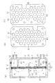
図2(a)〜図6(b)は、電解水生成装置の第1実施形態を示す。
図2(a)および図4に示すように、電解槽1を構成する本体容器2中には電極群10が設けられている。電極群10は、本体容器2内の空間を第1チャンバ31と第2チャンバ32とに区画している。第1チャンバ31側の本体容器2の下部には、水を電解槽1に圧送する導入部21が配設されている。第1チャンバ31側の本体容器2の上部には、生成された電解水を電解槽1から導出する導出部22が配設されている。
【0033】
前記電極群10は、第1,第2および第3電極板11,12,13を含む第1の電極対11,12と第2の電極対12,13とからなる。第1,第2および第3電極板11,12,13は概ね鉛直面に沿って配置されている。第1および第3電極板11,13は、所定の間隙Δを設けて第2電極板12の2つの面に対して対面するように配置されている。前記間隙Δは、水が流れる流路6を定義している。第1,第2および第3電極板11,12,13は、それぞれ絶縁ワッシャ50を介して、絶縁組立ボルト53により締結されている。第1および第3電極板11,13は、ワッシャ51を介してネジ55により第1電極端子71に固定されている。第2電極板12は、ネジ55により第2電極端子72に固定されている。なお、ワッシャ51およびネジ55は導体で形成されている。
【0034】
図3(b)に示すように、第1電極板11には多数(たとえば、10個以上)の貫通孔61が形成されている。第3電極板13は、第1電極板11と同様の形状である。図3(c)に示すように、第2電極板12には多数(たとえば、10個以上)の貫通孔62が形成されている。図2(b)に示すように、第1および第3電極板11,13の貫通孔61と第2電極板の貫通孔62は、互いに位相が左右にズレている。
【0035】
図3(a)に示すように、第1チャンバ31における導入部21の上部と導出部22の下部との間には、第1チャンバ31を上下に区画する第1および第3規制板(規制部材)41,43が配設されている。第2チャンバ32内には、第2チャンバを上下に区画する第2規制板42が配設されている。第2規制板42は第1規制板41よりも上方の位置に配置されている。第3規制板43は第2規制板42よりも上方の位置に配置されている。各規制板41,42,43がこのように配置されていることにより、各規制板41,42,43が電解槽1内に迷路構造を形成している。各規制板41,42,43は、導入部21から電解槽1に導入され導出部22から導出されるまでの水の流れFが前記迷路に沿うように規制するものである。すなわち、水が各電極板11,12,13の貫通孔61,62を通って電極群10を複数回横切りながらS字状に上昇するように規制する。各規制板41,42,43の下面は電極群10に向って上方に傾斜している。この傾斜により、電気分解されて発生した酸素ガスや水素ガス等の気泡が水と共に電極群10に向って流れる。そのため、前記気泡は各規制板41,42,43の下面に溜まらなくなる。
【0036】
前記各規制板41,42,43は、各チャンバ31,32内の水が上方に向って流れるのを抑制する。すなわち、導入部21から第3電極板13の貫通孔61に向って吐出された水は、第3、第2および第1電極板13,12,11の貫通孔61,62を通ることで電極群10を第1の方向D1に横切って第2チャンバ32内に導入される。第2チャンバ32内に導入された水は、第1、第2および第3電極板11,12,13の貫通孔61,62を通ることで電極群10を第2の方向D2に横切って第1チャンバ31内における第1規制板41よりも上方の空間に流れ込む。第1規制板41よりも上方の空間に流れ込んだ水は、再び電極群10を第1の方向D1に横切って第2チャンバ32内における第2規制板42よりも上方の空間に流れ込む。第2規制板42よりも上方に流れ込んだ水は、再び電極群10を第2の方向D2に横切って第1チャンバ31内における第3規制板43の上方の空間に流れ込み、導出部22から導出される。
【0037】
今、電解槽1の中に水が満たされ、導出部22から水が吐出されている状態で、各電極板11,12,13に電圧が印加されると、水は電気分解されて各電極11,12,13から酸素ガスおよび水素ガス等が発生する。これらのガスは水と共に、各電極板11,12,13の多数の貫通孔61,62や流路6を通って電極群10を複数回横切りながら上昇し、生成された電解水と共に導出部22を通して導出される。
【0038】
つぎに、オゾンO3 および残留塩素ClO- の発生のメカニズムについて説明する。
導入部21から電解槽1内に導入された水は、電極群10で電気分解され、発生した酸素分子O2 等と共に第2チャンバ32に流れ込む。この際、第1および第3電極板11,13の貫通孔61と第2電極板12の貫通孔62の位相がズレているので、水が電極群10を通過する際に、水と共に、酸素分子O2 が流路6に沿って上方に流れる。この流路6に沿って上昇した酸素分子O2 は高い電位の電極板上に発生した酸素原子Oと結合してオゾンO3 を発生する。また、水は複数回にわたって電極群10を横切るように流れるので、電極群10を横切る際に、前述と同様に酸素分子O2 が流路6に沿って上方に流れ、酸素分子O2 と酸素原子Oとが結合してオゾンO3 を発生する。このように、導入部21から導入された水が電極群10を複数回横切ることにより、電気分解によって発生した酸素分子O2 と酸素原子Oとの結合確率が高まるので、オゾンO3 の発生確率が高くなる。また、電極対および電極群10の全ての電極板11〜13に、多数の貫通孔を設けたので、電極板11〜13の表面に沿って流れる水の量が多くなる。そのため、前記オゾンO3 の発生する確率が高くなる。一方、残留塩素ClO- に関しても、塩素イオンCl- を含んだ水が複数回にわたって電極群10を横切るように流れることで、塩素イオンCl- が電極板11〜13に接触する確率が高まる。これにより、残留塩素ClO- の発生確率も高まる。
【0039】
各電極板11,12,13の貫通孔61,62は、水が電極群10を横切り、更に、流路6に液体が流入し易くすると共に、発生した水素ガスや酸素ガスを電極の間隙Δから逃がすためのものである。したがって、貫通孔61,62の形状は、丸穴、長穴、十字穴、角穴の他にスリット状の長穴などでもよく、たとえば各電極板11,12,13としてはエキスパンドメタルを使用しても良い。
【0040】
図5は、電気回路のブロック図の一例を示す。
この図に示すように、第1,第2および第3電極板11,12,13には、切替回路50を介して、直流電源51が接続されている。前記切替回路50には制御回路(マイコン)52が接続されている。該制御回路52はタイマ53を内蔵していると共に、流量検知回路54および設定器55に接続されている。
【0041】
前記設定器55は、各電極板11,12,13の間に流れる電流の向きを切り替える時間Tを入力するためのものであり、当該設定器55から設定された切替時間Tは制御回路52に記憶される。前記流量検知回路54は、電解槽1から流出する水の流量(電解槽1内に流入する水の流量)を検出するためのセンサ56を含む。前記センサ56が所定の流量よりも多い(または、少ない)流量を検出した時には、流量検知回路54は、設定された切替時間Tよりも短い(または、長い)切替時間に補正するための信号を制御回路52に出力する。流量がゼロの時には、流量検知回路54は、各電極板11,12,13へ流れる電流を遮断するための信号を制御回路52に出力する。
【0042】
つぎに、各電極11〜13の電位および切り替えについて説明する。
図6(a),(b)において、電解槽1を構成する本体容器2は、接地されており、常時接地電位に設定されている。図6(a)の第1の状態では、第1,第2および第3電極板11,12,13の電位は、それぞれ、+V,GND(接地電位),−V(接地電位よりも低い電位)に設定されている。一方、制御回路52(図5)により、所定時間後に、切替回路50の切替スイッチ50a〜50dを切り替えると、図6(b)の第2の状態となる。該第2の状態では、第1,第2および第3電極板11,12,13の電位は、それぞれ、−V,GND,+Vに設定される。したがって、電極群10における第1の電極対11,12の電位差は、+Vから−Vに切り替わり、一方、第2の電極対12,13の電位差は、−Vから+Vに切り替わる。
【0043】
なお、本実施形態に示すように、各電極板11〜13の全ての電位を切り替えなくても、各電極対の電位差を切り替えて、電流の流れる向きを切り替えることができる。
【0044】
本実施形態において、本体容器2の内面2aに対向する第1および第3電極板11,13の電位は、それぞれ、本体容器2の接地電気GNDに対して+Vおよび−Vに切り替えられる。したがって、各電極板11〜13にスケールが付着するのを防止し得るだけでなく、第1および第3電極板11,13に対する本体容器2の相対電位が交番するので、本体容器2の内面2aにスケールが付着しても、当該スケールが溶解する。
【0045】
つぎに、電極群10および切替回路50の他の例について説明する。なお、以下に説明する電極群10の各電極板11〜15の構造は、たとえば多数の貫通孔を有しているなど前記第1実施形態の電極板と同様な構成であり、その説明は省略する。
【0046】
図7(a)〜7(d)の実施形態は、2枚の電極板11,12で電極群10を構成している。この実施形態では各電極板11,12の電位が+V→GND→GND→−V→+Vの順に切り替えられて、電極対11,12の間の電位差が+Vまたは−Vに切り替えられる。
なお、本実施形態では、各電極板11,12の電位を交互に+Vと−Vに取り替えてもよいが、この場合、本体容器2の内面2aにスケールが付着する。
【0047】
図8(a),(b)の実施形態は、5枚の電極板11〜15で電極群10を構成している。この実施形態では、第1、第3および第5電極板11,13,15の電位が+V,−Vに交互に切り替えられて、電極対11,12、電極対12,13、電極対13,14および電極対14,15の電位差が交番するように切り替えられる。なお、第2および第4電極板12,14および本体容器2の電位は常時GNDに設定されている。
【0048】
図9(a),(b)の実施形態は、5枚の電極板11〜15で電極群10を構成している。図9(a)の第1の状態では,第1,第2,第3,第4および第5の電極板11,12,13,14,15の電位がそれぞれ、+V,+V/2,GND,−V/2,−Vに設定されている。図9(b)の第2の状態では、前記各電極板11〜15の極性が正負反転される。なお、第3電極板13および本体容器2の電位は常時GNDに設定されている。
本実施形態において、第2(第4)電極板12(14)は、直流電源51に接続されておらず、第1および第3(第3および第5)11,13(13,15)の間に配置されているので、これらの電極板の間の電位となる。
【0049】
本発明者は、各電極対の電位を10秒毎に切り替えて、規制板を設けない場合と規制板を設けた場合について、オゾン濃度と残留塩素濃度の測定を行った。その結果、規制板を設けない場合では、オゾン濃度は1.0mg/l 、残留塩素濃度は5.4mg/l であった。それに対し、規制板を設けた場合では、オゾン濃度は1.7mg/l 、残留塩素濃度は7.0mg/l であった。すなわち、規制板を設けて、水を何度も電極群10に向かわせることにより、オゾン濃度および残留塩素濃度が大きく増加することが確認できた。
【0050】
本発明においては、図1(b)に示すように、3枚以上の電極板(たとえば5枚の電極板11〜15)で電極群10を構成し、該電極群10の下方に導入部21を設けて、電極群10の下端から上方に向って水を導入してもよい。この場合、水は矢印Fで示すように、複数の電極板12,11の貫通孔62,61を通って電極対12,11を第2の方向D2に横切りながら上昇し、あるいは、複数の別の電極板14,15の貫通孔62,61を通って電極対14,15を第1の方向D1に横切りながら上昇する。なお、この場合、互いに隣接して対向する2枚の電極板にとって、他の電極板は規制手段として作用する。
【0051】
なお、各電極板の周縁と本体容器との間に隙間を設けてもよい。
【0052】
【発明の効果】
以上説明したように、本発明の電解水生成装置は、強力に水を電気分解する装置であり、水のクラスターを破壊し、水の表面張力を下げ、界面活性効果を高める。更に、水素ガスや酸素ガス等の微細な気泡を豊富に含んだ電解水を生成するため、界面活性効果に加えてキャビテーションの作用も加わり、洗剤を使用しなくても優れた洗浄用水となる。
また、各電極板に貫通孔を設けたので、液体が前記貫通孔を通って電極対を横切りながら上昇するので、気泡が液体と共に貫通孔を容易に通過する。しかも、貫通孔の付近では化学反応が生じ易いので、電解水中のオゾンや残留塩素の濃度が高くなる。
特に、液体の流れが電極対の各貫通孔を通って電極対を横切りながら、S字状および/または逆S字状に上昇するように、前記液体の流れ方向を規制すれば、電解水を含んだ液体が何度も電極対の表面に接触するから、オゾンや残留塩素の濃度が高まる。
【0053】
また、電解水生成装置の電極印加電圧を所定の短い時間の間隔で切り替えることで水中オゾン濃度等を更に高めることができ、洗浄効果に加えて殺菌効果も併せ持った殺菌洗浄水となる。
【0054】
なお、前記電解槽を構成する本体容器が接地電位に設定され、前記電極対のうち第1電極板が接地電位よりも高い高電位となる第1の状態と、前記第1電極板が接地電位よりも低い低電位となる第2の状態とに切り替えられるようにすれば、本体容器の内面にスケールが付着しても、当該スケールが液中に溶け出す。
【図面の簡単な説明】
【図1】(a)は本発明の電解水生成装置の一態様を示す概略正面図、(b)は同電解水生成装置の要部の構成の他の例を示す正面図である。
【図2】(a)は本発明の第1実施形態にかかる電解水生成装置を示し、図2(b)のA−A線で断面した断面図、(b)は電極群を示す側面図である。
【図3】(a)は第1実施形態にかかる電解水生成装置を示し、図2(b)のC−C線で断面した断面図、(b)は第1実施形態の第1電極板を示す側面図、(c)は同第2電極板を示す側面図である。
【図4】同電極群および規制板を示す斜視図である。
【図5】第1実施形態の電解水生成装置にかかる概略構成図である。
【図6】同電極群および切替回路を示し、(a),(b)は、それぞれ、電位の切替の状態を示す概略構成図である。
【図7】電極群および切替回路の他の例を示し、(a)〜(d)は、それぞれ、電位の切替の状態を示す概略構成図である。
【図8】電極群および切替回路の更に他の例を示し、(a),(b)は、それぞれ、電位の切替の状態を示す概略構成図である。
【図9】電極群および切替回路の更に他の例を示し、(a),(b)は、それぞれ、電位の切替の状態を示す概略構成図である。
【符号の説明】
1:電解槽
2:本体容器
10:電極群
11,12,13:第1,第2および第3電極板(板状電極)
11,12:第1電極対
12,13:第2電極対
21:導入部
22:導出部
31:第1チャンバ
32:第2チャンバ
40:規制板(規制手段)
41,42,43:第1,第2および第3規制板(規制部材)
51:直流電源
52:制御回路
61,62:貫通孔
D1:第1の方向
D2:第2の方向
F:流れ方向[0001]
BACKGROUND OF THE INVENTION
The present invention relates to the generation of electrolyzed water having a cleaning effect and a sterilizing effect.
[0002]
[Prior art]
In recent years, electrolytic water has attracted attention as washing water.
For example, in the generation apparatus disclosed in Japanese Patent Laid-Open No. 2000-317414, a negative electrode plate having a large number of holes and a positive electrode plate without holes are opposed to each other, and water flows along both electrode plates. Thereby, electrolyzed water having a cleaning effect is generated.
[0003]
In the apparatus of JP-A-6-277385, a long labyrinth-shaped flow path is formed between a positive electrode and a negative electrode, and water is allowed to flow along the flow path. Thereby, while producing electrolyzed water, ozone is generated and electrolyzed water with a bactericidal effect is produced.
[0004]
[Problems to be solved by the invention]
However, in these prior arts, since ozone is accidentally generated, it is difficult to increase the concentration of ozone.
Accordingly, a main object of the present invention is to provide an apparatus that generates electrolyzed water having a cleaning effect and a high ozone concentration.
[0005]
In the apparatus disclosed in Japanese Patent Laid-Open No. 62-227494, three plate electrodes having a large number of through holes are arranged along a horizontal plane in a state where they are separated from each other in the vertical direction, and a liquid flows from the bottom to the top. In this apparatus, since bubbles are accumulated on the lower surface of the plate-like electrode, not only the efficiency is low, but also small bubbles of oxygen hardly rise upward, so that almost no ozone is generated.
[0006]
In the apparatus disclosed in Japanese Patent Laid-Open No. 56-786769, a spacer is interposed between an anode and a cathode made of a metal mesh, and a liquid is pumped in a lateral direction perpendicular to the metal mesh. In this apparatus, since the liquid flows in a direction perpendicular to the metal net, it is necessary to provide a large number of metal nets in order to increase the ozone concentration in the liquid. This not only increases the size of the apparatus, but also complicates the structure for fixing the metal net, which increases costs.
Accordingly, another object of the present invention is to reduce the size and cost of the electrolyzed water generator.
[0007]
Incidentally, Japanese Patent Application Laid-Open No. 11-216483 discloses a washing machine provided with an electrolyzed water generating unit. This washing machine periodically reverses the polarity of the two electrodes to prevent unidirectional wear of the electrodes. However, no disclosure is made regarding the time for reversing the polarity, and the ozone generation efficiency cannot be increased by switching the polarity.
[0008]
[Means for Solving the Problems]
To achieve the above purpose,Main departureLightSome aspects of1 will be described with reference to FIG.
BookAspectIs an electrolyzed water generating device that generates electrolyzed water from a liquid, and includes an
[0009]
In the present invention, the “plate electrode” means that a metal net is included in addition to an electrode plate in which a large number of through holes are formed in a plate-like conductor such as a metal plate.
[0010]
Water molecules are said to behave like macromolecules by forming clusters (an aggregate of molecules formed by aggregation of multiple molecules) by hydrogen bonding. However, when water is electrolyzed, water molecules generate oxygen gas, hydrogen gas, and new water molecules by the chemical reactions shown in the following equations (1), (2), and (3).
[0011]
H2O → H++ OH- … (1)
2H++ 2e-→ H2 … (2)
4OH-→ 4e-+ O2+ 2H2O ... (3)
[0012]
By performing such a chemical change, the cluster is destroyed. Thereby, the surface tension of water is reduced, the surface-active effect is increased, and the permeability to the dirt substance is increased. Furthermore, since the generated electrolyzed water contains abundant fine bubbles such as hydrogen gas and oxygen gas, cavitation (the generated bubbles become nuclei and innumerable microcavities close to vacuum are generated. The action of generating an impact force when this collapses) makes it easy to peel off the adhered substance that causes the dirt from the object to be cleaned.
It has been confirmed that the surface tension of tap water can be reduced from 0.0722 N / m to about 0.0716 N / m by electrolysis.
[0013]
In the present invention, water or an aqueous solution is used as raw water (liquid). Here, in order to obtain the chemical reactions of the above formulas (1) to (3), the raw water needs to have conductivity, and therefore, the raw water itself needs to contain ions. Distilled water) or ion-exchanged water can be used, but generally tap water or well water can be used. Further, an aqueous solution to which sodium chloride or citric acid is added can also be adopted as the aqueous solution.
[0014]
The amount of water electrolysis is proportional to the value of the current flowing through the electrode pairs 11 and 12. Therefore, in order to perform strong electrolysis, it is necessary to increase the current value as much as possible. Therefore, in the present invention, the gap Δ between the
[0015]
The
The “face-to-face” means that no diaphragm is provided between the two
[0016]
On the other hand, by reducing the gap Δ between the
[0017]
When water enters the
[0018]
When water is electrolyzed, fine bubbles of hydrogen gas and oxygen gas are generated. The fine bubbles generated in this manner serve as nuclei, generating innumerable microcavities close to vacuum, and an impact force is generated when the microcavities collapse. This phenomenon is called cavitation, and the energy when the bubbles collapse is effectively used as a cleaning action.
In addition, it is preferable that the ozone concentration in water required for disinfection is 1 mg / L or more.
[0019]
Further, when water is electrolyzed by the plurality of
[0020]
For example, when the potential of the
OH + OH → O + H2O ... (4)
O + O → O2 …(Five)
[0021]
In other words, oxygen molecules (oxygen gas) are generated as shown in the chemical reaction formula (3). Oxygen molecules O generated on the surface of the
[0022]
In such a state, when the potentials of the
O + O2→ OThree … (6)
That is, by switching the polarities of the
[0023]
In general tap water, chloride ion Cl at a concentration of about 10 to 20 mg / liter-It is included. When such tap water is electrolyzed, chlorine ions Cl are obtained by the chemical reaction shown in the following equation (11).-Emits electrons to the electrode plate, and chlorine gas Cl in water2Is generated.
2Cl-→ 2e-+ Cl2 … (11)
Chlorine gas generated in water reacts easily with hydroxyl ions in water by a chemical reaction shown in the following formula (12), and newly generates chlorine ions and residual chlorine ClO.-And water H2O is generated.
Cl2+ 2OH-→ Cl-+ ClO-+ H2O ... (12)
Residual chlorine ClO generated here-Is a substance that is not very strong as an oxidant, but has a bleaching action and a bactericidal action.
Although ozone has a strong sterilizing power immediately after generation, it is said that the lifetime in water is several seconds to several tens of minutes. On the other hand, although residual chlorine has a weak sterilizing power, it can maintain a sterilizing effect for a long time.
[0024]
By electrolyzing tap water having chlorine ions with the above-described apparatus, ozone and residual chlorine as described above can be generated simultaneously. As a result, the generated electrolyzed water exhibits a strong sterilizing power by ozone immediately after electrolyzing tap water, and maintains a corresponding sterilizing power by residual chlorine after a long time.
When the bactericidal effect on various bacteria was measured, the bactericidal effect did not deteriorate even with water stored for 24 hours as well as water immediately after electrolysis.
[0025]
By the way, bookAspectIn this case, the potential difference between the electrode pairs 11 and 12 is switched to alternate the potential difference.May. However, if the liquid rises while passing through the electrode pairs 11 and 12 a plurality of times through the through
[0026]
BookAspectIn this case, switching the potential difference between the electrode pairs 11 and 12 does not only mean switching the potentials of the first and
[0027]
By the way, as described above, ozone is generated even when water is electrolyzed without switching the potential difference applied to the
On the contrary, if the time ΔT until the switching is short to some extent, the polarity is switched before the scale is deposited on the
[0028]
In some examples of this aspectIs an electrolyzed water generating device that generates electrolyzed water from a liquid, and includes an
[0029]
In the present invention, generally, the portions provided with the through
Condition (1) The phases of the through
Condition (2) The through
Condition (3) The pitches of the through
[0030]
That is, when the through
[0031]
BookExampleIn order to remove the scale, the potential difference between the electrode pairs 11 and 12 is switched automatically or manually after a certain period of time (about 15 minutes) of operation of the electrolyzed water generator or when it is not in operation. You may make it alternate. Further, the
[0032]
DETAILED DESCRIPTION OF THE INVENTION
Hereinafter, embodiments of the present invention will be described with reference to the drawings.
Fig.2 (a)-FIG.6 (b) show 1st Embodiment of an electrolyzed water generating apparatus.
As shown in FIG. 2A and FIG. 4, an
[0033]
The
[0034]
As shown in FIG. 3B, a large number (for example, 10 or more) of through
[0035]
As shown in FIG. 3A, between the upper part of the
[0036]
The restricting
[0037]
Now, when a voltage is applied to each of the
[0038]
Next, Ozone OThreeAnd residual chlorine ClO-The mechanism of occurrence of this will be described.
The water introduced into the
[0039]
The through holes 61 and 62 of each of the
[0040]
FIG. 5 shows an example of a block diagram of an electric circuit.
As shown in this figure, a
[0041]
The
[0042]
Next, the potential and switching of the
6 (a) and 6 (b), the
[0043]
In addition, as shown in this embodiment, even if it does not switch all the electric potentials of each electrode plates 11-13, the electric potential difference of each electrode pair can be switched and the direction through which an electric current can be switched.
[0044]
In the present embodiment, the potentials of the first and
[0045]
Next, another example of the
[0046]
In the embodiment of FIGS. 7A to 7D, the
In the present embodiment, the potentials of the
[0047]
In the embodiment of FIGS. 8A and 8B, the
[0048]
In the embodiment of FIGS. 9A and 9B, the
In the present embodiment, the second (fourth) electrode plate 12 (14) is not connected to the
[0049]
The inventor switches the potential of each electrode pair every 10 seconds, and measures the ozone concentration and the residual chlorine concentration when the restriction plate is not provided and when the restriction plate is provided. As a result, the ozone concentration was 1.0 mg / l and the residual chlorine concentration was 5.4 mg / l without the restriction plate. On the other hand, when the restriction plate was provided, the ozone concentration was 1.7 mg / l and the residual chlorine concentration was 7.0 mg / l. That is, it was confirmed that the ozone concentration and the residual chlorine concentration were greatly increased by providing a regulating plate and directing water to the
[0050]
In the present invention, as shown in FIG. 1B, the
[0051]
A gap may be provided between the periphery of each electrode plate and the main body container.
[0052]
【The invention's effect】
As described above, the electrolyzed water generator of the present invention is a device that strongly electrolyzes water, destroys water clusters, lowers the surface tension of water, and enhances the surface activity effect. Furthermore, since electrolyzed water containing abundant fine bubbles such as hydrogen gas and oxygen gas is generated, the action of cavitation is added in addition to the surface active effect, and the water becomes excellent cleaning water without using a detergent.
Since each electrode plate is provided with a through-hole, the liquid rises while passing through the through-hole and across the electrode pair, so that bubbles easily pass through the through-hole together with the liquid. Moreover, since chemical reactions are likely to occur in the vicinity of the through holes, the concentrations of ozone and residual chlorine in the electrolytic water are increased.
In particular, if the flow direction of the liquid is regulated so that the flow of the liquid rises in an S shape and / or an inverted S shape while traversing the electrode pair through each through hole of the electrode pair, the electrolyzed water is Since the contained liquid contacts the surface of the electrode pair many times, the concentration of ozone and residual chlorine increases.
[0053]
Further, by switching the electrode application voltage of the electrolyzed water generating device at predetermined short time intervals, the ozone concentration in water can be further increased, and the sterilized cleaning water has a sterilizing effect in addition to the cleaning effect.
[0054]
In addition,A main body container constituting the electrolytic cell is set to a ground potential, and a first state in which the first electrode plate of the electrode pair is at a higher potential than the ground potential, and the first electrode plate is lower than the ground potential. If you can switch to the second state where the potential is low and lowEven if the scale adheres to the inner surface of the main body container, the scale dissolves into the liquid.
[Brief description of the drawings]
FIG. 1 (a) is a schematic front view showing one embodiment of an electrolyzed water generating device of the present invention, and FIG. 1 (b) is a front view showing another example of the configuration of the main part of the electrolyzed water generating device.
2A shows the electrolyzed water generating apparatus according to the first embodiment of the present invention, and is a cross-sectional view taken along line AA in FIG. 2B, and FIG. 2B is a side view showing an electrode group; It is.
3A shows the electrolyzed water generating apparatus according to the first embodiment, and is a cross-sectional view taken along line CC in FIG. 2B. FIG. 3B is a first electrode plate according to the first embodiment. (C) is a side view which shows the 2nd electrode plate.
FIG. 4 is a perspective view showing the same electrode group and a regulating plate.
FIG. 5 is a schematic configuration diagram according to the electrolyzed water generating apparatus of the first embodiment.
FIGS. 6A and 6B show the same electrode group and a switching circuit, and FIGS. 6A and 6B are schematic configuration diagrams showing states of potential switching.
FIG. 7 shows another example of an electrode group and a switching circuit, and (a) to (d) are schematic configuration diagrams showing states of potential switching.
FIGS. 8A and 8B show still another example of an electrode group and a switching circuit, and FIGS. 8A and 8B are schematic configuration diagrams showing states of potential switching, respectively. FIGS.
FIGS. 9A and 9B show still another example of an electrode group and a switching circuit, and FIGS. 9A and 9B are schematic configuration diagrams showing states of potential switching, respectively. FIGS.
[Explanation of symbols]
1: Electrolyzer
2: Body container
10: Electrode group
11, 12, 13: first, second and third electrode plates (plate electrodes)
11, 12: First electrode pair
12, 13: Second electrode pair
21: Introduction
22: Deriving part
31: First chamber
32: Second chamber
40: Restriction plate (regulation means)
41, 42, 43: first, second and third regulating plates (regulating members)
51: DC power supply
52: Control circuit
61, 62: Through-hole
D1: First direction
D2: Second direction
F: Flow direction
Claims (4)
電解槽と、
液体を前記電解槽に圧送する導入部と、
前記電解槽内に概ね鉛直面に沿って、かつ、隔膜が間に設けられていない状態で互いに対面するように、かつ、間隔が0.5mm〜3.0mmとなるように配置された少なくとも第1および第2の板状電極を含む電極対と、
前記各板状電極の間に直流電圧を印加する直流電源と、
前記液体を電解槽内で電気分解することにより生成された電解水を前記電解槽から導出する導出部と、
互いに電位差のある前記2枚の板状電極の間に形成された流路とを備え、
前記導入部は前記電極対の間の前記流路の下端から上方に向かって液体を前記流路に導入するように設けられ、
前記導出部は前記電解槽の上部に設けられ、
前記導入部から前記流路に導入され前記導出部から導出されるまでの液体が、前記板状電極を横切りながら上昇することが可能なように、前記2枚の板状電極に各々、複数の貫通孔が形成されていると共に、前記板状電極の貫通孔を横切った液体が前記流路に再び向かいながら上昇することが可能なように前記板状電極の少なくとも一方に規制板が近接して対向配置されている電解水生成装置。An electrolyzed water generating device for generating electrolyzed water from a liquid,
An electrolytic cell;
An introduction section for pumping liquid to the electrolytic cell;
In the electrolytic cell, at least the first and the second electrodes are disposed so as to face each other along a substantially vertical plane, with no diaphragm provided therebetween, and at a distance of 0.5 mm to 3.0 mm . An electrode pair including first and second plate electrodes;
A DC power source for applying a DC voltage between the plate electrodes;
A lead-out unit for leading out the electrolyzed water generated by electrolyzing the liquid in the electrolytic cell from the electrolytic cell;
A flow path formed between the two plate electrodes having a potential difference from each other,
The introduction part is provided so as to introduce liquid into the flow path upward from the lower end of the flow path between the electrode pair,
The lead-out part is provided in the upper part of the electrolytic cell,
Each of the two plate electrodes has a plurality of liquids so that the liquid introduced from the introduction portion into the flow path and led out from the lead-out portion can rise while crossing the plate electrodes. A restricting plate is close to at least one of the plate-like electrodes so that a liquid passing through the through-hole of the plate-like electrode can rise while again facing the flow path. An electrolyzed water generating device arranged oppositely .
電解槽と、
液体を前記電解槽に圧送する導入部と、
前記電解槽内に概ね鉛直面に沿って配置された少なくとも第1、第2および第3の板状電極を含む電極群と、
前記各板状電極の間に直流電圧を印加する直流電源と、
前記液体を電解槽内で電気分解することにより生成された電解水を前記電解槽から導出する導出部とを備え、
前記導入部から前記流路に導入され前記導出部から導出されるまでの液体が、前記複数の板状電極を横切りながら上昇することが可能なように、各板状電極に各々、複数の貫通孔が形成され、
前記第1および第3電極板は、所定の間隙を設けて第2電極板の2つの面に対して隔膜が間に設けられていない状態で対面するように配置され、前記間隙は液体が流れる流路を定義しており、
前記間隔が0.5mm〜3.0mmに設定され、
前記液体が前記流路を前記電極板に沿って上方に向って流れるように前記導入部から前記流路に液体が導入される電解水生成装置。An electrolyzed water generating device for generating electrolyzed water from a liquid,
An electrolytic cell;
An introduction section for pumping liquid to the electrolytic cell;
An electrode group including at least first, second and third plate-like electrodes disposed substantially along a vertical plane in the electrolytic cell;
A DC power source for applying a DC voltage between the plate electrodes;
A deriving unit for deriving electrolyzed water generated by electrolyzing the liquid in the electrolytic cell from the electrolytic cell;
Each plate electrode has a plurality of penetrating holes so that the liquid introduced from the introduction part to the flow path and led out from the lead-out part can rise while crossing the plurality of plate electrodes. Holes are formed,
The first and third electrode plates are arranged so as to face each other with a predetermined gap and no diaphragm between the two surfaces of the second electrode plate, and liquid flows through the gap. Defines the flow path,
The interval is set to 0.5 mm to 3.0 mm,
An electrolyzed water generating apparatus in which a liquid is introduced into the flow path from the introduction portion so that the liquid flows upward along the electrode plate along the flow path .
Priority Applications (1)
| Application Number | Priority Date | Filing Date | Title |
|---|---|---|---|
| JP2002046356A JP3805696B2 (en) | 2002-02-22 | 2002-02-22 | Electrolyzed water generator |
Applications Claiming Priority (1)
| Application Number | Priority Date | Filing Date | Title |
|---|---|---|---|
| JP2002046356A JP3805696B2 (en) | 2002-02-22 | 2002-02-22 | Electrolyzed water generator |
Publications (3)
| Publication Number | Publication Date |
|---|---|
| JP2003245671A JP2003245671A (en) | 2003-09-02 |
| JP2003245671A5 JP2003245671A5 (en) | 2006-03-16 |
| JP3805696B2 true JP3805696B2 (en) | 2006-08-02 |
Family
ID=28659797
Family Applications (1)
| Application Number | Title | Priority Date | Filing Date |
|---|---|---|---|
| JP2002046356A Expired - Fee Related JP3805696B2 (en) | 2002-02-22 | 2002-02-22 | Electrolyzed water generator |
Country Status (1)
| Country | Link |
|---|---|
| JP (1) | JP3805696B2 (en) |
Families Citing this family (5)
| Publication number | Priority date | Publication date | Assignee | Title |
|---|---|---|---|---|
| JP5102271B2 (en) * | 2005-12-27 | 2012-12-19 | 株式会社富永製作所 | Method for washing and sterilizing eggshell |
| JP4652318B2 (en) * | 2005-12-27 | 2011-03-16 | 株式会社富永製作所 | Electrolyzed water generator and sterilization method using electrolyzed water |
| JP4757783B2 (en) * | 2005-12-27 | 2011-08-24 | 株式会社富永製作所 | How to wash and sterilize eggshell |
| JP6106396B2 (en) * | 2012-01-10 | 2017-03-29 | 石福金属興業株式会社 | Sterilization water generator |
| CN114150332A (en) * | 2021-12-15 | 2022-03-08 | 珠海格力电器股份有限公司 | Disinfectant liquid manufacturing apparatus and control method thereof |
-
2002
- 2002-02-22 JP JP2002046356A patent/JP3805696B2/en not_active Expired - Fee Related
Also Published As
| Publication number | Publication date |
|---|---|
| JP2003245671A (en) | 2003-09-02 |
Similar Documents
| Publication | Publication Date | Title |
|---|---|---|
| JP3805621B2 (en) | Electrolyzed water generator | |
| JP2002079248A (en) | Electrolytic water making apparatus | |
| JP2012081448A (en) | Sterilized water making apparatus, and method for making sterilized water | |
| JP3805696B2 (en) | Electrolyzed water generator | |
| KR20060105238A (en) | Apparatus for producing sterilizing and oxidizing water by electrolysis cell used overpotential electrode | |
| JP2006346650A (en) | Apparatus and method for producing alkali sterilization water | |
| KR100841102B1 (en) | An electrolytic water creating device | |
| JP2004143481A (en) | Electrode for electrolysis, and electrolytic device | |
| JP4056623B2 (en) | Electrolytic tank of electrolysis neutral water generator | |
| KR20080040659A (en) | Induction catalyst and electrolysis system | |
| JP4838705B2 (en) | Ozone water generator | |
| KR100603536B1 (en) | Electrolysis having a mesh type electrode | |
| JP6000673B2 (en) | Ozone water generator refresh cleaning method | |
| KR102250773B1 (en) | System for generating oxidizers | |
| CN210341086U (en) | Sodium hypochlorite generator electrolytic cell with store up dirty function | |
| KR100651654B1 (en) | A water purifier using an electrolysis | |
| JPH10328667A (en) | Method for making sterilized water | |
| JP3550858B2 (en) | Electrolysis device and ion water generator | |
| US4436605A (en) | Bipolar electrode electrolysis apparatus | |
| KR200371538Y1 (en) | Catridge-type device for producing hydrogen-abundant water | |
| JP3770530B2 (en) | Electrolyzer for hypochlorite production | |
| EP1226094B1 (en) | Device for electrolysis | |
| KR20070030866A (en) | Electrolytic water create system | |
| JP3568290B2 (en) | Electrolyzed water generator | |
| CN212375401U (en) | Space sterilizer capable of generating effective chlorine through electrolysis without cavity division |
Legal Events
| Date | Code | Title | Description |
|---|---|---|---|
| A621 | Written request for application examination |
Free format text: JAPANESE INTERMEDIATE CODE: A621 Effective date: 20040602 |
|
| A521 | Written amendment |
Free format text: JAPANESE INTERMEDIATE CODE: A523 Effective date: 20051206 |
|
| A977 | Report on retrieval |
Free format text: JAPANESE INTERMEDIATE CODE: A971007 Effective date: 20051216 |
|
| A521 | Written amendment |
Free format text: JAPANESE INTERMEDIATE CODE: A523 Effective date: 20060127 |
|
| A131 | Notification of reasons for refusal |
Free format text: JAPANESE INTERMEDIATE CODE: A131 Effective date: 20060214 |
|
| A521 | Written amendment |
Free format text: JAPANESE INTERMEDIATE CODE: A523 Effective date: 20060330 |
|
| TRDD | Decision of grant or rejection written | ||
| A01 | Written decision to grant a patent or to grant a registration (utility model) |
Free format text: JAPANESE INTERMEDIATE CODE: A01 Effective date: 20060509 |
|
| A61 | First payment of annual fees (during grant procedure) |
Free format text: JAPANESE INTERMEDIATE CODE: A61 Effective date: 20060510 |
|
| R150 | Certificate of patent or registration of utility model |
Free format text: JAPANESE INTERMEDIATE CODE: R150 |
|
| FPAY | Renewal fee payment (event date is renewal date of database) |
Free format text: PAYMENT UNTIL: 20100519 Year of fee payment: 4 |
|
| FPAY | Renewal fee payment (event date is renewal date of database) |
Free format text: PAYMENT UNTIL: 20110519 Year of fee payment: 5 |
|
| FPAY | Renewal fee payment (event date is renewal date of database) |
Free format text: PAYMENT UNTIL: 20120519 Year of fee payment: 6 |
|
| FPAY | Renewal fee payment (event date is renewal date of database) |
Free format text: PAYMENT UNTIL: 20130519 Year of fee payment: 7 |
|
| LAPS | Cancellation because of no payment of annual fees |