JP3804883B2 - Concrete high structure construction apparatus and concrete oblique column construction method - Google Patents
Concrete high structure construction apparatus and concrete oblique column construction method Download PDFInfo
- Publication number
- JP3804883B2 JP3804883B2 JP16343997A JP16343997A JP3804883B2 JP 3804883 B2 JP3804883 B2 JP 3804883B2 JP 16343997 A JP16343997 A JP 16343997A JP 16343997 A JP16343997 A JP 16343997A JP 3804883 B2 JP3804883 B2 JP 3804883B2
- Authority
- JP
- Japan
- Prior art keywords
- concrete
- formwork
- supported
- workbench
- frame
- Prior art date
- Legal status (The legal status is an assumption and is not a legal conclusion. Google has not performed a legal analysis and makes no representation as to the accuracy of the status listed.)
- Expired - Fee Related
Links
Images


Landscapes
- Bridges Or Land Bridges (AREA)
- Forms Removed On Construction Sites Or Auxiliary Members Thereof (AREA)
Description
【0001】
【発明の属する技術分野】
本願発明は、コンクリートの高い構造物を構築するために用いられ、作業用の足場、コンクリートを打設するための型枠、およびこれらを支持する支保工等を含むコンクリート高構造物構築装置、およびコンクリートの斜柱を含む高構造物を構築する方法に関する。
【0002】
【従来の技術】
高速道路等の主要道路の整備にともない、山岳部で長大橋梁が構築されることが増加し、谷部に架橋される場合には50m以上の高橋脚となることも多くなっている。このように地表面から高く立ち上げられるコンクリート構造物の構築に際し、従来から広く行われているように構造物の周囲に足場を組み上げて作業を行う場合には、足場を大きな耐力を有するものとする必要があり、多くの費用がかかることとなってしまう。特にコンクリート構造物が斜めに立ち上げられる場合には、足場を斜めになった構造物の下側全域に組み立てる必要があり、仮設費用が多大なものとなる。
【0003】
このため、地表面から組み上げる足場を不要とした工法が提案されており、その一つにジャンピングフォーム工法がある。これは、例えば特公昭63−31629号公報に開示されるような装置を用いるものであり、既に打設され硬化したコンクリートに緊結された支柱を上方に立ち上げ、これに、大型パネル化した型枠・足場等を支持させるものである。そして、上方に打設されたコンクリートが硬化し、充分な強度が得られると、支柱の緊結を一旦解放し、上方のブロックに上昇させて再び緊結する。これにより、型枠・足場はさらに上方のブロックのコンクリート打設位置に据え付けることが可能となり、順次上方にコンクリートを打ちたしてゆくことができる。
【0004】
【発明が解決しようとする課題】
しかしながら、上記のような工法では次のような問題点がある。
支柱を上方へもり換えるために、型枠・足場等を一旦仮支持し、支柱のコンクリート躯体への緊結を解放する手段が必要となる。また、コンクリート躯体に緊結された支柱によって型枠を支持し、所定の位置に据え付けるために、型枠の進退を可能にするジャッキ等が必要となる。したがって、装置が複雑化して製作費が高くなるという問題がある。
さらにコンクリート構造物を斜めに立ち上げようとするときには、型枠・足場等に自重によって支柱に大きな曲げモーメントが作用することになり、充分な安全性を維持することが難しくなる。
【0005】
本願発明は、上記のような問題点に鑑みてなされたものであり、その目的は、簡単な装置でコンクリートの高構造物を構築することができ、さらに構造物が斜めに立ち上げられる場合にも適用できるコンクリート高構造物構築装置を提供すること、およびコンクリートの斜柱を少ない費用で安全に構築することができるコンクリート斜柱の構築方法を提供することである。
【0006】
【課題を解決するための手段】
上記問題点を解決するために、請求項1に記載の発明は、 既に打設されたコンクリート躯体から吊り支持されたレールと、 このレール上に走行可能に支持された第1の作業台と、 前記第1の作業台に支持され、大型パネル化された型枠であって、前記コンクリート躯体の上部に新たなコンクリートを打設するために設けられる第1の型枠と、 前記第1の作業台を、前記コンクリート躯体の側面に対して前進および後退するように駆動する駆動装置と、 前記第1の作業台に支持され、この第1の作業台が駆動される方向と同方向に相対移動が可能に設けられた第2の作業台と、 大型パネル化され、前記第1の型枠と対向して前記第2の作業台上に支持された第2の型枠と、を有するコンクリート高構造物構築装置を提供する。
【0007】
このようなコンクリート高構造物構築装置では、大型パネル化された第1の型枠は、レール上を走行可能な第1の作業台上に支持されており、駆動装置によって第1の作業台をコンクリート躯体の側面に対して前進または後退させることによって、第1の型枠を所定の位置に据え付けられ、または打設されたコンクリートから脱型される。
また、第2の型枠は、上記第1の作業台上に支持された第2の作業台に取り付けられており、第1の作業台と第2の作業台とが相対移動しないように係止した状態で上記駆動装置により第1の作業台を駆動することにより、第2の型枠もコンクリート躯体に対して前進または後退し、所定位置への据え付けまたは打設したコンクリートからの脱型が容易に行われる。
【0008】
なお、コンクリート躯体の両側にある上記第1の型枠を第2の型枠とを脱型するには、それぞれの型枠が反対方向に移動しなければならず、同時に行うことはできないが、第1の作業台と第2の作業台との間の係合を解放しておき、第1の型枠を脱型した後再び双方の作業台を係止し、駆動装置で第1の作業台を駆動することによって第2の型枠の脱型を行うことができる。したがって、二つの大型パネル化した型枠を一基の駆動装置によって所定装置への据え付け、または脱型することが可能となる。
また、第1の型枠を所定位置に据え付けた後に、第2の型枠を移動させるのが工程上望ましい場合等には、第1の作業台または第2の作業台のいずれか一方に固定され、他方を引き寄せる牽引装置を設けてもよい。
【0009】
そして、上記第1の作業台はコンクリート躯体から吊り支持されたレール上に支持されているので、コンクリートが上方に打設されてゆくにしたがって、レールが上方に吊り上げられ、上記型枠および作業台は次のコンクリート打設に供される。
【0010】
請求項2に記載の発明は、 吊り支持された作業台及び大型パネル化した型枠を用い、コンクリートを順次上方に打ち足してコンクリートの斜柱を構築する方法であって、 既に打設されたコンクリート躯体に吊り支持された枠体上に、作業台を介して下側斜め側面の型枠を設け、 前記作業台が前記枠体上を移動することによって上記下側斜め側面の型枠が躯体面に対して進退が可能となるように支持し、 上側斜め側面の型枠は、前記作業台に、躯体面に対して進退する方向に該作業台と相対移動が可能となるように支持し、 前記型枠内にコンクリートを打設し、 このコンクリートが硬化した後に、前記作業台の移動によって下側斜め側面の型枠を後退させ、次にコンクリートを打設する部分に対して型枠を設置する位置のほぼ直下に設置し、 吊り支持された前記枠体を上方に引上げることによって前記下側斜め側面の型枠を、次にコンクリートを打設する部分の所定位置に移動するとともに、前記上側斜め側面の型枠を脱型し、 前記下側斜め側面の型枠に前記上側斜め側面の型枠を引き寄せて所定位置に固定し、コンクリートを打設する工程を含むコンクリート斜柱の構築方法を提供するものである。
【0011】
このようなコンクリート斜柱の構築方法では、一つのブロックのコンクリートを打設した後、斜柱の下側斜め側面の型枠を後退させ、枠体とともに作業台及び型枠を吊り上げて上昇させることにより、下側斜め側面の型枠を所定位置に移動する作業及び上側斜め側面の型枠の脱型を同時に行うことができる。したがって、上側斜め側面の型枠は清掃等を施した後、コンクリート躯体側へ引き寄せるだけで次のブロックを打設するための所定位置に移動することができ、脱型および型枠の据え付け作業が効率化される。
【0012】
【発明の実施の形態】
以下、本願に係る発明の実施の形態を図に基づいて説明する。
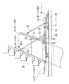
図1は、請求項1に記載の発明の一実施形態であるコンクリート高構造物構築装置を示す概略構成図である。
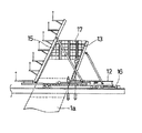
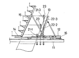
この装置は、図2に示すようなY型の橋脚1を構築するためのものである。この橋脚1は、プレストレストコンクリートからなる橋桁2の軸線方向に二つに分枝したものであり、図3に示すように、上記装置3はこの分枝した部分の双方を同時に構築することができるようになっている。
【0013】
そして、この装置3は、コンクリートの躯体1aから鋼棒によって吊り支持されるレール11と、このレール11上を走行可能に支持された第1の作業台12と、この作業台の上に設けられた第1の型枠13と、上記第1の作業台12上でこの第1の作業台の走行方向と同方向に移動可能に支持された第2の作業台14と、この第2の作業台14上に設けられた第2の型枠15とで主要部が構成されている。
【0014】
上記レール11は、図2に示すように、二つに分枝した橋脚の双方の側面に沿って連続して配置され、この橋脚のコンクリート躯体1aの両側に2組が設けられている。このレール11は、既に硬化したコンクリート躯体1aに固定されたブラケット21に鋼棒22を介して吊り支持されており、ブラケット21の上側に取り付けられたセンタホールジャッキ23によってこのレール11を引き上げることができるようになっている。
【0015】
上記第1の作業台12は、レール11上を走行する台車24に支持されており、レール11に固定されたジャッキ16(駆動装置)により、ロッド25を介して往復駆動されるものである。
上記第1の型枠13は、上記第1の作業台12上に下端を軸に回動可能に設けられ、橋脚の下側斜め側面の角度に合致するように斜支持部材26によって支持されている。この第1の型枠13は少なくとも一回のコンクリート打設分の高さを有する大型パネル状に組み立てられている。
【0016】
上記第2の作業台14は、第1の作業台12上に摺動可能に支持されており、センターホールジャッキ27(牽引装置)が装着された鋼棒28によって連結され、第1の作業台12に引き寄せることができるようになっている。
上記第2の型枠15は、橋脚の上側斜め側面の型枠となるものであり、第1の型枠13と同様に回動可能に支持され、斜支持部材29によってコンクリート躯体の側面の角度に設定される。また、この第2の型枠15には複数の作業足場30が一体に取り付けられている。
【0017】
次に上記のような構成のコンクリート高構造物構築装置を用いて、Y型の橋脚を構築する方法について説明する。なお、この方法は請求項2に記載の発明の一実施形態である。
図4に示すように、第1の型枠13および第2の型枠15を所定の位置に設置するとともに、これらと直角な面には現場でほぼ鉛直な型枠17を組み立てる。また、これに併行して所定の鉄筋を配置する。そして、上記型枠で囲まれた内側にコンクリートを打設する。
【0018】
コンクリートが硬化した後、鉛直な型枠17を解体して脱型するとともに、ジャッキ16(駆動装置)を作動して第1の作業台12をコンクリート躯体1aより後退させ、図5に示すように、この上に支持された第1の型枠13を脱型する。このとき第2の作業台14と第1の作業台12とは、相対移動を許容するようになっており、第2の型枠15はコンクリート躯体1aと当接して動かない。
【0019】
続いて、前々回のコンクリート打設によって形成された部分の躯体に取り付けられたブラケット21−1から新たに形成された部分に取り付けられたブラケット21−3に吊り材を移動する。
これにより、レール11を新たに形成された部分に係止された鋼棒22−3と、前回にコンクリートを打設した部分に係止された鋼棒22−2とによって本装置全体を吊り支持し、これらの鋼棒をセンターホールジャッキ23で引き上げることによってレール11及びこれに支持される作業台・型枠を上昇させる。
【0020】
これにともない、図6に示すように、第2の型枠15はコンクリート躯体1aから脱型され、第1の型枠13はコンクリート躯体の下側斜め側面に当接し、次のブロックのコンクリートを打設する位置に到達する。
【0021】
そして、次のブロックの鉄筋配置等を行い、第1の作業台12と第2の作業台14を連結する鋼棒28をセンターホールジャッキ27で引っ張ることによって、図7に示すように、第2の型枠15をコンクリート躯体1aに引き寄せ、所定位置に固定する。また、第1の型枠13と第2の型枠15との間には、これらと直角でほぼ鉛直な型枠を組み立て、次のブロックのコンクリートを打設する。
このような工程をくり返し行い、順次コンクリート躯体を上方に構築してゆく。
【0022】
上記実施の形態はY型橋脚を構築する場合について説明したが、請求項1に記載の装置は上記のように柱状のコンクリート躯体が斜めに構築される場合に限らず、鉛直に立ち上げられる場合にも用いることができる。この場合には第1および第2の作業台、第1および第2の型枠は一組のみを用い、型枠が作業台上でほぼ鉛直に支持されて前進または後退する。
【0023】
また、請求項2に記載の構築方法は、上記のようなY型橋脚に限らず、例えば斜張橋の主塔が斜めに立ち上げられる場合等にも適用することが可能である。
【0024】
【発明の効果】
以上説明したように、請求項1に記載したコンクリート高構造物構築装置では、第1の作業台がレール上において、駆動装置により往復駆動され、第1の型枠がこの第1の作業台上に、第2の型枠はこの第1の作業台上で移動可能な第2の作業台上に設けられているので、第1および第2の型枠を、第1の作業台の移動によって前進または後退させることができる。したがって、簡単な装置で脱型および型枠を所定位置に設置することが可能となる。
また、レールをコンクリート躯体から吊り支持し、これを引き上げることによって装置全体を容易に上昇させることができ、上方へコンクリートを立ち上げててゆく工程が簡略化される。
【0025】
一方、請求項2に記載のコンクリート斜柱の構築方法では、斜め側面の型枠を吊り支持された枠体上に前進および後退が可能に支持し、レールとともに型枠が上昇される工程で、下側の斜め側面の型枠を次にコンクリートを打設するための所定位置に移動するとともに、上側の斜め側面の型枠をコンクリート躯体から脱型することができる。このため、脱型および型枠を所定位置へ移動する工程が効率化され、能率のよいコンクリート斜柱の構築が可能となる。
【図面の簡単な説明】
【図1】請求項1に記載の発明の一実施形態であるコンクリート高構造物構築装置を示す概略構成図である。
【図2】図1に示す装置を用いて構築するのに適した橋脚の概略側面図である。
【図3】図2に示す橋脚を、図1に示す装置を用いて構築するときの状態を示す概略図である。
【図4】図1に示す装置を用いて、橋脚を構築するときの、1工程を示す概略図である。
【図5】図1に示す装置を用いて、橋脚を構築するときの、1工程を示す概略図である。
【図6】図1に示す装置を用いて、橋脚を構築するときの、1工程を示す概略図である。
【図7】図1に示す装置を用いて、橋脚を構築するときの、1工程を示す概略図である。
【符号の説明】
1 Y型の橋脚
2 橋桁
3 コンクリート高構造物構築装置
11 レール
12 第1の作業台
13 第1の型枠
14 第2の作業台
15 第2の型枠
16 ジャッキ(駆動装置)
17 型枠
21 ブラケット
22 鋼棒
23 センターホールジャッキ
24 台車
25 ロッド
26 斜支持部材
27 センターホールジャッキ(牽引装置)
28 鋼棒
29 斜支持部材
30 作業足場[0001]
BACKGROUND OF THE INVENTION
The present invention is used to construct a high-concrete structure, and includes a scaffold for work, a formwork for placing concrete, and a concrete high-structure constructing apparatus including a support for supporting these, and The present invention relates to a method of constructing a high structure including a concrete oblique column.
[0002]
[Prior art]
With the development of major roads such as highways, the construction of long-span bridges in mountainous areas has increased, and when they are bridged to valleys, they have become more than 50 m high piers. When constructing a concrete structure that can be raised up from the ground surface in this way, if the work is to be done by assembling a scaffold around the structure as is widely done in the past, the scaffold should have a high yield strength. It will need to be done and will be expensive. In particular, when a concrete structure is launched diagonally, it is necessary to assemble the scaffolding on the entire lower side of the inclined structure, which increases the temporary cost.
[0003]
For this reason, a construction method that eliminates the need for a scaffold assembled from the ground surface has been proposed, one of which is a jumping foam construction method. This uses, for example, an apparatus as disclosed in Japanese Patent Publication No. Sho 63-31629. A column that is already placed and hardened into concrete is raised upward, and a large panel is formed. Supports frames, scaffolding, etc. When the concrete placed above hardens and a sufficient strength is obtained, the tightness of the support is once released, and is raised to the upper block and fastened again. As a result, the formwork / scaffold can be installed at the concrete placement position of the upper block, and the concrete can be successively poured upward.
[0004]
[Problems to be solved by the invention]
However, the above construction method has the following problems.
In order to replace the support column upward, a means for temporarily supporting the formwork, scaffolding, etc. and releasing the connection of the support column to the concrete frame is required. In addition, a jack or the like that enables the formwork to advance and retreat is required in order to support the formwork by the struts tightly coupled to the concrete frame and to install the formwork at a predetermined position. Therefore, there is a problem that the apparatus becomes complicated and the production cost becomes high.
Furthermore, when the concrete structure is to be launched obliquely, a large bending moment acts on the support column due to its own weight on the formwork, scaffolding, etc., making it difficult to maintain sufficient safety.
[0005]
The present invention has been made in view of the above-described problems, and the purpose thereof is to construct a concrete high structure with a simple device, and when the structure is launched obliquely. The present invention is to provide a concrete high structure construction apparatus that can be applied to the concrete, and to provide a concrete oblique column construction method capable of safely constructing a concrete oblique column at a low cost.
[0006]
[Means for Solving the Problems]
In order to solve the above-mentioned problem, the invention according to claim 1 includes a rail suspended and supported from a concrete frame that has already been placed, a first work table supported so as to be able to run on the rail, A first formwork supported by the first workbench and formed into a large panel, the first formwork provided for placing new concrete on top of the concrete frame, and the first work A drive device that drives the platform so as to move forward and backward with respect to the side surface of the concrete frame; and a relative movement in the same direction as the direction in which the first work table is driven, supported by the first work table A second workbench that can be provided, and a second panel that has a large panel and is supported on the second workbench in opposition to the first workbench. A structure construction apparatus is provided.
[0007]
In such a concrete high structure construction apparatus, the first formwork formed into a large panel is supported on a first work table that can travel on a rail, and the first work table is supported by a drive device. By moving forward or backward with respect to the side surface of the concrete frame, the first formwork is set in place or removed from the cast concrete.
The second formwork is attached to the second worktable supported on the first worktable, and the first worktable and the second worktable are not moved relative to each other. When the first work table is driven by the drive device in the stopped state, the second formwork is also moved forward or backward with respect to the concrete frame, so that the mold can be removed from the concrete placed or placed at a predetermined position. Easy to do.
[0008]
In order to demold the first formwork on both sides of the concrete frame from the second formwork, each formwork must move in the opposite direction and cannot be performed at the same time. The engagement between the first work table and the second work table is released, both the work tables are locked again after removing the first formwork, and the first work is performed by the driving device. The second mold can be removed by driving the table. Therefore, it is possible to install or remove the molds formed into two large panels from a predetermined device with a single driving device.
In addition, when it is desirable in the process to move the second formwork after the first formwork is installed at a predetermined position, it is fixed to either the first workbench or the second workbench. A traction device that draws the other may be provided.
[0009]
And since the said 1st work bench is supported on the rail suspended and supported from the concrete frame, as the concrete is poured upward, the rail is lifted upward, and the above-mentioned formwork and work bench Will be used for the next concrete placement.
[0010]
The invention according to
[0011]
In such a construction method of a concrete oblique column, after placing concrete of one block, the formwork on the lower oblique side of the oblique pillar is retracted, and the work table and the formwork are lifted together with the frame body and raised. Thus, the operation of moving the lower oblique side mold to a predetermined position and the upper oblique side mold can be removed simultaneously. Therefore, after performing cleaning etc., the formwork on the upper oblique side can be moved to a predetermined position for placing the next block simply by pulling it toward the concrete frame side. Increased efficiency.
[0012]
DETAILED DESCRIPTION OF THE INVENTION
Hereinafter, embodiments of the invention according to the present application will be described with reference to the drawings.
FIG. 1 is a schematic configuration diagram showing a concrete high structure constructing apparatus according to an embodiment of the present invention.
This apparatus is for constructing a Y-type pier 1 as shown in FIG. This pier 1 is bifurcated in the axial direction of a
[0013]
The apparatus 3 is provided on a
[0014]
As shown in FIG. 2, the
[0015]
The first work table 12 is supported by a
The
[0016]
The
The
[0017]
Next, a method for constructing a Y-type pier using the concrete high structure constructing apparatus having the above configuration will be described. This method is an embodiment of the invention described in
As shown in FIG. 4, the
[0018]
After the concrete has hardened, the
[0019]
Subsequently, the suspension member is moved from the bracket 21-1 attached to the housing of the part formed by the previous concrete placement to the bracket 21-3 attached to the newly formed part.
As a result, the entire apparatus is suspended and supported by the steel bar 22-3 locked to the newly formed part of the
[0020]
Accordingly, as shown in FIG. 6, the
[0021]
Then, the reinforcing bars of the next block are arranged, and the
Such a process is repeated, and the concrete frame is sequentially constructed upward.
[0022]
Although the said embodiment demonstrated the case where a Y-type pier was constructed | assembled, the apparatus of Claim 1 is not only the case where a columnar concrete frame is constructed | assembled diagonally as mentioned above, but the case where it stands | starts up vertically Can also be used. In this case, only one set is used for the first and second work tables and the first and second molds, and the molds are supported substantially vertically on the work table and are moved forward or backward.
[0023]
The construction method according to
[0024]
【The invention's effect】
As described above, in the concrete high structure building apparatus according to claim 1, the first work table is reciprocated by the driving device on the rail, and the first formwork is mounted on the first work table. In addition, since the second formwork is provided on the second worktable movable on the first worktable, the first and second formwork can be moved by moving the first worktable. Can move forward or backward. Therefore, it is possible to remove the mold and set the mold at a predetermined position with a simple device.
Also, the entire apparatus can be easily raised by suspending and supporting the rail from the concrete frame and pulling it up, and the process of raising the concrete upward is simplified.
[0025]
On the other hand, in the construction method of the concrete oblique column according to
[Brief description of the drawings]
FIG. 1 is a schematic configuration diagram showing a concrete high structure construction apparatus according to an embodiment of the invention described in claim 1;
2 is a schematic side view of a pier suitable for construction using the apparatus shown in FIG.
FIG. 3 is a schematic view showing a state when the pier shown in FIG. 2 is constructed using the apparatus shown in FIG.
FIG. 4 is a schematic view showing one process when a pier is constructed using the apparatus shown in FIG. 1;
FIG. 5 is a schematic view showing one step when a pier is constructed using the apparatus shown in FIG. 1;
FIG. 6 is a schematic view showing one step when a pier is constructed using the apparatus shown in FIG. 1;
FIG. 7 is a schematic view showing one step when a pier is constructed using the apparatus shown in FIG. 1;
[Explanation of symbols]
DESCRIPTION OF SYMBOLS 1 Y-
17
28
Claims (2)
このレール上に走行可能に支持された第1の作業台と、
前記第1の作業台に支持され、大型パネル化された型枠であって、前記コンクリート躯体の上部に新たなコンクリートを打設するために設けられる第1の型枠と、
前記第1の作業台を、前記コンクリート躯体の側面に対して前進および後退するように駆動する駆動装置と、
前記第1の作業台に支持され、この第1の作業台が駆動される方向と同方向に相対移動が可能に設けられた第2の作業台と、
大型パネル化され、前記第1の型枠と対向して前記第2の作業台上に支持された第2の型枠と、を有することを特徴とするコンクリート高構造物構築装置。A rail suspended from a concrete frame that has already been placed, and
A first workbench movably supported on the rail;
A first formwork supported by the first workbench and formed into a large panel, which is provided for placing new concrete on top of the concrete frame;
A driving device for driving the first work table so as to move forward and backward with respect to a side surface of the concrete frame;
A second workbench supported by the first workbench and provided so as to be relatively movable in the same direction as the direction in which the first workbench is driven;
A high-concrete structure building apparatus comprising: a second panel formed in a large panel and supported on the second workbench in opposition to the first mold.
既に打設されたコンクリート躯体に吊り支持された枠体上に、作業台を介して下側斜め側面の型枠を設け、
前記作業台が前記枠体上を移動することによって上記下側斜め側面の型枠が躯体面に対して進退が可能となるように支持し、
上側斜め側面の型枠は、前記作業台に、躯体面に対して進退する方向に該作業台と相対移動が可能となるように支持し、
前記型枠内にコンクリートを打設し、
このコンクリートが硬化した後に、前記作業台の移動によって下側斜め側面の型枠を後退させ、次にコンクリートを打設する部分に対して型枠を設置する位置のほぼ直下に設置し、
吊り支持された前記枠体を上方に引上げることによって前記下側斜め側面の型枠を、次にコンクリートを打設する部分の所定位置に移動するとともに、前記上側斜め側面の型枠を脱型し、
前記下側斜め側面の型枠に前記上側斜め側面の型枠を引き寄せて所定位置に固定し、コンクリートを打設する工程を含むことを特徴とするコンクリート斜柱の構築方法。It is a method of constructing an oblique column of concrete by adding concrete sequentially upward using a work table supported by suspension and a large panel formwork,
On the frame that is suspended and supported by the concrete frame that has already been placed, a form on the lower oblique side is provided via a workbench,
The lower work surface is supported by the work table so that it can move forward and backward with respect to the housing surface by moving on the frame.
The upper oblique side formwork is supported on the workbench so that it can move relative to the workbench in a direction that moves forward and backward with respect to the housing surface.
Placing concrete in the formwork,
After the concrete is hardened, the work table is moved to retreat the lower oblique side of the formwork, and then installed almost directly below the position where the formwork is placed against the part where the concrete is placed,
The lower oblique side mold is moved to a predetermined position of the portion where concrete is placed next by lifting the suspended and supported frame, and the upper oblique side mold is removed from the mold. And
A method for constructing a concrete oblique column, comprising the steps of drawing the upper oblique side formwork to the lower oblique side formwork and fixing it to a predetermined position, and placing concrete.
Priority Applications (1)
| Application Number | Priority Date | Filing Date | Title |
|---|---|---|---|
| JP16343997A JP3804883B2 (en) | 1997-06-05 | 1997-06-05 | Concrete high structure construction apparatus and concrete oblique column construction method |
Applications Claiming Priority (1)
| Application Number | Priority Date | Filing Date | Title |
|---|---|---|---|
| JP16343997A JP3804883B2 (en) | 1997-06-05 | 1997-06-05 | Concrete high structure construction apparatus and concrete oblique column construction method |
Publications (2)
| Publication Number | Publication Date |
|---|---|
| JPH10339033A JPH10339033A (en) | 1998-12-22 |
| JP3804883B2 true JP3804883B2 (en) | 2006-08-02 |
Family
ID=15773920
Family Applications (1)
| Application Number | Title | Priority Date | Filing Date |
|---|---|---|---|
| JP16343997A Expired - Fee Related JP3804883B2 (en) | 1997-06-05 | 1997-06-05 | Concrete high structure construction apparatus and concrete oblique column construction method |
Country Status (1)
| Country | Link |
|---|---|
| JP (1) | JP3804883B2 (en) |
Cited By (1)
| Publication number | Priority date | Publication date | Assignee | Title |
|---|---|---|---|---|
| CN111501531A (en) * | 2020-03-31 | 2020-08-07 | 上海城建市政工程(集团)有限公司 | Construction method of V-shaped thin-wall pier and 0# block main beam supporting system |
Families Citing this family (11)
| Publication number | Priority date | Publication date | Assignee | Title |
|---|---|---|---|---|
| CN103388308A (en) * | 2013-08-06 | 2013-11-13 | 中铁八局集团市政工程有限公司 | Secondary temporary pull rod structure protective construction method in large-sized symmetrical oblique pier construction |
| KR101889064B1 (en) * | 2016-11-18 | 2018-08-16 | 현대건설 주식회사 | Construction method of a long span bridge main tower |
| CN107386114A (en) * | 2017-07-17 | 2017-11-24 | 中交路桥华南工程有限公司 | Tilting pier shaft casting system |
| CN107386115A (en) * | 2017-07-17 | 2017-11-24 | 中交路桥华南工程有限公司 | Tilting pier shaft casting method |
| CN113585050A (en) * | 2020-04-30 | 2021-11-02 | 比亚迪股份有限公司 | Bridge pier |
| CN111926712B (en) * | 2020-08-12 | 2021-09-17 | 中交武汉港湾工程设计研究院有限公司 | Intelligent construction method for main tower with large inclination angle |
| CN112144417A (en) * | 2020-10-12 | 2020-12-29 | 中建八局第一建设有限公司 | Construction device and construction method for hollow coping of special-shaped pier gem |
| CN113123239A (en) * | 2021-04-07 | 2021-07-16 | 中国建筑第八工程局有限公司 | Construction method of special-shaped tower column structure |
| CN113981830A (en) * | 2021-11-11 | 2022-01-28 | 中交一公局集团有限公司 | V-shaped pier construction method |
| CN114320367B (en) * | 2021-12-31 | 2023-08-04 | 安徽水利开发有限公司 | City gate opening type small-end-face tunnel and construction method |
| CN114960452A (en) * | 2022-06-20 | 2022-08-30 | 中铁大桥局集团有限公司 | Template structure of large-inclination-angle concrete tower column and tower column construction method |
-
1997
- 1997-06-05 JP JP16343997A patent/JP3804883B2/en not_active Expired - Fee Related
Cited By (1)
| Publication number | Priority date | Publication date | Assignee | Title |
|---|---|---|---|---|
| CN111501531A (en) * | 2020-03-31 | 2020-08-07 | 上海城建市政工程(集团)有限公司 | Construction method of V-shaped thin-wall pier and 0# block main beam supporting system |
Also Published As
| Publication number | Publication date |
|---|---|
| JPH10339033A (en) | 1998-12-22 |
Similar Documents
| Publication | Publication Date | Title |
|---|---|---|
| JP3804883B2 (en) | Concrete high structure construction apparatus and concrete oblique column construction method | |
| JP3026161B2 (en) | Self-elevating formwork apparatus and method of lifting the apparatus | |
| KR20190041189A (en) | Modular work platform of a long span bridge main tower rebar and construction method using the same | |
| WO2022142193A1 (en) | Construction method for large-span thin-wall concrete sound barrier pouring trolley | |
| JP4329535B2 (en) | Mobile work vehicle for overhanging slabs | |
| JPH09125318A (en) | Construction device of bridge girder | |
| CN216765625U (en) | Integral hydraulic creeping formwork structure for double-column pier construction | |
| JP2829363B2 (en) | Formwork equipment for pillar construction | |
| JPH09125319A (en) | Construction method of bridge girder | |
| JPH04353105A (en) | Erecting method for bridge girder | |
| JP3425352B2 (en) | Self-elevating formwork device | |
| JPH0681314A (en) | Construction method for concrete main tower | |
| JP2000087315A (en) | Method and device for construction of floor slab | |
| JPS5916608B2 (en) | Concrete formwork method and its equipment | |
| JPH05195513A (en) | Lining work car for arch bridge | |
| CN113914232B (en) | High main tower inner formwork and scaffold integrated construction system and method | |
| JP2000087314A (en) | Method and device for construction of floor slab | |
| JPH0336362B2 (en) | ||
| JPH07102524A (en) | Method for building concrete cable-stayed bridge and form supporting truck using the same | |
| JP3873101B2 (en) | Equipment for placing slabs | |
| JP3368483B2 (en) | Bridge pier construction method | |
| JP3224152B2 (en) | Construction method of cross beam in concrete building | |
| JPS6331629B2 (en) | ||
| JPH0681321A (en) | Moving device for construction | |
| JPH01190877A (en) | Concrete column forming method |
Legal Events
| Date | Code | Title | Description |
|---|---|---|---|
| A977 | Report on retrieval |
Free format text: JAPANESE INTERMEDIATE CODE: A971007 Effective date: 20050909 |
|
| TRDD | Decision of grant or rejection written | ||
| A01 | Written decision to grant a patent or to grant a registration (utility model) |
Free format text: JAPANESE INTERMEDIATE CODE: A01 Effective date: 20060502 |
|
| A61 | First payment of annual fees (during grant procedure) |
Free format text: JAPANESE INTERMEDIATE CODE: A61 Effective date: 20060508 |
|
| R150 | Certificate of patent or registration of utility model |
Free format text: JAPANESE INTERMEDIATE CODE: R150 |
|
| FPAY | Renewal fee payment (event date is renewal date of database) |
Free format text: PAYMENT UNTIL: 20120519 Year of fee payment: 6 |
|
| FPAY | Renewal fee payment (event date is renewal date of database) |
Free format text: PAYMENT UNTIL: 20150519 Year of fee payment: 9 |
|
| R250 | Receipt of annual fees |
Free format text: JAPANESE INTERMEDIATE CODE: R250 |
|
| R250 | Receipt of annual fees |
Free format text: JAPANESE INTERMEDIATE CODE: R250 |
|
| LAPS | Cancellation because of no payment of annual fees |