JP3801503B2 - Hydraulic drive device and method for working machine - Google Patents
Hydraulic drive device and method for working machine Download PDFInfo
- Publication number
- JP3801503B2 JP3801503B2 JP2001389875A JP2001389875A JP3801503B2 JP 3801503 B2 JP3801503 B2 JP 3801503B2 JP 2001389875 A JP2001389875 A JP 2001389875A JP 2001389875 A JP2001389875 A JP 2001389875A JP 3801503 B2 JP3801503 B2 JP 3801503B2
- Authority
- JP
- Japan
- Prior art keywords
- engine
- torque
- signal
- load
- fuel flow
- Prior art date
- Legal status (The legal status is an assumption and is not a legal conclusion. Google has not performed a legal analysis and makes no representation as to the accuracy of the status listed.)
- Expired - Fee Related
Links
Images


Landscapes
- Operation Control Of Excavators (AREA)
- Control Of Vehicle Engines Or Engines For Specific Uses (AREA)
- Fluid-Pressure Circuits (AREA)
Description
【0001】
【発明の属する技術分野】
本発明は、油圧ショベルなどの作業機に設けられ、ガバナ領域をアイソクロナス特性に制御可能なエンジンと、このエンジンにより駆動される可変容量油圧ポンプとを備えた作業機の油圧駆動装置に関する。
【0002】
【従来の技術】
図6は一般的なエンジンのエンジン回転数とエンジン出力トルクの関係を表したものである。エンジンの出力は同図に示すごとく、ガバナ領域33と全負荷曲線30に分けられる。ガバナ領域33はガバナの開度が100%以下での出力領域であり、全負荷曲線はガバナ開度が100%の出力領域である。
【0003】
メカニカルガバナはフライウェイトとばねのつりあいによって燃料噴射量を調節する構造のため、メカニカルガバナを備えたエンジンのガバナ領域は図6のドループ特性線31のようになる。また一般に、エンジンの全負荷性能は全負荷曲線30のようになり、エンジン出力トルクTeが定格トルクT1からエンジン最大トルクTe 1まで増加していくとエンジン回転数Nは低下していく。
【0004】
以上のことから、メカニカルガバナを備えたエンジンでは無負荷最高回転数N2からエンジン最大トルクTe 1発生時のエンジン回転数N1の範囲内においては、エンジン出力トルクTeが増加するにつれて、すなわちエンジンにかかる負荷が大きくなるにつれて、エンジン回転数Nは低下していくという関係が成立する。ちなみに、最大トルクTe 1を超える負荷がエンジンに入力された場合は、エンジンストールとなる。
【0005】
ところで、メカニカルガバナを備えたエンジンを搭載する作業機において、エンジン馬力の有効活用及びエンスト防止等を目的とするスピードセンシング制御という従来技術が知られている。スピードセンシング制御は、メカニカルガバナを備えたエンジンの持つ「エンジン回転数の増減がほぼエンジンの負荷の増減と一致する」という特徴に着目した制御方法であり、エンジン回転数の変動に応じてポンプ吸収馬力を増減させる方法である。
【0006】
ここで、メカニカルガバナを備えたエンジンを搭載する作業機、例えば油圧ショベルに対して、スピードセンシング制御を適用したときの制御手順について、図7及び図8を用いて説明する。図7はエンジン回転数Nとエンジン出力トルクTe及びポンプ目標増減トルクΔTとの関係を示したものであり、図8はポンプ吐出圧力Pと吐出流量Qによる定馬力制御線図を示したものである。
【0007】
図7において、まずエンジン回転数Nからポンプ目標増減トルクΔTへの変換方法を特性線40のようにあらかじめ設定しておく(ポンプ目標増減トルクΔTは縦軸右側に表す)。次に、エンジン回転数検出器により導かれるエンジン回転数Nが定格回転数NOよりも大きい時はポンプ目標増減トルクΔTの値を0から増加させ(0<ΔT<ΔT3)、エンジン回転数Nが定格回転数NOよりも小さい時はポンプ目標増減トルクΔTの値を0から減少させる(ΔT2<ΔT<0)計算を行う。ここで、ΔT2とΔT3はポンプの機械的限界等により決まるポンプ目標増減トルクの下限値と上限値である。
【0008】
上記方法にて導いたポンプ目標増減トルクΔTの値に、ポンプ吸収トルク基準値TBを加算しポンプ吸収トルクTP(=ΔT+TB)を求める。ここで、ポンプ吸収トルク基準値TBとは、定格回転NOにおけるポンプ吸収トルクのことであり(ベーストルクとも呼ばれる)、一般に定格回転時のエンジントルクT1よりも小さくなるように設定される。
【0009】
次に、図8のポンプの吐出圧力Pと吐出流量Qの関係を示したP−Q線図において、前記ポンプ吸収トルクTPの値からポンプ吸収馬力が求められるので、前記ポンプ吸収トルクTPに基づいて、ポンプ吸収トルクがベーストルクTBに相当するポンプ吸収馬力を示す特性線41を、ΔT2減少分に相当するポンプ吸収馬力特性線42とΔT3増加分に相当する特性線43の範囲内にて増減させ、この吐出圧力Pと吐出流量Qの関係に基づき吐出圧力Pの変動に応じた吐出流量Qを求め、さらにこの吐出流量Qに応じたポンプ押し除け容積を求めレギュレータを制御する。
【0010】
このスピードセンシング制御を作業機に適用すると、以下の(1)〜(3)のような制御効果が得られる。
【0011】
(1)エンジン出力に余裕があるとき、すなわちエンジン回転数が定格回転数NOより大きくなったとき、ポンプ吸収馬力を増加させることでエンジン出力をより有効に活用できる。(増馬力制御)
(2)ターボ効き始めなどでエンジントルクが低下したとき、ポンプ吸収馬力を減じることでエンジンに過大なトルクがかかることを防ぎ、エンストを防止できる。(減馬力制御)
(3)エンジンの性能にばらつきが生じたとき、すなわち設計性能に対する製造上のばらつきや長時間稼働後の性能の低下等が生じても、性能に最適なポンプ吸収馬力に合わせることができる。(ばらつき補正)
ところで従来、上述のようなメカニカルガバナ式エンジンとは異なり、ガバナ領域33をアイソクロナス特性に制御可能な燃料噴射制御装置を有するエンジンを備えた作業機も提案されている。アイソクロナス制御を実現する制御方法としては、燃料噴射量を電子ガバナを用いて制御する方法、コモンレール式高圧燃料噴射制御システムやユニットインジェクター式燃料噴射制御システム等を用いて燃料の噴射圧力と噴射タイミングを制御する方法が知られており、ともにコンピュータで制御して実現する方法である。以下では電子ガバナを用いてアイソクロナス制御する作業機の例で説明する。
【0012】
この別の従来の作業機では、メカニカルガバナのようなフライウェイトの慣性による影響を生じることがなく、図6に示すように、エンジンの負荷の増減にかかわらず、すなわちエンジン出力トルクTeの増減にかかわらず、ガバナ領域33において、エンジン回転数Nを例えば定格回転数NOに一定に保つアイソクロナス制御が実施される。同図中、特性線32はアイソクロナス特性線を示す。このアイソクロナス制御により、メカニカルガバナを有するエンジンを備えた作業機に比べて低燃費及び低騒音を実現できる。
【0013】
【発明が解決しようとする課題】
ところで、スピードセンシング制御は、上述したように、メカニカルガバナを備えたエンジンの持つ「エンジン回転数の増減がほぼエンジンの負荷の増減と一致する」という特徴に着目し、エンジン回転数の変動に応じてポンプ吸収馬力を増減させる方法である。
【0014】
しかし、アイソクロナス制御を実現するエンジンを搭載する作業機にスピードセンシング制御を適用しても、アイソクロナス制御を実現するエンジンにあってはガバナ領域33でのエンジン回転数が定格回転数NOにて一定となるので、メカニカルガバナ式エンジンの「エンジン回転数の増減がほぼエンジンの負荷の増減と一致する」という関係が成り立たず、結果、前述の(1)増馬力制御、(3)ばらつき補正の効果が得られなくなる。
【0015】
本発明は以上の点を鑑みてなされたものであり、アイソクロナス特性を有するエンジンを搭載する作業機にあっても、メカニカルガバナを備えたエンジンを搭載する作業機にスピードセンシング制御を適用したときとほぼ同等の効果が得られる油圧駆動装置を提供することを目的とする。
【0016】
なお(2)減馬力制御に関しては、アイソクロナス特性エンジンにおいても、定格トルクT1を超える負荷が入力された場合、メカニカルガバナ式エンジンと同様にエンジン回転数Nは低下する特性を持つので、従来のスピードセンシング制御と同様の効果が得られる。
【0017】
【課題を解決するための手段】
上述した課題を解決するために、請求項1に記載の発明は、「ガバナ領域をアイソクロナス特性に制御可能な燃料噴射制御装置を有するエンジンと、前記エンジンにより駆動される可変容量油圧ポンプと、前記可変容量油圧ポンプの押し除け容積を制御するレギュレータと、前記可変容量油圧ポンプの吐出圧力を検出し吐出圧力信号を出力する圧力検出器と、前記可変容量油圧ポンプの前記押し除け容積に相当する傾転角を検出し傾転角信号を出力する傾転角検出器と、前記エンジンの回転数を検出しエンジン回転数信号を出力する回転数検出器と、前記エンジンにかかる負荷を検出しエンジン負荷信号を出力するエンジン負荷検出装置と、前記エンジン負荷信号を入力しエンジン負荷率を出力するエンジン負荷率演算手段と、前記エンジンの全負荷曲線を記憶しておく記憶装置とを備え、前記エンジン回転数信号と前記全負荷曲線からエンジン最大発生トルクを求め、前記エンジン最大発生トルクと前記エンジン負荷率から計算エンジントルクを求め、前記計算エンジントルクと前記吐出圧力信号と前記傾転角信号とからポンプ押除け容積を求め前記レギュレータを制御する制御手段とにより構成したことを特徴」とする構成としたことにある。
【0018】
この場合、請求項2に記載の発明のように、「前記エンジン負荷検出装置はエンジンのコントロールラック位置信号を出力し、前記エンジン負荷率演算手段は前記コントロールラック位置信号を入力しエンジン負荷率を出力する構成」としてもよい。
【0019】
また、請求項3に記載の発明のように、「前記エンジン負荷検出装置はエンジンの目標燃料流量信号または実燃料流量信号の少なくともどちらか一方を出力し、前記エンジン負荷率演算手段は前記目標燃料流量信号または前記実燃料流量信号の少なくともどちらか一方を入力し予め設定された全負荷状態燃料流量及び無負荷時燃料流量とからエンジン負荷率を出力する構成」としてもよい。
【0020】
請求項4に記載の発明は、作業機の油圧駆動方法を「ガバナ領域をアイソクロナス特性に制御可能な燃料噴射制御装置を有するエンジンと、このエンジンにより駆動される可変容量油圧ポンプと、エンジン負荷率を求める手段とを備えた作業機にあって、前記エンジン負荷率とエンジン回転数と予め設定されたエンジン全負荷曲線とから計算エンジントルクを求め、前記計算エンジントルクに基づきポンプ押し退け容積を増減させることを特徴」とすることにより課題の解決を図ったものである。
【0021】
この場合、請求項5に記載の発明のように、「前記エンジン負荷率をエンジンのコントロールラック位置信号により求めることを特徴とする」構成としてもよい。
【0022】
また、請求項6に記載の発明のように、「前記エンジン負荷率をエンジンの目標燃料流量または実燃料流量の少なくともどちらか一方と予め設定された全負荷状態燃料流量及び無負荷時燃料流量とにより求めることを特徴とする」構成としてもよい。
【0023】
【発明の実施の形態】
以下、本発明の作業機の油圧駆動装置の実施形態を、図1乃至図5に基づいて説明する。
【0024】
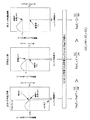
図1は本発明の作業機の油圧駆動装置の一実施形態を示す油圧回路図、図2は図1に示す一実施形態に備えられるコントローラの要部構成を示す図、図3は図2のエンジン全負荷トルク演算手段と計算エンジントルク演算手段を説明した図、図4は図2のポンプ目標増減トルク演算手段について説明した図、図5は本発明によるばらつき補正の作動方法について説明した図である。
【0025】
本実施形態は、アイソクロナス制御を実施するエンジンを備えた作業機に従来技術のスピードセンシング制御を適用した場合、(1)増馬力制御、(3)ばらつき補正制御の効果が得られないので、ここにエンジン負荷率信号をあらたに加えることにより(1)増馬力制御、(3)ばらつき補正制御の効果を得られるようにしたものである。
【0026】
本実施形態は、作業機、例えば油圧ショベルに備えられるもので、図1に示すように、ガバナ領域をアイソクロナス特性に制御可能な燃料噴射制御装置を有するエンジン1と、エンジン1にかかる負荷を検出するエンジン負荷検出装置12と、エンジン負荷検出装置12から出力される負荷信号Lを入力しエンジン1にかかる負荷の割合、すなわちエンジン負荷率信号LF[%]として出力するエンジン負荷率演算手段13とを備えている。
【0027】
ここで、エンジン負荷率信号LFの演算方法の一例を示す。この例は電子ガバナを有するエンジンにおける例であり、ガバナ内のコントロールラック位置と燃料噴射量はほぼ一致するという関係を利用したもので、エンジン全負荷状態でのコントロールラック位置を検出しこれをエンジン負荷率100%と定め、無負荷時でのコントロールラック位置を検出しこれを負荷率0%と定め、その間のコントロールラック位置信号からエンジンの負荷率を求める方法である。この方法によれば、図1のエンジン負荷検出装置12がコントロールラック位置検出装置、エンジン負荷率演算手段13がエンジン負荷検出装置12から検出された現在のコントロールラック位置信号を入力し、予め設定された全負荷状態でのコントロールラック位置及び無負荷時でのコントロールラック位置とからエンジン負荷率信号LFを計算する装置となる。
【0028】
また、エンジン負荷率信号LFの演算方法の他の例としては、図1のエンジン負荷検出装置12が現在の目標燃料流量を検出する装置、エンジン負荷率演算手段13が前記現在の目標燃料流量と予め設定されている全負荷状態燃料流量及び無負荷時燃料流量に基づき、次式よりエンジン負荷率を計算する装置がある。
【0029】
エンジン負荷率(%)=〔(現在の目標燃料流量−無負荷時燃料流量)/(全負荷状態燃料流量−無負荷時燃料流量)〕×100 …(1)
なお、上記の目標燃料流量の部分を実燃料流量に置換えた装置においてもエンジン負荷率を計算することができる。
【0030】
また本実施形態は、図1に示すように、エンジン1により駆動される可変容量油圧ポンプ2と、この可変容量油圧ポンプ2の押し除け容積を制御するレギュレータ16とを備えている。そして、油圧ポンプ2から吐出される圧油によって駆動する油圧シリンダ3、油圧モータ4、油圧シリンダ5、6等の複数の油圧アクチュエータと、これらの油圧アクチュエータに供給される圧油の流れを制御する方向制御弁7〜10と、メインリリーフ弁11と、油圧ポンプ2の吐出圧力を検出し吐出圧力信号Pを出力する圧力検出器14と、油圧ポンプ2の押し除け容積に相当する傾転角を検出し傾転角信号θを出力する傾転角検出器15と、エンジン1のエンジン回転数を検出しエンジン回転数信号Nを出力する回転数検出器17と、圧力検出器14から出力される吐出圧力信号P、及び傾転角検出器15から出力される傾転角信号θ、回転数検出器17から出力されるエンジン回転数信号N、エンジン負荷率演算手段13から出力されるエンジン負荷率信号LFを入力し、レギュレータ16に押し除け容積を制御する制御信号、すなわちレギュレータ目標値信号Rを出力するコントローラ18とを備えている。
【0031】
上述したコントローラ18の要部構成は、図2に示すように、大気圧や燃料の質などを標準状態としたときの全負荷性能をあらかじめエンジン単体ベンチ試験等で測定しておき、この測定データを記憶する記憶装置を備え、回転数検出器17から出力されるエンジン回転数Nが入力されたとき、そのエンジン回転数Nに相当するエンジン最大発生トルクEngFT(全負荷曲線上のトルク)を出力するエンジン全負荷出力トルク演算手段18aを含んでいる。
【0032】
エンジン全負荷トルク演算手段18aについて図3にて説明する。図3は縦軸左側に標準状態におけるエンジン出力トルク、横軸にエンジン回転数Nをあらわしたものであり、エンジン全負荷トルク演算手段18aは、例えばエンジン回転数Nが定格回転数NOの場合、定格回転数NOと同図の「18a内にて予め記憶しておいた標準状態における全負荷曲線」との交点を求め、この交点のエンジン出力トルクをエンジン最大発生トルクEngFTとして出力する。従って、スロットル開度が変更されエンジン回転数Nが変化したときは、再び交点を計算してこの交点に対応するエンジン最大発生トルクEngFTを出力する。
【0033】
また、エンジン全負荷出力トルク演算手段18aから出力されるエンジン最大発生トルクEngFTと、エンジン負荷率演算手段13から出力されるエンジン負荷率信号LF(%)とを入力し、計算式
EngT=EngFT×LF/100 …(2)
によって、計算エンジントルクEngTを求め、この計算エンジントルクEngTを出力する計算エンジントルク演算手段18bを含んでいる。
【0034】
計算エンジントルク演算手段18bについて図3にて説明する。例えばエンジン回転数Nが定格回転数NOの場合、エンジン負荷率信号LFは図3の縦軸右側で示すように定格出力時のエンジントルク点T1位置が100%となる。ちなみに、エンジン回転数Nが定格回転数NOと異なる場合は、そのエンジン回転数Nに相当する全負荷曲線上の点をLF=100%としたときのエンジン負荷の割合がエンジン負荷率となる。図3の一例のように、エンジン回転数Nが定格回転数NOのとき、エンジン負荷率演算手段13からLF=70%という値が出力され、エンジン全負荷トルク演算手段18bからEngFT=T1として出力され、これらの値が計算エンジントルク演算手段18bに入力されると、(2)式のような計算が行われ、結果、同図の縦軸左側に示すように、計算エンジントルクEngTが
EngT=0.7×T1
として出力される。
【0035】
なお、エンジン負荷率演算手段13により出力されるエンジン負荷率信号LFは、エンジンが実動状態で実際に発生している全負荷出力を100%としたときのエンジン負荷の割合であるから、エンジンの実動状態が上述した標準状態ならば、定格回転数NOかつLF=100%のとき、エンジンは定格出力トルクT1を発生していることになるが、エンジンの実動状態が例えば高地などのようにエンジン出力が低下するような状態では、定格回転数NOかつLF=100%であっても、実際にエンジンが出力している定格出力トルクはT1よりも小さい。
【0036】
また、コントローラ18は、計算エンジントルク演算手段18bから出力される計算エンジントルクEngTを入力し、計算エンジントルクEngTからポンプ目標増減トルクΔTを演算するポンプ目標トルク演算手段18cを含んでいる。
【0037】
図4に、計算エンジントルクEngTからポンプ目標増減トルクΔTへの演算手段の方法を示す。同図において、実線で示す特性線21は、従来技術のスピードセンシング制御と同じ制御効果を実現させるための特性線である。特性線21の計算エンジントルクEngTとポンプ目標増減トルクΔTの変化割合がEngT=T1の点をさかいに変化する、すなわち非線型となっているのは、図6に示すように、一般のエンジンではエンジン回転数Nとエンジン出力トルクTeとの変化割合がガバナ領域と全負荷領域をさかいに非線型となっているためである。言い換えると、従来のスピードセンシング制御では一般にエンジン回転数Nとポンプ目標増減トルクΔTの変化割合が線形となるように設定しているため、この変化割合を再現するためには、本発明の計算エンジントルクとポンプ目標増減トルクの変化の割合を特性線21のように設定する必要がある。
【0038】
また、ポンプ目標トルク演算手段18cから出力されるポンプ目標増減トルクΔTと、ベーストルクTBを設定するベーストルク設定手段18dから出力されるベーストルクTBとを加算して、ポンプ吸収トルクTPを出力する加算手段18eを含んでいる。
【0039】
また、加算手段18eから出力されるポンプ吸収トルクTPと、圧力検出器14から出力される吐出圧力信号Pと、傾転角検出器15から出力される傾転角信号θとを入力し、スピードセンシング制御と同様の手法により、レギュレータ16にポンプ押し除け容積を制御する制御信号Rを出力する吐出流量制御手段18fを含んでいる。
【0040】
このように構成したものでは、アイソクロナス特性エンジン1を搭載する作業機にあっても、メカニカルガバナを備えたエンジンを搭載する作業機にスピードセンシング制御を適用したときに得られる効果とほぼ同等の効果を得ることができる。なお、図4中のポイント▲1▼,▲2▼,▲3▼と、図7中のポイント▲1▼,▲2▼,▲3▼がそれぞれ対応していることになる。
【0041】
この方法により、ガバナ領域がアイソクロナス特性のエンジンに対しても増馬力制御が可能となり、メカニカルガバナを備えたエンジンを搭載する作業機にスピードセンシング制御を適用したときとほぼ同等の効果が得られる。
【0042】
また、図5はエンジンの出力にばらつきが生じたときについて説明したものであり、例として、定格出力のとき、出力が10%低下したときおよび出力が10%増加したときを示したものである。エンジン出力トルクが規定の性能より低下した場合は計算エンジントルクEngT1が定格出力時の計算エンジントルクEngT2の値よりも大きくなるため18c,18d,18eの演算手段を通じてポンプ吸収トルクTpは低減され、エンジン出力トルクが規定の性能より上昇した場合は計算エンジントルクEngT3が定格出力時の計算エンジントルクEngT2の値よりも小さくなるため18c,18d,18eの演算手段を通じてポンプ吸収トルクTpは増加される。これにより、エンジンの性能にばらつきが生じたときもスピードセンシング制御と同様、実際のエンジンの性能に最適なポンプ吸収馬力に合わせてエンジン出力を有効に活用することができる。
【0043】
また、計算エンジントルクEngTからポンプ目標増減トルクΔTへの演算方法は、図4に示すように、破線で示す特性線22、一点鎖線で示す特性線23のように自由に設定してもよい。
【0044】
図4において、特性線22のように設定する理由は以下の通りである。アイソクロナス特性に制御可能なエンジンを搭載する作業機にスピードセンシング制御をそのまま適用した場合、無負荷状態から急激に負荷がエンジンに入力されたときなどに生じる過渡的なエンジン回転数の落ち込み現象を、エンジンに定格を超えたトルクが働いたと判断してしまい、ポンプ目標増減トルクΔTを必要以上に下げてしまうという問題が生じる。そこで、計算エンジントルクEngTとポンプ目標増減トルクΔTの変化割合を特性線22のように設定する、すなわちエンジン負荷とポンプ目標増減トルクの変化割合を、特性線21に比べて小さく設定することにより、ポンプ目標増減トルクΔTを必要以上に下げるという悪影響を小さく抑えることができる。
【0045】
特性線23のように設定する理由は、特性線を線形にした方が制御手法としては単純になり制御が容易となるためである。
【0046】
なお、以上の説明では、図1においてエンジン負荷率演算手段13はコントローラ18と別に設ける例を説明したが、コントローラ18内に設けても良い。
【0047】
また、上記実施形態では、ガバナ領域をアイソクロナス特性に制御可能な燃料噴射制御装置として電子ガバナを例に説明してきたが、燃料噴射制御装置は電子ガバナだけに限られない。電子ガバナは、例えば特許第302153号公報に示すように、燃料噴射ポンプの燃料噴射量を調節するアクチュエータを位置制御する構成において、アクセル位置とエンジン回転数等の検出を基とする制御信号にて電磁弁を制御し、該アクチュエータを駆動させる装置である。これにより、電子ガバナはエンジンの負荷変動に関係無く燃料噴射量を調節することができるので、アイソクロナス特性を実現することができる。したがって、本発明は同様の負荷変動に関係無く燃料噴射量を調節することができる燃料噴射制御装置、例えばコモンレール式燃料噴射制御システムやユニットインジェクター式燃料噴射制御システム等を用いた構成にも適用することができる。
【0048】
【発明の効果】
本発明により以下のような効果が得られる。
【0049】
(増馬力制御に対し)ガバナ領域がアイソクロナス特性のエンジンに対しても増馬力制御が可能となる。
【0050】
(ばらつき補正に対し)エンジンの性能にばらつきが生じても、スピードセンシング制御と同様、性能に最適なポンプ吸収馬力に合わせることができる。
【0051】
従って、メカニカルガバナを備えたエンジンを搭載した作業機にスピードセンシング制御を適用したときとほぼ同等の効果が得られる油圧駆動装置を提供することができる。
【図面の簡単な説明】
【図1】本発明の作業機の油圧駆動装置の一実施形態を示す油圧回路図である。
【図2】図1に示す作業機の油圧駆動装置の一実施形態に備えられるコントローラの要部構成を示す図である。
【図3】図2のコントローラの要部構成のエンジン全負荷トルク演算手段と計算エンジントルク演算手段を説明した図である。
【図4】図2のコントローラの要部構成の計算エンジントルクEngTからポンプ目標増減トルクΔTへの演算手段を示す図である。
【図5】本発明によるエンジン性能にばらつきが生じたときの制御効果について説明した図である。
【図6】メカニカルガバナ式エンジンで得られるドループ特性、電子ガバナ等の燃料噴射制御装置で得られるアイソクロナス特性を対比して示したエンジン回転数・エンジントルク特性図である。
【図7】メカニカルガバナを備えたエンジンを搭載する作業機に、スピードセンシング制御を適用したときの、エンジン回転数に対するエンジンの全負荷性能及びガバナ特性と、ポンプ目標増減トルクを示した図である。
【図8】スピードセンシング制御の作動方法についてP―Q線図上にて説明した図である。
【符号の説明】
1 エンジン
2 可変容量油圧ポンプ
3 油圧シリンダ(油圧アクチュエータ)
4 油圧モータ(油圧アクチュエータ)
5 油圧シリンダ(油圧アクチュエータ)
6 油圧シリンダ(油圧アクチュエータ)
7 方向制御弁
8 方向制御弁
9 方向制御弁
10 方向制御弁
11 メインリリーフ弁
12 エンジン負荷検出装置
13 エンジン負荷率演算手段
14 圧力検出器
15 傾転角検出器
16 レギュレータ
17 回転数検出器
18 コントローラ
18a エンジン全負荷トルク演算手段
18b 計算エンジントルク演算手段
18c ポンプ目標増減トルク演算手段
18d ベーストルク設定手段
18e 加算手段
18f 制御手段(吐出流量制御手段)
21 スピードセンシング制御と同じ効果を実現させる特性線
22 過渡的なエンジン回転数の落ち込みを考慮した場合の特性線
23 制御の簡易化を狙った特性線
30 全負荷曲線
31 ドループ特性線
32 アイソクロナス特性線
33 ガバナ領域
40 スピードセンシング制御のポンプ目標増減トルク特性線
41 ポンプ吸収馬力特性線
42 ポンプ目標増減トルクをΔT2減少させたときのポンプ吸収馬力特性線43 ポンプ目標増減トルクをΔT3増加させたときのポンプ吸収馬力特性線[0001]
BACKGROUND OF THE INVENTION
The present invention relates to a hydraulic drive device for a work machine, which is provided in a work machine such as a hydraulic excavator and includes an engine capable of controlling a governor region to an isochronous characteristic and a variable displacement hydraulic pump driven by the engine.
[0002]
[Prior art]
FIG. 6 shows the relationship between the engine speed and engine output torque of a general engine. The engine output is divided into a
[0003]
Mechanical governor flyweightBecause of the structure in which the fuel injection amount is adjusted by balancing the spring and the spring, the governor region of the engine equipped with the mechanical governor is as shown by the
[0004]
From the above, in an engine equipped with a mechanical governor, the engine maximum torque Te 1Within the range of the engine speed N1 at the time of occurrence, the engine output torque TeAs the engine speed increases, that is, as the load on the engine increases, the relationship is established that the engine speed N decreases. By the way, the maximum torque Te 1When a load exceeding 1 is input to the engine, engine stall occurs.
[0005]
By the way, in a working machine equipped with an engine equipped with a mechanical governor, a conventional technique called speed sensing control for the purpose of effective use of engine horsepower, prevention of engine stall, and the like is known. Speed sensing control is a control method that focuses on the characteristic of an engine equipped with a mechanical governor that “increase / decrease in engine speed almost coincides with increase / decrease in engine load” and absorbs pumps according to fluctuations in engine speed. This is a method of increasing or decreasing horsepower.
[0006]
Here, a control procedure when speed sensing control is applied to a working machine equipped with an engine equipped with a mechanical governor, such as a hydraulic excavator, will be described with reference to FIGS. 7 and 8. FIG. 7 shows engine speed N and engine output torque T.eFIG. 8 is a diagram showing a constant horsepower control diagram based on the pump discharge pressure P and the discharge flow rate Q.
[0007]
In FIG. 7, first, a conversion method from the engine speed N to the pump target increase / decrease torque ΔT is set in advance as indicated by a characteristic line 40 (the pump target increase / decrease torque ΔT is represented on the right side of the vertical axis). Next, when the engine speed N guided by the engine speed detector is larger than the rated speed NO, the pump target increase / decrease torque ΔT is increased from 0 (0 <ΔT <ΔT).3) When the engine speed N is smaller than the rated speed NO, the pump target increase / decrease torque ΔT is decreased from 0 (ΔT).2<ΔT <0) Calculation is performed. Where ΔT2And ΔT3Are the lower limit value and the upper limit value of the pump target increase / decrease torque determined by the mechanical limit of the pump.
[0008]
The pump absorption torque reference value T is added to the pump target increase / decrease torque ΔT derived by the above method.BAnd pump absorption torque TP(= ΔT + TB) Here, pump absorption torque reference value TBIs the pump absorption torque at the rated rotation NO (also called base torque), and is generally the engine torque T at the rated rotation.1It is set to be smaller than that.
[0009]
Next, in the PQ diagram showing the relationship between the discharge pressure P and the discharge flow rate Q of the pump in FIG.PThe pump absorption horsepower is obtained from the value of the pump absorption torque TPThe pump absorption torque is based on the base torque TBThe
[0010]
When this speed sensing control is applied to a work machine, the following control effects (1) to (3) are obtained.
[0011]
(1) When there is a margin in the engine output, that is, when the engine speed becomes greater than the rated speed NO, the engine output can be utilized more effectively by increasing the pump absorption horsepower. (Horsepower control)
(2) When the engine torque is reduced due to the start of turbo effect or the like, it is possible to prevent excessive torque from being applied to the engine and reduce engine stall by reducing the pump absorption horsepower. (Horse reduction control)
(3) Even when the engine performance varies, that is, even when the manufacturing performance varies with respect to the design performance or the performance deteriorates after long-time operation, the pump absorption horsepower optimum for the performance can be adjusted. (Variation correction)
By the way, conventionally, unlike a mechanical governor type engine as described above, a work machine including an engine having a fuel injection control device capable of controlling the
[0012]
In this other conventional work machine, a fly like a mechanical governorweightAs shown in FIG. 6, regardless of the increase or decrease of the engine load, that is, the engine output torque TeRegardless of the increase / decrease, isochronous control is performed in the
[0013]
[Problems to be solved by the invention]
By the way, as described above, the speed sensing control pays attention to the characteristic of the engine equipped with the mechanical governor that “increase / decrease in engine speed substantially coincides with increase / decrease in engine load”, and responds to fluctuations in engine speed. This is a method of increasing or decreasing the pump absorption horsepower.
[0014]
However, even if speed sensing control is applied to a work machine equipped with an engine that realizes isochronous control, the engine speed in the
[0015]
The present invention has been made in view of the above points, and even when the speed sensing control is applied to a working machine equipped with an engine having a mechanical governor, even in a working machine equipped with an engine having isochronous characteristics. It is an object of the present invention to provide a hydraulic drive device that can obtain substantially the same effect.
[0016]
(2) Regarding the horsepower reduction control, the rated torque T is also applied to the isochronous engine.1When a load exceeding 1 is input, the engine speed N decreases as in the case of the mechanical governor type engine, so that the same effect as the conventional speed sensing control can be obtained.
[0017]
[Means for Solving the Problems]
In order to solve the above-mentioned problem, the invention according to
[0018]
In this case, as in the second aspect of the invention, “the engine load detection device outputs an engine control rack position signal, and the engine load factor calculation means inputs the control rack position signal to calculate the engine load factor. It is good also as a structure to output.
[0019]
According to a third aspect of the present invention, “the engine load detection device outputs at least one of an engine target fuel flow signal and an actual fuel flow signal, and the engine load factor calculation means outputs the target fuel flow signal. A configuration may be adopted in which at least one of the flow rate signal and the actual fuel flow rate signal is input and the engine load factor is output from a preset full load state fuel flow rate and a no-load fuel flow rate.
[0020]
According to a fourth aspect of the present invention, there is provided a hydraulic drive method for a work machine according to “an engine having a fuel injection control device capable of controlling a governor region to an isochronous characteristic, a variable displacement hydraulic pump driven by the engine, and an engine load factor. A calculating machine torque is calculated from the engine load factor, the engine speed and a preset engine full load curve, and the pump displacement volume is increased or decreased based on the calculated engine torque. This is a solution to the problem.
[0021]
In this case, as in the invention described in claim 5, it may be configured such that “the engine load factor is obtained from an engine control rack position signal”.
[0022]
Further, as in the sixth aspect of the present invention, “the engine load factor is determined by setting at least one of the target fuel flow rate and the actual fuel flow rate of the engine, the preset full load state fuel flow rate and the no-load fuel flow rate. It is good also as a structure characterized by calculating | requiring by.
[0023]
DETAILED DESCRIPTION OF THE INVENTION
Hereinafter, an embodiment of a hydraulic drive device for a working machine according to the present invention will be described with reference to FIGS.
[0024]
FIG. 1 is a hydraulic circuit diagram showing an embodiment of a hydraulic drive device for a working machine according to the present invention, FIG. 2 is a diagram showing a main part configuration of a controller provided in the embodiment shown in FIG. 1, and FIG. FIG. 4 is a diagram illustrating the engine full load torque calculating means and the calculated engine torque calculating means, FIG. 4 is a diagram illustrating the pump target increase / decrease torque calculating means of FIG. 2, and FIG. 5 is a diagram illustrating an operation method of variation correction according to the present invention. is there.
[0025]
In the present embodiment, when the conventional speed sensing control is applied to a work machine having an engine for performing isochronous control, the effects of (1) horsepower control and (3) variation correction control cannot be obtained. In addition, an effect of (1) horsepower control and (3) variation correction control can be obtained by newly adding an engine load factor signal.
[0026]
The present embodiment is provided in a work machine, for example, a hydraulic excavator. As shown in FIG. 1, an
[0027]
Here, an example of a calculation method of the engine load factor signal LF is shown. This example is an example of an engine having an electronic governor, which utilizes the relationship that the control rack position in the governor and the fuel injection amount substantially coincide with each other, and detects the control rack position in the engine full load state. This is a method of determining the load factor of 100%, detecting the control rack position when there is no load, determining this as a load factor of 0%, and determining the load factor of the engine from the control rack position signal during that time. According to this method, the engine
[0028]
As another example of the calculation method of the engine load factor signal LF, the engine
[0029]
Engine load factor (%) = [(current target fuel flow rate−no load fuel flow rate) / (full load fuel flow rate−no load fuel flow rate)] × 100 (1)
The engine load factor can also be calculated in an apparatus in which the target fuel flow rate is replaced with the actual fuel flow rate.
[0030]
In addition, as shown in FIG. 1, this embodiment includes a variable displacement
[0031]
As shown in FIG. 2, the configuration of the main part of the
[0032]
The engine full load torque calculating means 18a will be described with reference to FIG. FIG. 3 shows the engine output torque in the standard state on the left side of the vertical axis and the engine speed N on the horizontal axis, and the engine full load torque calculating means 18a is, for example, when the engine speed N is the rated speed NO, The intersection of the rated rotational speed NO and the “full load curve in the standard state stored in advance in 18a” in the same figure is obtained, and the engine output torque at this intersection is output as the engine maximum generated torque EngFT. Therefore, when the throttle opening is changed and the engine speed N changes, the intersection is calculated again and the engine maximum generated torque EngFT corresponding to this intersection is output.
[0033]
Further, the engine maximum generated torque EngFT output from the engine full load output torque calculating means 18a and the engine load factor signal LF (%) output from the engine load factor calculating means 13 are input, and the calculation formula
EngT = EngFT × LF / 100 (2)
The calculation engine torque EngT is calculated, and the calculation engine torque calculation means 18b for outputting the calculation engine torque EngT is included.
[0034]
The calculated engine torque calculating means 18b will be described with reference to FIG. For example, when the engine speed N is the rated speed NO, the engine load factor signal LF is the engine torque point T at the rated output as shown on the right side of the vertical axis in FIG.1The position becomes 100%. Incidentally, when the engine speed N is different from the rated speed NO, the engine load ratio is the engine load ratio when the point on the full load curve corresponding to the engine speed N is LF = 100%. As in the example of FIG. 3, when the engine speed N is the rated speed NO, the engine load factor calculating means 13 outputs a value of LF = 70%, and the engine full load torque calculating means 18b is EngFT = T.1When these values are input to the calculated engine torque calculating means 18b, the calculation as shown in the equation (2) is performed. As a result, as shown on the left side of the vertical axis in FIG.
EngT = 0.7 × T1
Is output as
[0035]
The engine load factor signal LF output by the engine load factor calculating means 13 is a ratio of the engine load when the total load output actually generated in the engine operating state is 100%. If the actual operating state of the engine is the standard state described above, the engine is operated at the rated output torque T when the rated rotational speed is NO and LF = 100%.1However, when the engine output is low, such as at high altitudes, the engine actually does not operate even if the rated speed is NO and LF = 100%. The rated output torque being output is T1Smaller than.
[0036]
The
[0037]
FIG. 4 shows a method of calculating means from the calculated engine torque EngT to the pump target increase / decrease torque ΔT. In the figure, a
[0038]
Further, the pump target increase / decrease torque ΔT output from the pump target torque calculation means 18c and the base torque TBThe base torque T output from the base torque setting means 18d for settingBAnd the pump absorption torque TPIs added.
[0039]
The pump absorption torque T output from the adding means 18ePAnd the discharge pressure signal P output from the
[0040]
With such a configuration, even if the working machine is equipped with the isochronous
[0041]
This method makes it possible to control the horsepower even for an engine having an governor region of isochronous characteristics, and an effect almost equivalent to that obtained when speed sensing control is applied to a working machine equipped with an engine equipped with a mechanical governor can be obtained.
[0042]
FIG. 5 illustrates the case where the output of the engine varies. For example, when the output is rated, the output decreases by 10% and the output increases by 10%. . If engine output torque falls below the specified performance, calculate engine torque EngT1Calculated engine torque EngT at rated output2Pump absorption torque T through the calculation means 18c, 18d, and 18e.pIf the engine output torque rises above the specified performance, the calculated engine torque EngT3Calculated engine torque EngT at rated output2The pump absorption torque T through the calculation means 18c, 18d, 18epWill be increased. As a result, when the engine performance varies, the engine output can be effectively utilized in accordance with the pump absorption horsepower optimum for the actual engine performance, as in the speed sensing control.
[0043]
Further, the calculation method from the calculated engine torque EngT to the pump target increase / decrease torque ΔT may be freely set as shown by a
[0044]
In FIG. 4, the reason for setting the
[0045]
The reason for setting the
[0046]
In the above description, the engine load factor calculation means 13 is provided separately from the
[0047]
In the above embodiment, an electronic governor has been described as an example of a fuel injection control device capable of controlling the governor region to isochronous characteristics, but the fuel injection control device is not limited to the electronic governor. Electronic governors are, for example, patentsThirdAs shown in Japanese Patent Laid-Open No. 02153, in a configuration for controlling the position of an actuator that adjusts the fuel injection amount of a fuel injection pump, a solenoid valve is controlled by a control signal based on detection of an accelerator position, an engine speed, etc. It is a device for driving an actuator. As a result, the electronic governor can adjust the fuel injection amount regardless of engine load fluctuations, so that isochronous characteristics can be realized. Therefore, the present invention is also applied to a configuration using a fuel injection control device capable of adjusting the fuel injection amount regardless of the same load fluctuation, for example, a common rail fuel injection control system or a unit injector fuel injection control system. be able to.
[0048]
【The invention's effect】
The following effects can be obtained by the present invention.
[0049]
(With respect to the horsepower control) The horsepower control can be performed even for an engine whose governor region has an isochronous characteristic.
[0050]
Even if there is a variation in engine performance (as opposed to variation correction), it is possible to match the pump absorption horsepower optimum for the performance, as in the case of speed sensing control.
[0051]
Therefore, it is possible to provide a hydraulic drive device that can obtain substantially the same effect as when speed sensing control is applied to a working machine equipped with an engine equipped with a mechanical governor.
[Brief description of the drawings]
FIG. 1 is a hydraulic circuit diagram showing an embodiment of a hydraulic drive device for a working machine according to the present invention.
FIG. 2 is a diagram showing a main configuration of a controller provided in an embodiment of the hydraulic drive device for the working machine shown in FIG. 1;
3 is a diagram for explaining engine full load torque calculation means and calculation engine torque calculation means of the main configuration of the controller of FIG. 2; FIG.
4 is a diagram showing a calculation means for calculating a pump target increase / decrease torque ΔT from a calculated engine torque EngT of the main configuration of the controller of FIG. 2; FIG.
FIG. 5 is a diagram illustrating a control effect when variation occurs in engine performance according to the present invention.
FIG. 6 is an engine speed / torque torque characteristic chart showing a comparison between a droop characteristic obtained with a mechanical governor type engine and an isochronous characteristic obtained with a fuel injection control device such as an electronic governor.
FIG. 7 is a diagram showing engine full load performance with respect to engine speed and governor characteristics and pump target increase / decrease torque when speed sensing control is applied to a work machine equipped with an engine equipped with a mechanical governor. .
FIG. 8 is a diagram illustrating an operation method of speed sensing control on a PQ diagram.
[Explanation of symbols]
1 engine
2 Variable displacement hydraulic pump
3 Hydraulic cylinder (hydraulic actuator)
4 Hydraulic motor (hydraulic actuator)
5 Hydraulic cylinder (hydraulic actuator)
6 Hydraulic cylinder (hydraulic actuator)
7-way control valve
8-way control valve
9-way control valve
10-way control valve
11 Main relief valve
12 Engine load detection device
13 Engine load factor calculation means
14 Pressure detector
15 Tilt angle detector
16 Regulator
17 Speed detector
18 Controller
18a Engine full load torque calculation means
18b Calculation engine torque calculation means
18c Pump target increase / decrease torque calculation means
18d Base torque setting means
18e addition means
18f Control means (discharge flow rate control means)
21 Characteristic line to achieve the same effect as speed sensing control
22 Characteristic line when considering transient drop in engine speed
23 Characteristic lines aimed at simplifying control
30 Full load curve
31 Droop characteristic line
32 Isochronous characteristic line
33 Governor area
40 Pump target increase / decrease torque characteristic line for speed sensing control
41 Pump absorption horsepower characteristic line
42 Pump absorption horsepower characteristic line when pump target increase / decrease torque is decreased by
Claims (6)
前記エンジンにより駆動される可変容量油圧ポンプと、
前記可変容量油圧ポンプの押し除け容積を制御するレギュレータと、
前記可変容量油圧ポンプの吐出圧力を検出し吐出圧力信号を出力する圧力検出器と、
前記可変容量油圧ポンプの前記押し除け容積に相当する傾転角を検出し傾転角信号を出力する傾転角検出器と、
前記エンジンの回転数を検出しエンジン回転数信号を出力する回転数検出器と、
前記エンジンにかかる負荷を検出しエンジン負荷信号を出力するエンジン負荷検出装置と、
前記エンジン負荷信号を入力しエンジン負荷率を出力するエンジン負荷率演算手段と、
前記エンジンの全負荷曲線を記憶しておく記憶装置とを備え、
前記エンジン回転数信号と前記全負荷曲線からエンジン最大発生トルクを求め、前記エンジン最大発生トルクと前記エンジン負荷率から計算エンジントルクを求め、前記計算エンジントルクと前記吐出圧力信号と前記傾転角信号とからポンプ押除け容積を求め前記レギュレータを制御する制御手段とにより構成したことを特徴とする作業機の油圧駆動装置。An engine having a fuel injection control device capable of controlling the governor region to isochronous characteristics;
A variable displacement hydraulic pump driven by the engine;
A regulator for controlling the displacement volume of the variable displacement hydraulic pump;
A pressure detector that detects a discharge pressure of the variable displacement hydraulic pump and outputs a discharge pressure signal;
A tilt angle detector that detects a tilt angle corresponding to the displacement volume of the variable displacement hydraulic pump and outputs a tilt angle signal;
A rotational speed detector for detecting the rotational speed of the engine and outputting an engine rotational speed signal;
An engine load detection device for detecting a load applied to the engine and outputting an engine load signal;
Engine load factor calculating means for inputting the engine load signal and outputting the engine load factor;
A storage device for storing the full load curve of the engine,
The engine maximum generated torque is obtained from the engine speed signal and the full load curve, the calculated engine torque is obtained from the engine maximum generated torque and the engine load factor, the calculated engine torque, the discharge pressure signal, and the tilt angle signal. And a control means for controlling the regulator by obtaining a pump displacement volume.
前記エンジン負荷率とエンジン回転数と予め設定されたエンジン全負荷曲線とから計算エンジントルクを求め、前記計算エンジントルクに基づきポンプ押し退け容積を増減させることを特徴とする作業機の油圧駆動方法。An engine having a fuel injection control device capable of controlling a governor region to isochronous characteristics, a variable displacement hydraulic pump driven by the engine, and means for obtaining an engine load factor,
A hydraulic drive method for a working machine, characterized in that a calculated engine torque is obtained from the engine load factor, the engine speed, and a preset engine full load curve, and the pump displacement is increased or decreased based on the calculated engine torque.
Priority Applications (1)
| Application Number | Priority Date | Filing Date | Title |
|---|---|---|---|
| JP2001389875A JP3801503B2 (en) | 2001-12-21 | 2001-12-21 | Hydraulic drive device and method for working machine |
Applications Claiming Priority (1)
| Application Number | Priority Date | Filing Date | Title |
|---|---|---|---|
| JP2001389875A JP3801503B2 (en) | 2001-12-21 | 2001-12-21 | Hydraulic drive device and method for working machine |
Publications (3)
| Publication Number | Publication Date |
|---|---|
| JP2003184604A JP2003184604A (en) | 2003-07-03 |
| JP2003184604A5 JP2003184604A5 (en) | 2005-01-06 |
| JP3801503B2 true JP3801503B2 (en) | 2006-07-26 |
Family
ID=27597966
Family Applications (1)
| Application Number | Title | Priority Date | Filing Date |
|---|---|---|---|
| JP2001389875A Expired - Fee Related JP3801503B2 (en) | 2001-12-21 | 2001-12-21 | Hydraulic drive device and method for working machine |
Country Status (1)
| Country | Link |
|---|---|
| JP (1) | JP3801503B2 (en) |
Families Citing this family (5)
| Publication number | Priority date | Publication date | Assignee | Title |
|---|---|---|---|---|
| JP4747953B2 (en) * | 2006-05-31 | 2011-08-17 | 井関農機株式会社 | Tractor |
| JP5401992B2 (en) * | 2009-01-06 | 2014-01-29 | コベルコ建機株式会社 | Power source device for hybrid work machine |
| JP5808726B2 (en) * | 2012-11-15 | 2015-11-10 | 株式会社竹内製作所 | Hydraulic drive |
| CN108757415B (en) * | 2018-05-24 | 2020-01-10 | 徐工集团工程机械有限公司 | Driving system and control method of throwing device and sand throwing and fire extinguishing train |
| CN114233485B (en) * | 2021-12-22 | 2023-09-15 | 潍柴动力股份有限公司 | Power system control method, device, system and storage medium |
-
2001
- 2001-12-21 JP JP2001389875A patent/JP3801503B2/en not_active Expired - Fee Related
Also Published As
| Publication number | Publication date |
|---|---|
| JP2003184604A (en) | 2003-07-03 |
Similar Documents
| Publication | Publication Date | Title |
|---|---|---|
| US8162618B2 (en) | Method and device for controlling pump torque for hydraulic construction machine | |
| AU2007330245B2 (en) | Torque controller of three pump system for construction machinery | |
| KR101512207B1 (en) | Engine control device for construction machine | |
| US6823672B2 (en) | Control device for construction machine | |
| KR101637571B1 (en) | Hydraulic pump control apparatus and control method for construction machinery | |
| KR20040007574A (en) | Method and device for controlling an electrically driven charger | |
| JP5124049B2 (en) | Engine control device | |
| CN112673136B (en) | Apparatus with hydraulic machine controller | |
| JP4342848B2 (en) | Hydraulic drive device for work equipment | |
| KR20170039157A (en) | Shovel | |
| JP3801503B2 (en) | Hydraulic drive device and method for working machine | |
| CN110886824B (en) | Hydraulic equipment | |
| JP2020037480A (en) | Crane and crane control method | |
| JP4109405B2 (en) | Engine control device for construction machinery | |
| KR20110088534A (en) | Method and device for controlling diesel engine, and ship with same | |
| KR101438227B1 (en) | Number of revolutions decline arrester equipment that use hydraulic pump maximum horsepower control of construction machinery | |
| KR20110073710A (en) | Hydraulic pump control apparatus for construction machinery and hydraulic pump control method for the same | |
| JP4773990B2 (en) | Torque control device for 3-pump system for construction machinery | |
| JP6819473B2 (en) | Fan controller | |
| JP3892306B2 (en) | Method and apparatus for checking engine performance of work machine and pump control apparatus | |
| JP4042296B2 (en) | Industrial engine control equipment | |
| JP3314143B2 (en) | Engine control method for construction machinery | |
| JP3606701B2 (en) | Pump operation control device | |
| JP2553978Y2 (en) | Control device for prime mover and hydraulic circuit of construction machinery | |
| KR20110073711A (en) | Power control apparatus for construction machinery |
Legal Events
| Date | Code | Title | Description |
|---|---|---|---|
| A977 | Report on retrieval |
Free format text: JAPANESE INTERMEDIATE CODE: A971007 Effective date: 20060214 |
|
| TRDD | Decision of grant or rejection written | ||
| A01 | Written decision to grant a patent or to grant a registration (utility model) |
Free format text: JAPANESE INTERMEDIATE CODE: A01 Effective date: 20060418 |
|
| A61 | First payment of annual fees (during grant procedure) |
Free format text: JAPANESE INTERMEDIATE CODE: A61 Effective date: 20060425 |
|
| R150 | Certificate of patent or registration of utility model |
Free format text: JAPANESE INTERMEDIATE CODE: R150 |
|
| FPAY | Renewal fee payment (event date is renewal date of database) |
Free format text: PAYMENT UNTIL: 20090512 Year of fee payment: 3 |
|
| FPAY | Renewal fee payment (event date is renewal date of database) |
Free format text: PAYMENT UNTIL: 20100512 Year of fee payment: 4 |
|
| FPAY | Renewal fee payment (event date is renewal date of database) |
Free format text: PAYMENT UNTIL: 20110512 Year of fee payment: 5 |
|
| LAPS | Cancellation because of no payment of annual fees |