JP3801059B2 - Robot joint structure - Google Patents
Robot joint structure Download PDFInfo
- Publication number
- JP3801059B2 JP3801059B2 JP2002023856A JP2002023856A JP3801059B2 JP 3801059 B2 JP3801059 B2 JP 3801059B2 JP 2002023856 A JP2002023856 A JP 2002023856A JP 2002023856 A JP2002023856 A JP 2002023856A JP 3801059 B2 JP3801059 B2 JP 3801059B2
- Authority
- JP
- Japan
- Prior art keywords
- arm
- frame
- cable
- insertion hole
- robot
- Prior art date
- Legal status (The legal status is an assumption and is not a legal conclusion. Google has not performed a legal analysis and makes no representation as to the accuracy of the status listed.)
- Expired - Lifetime
Links
Images


Description
【0001】
【発明の属する技術分野】
本発明は、第1のアームのフレームに軸部を介して第2のアームのフレームを回転可能に連結すると共に、第2のアームのフレームに、軸部の外周側に位置してケーブルの通路となる配線挿通孔を設けるようにしたロボットの関節部構造に関する。
【0002】
【発明が解決しようとする課題】
例えば複数のアームを順に回転可能に連結した多関節型ロボットにおいては、アームの内部を配線(ケーブル)が通されるようになっている。例えば、小型水平多関節ロボットにおける、第1アームと第2アームとの関節部分にあっては、第1アームのフレームに、第2アームのフレームが回動可能に連結されており、その第2アームのフレームに形成された挿通孔内をケーブル(配線)が通されるようになっている。
【0003】
この場合、第2アームの第1アームに対する相対回転に伴い、ケーブルが、第1アームのフレームに挟み込まれ、ひいては断線してしまうといったこと防止するため、前記挿通孔を周方向に円弧状に延びる長孔状として、ケーブルがその挿通孔内を相対的に移動できるようにすることが考えられている。尚、この場合、第1アームに対する第2アームの回動範囲が、ソフトウエア的及びハードウエア的に規制されるようになっているのであるが、上記挿通孔を長孔としてケーブルがその中を移動し得ることにより、比較的広い回動範囲を確保できるようになっている。
【0004】
しかしながら、上記のように挿通孔を長孔としたものでも、ケーブルの挟み込みはなくなるものの、軸方向に見て挿通孔が第1アームのフレームにラップする位置まで第2アームが回動すると、ケーブルが金属(鋳物)製の第1アームのフレームに直接接触することがあるため、ケーブルが擦れてその被覆が傷んだり、悪くすると断線したりする虞は依然として残っていた。
【0005】
本発明は上記事情に鑑みてなされたもので、その目的は、軸部の外周側に位置してケーブルの通路となる配線挿通孔を設けるようにしたものにあって、ケーブルがアームのフレームに直接接触することを防止してケーブルの保護を図ることができるロボットの関節部構造を提供するにある。
【0006】
【課題を解決するための手段】
上記目的を達成するために、本発明のロボットの関節部構造は、第2のアームのフレームに設けられる配線挿通孔を、周方向に延びる長孔状に形成すると共に、ケーブルを、その配線挿通孔の内部を周方向にスライド移動自在に設けられた内側ケーブルホルダに保持させた状態で設け、第2のアームの第1のアームに対する相対回転に応じて、その内側ケーブルホルダが第1のアームのフレームに当接するように構成したものである(請求項1の発明)。
【0007】
これによれば、ケーブルは、内側ケーブルホルダに保持された状態で配線挿通孔内を通されることにより、第1のアームのフレームにその配線挿通孔がラップする位置まで第2のアームが回転しても、内側ケーブルホルダが第1のアームのフレームに当接するだけで、ケーブルが、第1のアームのフレームに直接接触することを防止することができる。また、内側ケーブルホルダが第1のアームのフレームに当接した場合でも、その内側ケーブルホルダがケーブルを保持した状態で長孔状の配線挿通孔内を相対的にスライド移動することにより、第2のアームの第1のアームに対する所要の回動範囲を確保することができる。
【0008】
従って、請求項1のロボットの関節部構造によれば、配線挿通孔に要求される機能を確保した状態で、ケーブルが第1のアームのフレームに直接接触することを防止してケーブルの保護を図ることができ、また、内側ケーブルホルダを設けるだけの簡単な構成で済ませることができる。尚、本発明にいう第1のアームとは、ある一つのアーム、第2のアームとは、そのアームに回転連結される別のアームといった意味であり、ロボットアーム全体の中での特定の位置や順序のアームを示すものではないことは勿論である。
【0009】
この場合、配線挿通孔に、プラスチックから該配線挿通孔の延びる方向に沿って円弧状に湾曲した筒状に形成された外側ケーブルガイドを設け、この外側ケーブルガイド内に、プラスチック製の内側ケーブルホルダをスライド移動自在に支持させる構成とすることができる(請求項2の発明)。これによれば、プラスチック製の部材同士の摺動によりスライド移動が行われるため、内側ケーブルホルダのスライド移動がスムーズに行われるようになる。
【0010】
【発明の実施の形態】
以下、本発明を小形の水平多関節(4軸)型ロボットに適用した一実施例について、図面を参照しながら説明する。図4は、本実施例における水平多関節型ロボットの本体1の外観構成を原点位置にある状態で示しており、まず、このロボット本体1の全体構成について簡単に述べる。
【0011】
即ち、設備の設置面に固定的に設置されるベース2上には、図で左方に延びる第1アーム3の基端部(図で右端部)が垂直軸J1を中心に回動(旋回)可能に連結されている。前記第1アーム3の先端上面部には、図で左方に延びる第2アーム4の基端部(図で右端部)が垂直軸J2を中心に回動(旋回)可能に連結されている。そして、この第2アーム4の先端部には、上下に延びるシャフト状をなす上下アーム5が、上下動及び同軸回転可能に設けられている。前記上下アーム5の先端(下端)部には、図示しないハンド等のツールが着脱可能に取付けられるようになっている。
【0012】
詳しく図示はしないが、前記ベース2内には、前記第1アーム3をベース2に対して回転駆動するための1軸用サーボモータが配設されている。これと共に、前記第2アーム4内には、該第2アーム4を第1アーム3に対して回転駆動する2軸用サーボモータ6(図1参照)、前記上下アーム5を上下動するためのZ軸用サーボモータ、上下アーム5を同軸回転駆動するためのT軸用サーボモータ等が設けられている。
【0013】
また、このロボット本体1(ベース2)には、図示しないロボットコントローラが接続され、上記各モータはそのロボットコントローラにより制御されるようになっている。従って、ロボット本体1内においては、図1に一部のみ図示するように、ケーブル(配線)7がベース2から第1アーム3を通って第2アーム4内まで通されるようになっている。
【0014】
次に、図1及び図2は、ロボット本体1の原点位置における、前記第1アーム3と第2アーム4とを連結する関節部、特に第2アーム4部分の構成を示しており、この関節部は、本実施例に係る関節部構造を備えている。この場合、第1アーム3が、本発明にいう第1のアームとして機能し、第2アーム4が、本発明にいう第2のアームとして機能するようになっている。以下、この関節部構造について詳述する。
【0015】
まず、図1に示すように、前記第1アーム3は、全体としてほぼ薄形の箱状(中空状)をなす金属(鋳物)製のフレーム8からその外殻が構成され、そのフレーム8の上壁部のうち左端部側には、図2,図3にも示すように、第2アーム4を連結するためのほぼ円形の連結部8aが設けられている。連結部8aの周囲のうち左側及び前後部は開口しており、また、連結部8aの右側には前後において曲線状にくびれたくびれ部8bが形成されている。尚、前記フレーム8の左端部の底壁部は開口しており、その開口部は取外し可能な下カバー9により塞がれるようになっている。
【0016】
これに対し、前記第2アーム4は、やはり箱状をなす金属(鋳物)製のフレーム10からその外殻が構成され、その上面は取外し可能な上カバー11により覆われている。そして、前記フレーム10内の図で右側部位に、前記2軸用サーボモータ6や、減速機ユニット12が組込まれている。このとき、フレーム10の図で右端部下面側には、前記連結部8aに対応して、円筒状の取付筒部10aが一体に形成されており、この取付筒部10aの内部に前記減速機ユニット12が組込まれていると共に、取付筒部10aの上端部に前記2軸用サーボモータ6がボルト締めにより下向きに固定されるようになっている。
【0017】
前記減速機ユニット12は、軸受(クロスローラベアリング)13と減速機例えば周知のハーモニックドライブとを一体化したものからなり、楕円状のカムの外周にボールベアリングを有するウェーブジェネレータ14、その外周に配置されたカップ状のフレクスプライン(弾性歯車)15、その外周に噛合うサーキュラスプライン(内歯車)16を備えて構成されている。
【0018】
このとき、前記ウェーブジェネレータ14には、前記2軸用サーボモータ6の回転軸6aが連結されており、前記サーキュラスプライン16は、前記フレーム10の取付筒部10aにボルト締めにより固定されている。また、前記フレクスプライン15の先端(下端)には、取付部材17を介して軸部としてのリング状の出力軸18が連結されている。またこの場合、前記出力軸18は、前記軸受13の内輪を兼用しており、該軸受13の2個の外輪が前記取付筒部10aにボルト締めにより固定されている。尚、軸受13の先端(下端)の内外輪間には、オイルシール19が設けられている。
【0019】
そして、前記出力軸18が、前記第1アーム3のフレーム8の連結部8aに、ボルト締めにより固定されるようになっている。これにて、前記2軸用サーボモータ6が回転駆動されると、その回転が減速機ユニット12により減速されて出力軸18に伝達されるのであるが、このとき、出力軸18第1アーム3の連結部8aに固定されていることにより、第2アーム4(フレーム10)が、第1アーム3に対して、垂直軸J2を中心に矢印A及びB方向(図2,図3参照)に回転されるようになるのである。
【0020】
尚、前記ロボットコントローラにおいては、前記第2アーム4の第1アーム3に対する回動範囲をソフトウエア的に規制するいわゆるソフトリミットが設けられており、さらに、図示は省略するが、上記関節部には、第2アーム4の第1アーム3に対する回動範囲を機械的に規制するメカストッパ機構が設けられている。この場合、メカストッパ機構により規制される回動範囲(例えば図2等に示す原点位置から両側に147.8°)は、ソフトリミットにより規制される回動範囲(原点位置から両側に145°)よりもやや大きいものとなっている。
【0021】
さて、図1〜図3に示すように、前記第2アーム4のフレーム10には、前記取付筒部10a(前記連結部8a)の外周側のうち図で左側に位置して、前記ケーブル7の通路となる配線挿通孔10bが形成されている。この場合、配線挿通孔10bは、ある程度の深さ(高さ)を有し、円周方向に沿って細長く延びる長孔状(第2アーム4の回転軸を中心とした円弧状)に形成されている。また、図3(b)に示すように、この配線挿通孔10bは、第2アーム4が第1アーム3に対して回転した際に、前記フレーム8のくびれ部8bに対応する位置(軸方向に見てラップする位置)に形成されている。
【0022】
そして、本実施例では、この配線挿通孔10bには、外側ケーブルガイド20が設けられ、この外側ケーブルガイド20に、内側ケーブルホルダ21がスライド移動可能に支持されている。図5は、これら外側ケーブルガイド20及び内側ケーブルホルダ21の構成を示しており、そのうち外側ケーブルガイド20は、プラスチック材料(例えばポリアセタール樹脂)から、前記配線挿通孔10bの内周面に対応した円弧状に湾曲した筒状に形成されている。また、この外側ケーブルガイド20には、図5(b)に示すように、その前後(内外周側)の内壁面の下部寄り部分に、横方向(周方向)に延びるスライド溝部20aが形成され、さらに上端部の両端側には、ねじ止め部20bが一体に設けられている。
【0023】
一方、前記内側ケーブルホルダ21は、同等のプラスチック材料(ポリアセタール樹脂)から、前記外側ケーブルガイド20の内周面に沿うように円弧状に湾曲し、円周方向に短い寸法の筒状に形成されている。この内側ケーブルホルダ21は、その内部を前記ケーブル7が通されるに十分な大きさをなしている。また、図5(b)に示すように、この内側ケーブルホルダ21の前後(内外周側)の外壁面の上端部寄り部分に、前記スライド溝部20aに係合するスライド突部21aが横方向(周方向)に延びて形成されている。
【0024】
前記外側ケーブルガイド20は、図1等に示すように、前記配線挿通孔10b内に密に嵌り込むようにして、フレーム10にねじ止めにより取付けられるようになっている。そして、前記内側ケーブルホルダ21は、内部にケーブル7が通されて保持した状態で、スライド突部21aが前記スライド溝部20aに係合することによって、外側ケーブルガイド20内に周方向にスライド移動自在に支持されるようになっている。このとき、図1及び図5(b)に示すように、前記内側ケーブルホルダ21は、その一部が前記外側ケーブルガイド20(配線挿通孔10b)から下方に突出し、その突出部分がフレーム8の連結部8aに対応した高さ位置に配置されるようになっている。
【0025】
これにて、次の作用説明でも述べるように、前記第2アーム4が第1アーム3に対して相対回転することに応じて、ケーブル7を保持した内側ケーブルホルダ21が、第1アーム3のフレーム8(くびれ部8b)に当接し、外側ケーブルガイド20内を相対的にスライド移動するようになっているのである。尚、この場合、前記外側ケーブルガイド20(配線挿通孔10b)及び内側ケーブルホルダ21は、上記した第2アーム4の第1アーム3に対する回動範囲に応じた大きさ(位置)に形成されていることは勿論である。また、この回動範囲は、第1アーム3のフレーム8にくびれ部8bを形成したことによっても大きく確保されるようになっている。
【0026】
次に、上記構成の作用について述べる。上記した第1アーム3と第2アーム4とを連結する関節部構造においては、ケーブル7が、第1アーム3のフレーム8の連結部8aの外側及び第2アーム4のフレーム10の軸受13の外側部分にて両アーム3,4間を通されるのであるが、このとき、フレーム10に形成された配線挿通孔10bに外側ケーブルガイド20が設けられると共に、ケーブル7は、内側ケーブルホルダ21に保持された状態でその外側ケーブルガイド20内を通されている。
【0027】
今、例えば第2アーム4が原点位置にあるときには、図2及び図3(a)に示すように、内側ケーブルホルダ21ひいてはケーブル7は、外側ケーブルガイド20(配線挿通孔10b)のほぼ中心部に位置されている。この状態から、第2アーム4が第1アーム3に対し例えば矢印B方向(上から見て反時計回り方向)に回動されていくと、軸方向に見て、第1のアーム3のフレーム8(くびれ部8b)に配線挿通孔10b(外側ケーブルガイド20)がラップする位置に至り、遂には図3(b)に示すように、内側ケーブルホルダ21がフレーム8のくびれ部8bの側面に当接するようになる。
【0028】
そして、第2アーム4が更に回動すると、内側ケーブルホルダ21はケーブル7を保持した状態で、外側ケーブルガイド20内を矢印A方向に相対的にスライド移動するようになる。これにより、ケーブル7が、第1アーム3のフレーム8に挟み込まれ、ひいては断線してしまうといったことを未然に防止することができるのである。このとき、内側ケーブルホルダ21と外側ケーブルガイド20とは共にプラスチック製であるため、内側ケーブルホルダ21のスライド移動がスムーズに行われるようになる。
【0029】
しかして、上記した第2アーム4の動作時にケーブル7が金属(鋳物)製の第1アーム3のフレーム8に直接接触することがあると、ケーブル7が擦れてその被覆が傷んだり、悪くすると断線したりする虞がある。ところが、本実施例では、ケーブル7は内側ケーブルホルダ21に保持されているので、フレーム8に直接接触することがなくなり、すれて傷んだりすることが未然に防止されるのである。ケーブル7が、第2アーム4のフレーム10の配線挿通孔10bの縁部に直接接することもない。
【0030】
尚、図示及び説明は省略するが、第2アーム4が反対方向(矢印A方向)に回動する際も同様の作用が得られる。また、上記構成では、配線挿通孔10b(外側ケーブルガイド20)を周方向に延びる長孔状とし、しかも、第1アーム3のフレーム8にくびれ部8bを設けたことにより、第2アーム4の第1アーム3に対する所要の回動範囲を確保することができる。配線挿通孔10bは径方向には幅狭の細長い孔であるため、関節部が直径方向に大形化することを防止でき、またフレーム10の強度も確保できる。
【0031】
このように本実施例のロボットの関節部構造によれば、配線挿通孔10bに要求される機能を確保した状態で、ケーブル7が第1アーム3のフレーム8に直接接触することを防止してケーブル7の保護を図ることができ、また、内側ケーブルホルダ21を付加するだけの簡単な構成で済ませることができる。また、特に本実施例では、内側ケーブルホルダ21が、同じプラスチック製の外側ケーブルガイド20の内面をスライド移動する構成としたので、内側ケーブルホルダ21のスライド移動がスムーズに行われるといったメリットを得ることができる。
【0032】
尚、上記実施例では、本発明を水平多関節型のロボットに適用したが、本発明は垂直多関節型ロボットはもとより各種の構造のロボットに適用することができる。この場合、本発明にいう第1のアーム及び第2のアームとは、ある一つのアーム及びそのアームに回転連結される別のアームといった意味であり、ロボットアーム全体の中での特定の位置や順序のアームを示すものではないことは勿論である。その他、ロボットのアーム(フレーム)の形状や、サーボモータの配置、軸受や減速機の構成等の細部の構成についても、様々な変形が可能である等、本発明は要旨を逸脱しない範囲内で適宜変更して実施し得るものである。
【図面の簡単な説明】
【図1】本発明の一実施例を示すもので、第1アームと第2アームとの連結部の関節部の構成を示す縦断正面図
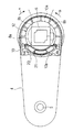
【図2】上カバーの一部を破断して示す第2アームの上面図
【図3】第2アームが原点位置にある状態(a)、及び第1アームに対して回転した状態(b)を下カバーを外して示す底面図
【図4】ロボット本体の外観を示す正面図
【図5】外側ケーブルガイドに内側ケーブルホルダが保持された状態の斜視図(a)及び縦断面図(b)
【符号の説明】
図面中、1はロボット本体、3は第1アーム(第1のアーム)、4は第2アーム(第2のアーム)、7はケーブル、8はフレーム、8aは連結部、8bはくびれ部、10はフレーム、10bは配線挿通孔、12は減速機ユニット、13は軸受、20は外側ケーブルガイド、20aはスライド溝部、21は内側ケーブルホルダ、21aはスライド突部を示す。[0001]
BACKGROUND OF THE INVENTION
According to the present invention, the second arm frame is rotatably connected to the first arm frame via the shaft portion, and the cable passage is located on the outer peripheral side of the shaft portion to the second arm frame. The present invention relates to a joint structure of a robot in which a wiring insertion hole is provided.
[0002]
[Problems to be solved by the invention]
For example, in an articulated robot in which a plurality of arms are rotatably connected in sequence, wiring (cable) is passed through the arm. For example, in a small horizontal articulated robot, in the joint portion of the first arm and the second arm, the frame of the second arm is rotatably connected to the frame of the first arm. A cable (wiring) is passed through an insertion hole formed in the frame of the arm.
[0003]
In this case, the insertion hole extends in an arc shape in the circumferential direction in order to prevent the cable from being sandwiched between the frames of the first arm and eventually disconnected as the second arm rotates relative to the first arm. As a long hole shape, it is considered that the cable can move relatively in the insertion hole. In this case, the rotation range of the second arm with respect to the first arm is restricted in terms of software and hardware, but the cable passes through the insertion hole as a long hole. By being able to move, a relatively wide rotation range can be secured.
[0004]
However, even if the insertion hole is a long hole as described above, the cable is not caught, but when the second arm rotates to the position where the insertion hole wraps around the frame of the first arm when viewed in the axial direction, the cable May directly contact the frame of the first arm made of metal (casting), so that there is still a possibility that the cable may be rubbed to damage the coating or to be broken if it gets worse.
[0005]
The present invention has been made in view of the above circumstances, and an object thereof is to provide a wiring insertion hole that is located on the outer peripheral side of the shaft portion and serves as a cable passage, and the cable is provided in the frame of the arm. It is an object of the present invention to provide a joint structure of a robot that can prevent direct contact and protect a cable.
[0006]
[Means for Solving the Problems]
In order to achieve the above object, the joint structure of the robot according to the present invention has a wiring insertion hole provided in the frame of the second arm formed in a long hole shape extending in the circumferential direction, and the cable is inserted into the wiring. The inside of the hole is provided in a state of being held by an inner cable holder that is slidably movable in the circumferential direction, and the inner cable holder is moved to the first arm according to relative rotation of the second arm with respect to the first arm. It is comprised so that it may contact | abut to this flame | frame (invention of Claim 1).
[0007]
According to this, when the cable is passed through the wiring insertion hole while being held by the inner cable holder, the second arm rotates to a position where the wiring insertion hole wraps on the frame of the first arm. Even so, the cable can be prevented from coming into direct contact with the frame of the first arm only by the inner cable holder abutting against the frame of the first arm. Further, even when the inner cable holder abuts against the frame of the first arm, the second inner cable holder relatively slides in the elongated hole insertion hole while holding the cable. The required rotation range of the first arm relative to the first arm can be ensured.
[0008]
Therefore, according to the joint structure of the robot of the first aspect, the cable is prevented from coming into direct contact with the frame of the first arm while ensuring the function required for the wiring insertion hole, thereby protecting the cable. In addition, a simple configuration in which only an inner cable holder is provided can be achieved. The first arm referred to in the present invention means one arm, the second arm means another arm that is rotationally connected to the arm, and a specific position in the entire robot arm. Of course, it does not indicate the arm of the order.
[0009]
In this case, the wiring insertion hole is provided with an outer cable guide formed in a cylindrical shape that is curved in an arc shape from the plastic in the extending direction of the wiring insertion hole, and the plastic inner cable holder is provided in the outer cable guide. Can be slidably supported (invention of claim 2). According to this, since the sliding movement is performed by sliding between the plastic members, the sliding movement of the inner cable holder is smoothly performed.
[0010]
DETAILED DESCRIPTION OF THE INVENTION
Hereinafter, an embodiment in which the present invention is applied to a small horizontal articulated (four-axis) robot will be described with reference to the drawings. FIG. 4 shows the external configuration of the main body 1 of the horizontal articulated robot in the present embodiment in a state where it is at the origin position. First, the entire configuration of the robot main body 1 will be briefly described.
[0011]
That is, on the
[0012]
Although not shown in detail, a single-axis servomotor for rotating the
[0013]
Further, a robot controller (not shown) is connected to the robot body 1 (base 2), and the motors are controlled by the robot controller. Accordingly, in the robot body 1, as shown only in part in FIG. 1, a cable (wiring) 7 is passed from the
[0014]
Next, FIG. 1 and FIG. 2 show the configuration of the joint portion that connects the
[0015]
First, as shown in FIG. 1, the
[0016]
On the other hand, the outer arm of the
[0017]
The
[0018]
At this time, the
[0019]
The
[0020]
The robot controller is provided with a so-called soft limit that restricts the rotation range of the
[0021]
As shown in FIGS. 1 to 3, the
[0022]
In this embodiment, an
[0023]
On the other hand, the
[0024]
As shown in FIG. 1 and the like, the
[0025]
Thus, as will be described in the following description of the operation, the
[0026]
Next, the operation of the above configuration will be described. In the joint structure that connects the
[0027]
Now, for example, when the
[0028]
When the
[0029]
Therefore, if the
[0030]
Although illustration and description are omitted, the same effect can be obtained when the
[0031]
As described above, according to the joint structure of the robot of this embodiment, the
[0032]
In the above embodiment, the present invention is applied to a horizontal articulated robot, but the present invention can be applied not only to a vertical articulated robot but also to robots of various structures. In this case, the first arm and the second arm referred to in the present invention mean one arm and another arm that is rotationally connected to the arm, such as a specific position in the entire robot arm, Of course, it does not indicate an arm of order. In addition, the present invention is within the scope not departing from the gist of the invention, such as the shape of the robot arm (frame), the arrangement of the servo motor, and the detailed configuration such as the configuration of the bearing and the speed reducer. It can be implemented with appropriate changes.
[Brief description of the drawings]
FIG. 1 shows an embodiment of the present invention, and is a longitudinal front view showing the structure of a joint portion of a connecting portion between a first arm and a second arm. FIG. 2 is a partially cutaway view of an upper cover. FIG. 3 is a bottom view showing a state in which the second arm is at the origin position (a) and a state in which the second arm is rotated with respect to the first arm (b) with the lower cover removed. FIG. 5 is a perspective view (a) and a longitudinal cross-sectional view (b) of the state where the inner cable holder is held by the outer cable guide.
[Explanation of symbols]
In the drawings, 1 is a robot body, 3 is a first arm (first arm), 4 is a second arm (second arm), 7 is a cable, 8 is a frame, 8a is a connecting portion, 8b is a constricted portion, 10 is a frame, 10b is a wiring insertion hole, 12 is a reduction gear unit, 13 is a bearing, 20 is an outer cable guide, 20a is a slide groove, 21 is an inner cable holder, and 21a is a slide protrusion.
Claims (2)
前記配線挿通孔が周方向に延びる長孔状に形成されていると共に、
前記ケーブルは、前記配線挿通孔の内部を周方向にスライド移動自在に設けられ前記第2のアームの前記第1のアームに対する相対回転に応じて該第1のアームのフレームに当接する内側ケーブルホルダに保持された状態で設けられていることを特徴とするロボットの関節部構造。A frame of the second arm is rotatably connected to the frame of the first arm via a shaft portion, and is located on the outer peripheral side of the shaft portion and serves as a cable passage to the frame of the second arm. It is a joint structure of a robot in which a wiring insertion hole is provided,
The wiring insertion hole is formed in a long hole shape extending in the circumferential direction,
The cable is provided so as to be slidable in the circumferential direction inside the wiring insertion hole, and is in contact with the frame of the first arm according to relative rotation of the second arm with respect to the first arm. A joint structure of a robot, characterized in that it is provided in a state where it is held by a robot.
Priority Applications (1)
| Application Number | Priority Date | Filing Date | Title |
|---|---|---|---|
| JP2002023856A JP3801059B2 (en) | 2002-01-31 | 2002-01-31 | Robot joint structure |
Applications Claiming Priority (1)
| Application Number | Priority Date | Filing Date | Title |
|---|---|---|---|
| JP2002023856A JP3801059B2 (en) | 2002-01-31 | 2002-01-31 | Robot joint structure |
Publications (2)
| Publication Number | Publication Date |
|---|---|
| JP2003225883A JP2003225883A (en) | 2003-08-12 |
| JP3801059B2 true JP3801059B2 (en) | 2006-07-26 |
Family
ID=27746453
Family Applications (1)
| Application Number | Title | Priority Date | Filing Date |
|---|---|---|---|
| JP2002023856A Expired - Lifetime JP3801059B2 (en) | 2002-01-31 | 2002-01-31 | Robot joint structure |
Country Status (1)
| Country | Link |
|---|---|
| JP (1) | JP3801059B2 (en) |
Cited By (1)
| Publication number | Priority date | Publication date | Assignee | Title |
|---|---|---|---|---|
| JP2011064265A (en) * | 2009-09-17 | 2011-03-31 | Denso Wave Inc | Mounting structure of reduction gear, and method for manufacturing reduction gear |
Families Citing this family (10)
| Publication number | Priority date | Publication date | Assignee | Title |
|---|---|---|---|---|
| JPS5990893A (en) * | 1982-11-16 | 1984-05-25 | 松下電器産業株式会社 | Music reproducer with indication of name of music selected freely |
| CN103237634B (en) * | 2010-10-08 | 2016-12-14 | 布鲁克斯自动化公司 | The vacuum robot of Driven by Coaxial |
| JP2013006238A (en) * | 2011-06-24 | 2013-01-10 | Seiko Epson Corp | Horizontal articulated robot |
| JP5915005B2 (en) * | 2011-06-24 | 2016-05-11 | セイコーエプソン株式会社 | Horizontal articulated robot |
| JP5966532B2 (en) * | 2012-04-02 | 2016-08-10 | セイコーエプソン株式会社 | robot |
| CN105452989B (en) * | 2013-08-02 | 2018-09-11 | 国立大学法人东京工业大学 | Interface arrangement |
| JP2013223923A (en) * | 2013-08-06 | 2013-10-31 | Seiko Epson Corp | Horizontal articulated robot |
| JP6135562B2 (en) * | 2014-03-14 | 2017-05-31 | トヨタ自動車株式会社 | Joint structure of humanoid robot |
| JP6054932B2 (en) | 2014-10-14 | 2016-12-27 | ファナック株式会社 | Joint structure capable of optimizing the length margin of the striatum, and industrial robot equipped with the joint structure |
| KR102525041B1 (en) * | 2018-08-06 | 2023-04-24 | 삼성전자주식회사 | Cable guide device for multi-articular joint robot |
-
2002
- 2002-01-31 JP JP2002023856A patent/JP3801059B2/en not_active Expired - Lifetime
Cited By (1)
| Publication number | Priority date | Publication date | Assignee | Title |
|---|---|---|---|---|
| JP2011064265A (en) * | 2009-09-17 | 2011-03-31 | Denso Wave Inc | Mounting structure of reduction gear, and method for manufacturing reduction gear |
Also Published As
| Publication number | Publication date |
|---|---|
| JP2003225883A (en) | 2003-08-12 |
Similar Documents
| Publication | Publication Date | Title |
|---|---|---|
| JP3801059B2 (en) | Robot joint structure | |
| JP3952955B2 (en) | Articulated robot | |
| JP6846394B2 (en) | Cable guide with multi-axis angle adjustment link | |
| JP4822061B2 (en) | Double arm robot | |
| JP5457922B2 (en) | Industrial robot | |
| JP4614878B2 (en) | Finger unit of robot hand and assembling method | |
| JP5552329B2 (en) | Welding robot | |
| JP4315720B2 (en) | Cable guides for joints such as robots | |
| KR20130025340A (en) | Robot | |
| CN210422286U (en) | Vehicle door opening and closing apparatus | |
| US5816107A (en) | Joint for industrial robot | |
| JP5891018B2 (en) | Industrial robot and cable placement method for industrial robot | |
| KR101086295B1 (en) | Articulated robot | |
| JP4131086B2 (en) | Robot joint structure | |
| JP5670588B2 (en) | Articulated robot | |
| JP2539796B2 (en) | Articulated robot | |
| WO2020136890A1 (en) | Multijoint robot | |
| JPH0443743B2 (en) | ||
| JP3298411B2 (en) | Robot and robot control method | |
| JP2008023680A (en) | Robot arm bracket and robot arm | |
| CN110355781B (en) | Wrist structure of robot | |
| JPH02152788A (en) | Industrial robot | |
| JPH07328982A (en) | Wiring/piping structure for articulated robot | |
| JP2620911B2 (en) | Industrial robot | |
| JP2704198B2 (en) | Industrial robot |
Legal Events
| Date | Code | Title | Description |
|---|---|---|---|
| A621 | Written request for application examination |
Free format text: JAPANESE INTERMEDIATE CODE: A621 Effective date: 20040412 |
|
| A977 | Report on retrieval |
Free format text: JAPANESE INTERMEDIATE CODE: A971007 Effective date: 20060308 |
|
| TRDD | Decision of grant or rejection written | ||
| A01 | Written decision to grant a patent or to grant a registration (utility model) |
Free format text: JAPANESE INTERMEDIATE CODE: A01 Effective date: 20060411 |
|
| A61 | First payment of annual fees (during grant procedure) |
Free format text: JAPANESE INTERMEDIATE CODE: A61 Effective date: 20060424 |
|
| R150 | Certificate of patent or registration of utility model |
Free format text: JAPANESE INTERMEDIATE CODE: R150 Ref document number: 3801059 Country of ref document: JP Free format text: JAPANESE INTERMEDIATE CODE: R150 |
|
| FPAY | Renewal fee payment (event date is renewal date of database) |
Free format text: PAYMENT UNTIL: 20090512 Year of fee payment: 3 |
|
| FPAY | Renewal fee payment (event date is renewal date of database) |
Free format text: PAYMENT UNTIL: 20120512 Year of fee payment: 6 |
|
| R250 | Receipt of annual fees |
Free format text: JAPANESE INTERMEDIATE CODE: R250 |
|
| FPAY | Renewal fee payment (event date is renewal date of database) |
Free format text: PAYMENT UNTIL: 20120512 Year of fee payment: 6 |
|
| S531 | Written request for registration of change of domicile |
Free format text: JAPANESE INTERMEDIATE CODE: R313531 |
|
| FPAY | Renewal fee payment (event date is renewal date of database) |
Free format text: PAYMENT UNTIL: 20130512 Year of fee payment: 7 |
|
| R350 | Written notification of registration of transfer |
Free format text: JAPANESE INTERMEDIATE CODE: R350 |
|
| FPAY | Renewal fee payment (event date is renewal date of database) |
Free format text: PAYMENT UNTIL: 20130512 Year of fee payment: 7 |
|
| FPAY | Renewal fee payment (event date is renewal date of database) |
Free format text: PAYMENT UNTIL: 20130512 Year of fee payment: 7 |
|
| FPAY | Renewal fee payment (event date is renewal date of database) |
Free format text: PAYMENT UNTIL: 20140512 Year of fee payment: 8 |
|
| R250 | Receipt of annual fees |
Free format text: JAPANESE INTERMEDIATE CODE: R250 |
|
| R250 | Receipt of annual fees |
Free format text: JAPANESE INTERMEDIATE CODE: R250 |
|
| R250 | Receipt of annual fees |
Free format text: JAPANESE INTERMEDIATE CODE: R250 |
|
| R250 | Receipt of annual fees |
Free format text: JAPANESE INTERMEDIATE CODE: R250 |
|
| R250 | Receipt of annual fees |
Free format text: JAPANESE INTERMEDIATE CODE: R250 |
|
| R250 | Receipt of annual fees |
Free format text: JAPANESE INTERMEDIATE CODE: R250 |
|
| R250 | Receipt of annual fees |
Free format text: JAPANESE INTERMEDIATE CODE: R250 |
|
| R250 | Receipt of annual fees |
Free format text: JAPANESE INTERMEDIATE CODE: R250 |
|
| R250 | Receipt of annual fees |
Free format text: JAPANESE INTERMEDIATE CODE: R250 |
|
| EXPY | Cancellation because of completion of term |