【0001】
【発明の属する技術分野】
本発明は、金属板を加熱して曲げ加工するための金属板の曲げ加工方法及び装置に関するものである。
【0002】
【従来の技術】
従来から金属板を加熱して曲げ加工するものが特開昭55−130339号公報や特開昭62−93028号公報等により知られている。
【0003】
特開昭55−130339号公報に示された従来例は、金属板の折り曲げ部に逆プラズマを発生させ、金属板の折り曲げ部に所望の熱歪みを発生させて金属板を加工するものである。そして、この従来例にあっては、電極を金属板に対して所定の距離離した状態でプラズマアークを発生させるようにしているので、金属板の材質や厚み等が代わったり、あるいは電流値の変化等があると、プラズマアークを発生させるために電極の位置をその度に位置調整し直す必要があり、電極の位置調整がきわめて面倒であり、このため、大型の金属板の曲げ加工は対応できるが、微小な曲げ加工には適していないという問題があった。
【0004】
また、特開昭62−93028号公報に示された従来例は、金属板のレーザービームを照射して金属板の折り曲げ加工部に所望の熱歪みを発生させて金属板を加工するものである。この従来例にあっては、金属板の材質や厚み等の材料条件に応じてレーザーの波長を変える必要があり、同一条件での制御が困難であるとう問題がある。
【0005】
【発明が解決しようとする課題】
本発明は上記の点に鑑みてなされたものであり、簡単な方法及び装置で確実に放電をして金属板の曲げ加工ができ、また、微小な曲げ加工であっても容易に行うことができる金属板の曲げ加工方法及び装置を提供することを課題とするものである。
【0006】
【課題を解決するための手段】
上記課題を解決するために本発明に係る金属板の曲げ加工方法は、電源1と曲げ対象の金属板2に放電を発生させる電極3からなる装置により金属板2の折り曲げ部に所望の熱歪みを発生させて金属板2を曲げ加工するに当たり、電極3を金属板2に接近させ、電極3と金属板2との間隔を変化させる過程で放電を発生させることを特徴とするものである。このような方法を採用することで、電極3を移動させて電極3と金属板2との間隔を変化させる過程で放電を発生させて金属板2の折り曲げ部に所望の熱歪みを発生させて金属板2を曲げ加工することができ、金属板2の材質や厚み等が異なっても電極3を移動させる過程で確実に放電を発生させて目的とする曲げ加工ができるものである。
【0007】
また、接近させた電極3を金属板2に接触させ、次に電極3を金属板2よりかい離することにより放電を発生させることが好ましい。このような方法を採用することで、短い移動距離で確実に放電を発生させて目的とする曲げ加工ができるものである。
【0008】
また、接近させた電極3を金属板2に近づける過程で放電を発生させることが好ましい。このような方法を採用することで、電極3を金属板2からかい離する過程で放電を発生させる場合に比べて、電極3を金属板2に近づける過程で放電を発生させると電極3と金属板2との間隔の距離が長いところで放電が発生し、これにより金属板2への熱影響を抑えることができるものである。
【0009】
また、電極3と金属板2との間隔を変化させる過程で放電を発生させることを複数回繰り返すことが好ましい。このような方法を採用することで、放電を確実に繰り返し発生させることができて目的とする曲げ加工ができるものである。
【0010】
また、電極3に電磁石4を取付け、電磁石4により電極3を移動させて電極3と金属板2との間隔を変化させる過程で放電を発生させて金属板2の折り曲げ部に所望の熱歪みを発生させて金属板2を曲げ加工することが好ましい。このような方法を採用することで、電磁石4により電極3の移動を制御できる。
【0011】
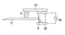
また、電極3に磁石を有するシャフト21を設け、シャフト21を電磁石4に対向させ、シャフト21の電磁石4に対向する部分に+又は−の極性を持たせ、電磁石4に交流電圧35を印加させてシャフト21を吸引したり反発させたりすることで電極3と金属板2との間隔を変化させる動作を繰り返し行い、電極3と金属板2との間隔を変化させる過程で放電を発生させて金属板2の折り曲げ部に所望の熱歪みを発生させることを繰り返して金属板2を曲げ加工することが好ましい。このような方法を採用することで、電磁石4に交流電圧を印加させて電極3の金属板2に接近する方向の移動及び金属板2からかい離する方向の移動の繰り返しが行えるものである。
【0012】
また、電極3に電磁石4を取付け、電磁石4により電極3を移動させて電極3と金属板2との間隔を変化させる過程で放電を発生させて金属板2の折り曲げ部に所望の熱歪みを発生させて金属板2を曲げ加工するに当たり、電極3の電磁石4に印加する電圧の周波数を変えることで、対象部位ごとに電極3のかい離回数を制御して金属板2の折り曲げ部の対象部位ごとに所望の熱歪みを発生させることを繰り返して金属板2を曲げ加工することが好ましい。このような方法を採用することで、電極3の金属板2に接近する方向の移動及び金属板2からかい離する方向の移動の繰り返しの周期を変えることができて、対象部位毎に最適の加工ができる。
【0013】
また、電極3に圧電アクチュエータ5を設けて電極3を移動させて電極3と金属板2との間隔を変化させる過程で放電を発生させて金属板2の折り曲げ部に所望の熱歪みを発生させて金属板2を曲げ加工することが好ましい。このような方法を採用することで、電極3の金属板2に接近する方向の移動及び金属板2からかい離する方向の移動を圧電アクチュエータ5を用いて実現できるものである。
【0014】
また、電極3を移動させて電極3と金属板2との間隔を変化させる過程で放電を発生させて金属板2の折り曲げ部に所望の熱歪みを発生させて金属板2を曲げ加工するに当たって、電極3と金属板2との間隔を変化させる際の電極3の移動速度を制御するという簡単な方法で金属板2の曲げ角度を制御することができるものである。
【0015】
また、電源1の電圧を制御することにより、金属板2の曲げ角度を制御することが好ましい。このような方法を採用することで、電源1の電圧を変えるという簡単な方法で金属板2の曲げ角度を制御することができるものである。
【0016】
また、電源1からの電荷を充電するためのコンデンサ6と、コンデンサ6に充電した電荷を電極3と金属板2との間に放電させるための手段とを備え、電極3を移動させて電極3と金属板2との間隔を変化させる過程でコンデンサ6に充電した電荷を瞬間的に放電させて金属板2の折り曲げ部に所望の熱歪みを発生させて金属板2を曲げ加工することが好ましい。このような方法を採用することで、瞬間的に大電流を放電できて確実に放電を発生させることができるものである。
【0017】
また、電源1と電極3との間又は電源1と金属板2との間にコイル7を設け、電極3を移動させて電極3と金属板2との間隔を変化させるときにコイル7が発生する誘導起電力を利用して放電を発生させて金属板2の折り曲げ部に所望の熱歪みを発生させて金属板2を曲げ加工することがこのましい。このような方法を採用することで、電極3をかい離するときにコイル7が発生する誘導起電力を利用して放電を発生させることができるものである。
【0018】
また、金属板2の曲げ加工計測手段により金属板2の曲げ状態を計測することが好ましい。このような方法を採用することで、金属板2の加工、曲げ状態の計測を繰り返して目的とする曲げ加工ができるものである。
【0019】
また、放電により折り曲げられた金属板2の折り曲げ線から電極3を折り曲げ線と直交する水平方向に任意の距離移動してその水平方向の距離を求めると共に、該水平方向に移動した位置で電極3を下降させて曲げられた金属板2に当接させて金属板2の折り曲げ線から電極3までの垂直方向の距離を求め、上記水平方向の距離と垂直方向の距離から金属板2の曲げ角度を計測することが好ましい。このような方法を採用することで、金属板2の曲げ加工に使用する電極3を利用して簡単に金属板2の曲げ角度を計測することができるものである。
【0020】
また、放電により折り曲げられた金属板2の曲げ角度を放電に用いた2個の電極3により求めるものであって、2個の電極3を金属板2の折り曲げ線と直交する水平方向に任意の距離移動して移動後における2個の電極3間の金属板2の折り曲げ方向と直交する水平方向の距離を求めると共に、該水平方向に移動した位置で2個の電極3を下降させて曲げられた金属板2に当接させて2個の電極3間の垂直方向の距離を求め、上記水平方向の距離と垂直方向の距離から金属板2の曲げ角度を計測することが好ましい。このような方法を採用することで、金属板2の曲げ加工に使用する電極3を利用して簡単に金属板2の曲げ角度を計測することができるものである。
【0021】
また、放電により折り曲げられた金属板2の曲げ部にばね圧を計測する手段9を接触させて、接触圧により曲げ状態を計測することが好ましい。このような方法を採用することで、放電により折り曲げられた金属板2の曲げ部のばね圧を計測でき、これにより加工に当たって金属板2の曲げ部が目的とするばね圧を有するようにフィードバック制御することができるものである。
【0022】
また、放電により金属板2を折り曲げるに当たって金属板2の曲げ加工を制御する制御手段を設け、金属板2の複数のねらいの角度に対する制御手段の制御量の関係のデータを収集して、その関係から制御量と曲げ角度との関係式を算出し、このようにして算出した制御量と曲げ角度との関係式に基づいて目的とする曲げ角度となるように制御量を制御することが好ましい。このような方法を採用することで、金属板2を放電で曲げ加工するに当たっての初期調整の精度を向上することができるものである。
【0023】
また、金属板2の複数のねらいの角度に対する制御手段の制御量の関係のデータを収集して、その関係から制御量と曲げ角度との関係式を算出し、同様にして更に制御量と曲げ角度との関係式を複数求め、上記のようにして複数の異なる関係式を求めた後に、1回目の曲げ加工を行って曲げ角度と制御量とを求めて上記複数種類の関係式のうち最も近い関係式を選択し、2回目以降の曲げ加工において選択した関係式に基づいて制御量を決定することが好ましい。このような方法を採用することで、金属板2のばらつきに応じて最適の制御量と曲げ角度との関係式を選択して制御することができるものである。
【0024】
また、金属板2の複数のねらいの角度に対する制御手段の制御量の関係のデータを収集して、その関係から制御量と曲げ角度との関係式を算出し、同様にして更に制御量と曲げ角度との関係式を複数求め、上記のようにして複数の異なる関係式を求めた後に、金属板2の1次曲げ加工を行って曲げ角度と制御量とを求めて上記複数種類の関係式のうち最も近い関係式を選択し、目的とする曲げ角度と上記1次曲げ加工による曲げ角度との差を求め、上記選択された関係式に基づき上記角度の差に対応する制御量を算出し、このようにして算出した制御量となるように制御して2次曲げ加工をして曲げ角度の調整を行うことが好ましい。このような方法を採用することで、目的とする角度への調整が容易に行えるものである。
【0025】
また、金属板2の複数のねらいの角度に対する制御手段の制御量の関係のデータを収集して、その関係から制御量と曲げ角度との関係式を算出し、このようにして算出した制御量と曲げ角度との関係式に基づいて目的とする曲げ角度となるように制御量を制御し、上記制御量により1〜Nの金属板2の曲げ加工を行い、1〜Nの金属板2の曲げ角度と制御量との関係のデータをもとに制御量と曲げ角度との次の関係式を算出し、このようにして算出した制御量と曲げ角度との次の関係式に基づいて目的とする曲げ角度となるように制御量を制御することが好ましい。このような方法を採用することで、金属板の製造におけるロット変動や電極3の消耗などの外乱の変化に応じて調整データの最適化が図れるものである。
【0026】
また、金属板2の曲げ加工を内部を不活性ガス雰囲気としたチャンバー11内において行うことが好ましい。このような方法を採用することで、金属板2の酸化の影響を抑えることができるものである。
【0027】
また、放電の状態や金属板2の曲げ加工の状態を計測し、計測データに基づいて金属板2の曲げ加工をフィードバック制御手段12により制御することが好ましい。このような方法を採用することで、目的とする曲げ加工が安定して実現できるものである。
【0028】
また、曲げ角度を制御するための放電電流検知手段を設けて放電電流を計測し、この放電電流の計測データに基づいて金属板2の曲げ加工をフィードバック制御手段12により制御することが好ましい。このような方法を採用することで、放電検知手段により放電電流を計測し、この放電電流をもとにフィードバック制御手段12により所定の放電電流となるようにフィードバック制御して目的とする曲げ加工ができるものである。
【0029】
また、金属板2の表面温度を計測し、この金属板2の表面温度の計測データに基づいて金属板2の曲げ加工をフィードバック制御手段12により制御することが好ましい。このような方法を採用することで、金属板2の表面温度の検出値と正常値に対する差をモニタリングして放電電圧を制御する等のフィードバック制御を行って目的とする曲げ加工ができるものである。
【0030】
また、電極3を電極位置制御装置13により位置制御することが好ましい。このような方法を採用することで、電極位置制御装置13により電極3を金属板2に対して移動することができるものである。
【0031】
また、複数回曲げ調整を行うに当たり、毎回電極3の位置を微小に移動させることが好ましい。このような方法を採用することで、複数回曲げ調整を行う場合、毎回微小に電極3の位置を移動させて放電して金属板2の曲げ加工をすることで金属板2の表面の熱影響を抑えることができるものである。
【0032】
また、金属板2の曲げ加工において曲げ角度が同じで変位量が異なるものに対して、電極3の位置を横方向に変化させることで同じ曲げ角度で異なる変位量の曲げ加工を行うことが好ましい。このような方法を採用することで、金属板2の曲げ加工において同じ曲げ角度でも電極3の位置を変化させることで異なる変位量に加工できるものである。
【0033】
また、金属板2の折り曲げ線上に電極3を複数並べることが好ましい。このような方法を採用することで、電極3を折り曲げ線に沿ってを移動させることなく、又は移動量を少なくして一度に又は少ない移動量で容易に金属板2の曲げ加工ができるものである。
【0034】
また、金属板2の折り曲げ線上に複数並べた電極3と並行して変位センサ14を配置して金属板2のねじれ状態を監視することが好ましい。このような方法を採用することで、折り曲げ線上に複数並べた電極3により金属板2を折り曲げる際折り曲げ線に沿った各部における曲げ角度が不均一になってねじれ状態が発生した場合、このねじれを変位センサ14により検出して均一な曲げ角度となるように制御することができるものである。
【0035】
また、電極3を金属板2の2箇所以上に配置して複数の電極3の動作のタイミングをずらすことが好ましい。このように複数の電極3の動作のタイミングをずらすことで金属板2を複雑な形状に曲げ加工することができるものである。
【0036】
また、電極3を金属板2の表面側と裏面側とにそれぞれ配置して表裏いずれかの電極3と金属板2との間に放電を発生させるかを選択して金属板2を曲げ加工することが好ましい。このような方法を採用することで、金属板2を表側又は裏側に曲げ加工でき、また、曲げ角度の曲げすぎなどに対しては反対方向の電極3を用いて放電を発生させて曲げ角度の調整ができるものである。
【0037】
また、金属板2の折り曲げ線上に電極3を複数回打点を繰り返しながらスキャンさせることが好ましい。このような方法を採用することで、幅を持った金属板2の曲げ加工が1つの電極3で可能である。
【0038】
また、金属板2の折り曲げ線上に電極3を複数回スキャンさせるに当たって、始めは曲げ量が大きくなるように制御し、スキャン回数が増すにつれ曲げ角度が小さくなるように制御することが好ましい。このような方法を採用することで、精密な曲げ加工ができるものである。
【0039】
また、金属板2の折り曲げ線に並行して設けた測定ラインの上に複数の変位センサ14を配置して、曲げによる測定ライン位置の変位を測定し、金属板2の両側の曲げ角度が均一になるように、電極スキャン位置に対応して曲げ加工条件を制御することが好ましい。このような方法を採用することで、電極3をスキャンしながら金属板2の曲げ加工を行う際に、電極3のかい離の回数や放電の電圧を制御することにより、始点と終点の曲げ角度を均一にしてねじれを無くすことができるものである。
【0040】
また、本発明の金属板の曲げ加工装置は、電源1と曲げ対象の金属板2に放電を発生させる電極3とを備えて金属板2の折り曲げ部に所望の熱歪みを発生させて金属板2を曲げ加工する金属板2の曲げ加工装置であって、該装置に、電極3と金属板2との間隔を変化させる過程で放電を発生させるように電極3を金属板2に対して移動させるための電極移動手段10と、金属板2の曲げ加工後の曲げ角度を計測する金属板2の曲げ角度計測手段16と、曲げ角度計測手段16により計測した曲げ角度と目的とする曲げ角度との差に基づいて、金属板2の曲げ加工部が目的とする曲げ角度となるように曲げ加工条件を制御するための制御手段19とを設けて成ることをを特徴とするものである。このような構成とすることで、電極3を金属板2に対して移動させながら放電を発生させて金属板2を曲げ加工でき、しかも、曲げ角度計測手段16により計測した曲げ角度と目的とする曲げ角度との差に基づいて、制御手段19によりフィードバック制御をして目的とする曲げ角度に加工できるものである。
【0041】
また、電源1と曲げ対象の金属板2に放電を発生させる電極3とを備えて金属板2の折り曲げ部に所望の熱歪みを発生させて金属板2を曲げ加工する金属板2の曲げ加工装置であって、該装置に、電極3と金属板2との間隔を変化させる過程で放電を発生させるように電極3を金属板2に対して移動させるための電極移動手段10と、金属板2の曲げ加工後における曲げ加工部の結果を特性として計測する計測手段20と、計測手段20により計測した曲げ加工部のデータに基づいて曲げ加工部の特性が目的とする曲げ特性となるように曲げ加工条件を制御するための制御手段19とを設けることを特徴とするものであってもよい。このような構成とすることで、電極3を金属板2に対して移動させながら放電を発生させて金属板2を曲げ加工でき、しかも、計測手段20により検出した曲げ加工部のデータに基づいて制御手段19によりフィードバック制御をして曲げ加工部が目的とする特性となるように曲げ加工できるものである。
【0042】
【発明の実施の形態】
以下、本発明を添付図面に示す実施形態に基づいて説明する。
【0043】
図1には本発明の金属板の曲げ加工方法の基本的な概略構成図が示してある。図中1は電源であり、電源1の一端に電極3が接続してあり、電源1の他端に曲げ対象である金属板2が接続してあり、電源1と曲げ対象の金属板2に放電を発生させ、金属板2の折り曲げ部に所望の熱歪みを発生させて金属板2を曲げ加工するようになっている。
【0044】
ここで、本発明においては、電極3を金属板2に接近させ、電極3を電極移動手段10により移動させて電極3と金属板2との間隔を変化させる過程で放電を発生させるようにしている。このように電極3を移動させて電極3と金属板2との間隔を変化させる過程で放電を発生させるので、曲げ対象である金属板2の材質や厚み等が異なったり、電源1の電圧が異なっても電極3を移動させる過程で曲げ対象である金属板2と電極3との間で放電が確実に発生し、金属板2の折り曲げ部に所望の熱歪みを発生させて金属板2を曲げ加工することができるのである。
【0045】
以下図2に基づいて、電極3を移動させて電極3と金属板2との間隔を変化させる過程で放電を発生させることで金属板2の折り曲げ部に所望の熱歪みを発生させて金属板2を曲げ加工する原理を説明する。図2(a)は放電前の状態、図2(b)は放電中の状態、図2(c)は放電後の状態を示している。図2(a)の放電前の状態から図2(b)の矢印のように電極3を移動させていって電極3と金属板2との間隔を変化させていくと金属板2と電極3との間隔が最適の距離になると最適な放電が発生する。このように放電が発生すると、金属板2の表面(放電が発生する側)と裏面の温度差による温度勾配が生じ、この温度勾配による塑性変形がおこる。つまり、放電中は金属板2の表面側は熱膨張に伴う引っ張り力が作用しており、図2(b)のように表面側が伸びるように曲がり、この時温度の低い裏面側では上記表面側の引っ張り力で裏面側も伸びるように塑性変形している。そして、放電後に温度低下すると表面側が温度低下により収縮して元の状態に戻るが、裏面側は上記の塑性変形した変形量が残存しており、結果として図2(c)のように裏面側が伸びた曲げ状態となるものである。
【0046】
なお、図2に示す説明では放電前の図2(a)の状態で電極3が金属板2に接触しており、図2(b)の状態では矢印のように電極3が金属板2からかい離する方向に移動する過程で放電を発生させる例で説明しているが、接近させた電極3を金属板2に近づける過程で放電を発生させる場合も上記と同様の原理により金属板2の曲げ加工ができるものである。
【0047】
上記のように、本発明においては電極3を移動させて電極3と金属板2との間隔を変化させる過程で放電を発生させるに当たり、金属板2に接触させ、次に電極3を金属板2よりかい離することにより放電を発生させる場合と、電極3を金属板2に近づける過程で放電を発生させる場合とがある。
【0048】
図3には電極3を金属板2に接触させ、次に電極3を金属板2よりかい離することにより放電を発生させる例が示してある。すなわち、電極3を金属板2に接触させ、その後電極3を図3矢印方向に移動することで放電を発生させて金属板2の折り曲げ部に所望の熱歪みを発生させて金属板2を曲げ加工するのである。このように電極3を金属板2に接触した状態からかい離することで電極3の短い移動距離で確実に放電を発生させて金属板2の曲げ加工ができるものである。ここで、電極3の先端の断面積を小さくして金属板2との接触面積をできるだけ小さくすることにより、放電の発生は電極3の形状に支配されるために局所的となり、局所的に放電を発生させて小さな曲げ加工を実現できるものである。
【0049】
図4には接近させた電極3を金属板2に近づける過程で放電を発生させる例が示してある。すなわち、電極3を図4矢印方向(つまり金属板2に近づける方向)に移動する過程で放電を発生させて金属板2の折り曲げ部に所望の熱歪みを発生させて金属板2を曲げ加工するのである。このように電極3を金属板2に近づける方向に移動して放電を発生させる場合における放電が発生する距離をL1とし(図4(b)に示す)、上記の電極3を金属板2に接触させた後にかい離する方向に移動する場合における放電が発生する距離をL2とする(図4(c)に示す)と、L2<L1となり、このため、図4(b)に示す電極3を金属板2に近づける過程で放電を発生させる本実施形態のものは、図4(c)に示す電極3を金属板2からかい離する過程で放電を発生させる実施形態のものに比べて電極3と金属板2との間隔の距離が長いところで放電が発生し、このため本実施形態のものは金属板2への熱影響を抑えることができるものである。
【0050】
上記のように電極3を移動させて電極3と金属板2との間隔を変化させる過程で放電を発生させて金属板2を曲げ加工するに当たり、電極3と金属板2との間隔を変化させる過程で放電を発生させることを複数回繰り返すことで金属板2の曲げ加工を行うようにしてもよい。すなわち、図5に示すように、電極3に電極移動手段10を設け、電極移動手段10により電極3を移動し、これにより電極3と金属板2との間隔を変化させる過程で放電を発生させることを複数回繰り返すのであり、電極3が金属板2に接触した状態から図5の矢印のように電極3を金属板2からかい離させ、更に、この接触とかい離を複数回繰り返して放電を繰り返すのである。
【0051】
図6には電極移動手段10の一例が示してある。すなわち図6には電極3に磁性体よりなるシャフト21を設け、該シャフト21を電磁石4に対向してあり、図6(a)のように電磁石4が励磁してなくて電極3が金属板2に接触している状態で、電磁石4に励磁すると図6(b)のように電極3に設けたシャフト21が電磁石4に吸引され電極3を金属板2からかい離させるものであり、このように電磁石4により電極3の移動を制御することで簡便な手段で電極3の移動制御ができるものである。
【0052】
図7には電極移動手段10の他例が示してある。すなわち図7に示すものは電極3に磁石を有するシャフト21を設け、このシャフト21の電磁石4に対向する部分に+又は−の極性を持たせ、電磁石4に交流電圧35を印加させることで、極性を持ったシャフト21の電磁石4に対向する部位が吸引されたり、反発したりすることで、電極3の繰り返し動作(接触とかい離の繰り返し)を行うようになっている。本実施形態においては電磁石4に交流電圧35を印加させるという簡単な方法で、電極3の金属板2に接近する方向の移動及び金属板2からかい離する方向の移動の繰り返しが実現できるものである。
【0053】
ここで、電磁石4に交流電流を印加するに当たって、周波数を変えて交流電流を印加すると電極3の繰り返し動作(接触とかい離の繰り返し)の周期を変えることができるものである。そして、上記のように電極3の電磁石4に印加する電圧の周波数を変えて金属板2の対象部位ごとに電極3のかい離回数を制御することにより対象部位毎に最適の加工ができるものである。
【0054】
図8には電極移動手段10の更に他例が示してある。すなわち図8に示すものは電極3に圧電アクチュエータ5を設けて電極3を移動させて接触とかい離の動作を行わせるようにしている。このように圧電アクチュエータ5用いて電極5を移動させることで、電極3の移動を高精度に制御できるものである。
【0055】
ところで、電極3と金属板2との間隔を変化させる過程で放電を発生させて金属板2を曲げ加工するに当たって、電極3の移動速度を制御することで曲げ角度を制御することができるものである。図9には電極3に電極移動速度制御手段23を設けたものが示してあり、金属板2を目的とする角度に加工するため、電極3をかい離させる速度を変えることで、金属板2の折り曲げ加工部の加熱熱量を制御することができ、これにより金属板2の折り曲げ角度を簡単に目的とする折り曲げ角度に調整することができるのである。
【0056】
図10には曲げ加工するに当たって、電極3と金属板2との間隔を変化させる過程で放電を発生させて金属板2を曲げ加工するに当たって、金属板2の折り曲げ角度を調整するための他の方法が示してあり、本実施形態においては、図10に示すように電源1の電圧を変えることができる電圧変更手段24を設けたもので、電圧変更手段24により電源1の電圧を変更することにより、金属板2の曲げ角度を簡単に目的とする折り曲げ角度に調整することができるのである。
【0057】
上記のように電極3を移動させて電極3と金属板2との間隔を変化させる過程で放電を発生させるに当たり、電源1からの電荷を充電するためのコンデンサ6と、コンデンサ6に充電した電荷を電極3と金属板2との間に放電させるための手段とを備えたものとすると、コンデンサ6に充電した電荷を放電でき、これにより瞬間的に大電流を放電できて確実に放電を発生させることができるものである。すなわち、図11に示すように、電源1と電極3とを接続する配線25aの途中と電源1と金属板2を接続する配線25bの途中とにコンデンサ6の両端部を接続し、電源1とコンデンサ6との間に第1のスイッチ26を設けると共にコンデンサ6と電極3又は金属板2との間に第2のスイッチ27を設けた回路構成とし、第2のスイッチ27をオフにした状態で第1のスイッチ26をオンにしてコンデンサ6に電荷を充電する。充電後、第1のスイッチ26をオフにし、第2のスイッチ27をオンにすると共に電極3を移動させて放電を発生させてコンデンサ6に充電した電荷を瞬間的に放電する。ここで、第2のスイッチ27をオンするタイミングと電極3のかい離を同期させることで、確実に放電を発生させることができるものである。図11(b)には第2のスイッチ27のオン、電極3の上昇移動又は下降移動、放電発生のタイミングを示すタイムチャートである。
【0058】
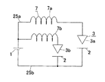
電極3を移動させて電極3と金属板2との間隔を変化させる過程で放電を発生させるに当たり、電源1と電極3との間又は電源1と金属板2との間にコイル7を設け、電極3をかい離するときにコイル7が発生する誘導起電力を利用して放電を発生させるようにしてもよい。図12には電極3を2つ設け、電源1と第1の電極3aとの間に第1のコイル7aを設けるとともに電源1と第2の電極3bとの間に第2のコイル7bを設けた例が示してあり、第1の電極3aを移動(例えば金属板2からかい離)させた時に第1のコイル7aの逆起電力により第1の電極3aと金属板2との間に放電を発生させ、同様に第2の電極3bを移動(例えば金属板2からかい離)させた時に第2のコイル7bの逆起電力により第2の電極3bと金属板2との間に放電を発生させるようになっている。ここで、第1の電極3aと対向する金属板2と、第2の電極3b金属板2とは同一の金属板2であってもよく、あるいは別々の金属板2であってもよい。
【0059】
図13には金属板2の曲げ状態を曲げ加工計測手段により計測する例が示してある。なお、図13においては曲げ状態を計測する曲げ加工計測手段が金属板2の曲げ角度を計測する曲げ角度計測手段8である場合の例が示してある。すなわち、上記した各実施形態のようにして放電を発生させて金属板2の曲げ加工をするに当たって、図13(b)のフローチャートのように放電による曲げ加工、曲げ角度計測手段8による曲げ角度の計測、曲げ角度の判定を行って、曲げ角度の判定が目的の曲げ角度となるまで加工、計測を繰り返し実行することで目的とする曲げ角度になると加工を終了するのである。これにより目的とする曲げ角度に正確に加工することができるものである。
【0060】
図14には曲げ角度計測手段8の一例が示してある。本実施形態においては、放電により折り曲げられた金属板2の折り曲げ線Mから電極3を折り曲げ線Mと直交する水平方向に任意の距離移動してその水平方向の距離L3を求めると共に、該水平方向に移動した位置で電極3を下降させて曲げられた金属板2に当接させて金属板2の折り曲げ線から電極3までの垂直方向の距離L4を求め、上記水平方向の距離L3と垂直方向の距離L4から金属板2の曲げ角度αを計測するのである。すなわち曲げ角度α=arctan(L4/L3)で求めることができる。
【0061】
また、2個以上の電極3を用いて放電を発生させて金属板2の曲げ加工を行うものの場合、図15に示すようにして、放電により折り曲げられた金属板2の曲げ角度を放電に用いた2個の電極3により求めるようにしてもよい。すなわち、図15において2個の電極3を金属板2の折り曲げ線と直交する水平方向に任意の距離移動して移動後における2個の電極3間の金属板2の折り曲げ方向と直交する水平方向の距離L5を求めると共に、該水平方向に移動した位置で2個の電極3を下降させて曲げられた金属板2に当接させて2個の電極3間の垂直方向の距離L6を求め、上記水平方向の距離L5と垂直方向の距離L6から金属板2の曲げ角度αを計測するようにしてもよいものである。この場合も曲げ角度α=arctan(L6/L5)で求めることができる。
【0062】
図16には放電させて折り曲げた金属板2の曲げ部のばね圧により曲げ状態を計測するようにした例が示してある。すなわち本実施形態においては金属板2の曲げ状態の計測をする曲げ加工計測手段としてばね圧を計測する手段9を接触させ、ばね圧を計測する手段9により金属板2の加工した後の曲げ部の接触圧(ばね圧)を計測して曲げ加工の評価をし、接触圧が低下している場合のように目的とするばね圧となっていない場合には、金属板2の曲げ部が目的とする曲げ特性(実施形態では目的とするばね圧)となるように曲げ角度を大きくする等のフィードバック制御することができるものである。
【0063】
次に、電極3を移動させて電極3と金属板2との間隔を変化させる過程で放電を発生させて金属板2を曲げ加工する際に目的とする曲げ加工となるように制御するための曲げ制御方法につき説明する。
【0064】
図17には本発明の曲げ制御方法の一実施形態が示してある。すなわち、本実施形態においては、放電により金属板2を折り曲げるに当たって金属板2の曲げ加工を制御する制御手段を設け、金属板2の複数のねらいの角度(例えば角度α1、角度α2、角度α3……)に対する制御手段の制御量の関係(例えば角度α1、角度α2、角度α3……各々の加工をするための電源1の電圧の制御量や電極3の移動速度の制御等の制御量の関係)のデータを収集し(図17(a))、その関係から図17(b)のように制御量と曲げ角度との関係式y=ax+b又はy=exp(ax+b)を算出する。上記のようにあらかじめ金属板2の複数のねらいの角度(例えば角度α1、角度α2、角度α3……)に対する制御手段の制御量の関係式を求めておき、角度α1となるように金属板2を曲げ加工する場合には上記関係式に基づいて角度α1の加工をするための制御量となるように電源1の電圧を調整したり、電極3の移動速度を調整したりするものである。このようなあらかじめ目標とする折り曲げ角度と制御量との関係式を求めておくことで、金属板2を放電で曲げ加工するに当たっての初期調整の精度を向上することができるものである。
【0065】
ところで金属板2の複数のねらいの角度に対する制御手段の制御量の関係のデータを収集して、その関係から制御量と曲げ角度との関係式を算出する場合、厚み、幅、材質が同一の金属板2を曲げ加工して制御量に対する曲げ角度の関係を何回か調べて、その関係を求めると複数の傾向があることが判る。つまり、上記のように、何度か曲げ角度と制御量との関係式を求めると、図18のように複数の関係式が求められるものであり、そこで、この複数の曲げ角度と制御量との関係式で表される補正曲線1、補正曲線2、補正曲線3……をそれぞれ制御手段に蓄積しておき、金属板2を曲げ加工するに当たって、まず、1回目の曲げ加工を行って曲げ角度と制御量とを求めて上記複数種類の関係式のうち最も近い関係式を選択し、2回目以降の曲げ加工において選択した関係式に基づいて制御量を決定するものである。例えば、1回目の曲げ加工を行った後の曲げ角度と制御量を調べ、その結果が例えば曲げ角度が4、制御量が10の場合は、図18の補正曲線1を選択し、2回目以降の曲げ加工においては選択した関係式(補正曲線1)に基づいて目的とする曲げ角度となるように制御量を決定し、この決定された制御量となるように電源1の電圧の制御や電極3の移動速度の制御等の制御を行うものであり、これにより金属板2のばらつきに応じて最適の制御量と曲げ角度との関係式を選択して制御することができるものである。
【0066】
ところで、上記のようにして、金属板2の複数のねらいの角度に対する制御手段の制御量の関係のデータを収集して、その関係から制御量と曲げ角度との関係式を算出し、同様にして更に制御量と曲げ角度との関係式を複数求め、上記のようにして複数の異なる関係式を求め(つまり図18に示すような複数の補正曲線を求め)た後に、金属板2の1次曲げ加工を行って曲げ角度と制御量とを求めて上記複数種類の関係式のうち最も近い関係式を選択し、目的とする曲げ角度と上記1次曲げ加工による曲げ角度との差を求め、上記選択された関係式に基づき上記角度の差に対応する制御量を算出し、このようにして算出した制御量となるように制御して金属板2の2次曲げ加工をして調整を行うものである。例えば補正曲線1を選んだ場合を例に取ると、目的とする曲げ角度が6°上記第1次曲げ加工による曲げ角度を4°すると、必要曲げ角度=6°−4°=2°であるので、上記必要曲げ角度より制御量を重み付けし、図19に示す補正曲線1にもとづき必要曲げ角度2°に対する制御量2.5を算出し、次に算出した制御量2.5にて曲げ加工位置をわずかにずらして2次曲げ加工を行うことで2回分の曲げ量が加算されて目的とする曲げ角度に加工することができるものである。これにより目的とする角度への調整が容易に行えるものである。図20には本実施形態の制御フローが示してあり、図20の制御フローにおいて、加工重み付けを行って複数の補正曲線から最も近い関係式の補正曲線を選択して曲げ加工(1次曲げ加工)を行うものであり、また、曲げ計測の結果、必要角度となっていない場合には上記のようにして必要角度となるように重み付けして曲げ加工(2次曲げ加工)を行うものである。
【0067】
ところで、前述の図17に示すように金属板2の複数のねらいの角度に対する制御手段の制御量の関係のデータを収集して、その関係から制御量と曲げ角度との関係式を算出し、このようにして算出した制御量と曲げ角度との関係式に基づいて目的とする曲げ角度となるように制御量を制御するに当たり、図21に示すように最初に求めた関係式(図21において補正曲線イで示す)に基づいた目的となる折り曲げ角度となる制御量により1〜Nの金属板2の曲げ加工を行い、この1〜Nの金属板2の曲げ角度と制御量との関係のデータをもとに制御量と曲げ角度との次の関係式を算出し(図21において補正曲線ロで示す)、このようにして算出した制御量と曲げ角度との次の関係式(補正曲線ロ)に基づいてN+1〜2Nの金属板2の加工を行うように補正曲線を更新するものであり、同様にして、補正曲線ロでN+1〜2Nの金属板2の加工をした場合における曲げ角度と制御量との関係のデータをもとに制御量と曲げ角度との更に次の関係式を算出し、このようにして算出した制御量と曲げ角度との更に次の関係式(補正曲線)に基づいて2N+1〜3Nの金属板2の加工を行うように補正曲線を更新するものであり、同様にして次々と新たな補正曲線に更新しながら更新した補正曲線に基づいて加工を行うことで、金属板の製造におけるロット変動や電極3の消耗などの外乱の変化に応じて調整データの最適化が図れるものである。
【0068】
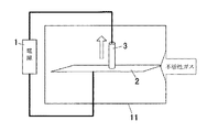
図22には本発明の他の実施形態が示してある。すなわち、本実施形態においては前述の各実施形態のように電極3を金属板2に接近させ、電極3と金属板2との間隔を変化させる過程で放電を発生させて金属板2の曲げ加工を行うに当たり、上記曲げ加工を内部を不活性ガス雰囲気としたチャンバー11内において行うようにしている。このように不活性ガス雰囲気中で放電を発生させて金属板2の曲げ加工を行うことで、金属板2の酸化の影響を抑えることができるものである。
【0069】
図23には電極3を金属板2に接近させ、電極3と金属板2との間隔を変化させる過程で放電を発生させて金属板2の曲げ加工を行うに当たりフィードバック制御手段12を設けてフィードバック制御をするようにした例が示してある。フィードバック制御手段12は放電の状態や金属板2の曲げ加工の状態を計測する手段と、計測手段により計測した計測データに基づいて電源1の電圧や電極3の移動速度等の制御量を調整制御するための制御手段とから構成してある。そして、放電の状態や金属板2の曲げ加工の状態を計測し、計測データに基づいて金属板2の曲げ加工をフィードバック制御手段12により電源1の電圧や電極3の移動速度等の制御量を調整制御をして目的とする曲げ加工が安定して実現するようになっている。
【0070】
図24には放電の状態や金属板2の曲げ加工の状態を計測する手段として放電電流検知手段29を設けてあり、放電電流検知手段29により放電が発生する際の放電電流を計測し、この計測した電流値をもとに目的とする曲げ角度となる電流値となるように制御手段19により電源1の電圧を制御するのである。例えば、目的とする曲げ角度となるように34Aの電流で曲げ加工を行っている際に、放電電流検知手段29により計測した電流値が31Aに低下した場合には、制御手段19により電源1の電圧を上げるようにフィードバック制御するものである。
【0071】
図25には放電の状態や金属板2の曲げ加工の状態を計測する手段として金属板2の表面温度を計測する温度センサ30を設けた例であり、温度センサ30により放電発生時における金属板2の表面温度を計測し、この計測した金属板2の表面温度をもとに、目的とする曲げ角度に加工する場合の正常な表面温度となるように制御手段19により電源1の電圧を制御するのである。
【0072】
図26(a)(b)には電極3をX方向、Y方向、Z方向の各方向に自由に移動させるための電極位置制御装置13を設けた例が示してある。例えばサーボモータやステッピングモータ等の電極位置制御装置13を電極3に取付け、サーボモータやステッピングモータを駆動して電極3を図26(a)(b)のX方向、Y方向、Z方向の各方向に自由に移動させ、金属板2の折り曲げ加工をしたい位置に電極3を移動させたり、あるいは前述の図14や図15のように電極3を用いて曲げ角度の計測を行うために移動させたすることができる。また、Z方向に移動させると、電極3を金属板2に接近させ、電極3と金属板2との間隔を変化させる過程で放電を発生させるようにすることができ、この場合には放電を発生させるための前述の電極移動手段10を電極位置制御装置13により兼用することもできるものである。
【0073】
また、図26(c)には金属板2を支持する支持台32にサーボモータやステッピングモータ等の移動装置を取付けて、電極3に対して金属板2を図28(c)のX方向、Y方向、Z方向に自由に移動できるようにしてある。この場合も前述と同様、金属板2に対する電極3の位置が自由に変えられることになる。
【0074】
上記の図26に示すようなサーボモータやステッピングモータ等の電極位置制御装置13や支持台32の移動装置を設けたものにおいては、放電を発生させて金属板2を曲げ加工する際、上記サーボモータやステッピングモータにより金属板2に対する電極3の位置を微小に移動させながら複数回曲げ加工して曲げ調整を行うことで金属板2の表面の熱影響を抑えることができるものである。図27はサーボモータやステッピングモータにより金属板2に対する電極3の位置を微小に移動させながら複数回曲げ加工して曲げ調整を行う一例が示してあり、図27の線Q1は第1回目の折り曲げ位置を示し、線Q2は第2回目の折り曲げ位置を示し、線Q3は第3回目の折り曲げ位置を示し、図27の実施形態では線Q1の位置→線Q2の位置→線Q3の位置という順序で金属板2に対する電極3の位置を微小に移動させながら複数回曲げ加工して曲げ調整を行っている。
【0075】
また、上記の図26に示すようなサーボモータやステッピングモータ等の電極位置制御装置13や支持台32の移動装置を設けたものにおいては、金属板2の曲げ加工において曲げ角度が同じで変位量が異なるものに対して、電極3の位置を横方向に変化させることで同じ曲げ角度で異なる変位量の曲げ加工を行うようにしてもよいものである。すなわち、図28に示すように金属板2の曲げ角度αが同じ場合、サーボモータやステッピングモータ等の電極位置制御装置13や支持台32の移動装置により電極2の金属板2に対する位置を図28(a)に示すL9から図28(b)に示すL10に変えることで図28(a)、(b)に示すように異なる変位量がK1、K2となるように曲げ加工することができるものである。このように、金属板2に対する電極3の位置を変えることで同じ曲げ角度で簡単に変位量を制御できるものである。
【0076】
図29には本発明の他の実施形態が示してある。本実施形態においては、金属板2の折り曲げ線R上に電極3を複数並べ、複数の電極3から放電を発生させて金属板2を折り曲げ線Rに沿って折り曲げるようにしている。このように、金属板2の折り曲げ線R上に電極3を複数並べることで、電極3を折り曲げ線Rに沿ってを移動させることなく、又は移動量を少なくして一度に又は少ない移動量で容易に金属板2の曲げ加工ができるものである。
【0077】
ここで、図30のように金属板2の折り曲げ線R上に複数並べた電極3と並行して変位センサ14を配置して金属板2のねじれ状態を監視するようにしてもよいものである。つまり、複数回加工後の金属板2は両端で曲げ角度が不均一になる可能性があるので、変位センサ14を複数個配置して曲げ変位を計測して曲げのねじれ状態を監視し、折り曲げ線Rに沿った各部における曲げ角度が不均一になってねじれ状態が発生した場合、例えば図30(b)の折り曲げ角度α1とα2とが異なる場合、このねじれを変位センサ14により検出して均一な曲げ角度となるように制御することができるものである。
【0078】
また、図31には本発明の更に他の実施形態が示してある。本実施形態においては電極3を金属板2の2箇所以上に配置し、複数の電極3の動作のタイミングをずらして金属板2の曲げ加工を行うものであり、このように、複数の電極3の動作のタイミングをずらして金属板2の曲げ加工を行うことで金属板2を複雑な形状に曲げ加工することができるものである。例えば、図31(a)のように金属板2の複数箇所の折り曲げ部(実施形態では2箇所の折り曲げ部)に対応して複数の電極3a、3b……(実施形態では2個の電極3a、3b)を配置し、最初に電極3bによって図31(b)のように曲げ加工を実施し、次に、電極3aによって図31(c)のように曲げ加工を実施することで、金属板2を複雑な形状に曲げ加工することができるものである。
【0079】
図32には本発明の更に他の実施形態が示してある。本実施形態においては、電極3を金属板2の表面側と裏面側とにそれぞれ配置し、表裏いずれかの電極3a1、3b1と金属板2との間に放電を発生させるかを選択して金属板2を曲げ加工するものである。これにより、金属板2を表側又は裏側に選択して曲げ加工することができるだけでなく、曲げ角度の曲げすぎなどに対しては反対方向の電極3を用いて放電を発生させて曲げ角度の調整ができるものである。つまり、例えば、金属板2を表側に折り曲げ角度βとなるように曲げ加工したい場合に、図32(b)のように表側の電極3a1で曲げ加工を実施した際に表側に折り曲げ角度がβよりも大きいαだとすると、次に裏側の電極3b1により角度βとなるように曲げ加工することで曲げ角度の曲げすぎなどに対する調整が可能となるものである。
【0080】
図33には本発明の更に他の実施形態が示してある。本実施形態においては金属板2の折り曲げ線R上に沿って電極3を複数回打点を繰り返しながらスキャンさせることで金属板3を曲げ加工するようにしている。本実施形態においては電極3に前述の電極位置制御装置13を設け、電極位置制御装置13により電極3の金属板2への接触とかい離とを繰り返す打点動作を行わせるための金属板2への接近及び離れる移動と、電極3の折り曲げ線Rに沿った移動を行わせるようになっている。このように金属板2の折り曲げ線R上に沿って電極3を複数回打点を繰り返しながらスキャンさせることで金属板3を曲げ加工することで、幅を持った金属板2の曲げ加工が1つの電極3で可能である。
【0081】
ところで上記のように金属板2の折り曲げ線R上に沿って電極3をスキャンさせ、このスキャンを複数回スキャンを繰り返すことで目的とする曲げ角度に加工する際、始めは曲げ量が大きくなるように放電電流、放電回数、放電周波数、あるいはスキャンするときの放電位置の間隔などを制御し、スキャンの回数が増すにつれ曲げ角度が小さくなるように放電電流、放電回数、放電周波数、あるいはスキャンするときの放電位置の間隔などを制御するものである。つまり、図34(a)(b)のようにN回目のスキャンの角度がαとなるように制御し、N+1回目のスキャンの角度がβ(β<α)となるように制御するものであり、このようにスキャンの回数が増すにつれ曲げ角度が小さくなるように制御することで、図34(c)に示すように目標曲げ角度となるように制御するものであり、これにより簡単に精密な曲げ加工ができるものである。
【0082】
また、金属板2の折り曲げ線R上に沿って電極3を複数回打点を繰り返しながらスキャンさせることで金属板3を曲げ加工するに当たって、図35に示すように金属板2の折り曲げ線Rに並行して設けた測定ラインSの上に複数の変位センサ14を配置して、曲げによる測定ラインS位置の変位を測定し、金属板2の両側の曲げ角度が均一になるように、電極スキャン位置に対応して曲げ加工条件を制御するようにしてもよい。このものにおいては、折り曲げ線R上に沿ってを電極3をスキャンして折り曲げ加工する際、複数の変位センサ14により金属板2の折り曲げ線Rに並行して設けた測定ラインSの位置の変位を測定し、金属板2の両側の曲げ角度が均一になるように、電極スキャン位置に対応して曲げ加工条件(例えば、電極3の接触とかい離の回数や放電の電圧または電流)を制御することでスキャンの始点と終点との曲げ角度を同じにしてねじれのない均一な曲げ角度となるように制御することができるものである。
【0083】
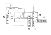
図36には上記した金属板の曲げ加工方法に使用する本発明の金属板の曲げ加工装置の一例が示してある。図36に示す金属板の曲げ加工装置は、電源1の一端に電極3が接続してあり、電源1の他端に曲げ対象である金属板2が接続してあり、電源1と曲げ対象の金属板2に放電を発生させ、金属板2の折り曲げ部に所望の熱歪みを発生させて金属板2を曲げ加工するようになっている。本発明の装置には更に、図36に示すように電極移動手段10、曲げ角度計測手段16、雰囲気制御手段17、検出手段18、制御手段19が設けてある。ここで、上記電極移動手段10は電極3を金属板2に対して移動させるためのもので、電極移動手段10により電極3を金属板2に対して移動する過程で放電を発生させるようになっている。曲げ角度計測手段16は前述の変位センサなどを用いて上記放電を発生させて金属板2を曲げ加工した際の曲げ角度を計測するためのものである。また、本装置においては上記のように雰囲気制御手段17を設けて金属板2と電極3からなる加工部を外部の雰囲気から密封して内部を不活性ガス等の雰囲気にするようになっており、これにより金属板2の酸化の影響を防止するようになっている。また、検出手段18は放電電流や金属板2の曲げ加工部の放電による表面温度変化等のデータを検出するようになっており、この検出手段18により検出したデータに基づいて一回毎の放電による曲げ加工状態及び表面状態が良好に安定するように制御手段19により電源1の電圧、電流や電極移動速度などを制御し、また、金属板2の曲げ加工部が目的とする曲げ角度となるように、必要な放電回数や電極をスキャンするときの放電位置の間隔などを演算して求め、制御手段19によりこれらを制御するようになっている。つまり、検出手段18と制御手段19及び曲げ角度計測手段16と制御手段19とでフィードバック制御手段を構成している。また、制御手段19は制御量の演算等も行っている。上記のような図36に示す本発明の装置を使用することで、電極3を金属板2に対して移動させながら放電を発生させて金属板2を曲げ加工できるものであり、しかも、検出手段18により検出した放電電流や表面温度変化、また曲げ角度計測手段16により計測した曲げ角度等のデータに基づいて制御手段19によりフィードバック制御をして目的とする曲げ角度に加工できるものである。ここで、1回ごとの放電による加工状態が安定している場合は、検出手段18により検出したデータに基づくフィードバック制御は用いなくてもよい。なお、本実施形態においては雰囲気制御手段17を設けた例を示したが、雰囲気制御手段17を設けない場合もある。
【0084】
図37には上記した金属板の曲げ加工方法に使用する本発明の金属板の曲げ加工装置の他例が示してある。図37に示す金属板の曲げ加工装置は、電源1の一端に電極3が接続してあり、電源1の他端に曲げ対象である金属板2が接続してあり、電源1と曲げ対象の金属板2に放電を発生させ、金属板2の折り曲げ部に所望の熱歪みを発生させて金属板2を曲げ加工するようになっている。本発明の装置には更に、図37に示すように電極移動手段10、計測手段20、雰囲気制御手段17、制御手段19が設けてある。ここで、上記電極移動手段10は電極3を金属板2に対して移動させるためのもので、電極移動手段10により電極3を金属板2に対して移動する過程で放電を発生させるようになっている。また、本装置においては上記のように雰囲気制御手段17を設けて金属板2と電極3からなる加工部を外部の雰囲気から密封して内部を不活性ガス等の雰囲気にするようになっており、これにより金属板2の酸化の影響を防止するようになっている。また、計測手段20は金属板2の曲げ加工後における曲げ加工部の結果を特性として計測するためのものである。ここで、曲げ加工部の結果の特性とは、例えばリレーの感動開放電圧特性をアクチュエータバネの曲げ加工で調整するような場合は、接点圧に対応する所定位置の圧力などの力学的特性あるいは感動電圧、開放電圧などの電気的特性に相当する。金属板2の曲げ加工後における曲げ加工部の結果を特性として計測するための計測手段20の一例としては例えば図16に示すようなばね圧を計測する手段9を挙げることができる。そして、この計測手段20により計測した曲げ加工部のデータに基づいて曲げ加工部の特性が目的とする特性となるように金属板2を曲げ加工するように制御手段19により電源1の電圧、電流や電極移動速度あるいは放電回数や電極をスキャンするときの放電位置間隔などを制御するようになっている。このような装置を用いることで、電極3を金属板2に対して移動させながら放電を発生させて金属板2を曲げ加工できるものである。そして、計測手段20により検出した曲げ加工部のデータに基づいて制御手段19によりフィードバック制御をして曲げ加工部が目的とする特性となるように曲げ加工できるものである。なお、本実施形態においては雰囲気制御手段17を設けた例を示したが、雰囲気制御手段17を設けない場合もある。
【0085】
図38には上記図36や図37の装置を含む全体の構成図が示してある。図38において符号50は図11で説明した電源1、コンデンサ6、第1のスイッチ26、第2のスイッチ27を備えた電源コントローラであり、符号51は図26(c)に示す電極3に対して金属板2を任意の位置(X方向、Y方向、Z方向)に移動させるためのNCコントローラのような移動装置である。図38に示す他の符号のものは既に説明しているので説明は省略する。
【0086】
【発明の効果】
上記のように本発明の請求項1記載の発明にあっては、電源と曲げ対象の金属板に放電を発生させる電極からなる装置により金属板の折り曲げ部に所望の熱歪みを発生させて金属板を曲げ加工するに当たり、電極を金属板に接近させ、電極と金属板との間隔を変化させる過程で放電を発生させるので、金属板の材質や厚み等が異なっても電極を移動させる過程で該当する金属板と電極との最適の距離になると最適な放電を確実に発生させることができ、このように電極を移動させて電極と金属板との間隔を変化させるという簡単な方法で金属板の目的とする曲げ加工ができ、また、電極を移動させる過程で該当する金属板と電極との間で確実に放電を発生させて金属板の曲げ加工ができるので、厚板、薄板等種々の金属板の曲げ加工が簡単に行え、特に微小な曲げ加工も可能となるものである。
【0087】
また、請求項2記載の発明にあっては、上記請求項1記載の発明の効果に加えて、接近させた電極を金属板に接触させ、次に電極を金属板よりかい離することにより放電を発生させるので、電極の短い移動距離で確実に放電を発生させて目的とする曲げ加工ができるものであり、また、電極の金属板方向の断面を小さくして局所的に放電をさせて微小な加工ができるものである。
【0088】
また、請求項3記載の発明にあっては、上記請求項1記載の発明の効果に加えて、接近させた電極を金属板に近づける過程で放電を発生させるので、電極を金属板からかい離する過程で放電を発生させる場合に比べて、電極を金属板に近づける過程で放電を発生させると電極と金属板との間隔の距離が長いところで放電が発生し、これにより金属板への熱影響を抑えることができるものである。
【0089】
また、請求項4記載の発明にあっては、上記請求項1記載の発明の効果に加えて、電極と金属板との間隔を変化させる過程で放電を発生させることを複数回繰り返すので、放電を確実に繰り返し発生させて目的とする曲げ加工ができるものである。
【0090】
また、請求項5記載の発明にあっては、上記請求項4記載の発明の効果に加えて、電極に電磁石を取付け、電磁石により電極を移動させて電極と金属板との間隔を変化させる過程で放電を発生させて金属板の折り曲げ部に所望の熱歪みを発生させて金属板を曲げ加工するので、電磁石により電極の移動を制御でき、電磁石という簡便な手段で電極の移動を制御できるものである。
【0091】
また、請求項6記載の発明にあっては、上記請求項4又は請求項5記載の発明の効果に加えて、電極に磁石を有するシャフトを設け、シャフトを電磁石に対向させ、シャフトの電磁石に対向する部分に+又は−の極性を持たせ、電磁石に交流電圧を印加させてシャフトを吸引したり反発させたりすることで電極と金属板との間隔を変化させる動作を繰り返し行い、電極と金属板との間隔を変化させる過程で放電を発生させて金属板の折り曲げ部に所望の熱歪みを発生させることを繰り返して金属板を曲げ加工するので、電磁石に交流電圧を印加させるという簡便な手段で電極の金属板に接近する方向の移動及び金属板からかい離する方向の移動の繰り返しが行えるものである。
【0092】
また、請求項7記載の発明にあっては、上記請求項4又は請求項6記載の発明の効果に加えて、電極に電磁石を取付け、電磁石により電極を移動させて電極と金属板との間隔を変化させる過程で放電を発生させて金属板の折り曲げ部に所望の熱歪みを発生させて金属板を曲げ加工するに当たり、電極の電磁石に印加する電圧の周波数を変えることで、対象部位ごとに電極のかい離回数を制御して金属板の折り曲げ部の対象部位ごとに所望の熱歪みを発生させることを繰り返して金属板を曲げ加工するので、電極の金属板に接近する方向の移動及び金属板からかい離する方向の移動の繰り返しの周期を変えることができて、対象部位毎に最適の曲げ加工ができ、また、電極の電磁石に印加する電圧の周波数を変えるものであるから高速で電極を制御できるものである。
【0093】
また、請求項8記載の発明にあっては、上記請求項4記載の発明の効果に加えて、電極に圧電アクチュエータを設けて電極を移動させて電極と金属板との間隔を変化させる過程で放電を発生させて金属板の折り曲げ部に所望の熱歪みを発生させて金属板を曲げ加工するので、電極の金属板に接近する方向の移動及び金属板からかい離する方向の移動を圧電アクチュエータを用いて実現できて、圧電アクチュエータにより電極の移動を高精度に制御できるものである。
【0094】
また、請求項9記載の発明にあっては、上記請求項1乃至請求項4のいずれかに記載の発明の効果に加えて、電極を移動させて電極と金属板との間隔を変化させる過程で放電を発生させて金属板の折り曲げ部に所望の熱歪みを発生させて金属板を曲げ加工するに当たって、電極と金属板との間隔を変化させる際の電極の移動速度を制御することで金属板の曲げ角度を制御するので、電極の移動速度を制御するという簡単な方法で金属板の曲げ角度を目的とする曲げ角度に制御することができるものである。
【0095】
また、請求項10記載の発明にあっては、上記請求項1乃至請求項4のいずれかに記載の発明の効果に加えて、電源の電圧を制御することにより、金属板の曲げ角度を制御するので、電源の電圧を変えるという簡単な方法で金属板の曲げ角度を目的とする曲げ角度に制御することができるものである。
【0096】
また、請求項11記載の発明にあっては、上記請求項1乃至請求項4のいずれかに記載の発明の効果に加えて、電源からの電荷を充電するためのコンデンサと、コンデンサに充電した電荷を電極と金属板との間に放電させるための手段とを備え、電極を移動させて電極と金属板との間隔を変化させる過程でコンデンサに充電した電荷を瞬間的に放電させて金属板の折り曲げ部に所望の熱歪みを発生させて金属板を曲げ加工するので、コンデンサに充電した電荷を放電するという簡単な方法で瞬間的に大電流を放電できて確実に放電を発生させて金属板を曲げ加工することができて、電源の効率化が図れるものである。
【0097】
また、請求項12記載の発明にあっては、上記請求項1又は請求項2又は請求項4記載の発明の効果に加えて、電源と電極との間又は電源と金属板との間にコイルを設け、電極を移動させて電極と金属板との間隔を変化させるときにコイルが発生する誘導起電力を利用して放電を発生させて金属板の折り曲げ部に所望の熱歪みを発生させて金属板を曲げ加工するので、電極をかい離するときにコイルが発生する誘導起電力を利用して簡単且つ確実に放電を発生させることができるものである。
【0098】
また、請求項13記載の発明にあっては、上記請求項1乃至請求項4のいずれかに記載の発明の効果に加えて、金属板の曲げ加工計測手段により金属板の曲げ状態を計測するので、金属板の加工、曲げ状態の計測を繰り返して簡単に目的とする曲げ加工ができるものである。
【0099】
また、請求項14記載の発明にあっては、上記請求項13記載の発明の効果に加えて、放電により折り曲げられた金属板の折り曲げ線から電極を折り曲げ線と直交する水平方向に任意の距離移動してその水平方向の距離を求めると共に、該水平方向に移動した位置で電極を下降させて曲げられた金属板に当接させて金属板の折り曲げ線から電極までの垂直方向の距離を求め、上記水平方向の距離と垂直方向の距離から金属板の曲げ角度を計測するので、金属板の曲げ加工に使用する電極を利用して金属板の曲げ角度を計測することができ、金属板の曲げ角度の計測が簡単にできるものである。
【0100】
また、請求項15記載の発明にあっては、上記請求項13に記載の発明の効果に加えて、放電により折り曲げられた金属板の曲げ角度を放電に用いた2個の電極により求めるものであって、2個の電極を金属板の折り曲げ線と直交する水平方向に任意の距離移動して移動後における2個の電極間の金属板の折り曲げ方向と直交する水平方向の距離を求めると共に、該水平方向に移動した位置で2個の電極を下降させて曲げられた金属板に当接させて2個の電極間の垂直方向の距離を求め、上記水平方向の距離と垂直方向の距離から金属板の曲げ角度を計測するので、金属板の曲げ加工に使用する電極を利用して金属板の曲げ角度を計測することができ、金属板の曲げ角度の計測が簡単にできるものである。
【0101】
また、請求項16記載の発明にあっては、上記請求項13記載の発明の効果に加えて、放電により折り曲げられた金属板の曲げ部にばね圧を計測する手段を接触させて、接触圧により曲げ状態を計測するので、放電により折り曲げられた金属板の曲げ部のばね圧を計測でき、これにより曲げ加工に当たって金属板の曲げ部が目的とするばね圧を有するようにフィードバック制御することができるものである。
【0102】
また、請求項17記載の発明にあっては、上記請求項1乃至請求項4、請求項9乃至請求項12のいずれかに記載の発明の効果に加えて、放電により金属板を折り曲げるに当たって金属板の曲げ加工を制御する制御手段を設け、金属板の複数のねらいの角度に対する制御手段の制御量の関係のデータを収集して、その関係から制御量と曲げ角度との関係式を算出し、このようにして算出した制御量と曲げ角度との関係式に基づいて目的とする曲げ角度となるように制御量を制御するので、金属板を放電で曲げ加工するに当たっての初期調整の精度を向上することができ、初期調整後における金属板の曲げ加工が正確にできるものである。
【0103】
また、請求項18記載の発明にあっては、上記請求項17記載の発明の効果に加えて、金属板の複数のねらいの角度に対する制御手段の制御量の関係のデータを収集して、その関係から制御量と曲げ角度との関係式を算出し、同様にして更に制御量と曲げ角度との関係式を複数求め、上記のようにして複数の異なる関係式を求めた後に、1回目の曲げ加工を行って曲げ角度と制御量とを求めて上記複数種類の関係式のうち最も近い関係式を選択し、2回目以降の曲げ加工において選択した関係式に基づいて制御量を決定するので、金属板のばらつきに応じて最適の制御量と曲げ角度との関係式を選択して制御することができるものである。
【0104】
また、請求項19記載の発明にあっては、上記請求項17記載の発明の効果に加えて、金属板の複数のねらいの角度に対する制御手段の制御量の関係のデータを収集して、その関係から制御量と曲げ角度との関係式を算出し、同様にして更に制御量と曲げ角度との関係式を複数求め、上記のようにして複数の異なる関係式を求めた後に、金属板の1次曲げ加工を行って曲げ角度と制御量とを求めて上記複数種類の関係式のうち最も近い関係式を選択し、目的とする曲げ角度と上記1次曲げ加工による曲げ角度との差を求め、上記選択された関係式に基づき上記角度の差に対応する制御量を算出し、このようにして算出した制御量となるように制御して2次曲げ加工をして曲げ角度の調整を行うので、目的とする角度への調整が容易に行えるものである。
【0105】
また、請求項20記載の発明にあっては、上記請求項17記載の発明の効果に加えて、金属板の複数のねらいの角度に対する制御手段の制御量の関係のデータを収集して、その関係から制御量と曲げ角度との関係式を算出し、このようにして算出した制御量と曲げ角度との関係式に基づいて目的とする曲げ角度となるように制御量を制御し、上記制御量により1〜Nの金属板の曲げ加工を行い、1〜Nの金属板の曲げ角度と制御量との関係のデータをもとに制御量と曲げ角度との次の関係式を算出し、このようにして算出した制御量と曲げ角度との次の関係式に基づいて目的とする曲げ角度となるように制御量を制御するので、ロット変動や電極の消耗などの外乱の変化に応じて調整データの最適化が図れ、ロット変動や電極の消耗などの外乱の変化があっても正確に金属板の曲げ加工ができるものである。
【0106】
また、請求項21記載の発明にあっては、上記請求項1乃至請求項4のいずれかに記載の発明の効果に加えて、金属板の曲げ加工を内部を不活性ガス雰囲気としたチャンバー内において行うので、外部の雰囲気の影響を受けず金属板の酸化の影響を抑えることができるものである。
【0107】
また、請求項22記載の発明にあっては、上記請求項1乃至請求項4のいずれかに記載の発明の効果に加えて、放電の状態や金属板の曲げ加工の状態を計測し、計測データに基づいて金属板の曲げ加工をフィードバック制御手段により制御するので、安定した曲げ加工ができるものである。
【0108】
また、請求項23記載の発明にあっては、上記請求項22記載の発明の効果に加えて、曲げ角度を制御するための放電電流検知手段を設けて放電電流を計測し、この放電電流の計測データに基づいて金属板の曲げ加工をフィードバック制御手段により制御するので、放電電流の計測データに基づいて金属板の目的とする曲げ角度となるような最適の放電電流となるように制御できて、安定した曲げ加工ができるものである。
【0109】
また、請求項24記載の発明にあっては、上記請求項22記載の発明の効果に加えて、金属板の表面温度を計測し、この金属板の表面温度の計測データに基づいて金属板の曲げ加工をフィードバック制御手段により制御するので、金属板の表面温度の計測データに基づいて金属板の目的とする曲げ角度となるような最適の表面温度となるように放電電圧を制御できて、安定した曲げ加工ができるものである。
【0110】
また、請求項25記載の発明にあっては、上記請求項1乃至請求項4のいずれかに記載の発明の効果に加えて、電極を電極位置制御装置により位置制御するので、電極位置制御装置により電極を金属板に対して移動することができるものである。
【0111】
また、請求項26記載の発明にあっては、上記請求項25記載の発明の効果に加えて、複数回曲げ調整を行うに当たり、毎回電極の位置を微小に移動させるので、複数回曲げ調整を行う場合、毎回微小に電極の位置を移動させて放電して金属板の曲げ加工をすることで金属板の表面の熱影響を抑えることができるものである。
【0112】
また、請求項27記載の発明にあっては、上記請求項25記載の発明の効果に加えて、金属板の曲げ加工において曲げ角度が同じで変位量が異なるものに対して、電極の位置を横方向に変化させることで同じ曲げ角度で異なる変位量の曲げ加工を行うので、金属板の曲げ加工において同じ曲げ角度でも電極の位置を変化させるだけで簡単に変位量を制御できるものである。
【0113】
また、請求項28記載の発明にあっては、上記請求項1乃至請求項4のいずれかに記載の発明の効果に加えて、金属板の折り曲げ線上に電極を複数並べるので、電極を折り曲げ線に沿って移動させることなく、又は移動量を少なくして一度に又は少ない移動量で容易に金属板の曲げ加工ができるものである。
【0114】
また、請求項29記載の発明にあっては、上記請求項28記載の発明の効果に加えて、金属板の折り曲げ線上に複数並べた電極と並行して変位センサを配置して金属板のねじれ状態を監視するので、折り曲げ線上に複数並べた電極により金属板を折り曲げる際折り曲げ線に沿った各部における曲げ角度が不均一になってねじれ状態が発生しても、このねじれを変位センサにより検出して均一な曲げ角度となるように制御することができるものである。
【0115】
また、請求項30記載の発明にあっては、上記請求項1乃至請求項4、請求項28記載のいずれかに記載の発明の効果に加えて、電極を金属板の2箇所以上に配置して複数の電極の動作のタイミングをずらすので、複数の電極の動作をずらして金属板を複雑な形状に加工することができるものである。
【0116】
また、請求項31記載の発明にあっては、上記請求項1乃至請求項4、請求項28記載のいずれかに記載の発明の効果に加えて、電極を金属板の表面側と裏面側とにそれぞれ配置して表裏いずれかの電極と金属板との間に放電を発生させるかを選択して金属板を曲げ加工するので、金属板を表側又は裏側に容易に曲げ加工できるものであり、また、曲げ角度の曲げすぎなどに対しては反対方向の電極を用いて放電を発生させて曲げ角度を反対側から容易に調整することができるものである。
【0117】
また、請求項32記載の発明にあっては、上記請求項1乃至請求項4、請求項27,請求項28記載のいずれかに記載の発明の効果に加えて、金属板の折り曲げ線上に電極を複数回打点を繰り返しながらスキャンさせるので、幅を持った金属板の曲げ加工が1つの電極のスキャンにより容易にできるものである。
【0118】
また、請求項33記載の発明にあっては、上記請求項32に記載の発明の効果に加えて、金属板の折り曲げ線上に電極を複数回スキャンさせるに当たって、始めは曲げ量が大きくなるように制御し、スキャン回数が増すにつれ曲げ角度が小さくなるように制御するので、精密な曲げ加工ができるものである。
【0119】
また、請求項34記載の発明にあっては、上記請求項32記載の発明の効果に加えて、金属板の折り曲げ線に並行して設けた測定ラインの上に複数の変位センサを配置して、曲げによる測定ライン位置の変位を測定し、金属板の両側の曲げ角度が均一になるように、電極スキャン位置に対応して曲げ加工条件を制御するので、電極をスキャンしながら金属板の曲げ加工を行う際に、電極のかい離の回数や放電の電圧を制御することにより、始点と終点の曲げ角度を均一にしてねじれを無くすことができ、この結果、ねじれの無い曲げ加工が容易にできるものである。
【0120】
また、請求項35記載の発明にあっては、電源と曲げ対象の金属板に放電を発生させる電極とを備えて金属板の折り曲げ部に所望の熱歪みを発生させて金属板を曲げ加工する金属板の曲げ加工装置であって、該装置に電極と金属板との間隔を変化させる過程で放電を発生させるように電極を金属板に対して移動させるための電極移動手段と、金属板の曲げ加工後の曲げ角度を計測する金属板の曲げ角度計測手段と、曲げ角度計測手段により計測した曲げ角度と目的とする曲げ角度との差に基づいて、金属板の曲げ加工部が目的とする曲げ角度となるように曲げ加工条件を制御するための制御手段とを設けてあるので、電極を金属板に対して移動させながら放電を発生させて金属板を曲げ加工でき、しかも、曲げ角度計測手段により計測した曲げ角度と目的とする曲げ角度との差に基づいて制御手段によりフィードバック制御をして目的とする曲げ角度に加工できるものである。
【0121】
また、請求項36記載の発明にあっては、電源と曲げ対象の金属板に放電を発生させる電極とを備えて金属板の折り曲げ部に所望の熱歪みを発生させて金属板を曲げ加工する金属板の曲げ加工装置であって、該装置に、該装置に電極と金属板との間隔を変化させる過程で放電を発生させるように電極を金属板に対して移動させるための電極移動手段と、金属板の曲げ加工後における曲げ加工部の結果を特性として計測する計測手段と、計測手段により計測した曲げ加工部のデータに基づいて曲げ加工部の特性が目的とする特性となるように金属板を曲げ加工するように曲げ加工条件を制御するための制御手段とを設けるので、電極を金属板に対して移動させながら放電を発生させて金属板を曲げ加工でき、しかも、計測手段により検出した曲げ加工部のデータに基づいて制御手段によりフィードバック制御をして曲げ加工部が目的とする特性となるように曲げ加工できるものである。
【図面の簡単な説明】
【図1】本発明の概略構成図である。
【図2】(a)乃至(c)は同上の放電による金属板の曲げ加工の原理を示す説明図である。
【図3】同上の電極を金属板からかい離して放電をする例の概略構成図である。
【図4】(a)は同上の電極を金属板の方に移動しながら放電をする例の概略構成図であり、(b)は電極を金属板の方に移動しながら放電をする場合の放電の発生する距離を示す説明図であり、(c)は電極を金属板からかい離して放電をする場合の放電の発生する距離を示す説明図である。
【図5】同上の電極移動移動手段を設けた実施形態の概略構成図である。
【図6】(a)(b)は電極移動手段の一例の動作説明図である。
【図7】同上の電極移動手段の他例の説明図である。
【図8】同上の電極移動手段の更に他例の説明図である。
【図9】同上の電極移動速度制御手段を設けた実施形態の概略構成図である。
【図10】同上の電圧変更手段を設けた実施形態の概略構成図である。
【図11】(a)は同上のコンデンサに充電した電荷を放電する例の回路図であり、(b)は同上の第2のスイッチのオン、電極の上昇移動又は下降移動、放電発生のタイミングを示すタイムチャートである。
【図12】同上のコイルに発生する誘導起電力を利用して放電する例の回路図である。
【図13】(a)は同上の曲げ角度計測手段を設けた例を示す概略構成図であり、(b)は同上のフローチャートである。
【図14】同上の曲げ角度計測手段の一例を示す概略構成図である。
【図15】同上の曲げ角度計測手段の他例を示す概略構成図である。
【図16】同上のばね圧を計測する手段を設けた例を示す概略構成図である。
【図17】(a)(b)は同上の制御量と曲げ角度の関係を示すグラフである。
【図18】同上の複数の補正曲線を示すグラフである。
【図19】同上の補正曲線の曲げ角度と制御量との関係を示すグラフである。
【図20】同上の全体のフローチャートである。
【図21】同上の補正曲線の更新を説明するグラフである。
【図22】同上の不活性雰囲気で加工する例を示す概略構成図である。
【図23】同上のフィードバック制御手段によりフィードバック制御する例を示す概略構成図である。
【図24】同上の放電電流検知によりフィードバック制御する例の概略構成図である。
【図25】同上の温度センサの温度検知によりフィードバック制御する例の概略構成図である。
【図26】(a)は同上の電極位置制御装置により電極位置を制御する例の概略構成図であり、(b)は同上の電極の移動の説明図であり、(c)は同上の金属板の移動の説明図である。
【図27】同上の曲げ加工位置を微小に変化させる例を示す説明図である。
【図28】(a)(b)は同上の同じ曲げ角度で変位量を制御する例を示す説明図である。
【図29】(a)(b)は同上の折り曲げ線上に複数個の電極を配置して曲げ加工を行う例を示す説明図である。
【図30】(a)(b)は同上の複数の変位センサを配置して曲げ加工を行う例を示す説明図である。
【図31】(a)(b)(c)は同上の複数の電極を用いて複雑な形状の曲げ加工を行う例を示す説明図である。
【図32】(a)(b)(c)は同上の金属板の両側に電極を配置して曲げ加工を行う例を示す説明図である。
【図33】同上の折り曲げ線上に沿って電極をスキャンする例を示す説明図である。
【図34】(a)(b)は回数が増すに連れて曲げ角度が小さくなるように制御する例を示す説明図であり、(c)は回数が増すに連れて曲げ角度が小さくなるように制御する例を示すグラフである。
【図35】同上の折り曲げ線上に複数の変位センサを配置して曲げ加工を行う例を示す説明図である。
【図36】本発明の装置を示す概略構成図である。
【図37】同上の他の実施形態の装置を示す概略構成図である。
【図38】本発明の装置全体を示す概略構成図である。
【符号の説明】
1 電源
2 金属板
3 電極
4 電磁石
5 圧電アクチュエータ
6 コンデンサ
7 コイル
8 曲げ角度計測手段
9 ばね圧を計測する手段
11 チャンバー
12 フィードバック制御手段
13 電極位置制御装置
14 変位センサ
16 曲げ角度計測手段
17 雰囲気制御手段
18 検出手段
19 制御手段
20 計測手段[0001]
BACKGROUND OF THE INVENTION
The present invention relates to a metal plate bending method and apparatus for heating and bending a metal plate.
[0002]
[Prior art]
Conventionally, a method of bending a metal plate by heating is known from Japanese Patent Application Laid-Open Nos. 55-130339 and 62-93028.
[0003]
In the conventional example disclosed in Japanese Patent Laid-Open No. 55-130339, a reverse plasma is generated in a bent portion of a metal plate, and a desired thermal strain is generated in the bent portion of the metal plate to process the metal plate. . In this conventional example, the plasma arc is generated in a state where the electrode is separated from the metal plate by a predetermined distance. Therefore, the material or thickness of the metal plate is changed, or the current value is changed. If there is a change, etc., it will be necessary to readjust the position of the electrode each time in order to generate a plasma arc, and the adjustment of the position of the electrode will be extremely troublesome. Therefore, bending of large metal plates will be supported. Although it was possible, there was a problem that it was not suitable for micro bending.
[0004]
In the conventional example disclosed in Japanese Patent Laid-Open No. 62-93028, a metal plate is irradiated with a laser beam to generate a desired thermal strain in a bent portion of the metal plate to process the metal plate. . In this conventional example, it is necessary to change the wavelength of the laser according to the material conditions such as the material and thickness of the metal plate, and there is a problem that control under the same conditions is difficult.
[0005]
[Problems to be solved by the invention]
The present invention has been made in view of the above points, and it is possible to bend a metal plate by reliably discharging with a simple method and apparatus, and it can be easily performed even with a minute bending process. An object of the present invention is to provide a metal plate bending method and apparatus that can be used.
[0006]
[Means for Solving the Problems]
In order to solve the above-mentioned problems, a method for bending a metal plate according to the present invention includes a power source 1 and an electrode 3 that generates an electric discharge in the metal plate 2 to be bent. When the metal plate 2 is bent by generating the electrode, the electrode 3 is brought close to the metal plate 2 and discharge is generated in the process of changing the distance between the electrode 3 and the metal plate 2. By adopting such a method, an electric discharge is generated in the process of moving the electrode 3 and changing the distance between the electrode 3 and the metal plate 2 to generate a desired thermal strain in the bent portion of the metal plate 2. The metal plate 2 can be bent, and even if the material, thickness, etc. of the metal plate 2 are different, the discharge can be reliably generated in the process of moving the electrode 3 and the intended bending can be performed.
[0007]
Moreover, it is preferable to generate an electric discharge by bringing the electrode 3 approached into contact with the metal plate 2 and then separating the electrode 3 from the metal plate 2. By adopting such a method, a desired bending process can be performed by reliably generating a discharge over a short moving distance.
[0008]
Further, it is preferable to generate a discharge in the process of bringing the approached electrode 3 closer to the metal plate 2. By adopting such a method, when the discharge is generated in the process of bringing the electrode 3 closer to the metal plate 2 as compared with the case where the discharge is generated in the process of separating the electrode 3 from the metal plate 2, the electrode 3 and the metal plate Discharge occurs where the distance between the metal plate 2 and the metal plate 2 is long, so that the heat effect on the metal plate 2 can be suppressed.
[0009]
Further, it is preferable to repeat the generation of the discharge a plurality of times in the process of changing the distance between the electrode 3 and the metal plate 2. By adopting such a method, it is possible to reliably generate electric discharge repeatedly and to perform a desired bending process.
[0010]
Also, an electromagnet 4 is attached to the electrode 3, and the electrode 3 is moved by the electromagnet 4. Then, a discharge is generated in the process of changing the distance between the electrode 3 and the metal plate 2 to generate a desired thermal strain in the bent portion of the metal plate 2 to bend the metal plate 2. It is preferable. By adopting such a method, the movement of the electrode 3 can be controlled by the electromagnet 4.
[0011]
Also, A shaft 21 having a magnet is provided on the electrode 3, the shaft 21 is opposed to the electromagnet 4, a portion of the shaft 21 facing the electromagnet 4 is given a positive or negative polarity, and an AC voltage 35 is applied to the electromagnet 4 to form a shaft. The operation of changing the distance between the electrode 3 and the metal plate 2 is repeated by sucking or repelling 21, and a discharge is generated in the process of changing the distance between the electrode 3 and the metal plate 2 to thereby generate the metal plate 2. The metal plate 2 is bent by repeatedly generating a desired thermal strain in the bent portion of the metal plate 2 It is preferable. By adopting such a method, an AC voltage is applied to the electromagnet 4 so that the movement of the electrode 3 in the direction approaching the metal plate 2 and the movement in the direction away from the metal plate 2 can be repeated.
[0012]
Also, An electromagnet 4 is attached to the electrode 3, and the electrode 3 is moved by the electromagnet 4 to generate a discharge in the process of changing the distance between the electrode 3 and the metal plate 2, thereby generating a desired thermal strain in the bent portion of the metal plate 2. When bending the metal plate 2, the frequency of the voltage applied to the electromagnet 4 of the electrode 3 is changed to control the number of separations of the electrode 3 for each target portion, and for each target portion of the bent portion of the metal plate 2. Bending the metal plate 2 by repeatedly generating a desired thermal strain It is preferable. By adopting such a method, the repetition cycle of the movement of the electrode 3 in the direction approaching the metal plate 2 and the movement in the direction of moving away from the metal plate 2 can be changed, and the optimum processing for each target part. Can do.
[0013]
Moreover, the electrode 3 is moved by providing the electrode 3 with the piezoelectric actuator 5. Then, a discharge is generated in the process of changing the distance between the electrode 3 and the metal plate 2 to generate a desired thermal strain in the bent portion of the metal plate 2 to bend the metal plate 2. It is preferable. By adopting such a method, the movement of the electrode 3 in the direction approaching the metal plate 2 and the movement in the direction away from the metal plate 2 can be realized by using the piezoelectric actuator 5.
[0014]
Also, In the process of bending the metal plate 2 by generating a desired thermal strain in the bent portion of the metal plate 2 by generating a discharge in the process of moving the electrode 3 and changing the distance between the electrode 3 and the metal plate 2, When changing the distance between 3 and the metal plate 2 The bending angle of the metal plate 2 can be controlled by a simple method of controlling the moving speed of the electrode 3.
[0015]
Moreover, it is preferable to control the bending angle of the metal plate 2 by controlling the voltage of the power source 1. By adopting such a method, the bending angle of the metal plate 2 can be controlled by a simple method of changing the voltage of the power source 1.
[0016]
Further, a capacitor 6 for charging the electric charge from the power source 1 and means for discharging the electric charge charged in the capacitor 6 between the electrode 3 and the metal plate 2 are provided. In the process of moving the electrode 3 and changing the distance between the electrode 3 and the metal plate 2, the electric charge charged in the capacitor 6 is instantaneously discharged to generate a desired thermal strain in the bent portion of the metal plate 2 and thereby the metal. Bending plate 2 It is preferable. By adopting such a method, a large current can be instantaneously discharged and a discharge can be reliably generated.
[0017]
Further, a coil 7 is provided between the power source 1 and the electrode 3 or between the power source 1 and the metal plate 2. When the electrode 3 is moved to change the distance between the electrode 3 and the metal plate 2, a discharge is generated using the induced electromotive force generated by the coil 7, and a desired thermal strain is applied to the bent portion of the metal plate 2. Generate and bend the metal plate 2 This is true. By adopting such a method, discharge can be generated using the induced electromotive force generated by the coil 7 when the electrode 3 is separated.
[0018]
Moreover, it is preferable to measure the bending state of the metal plate 2 by means of a bending process measuring unit for the metal plate 2. By adopting such a method, the intended bending process can be performed by repeatedly processing the metal plate 2 and measuring the bending state.
[0019]
Further, the electrode 3 is moved by an arbitrary distance in the horizontal direction perpendicular to the bending line from the bending line of the metal plate 2 bent by the discharge to obtain the horizontal distance, and the electrode 3 is moved at the position moved in the horizontal direction. The metal plate 2 is brought into contact with the bent metal plate 2 to obtain a vertical distance from the folding line of the metal plate 2 to the electrode 3, and the bending angle of the metal plate 2 is determined from the horizontal distance and the vertical distance. Is preferably measured. By adopting such a method, the bending angle of the metal plate 2 can be easily measured using the electrode 3 used for bending the metal plate 2.
[0020]
Further, the bending angle of the metal plate 2 bent by the discharge is obtained by the two electrodes 3 used for the discharge, and the two electrodes 3 are arbitrarily set in the horizontal direction perpendicular to the bending line of the metal plate 2. The distance in the horizontal direction perpendicular to the bending direction of the metal plate 2 between the two electrodes 3 after the movement is obtained, and the two electrodes 3 are lowered and bent at the position moved in the horizontal direction. It is preferable that the vertical distance between the two electrodes 3 is obtained by contacting the metal plate 2 and the bending angle of the metal plate 2 is measured from the horizontal distance and the vertical distance. By adopting such a method, the bending angle of the metal plate 2 can be easily measured using the electrode 3 used for bending the metal plate 2.
[0021]
Moreover, it is preferable to measure the bending state by the contact pressure by bringing the means 9 for measuring the spring pressure into contact with the bent portion of the metal plate 2 bent by the discharge. By adopting such a method, the spring pressure of the bent portion of the metal plate 2 bent by electric discharge can be measured, and thus feedback control is performed so that the bent portion of the metal plate 2 has a desired spring pressure during processing. Is something that can be done.
[0022]
Further, a control means for controlling the bending process of the metal plate 2 when the metal plate 2 is bent by electric discharge is provided, and data on the relationship of the control amount of the control means with respect to a plurality of target angles of the metal plate 2 is collected, and the relationship It is preferable that a relational expression between the control amount and the bending angle is calculated from the control amount, and the control amount is controlled so as to obtain a target bending angle based on the relational expression between the control amount and the bending angle thus calculated. By adopting such a method, it is possible to improve the accuracy of the initial adjustment in bending the metal plate 2 by electric discharge.
[0023]
Further, data on the relationship of the control amount of the control means with respect to a plurality of target angles of the metal plate 2 is collected, and a relational expression between the control amount and the bending angle is calculated from the relationship, and similarly, the control amount and the bending amount are further calculated. After obtaining a plurality of relational expressions with the angle and obtaining a plurality of different relational expressions as described above, the first bending process is performed to obtain the bending angle and the control amount, and the most of the above-mentioned plural kinds of relational expressions. It is preferable to select a close relational expression and determine the control amount based on the relational expression selected in the second and subsequent bending processes. By adopting such a method, the relational expression between the optimal control amount and the bending angle can be selected and controlled according to the variation of the metal plate 2.
[0024]
Further, data on the relationship of the control amount of the control means with respect to a plurality of target angles of the metal plate 2 is collected, and a relational expression between the control amount and the bending angle is calculated from the relationship, and similarly, the control amount and the bending amount are further calculated. After obtaining a plurality of relational expressions with the angle and obtaining a plurality of different relational expressions as described above, the metal plate 2 is subjected to primary bending to obtain the bending angle and the control amount, and the plurality of kinds of relational expressions are obtained. The closest relational expression is selected, the difference between the target bending angle and the bending angle by the primary bending process is obtained, and the control amount corresponding to the difference in angle is calculated based on the selected relational expression. It is preferable to adjust the bending angle by performing the secondary bending process so that the control amount calculated in this way is obtained. By adopting such a method, the adjustment to the target angle can be easily performed.
[0025]
Further, data on the relationship of the control amount of the control means with respect to a plurality of target angles of the metal plate 2 is collected, a relational expression between the control amount and the bending angle is calculated from the relationship, and the control amount thus calculated is calculated. Based on the relational expression between the bending angle and the bending angle, the control amount is controlled so that the target bending angle is obtained, the 1-N metal plate 2 is bent by the control amount, and the 1-N metal plate 2 is bent. Based on the data on the relationship between the bending angle and the controlled variable, the following relational expression between the controlled variable and the bending angle is calculated, and the purpose is based on the following relational expression between the controlled variable and the bending angle calculated in this way. It is preferable to control the control amount so that the bending angle is as follows. By adopting such a method, it is possible to optimize the adjustment data in accordance with disturbance changes such as lot fluctuations and electrode 3 wear in the production of the metal plate.
[0026]
Moreover, it is preferable to perform the bending process of the metal plate 2 in the chamber 11 in which the inside is an inert gas atmosphere. By adopting such a method, the influence of oxidation of the metal plate 2 can be suppressed.
[0027]
Moreover, it is preferable to measure the state of electric discharge and the state of bending of the metal plate 2 and control the bending of the metal plate 2 by the feedback control means 12 based on the measurement data. By adopting such a method, the intended bending process can be realized stably.
[0028]
Moreover, it is preferable to provide a discharge current detecting means for controlling the bending angle, measure the discharge current, and control the bending of the metal plate 2 by the feedback control means 12 based on the measurement data of the discharge current. By adopting such a method, the discharge current is measured by the discharge detection means, and feedback control is performed by the feedback control means 12 based on this discharge current so that a predetermined discharge current is obtained, and the desired bending process is performed. It can be done.
[0029]
Further, it is preferable to measure the surface temperature of the metal plate 2 and control the bending process of the metal plate 2 by the feedback control means 12 based on the measurement data of the surface temperature of the metal plate 2. By adopting such a method, the target bending can be performed by performing feedback control such as controlling the discharge voltage by monitoring the difference between the detected value of the surface temperature of the metal plate 2 and the normal value. .
[0030]
Further, the position of the electrode 3 is preferably controlled by the electrode position control device 13. By adopting such a method, the electrode 3 can be moved with respect to the metal plate 2 by the electrode position control device 13.
[0031]
Further, when performing the bending adjustment a plurality of times, it is preferable to slightly move the position of the electrode 3 each time. By adopting such a method, when the bending adjustment is performed a plurality of times, the position of the electrode 3 is slightly moved each time to discharge and bend the metal plate 2 to effect the thermal effect on the surface of the metal plate 2. Can be suppressed.
[0032]
In addition, it is preferable to perform bending processing with different displacement amounts at the same bending angle by changing the position of the electrode 3 in the lateral direction with respect to the metal plate 2 having the same bending angle and different displacement amounts. . By adopting such a method, the metal plate 2 can be processed into different displacement amounts by changing the position of the electrode 3 even at the same bending angle.
[0033]
Moreover, it is preferable to arrange a plurality of electrodes 3 on the folding line of the metal plate 2. By adopting such a method, the metal plate 2 can be easily bent at a time or with a small amount of movement without moving the electrode 3 along the bend line or with a small amount of movement. is there.
[0034]
In addition, it is preferable to monitor the twisted state of the metal plate 2 by disposing a displacement sensor 14 in parallel with the plurality of electrodes 3 arranged on the folding line of the metal plate 2. By adopting such a method, when the metal plate 2 is bent by a plurality of electrodes 3 arranged on the fold line, if the bending angle at each part along the fold line becomes uneven and a twist state occurs, this twist is reduced. It can be controlled so as to have a uniform bending angle as detected by the displacement sensor 14.
[0035]
In addition, it is preferable to dispose the electrodes 3 at two or more locations on the metal plate 2 to shift the operation timing of the plurality of electrodes 3. Thus, the metal plate 2 can be bent into a complicated shape by shifting the operation timing of the plurality of electrodes 3.
[0036]
Further, the metal plate 2 is bent by selecting whether the electrode 3 is disposed on the front surface side and the back surface side of the metal plate 2 and discharging is generated between the front and back electrodes 3 and the metal plate 2. It is preferable. By adopting such a method, the metal plate 2 can be bent to the front side or the back side, and when the bending angle is excessively bent, the electrode 3 in the opposite direction is used to generate a discharge, and the bending angle is adjusted. It can be adjusted.
[0037]
Further, it is preferable to scan the electrode 3 on the bending line of the metal plate 2 while repeating the hitting point a plurality of times. By adopting such a method, bending of the metal plate 2 having a width can be performed with one electrode 3.
[0038]
Further, when the electrode 3 is scanned a plurality of times on the bend line of the metal plate 2, it is preferable to control the bending amount to be large at first, and to control the bending angle to be decreased as the number of scans is increased. By adopting such a method, precise bending can be performed.
[0039]
Further, a plurality of displacement sensors 14 are arranged on a measurement line provided in parallel with the bending line of the metal plate 2 to measure the displacement of the measurement line position due to bending, and the bending angles on both sides of the metal plate 2 are uniform. It is preferable to control the bending process conditions corresponding to the electrode scan position. By adopting such a method, when bending the metal plate 2 while scanning the electrode 3, the bending angle between the starting point and the ending point is controlled by controlling the number of separations of the electrode 3 and the discharge voltage. It can be made uniform and twist can be eliminated.
[0040]
The metal plate bending apparatus of the present invention includes a power source 1 and an electrode 3 that generates electric discharge in the metal plate 2 to be bent, and generates a desired thermal strain in a bent portion of the metal plate 2 to generate a metal plate. 2 is a bending apparatus for bending a metal plate 2, and the electrode 3 is moved with respect to the metal plate 2 so that the apparatus generates a discharge in the process of changing the distance between the electrode 3 and the metal plate 2. An electrode moving means 10 for making the metal plate 2, a bending angle measuring means 16 for measuring a bending angle of the metal plate 2 after bending, a bending angle measured by the bending angle measuring means 16 and a target bending angle; On the basis of the difference, a control means 19 is provided for controlling the bending conditions so that the bent portion of the metal plate 2 has a desired bending angle. With such a configuration, the metal plate 2 can be bent by generating an electric discharge while moving the electrode 3 relative to the metal plate 2, and the bending angle measured by the bending angle measuring means 16 and the object are set. Based on the difference from the bending angle, the control means 19 can perform feedback control to process the target bending angle.
[0041]
Further, the metal plate 2 is bent by a power source 1 and an electrode 3 that generates a discharge in the metal plate 2 to be bent, and the metal plate 2 is bent by generating a desired thermal strain in the bent portion of the metal plate 2. An apparatus for moving the electrode 3 with respect to the metal plate 2 so as to generate a discharge in the process of changing the distance between the electrode 3 and the metal plate 2; The measuring means 20 that measures the result of the bent portion after the bending process of 2 as a characteristic, and the characteristic of the bent portion based on the data of the bent portion measured by the measuring means 20 so as to be the desired bending characteristic. Control means 19 for controlling bending conditions may be provided. With such a configuration, the metal plate 2 can be bent by generating an electric discharge while moving the electrode 3 relative to the metal plate 2, and based on the data of the bent portion detected by the measuring means 20. The control means 19 can perform feedback control so that the bent portion has the desired characteristics.
[0042]
DETAILED DESCRIPTION OF THE INVENTION
Hereinafter, the present invention will be described based on embodiments shown in the accompanying drawings.
[0043]
FIG. 1 shows a basic schematic configuration diagram of the metal plate bending method of the present invention. In the figure, reference numeral 1 denotes a power source, an electrode 3 is connected to one end of the power source 1, a metal plate 2 to be bent is connected to the other end of the power source 1, and the power source 1 and the metal plate 2 to be bent are connected to each other. The metal plate 2 is bent by generating electric discharge and generating a desired thermal strain at the bent portion of the metal plate 2.
[0044]
Here, in the present invention, the electrode 3 is moved closer to the metal plate 2 and the electrode 3 is moved by the electrode moving means 10 to generate a discharge in the process of changing the distance between the electrode 3 and the metal plate 2. Yes. Since the discharge is generated in the process of changing the distance between the electrode 3 and the metal plate 2 by moving the electrode 3 in this way, the material or thickness of the metal plate 2 to be bent is different or the voltage of the power source 1 is changed. Even if they are different from each other, a discharge is surely generated between the metal plate 2 to be bent and the electrode 3 in the process of moving the electrode 3, and a desired thermal strain is generated in the bent portion of the metal plate 2, thereby It can be bent.
[0045]
Hereinafter, based on FIG. 2, a desired thermal strain is generated in the bent portion of the metal plate 2 by generating an electric discharge in the process of moving the electrode 3 and changing the distance between the electrode 3 and the metal plate 2. The principle of bending 2 will be described. 2A shows a state before discharge, FIG. 2B shows a state during discharge, and FIG. 2C shows a state after discharge. When the distance between the electrode 3 and the metal plate 2 is changed by moving the electrode 3 as shown by the arrow in FIG. 2B from the state before the discharge in FIG. 2A, the metal plate 2 and the electrode 3 are changed. When the distance between and becomes the optimum distance, the optimum discharge occurs. When discharge occurs in this way, a temperature gradient is generated due to a temperature difference between the front surface (discharge generation side) and the back surface of the metal plate 2, and plastic deformation occurs due to this temperature gradient. In other words, during the discharge, the surface side of the metal plate 2 is subjected to a tensile force due to thermal expansion, and bends so that the surface side extends as shown in FIG. It is plastically deformed so that the back side is also stretched by the pulling force. When the temperature drops after discharge, the surface side shrinks due to the temperature drop and returns to the original state, but the amount of plastic deformation remains on the back side, and as a result, the back side becomes as shown in FIG. It becomes a stretched bending state.
[0046]
In the description shown in FIG. 2, the electrode 3 is in contact with the metal plate 2 in the state of FIG. 2A before discharging, and in the state of FIG. 2B, the electrode 3 is moved from the metal plate 2 as indicated by an arrow. Although an example in which a discharge is generated in the process of moving in the separating direction has been described, when a discharge is generated in the process of bringing the approached electrode 3 closer to the metal plate 2, the bending of the metal plate 2 is performed according to the same principle as described above. It can be processed.
[0047]
As described above, in the present invention, in order to generate discharge in the process of moving the electrode 3 and changing the distance between the electrode 3 and the metal plate 2, the electrode 3 is brought into contact with the metal plate 2, and then the electrode 3 is moved to the metal plate 2. There are a case where the discharge is generated by separating the electrode 3 and a case where the discharge is generated in the process of bringing the electrode 3 closer to the metal plate 2.
[0048]
FIG. 3 shows an example in which discharge is generated by bringing the electrode 3 into contact with the metal plate 2 and then separating the electrode 3 from the metal plate 2. That is, the electrode 3 is brought into contact with the metal plate 2, and then the electrode 3 is moved in the direction of the arrow in FIG. 3 to generate a discharge and generate a desired thermal strain at the bent portion of the metal plate 2 to bend the metal plate 2. It is processed. Thus, by separating the electrode 3 from the state in contact with the metal plate 2, the metal plate 2 can be bent by reliably generating a discharge over a short movement distance of the electrode 3. Here, by reducing the cross-sectional area of the tip of the electrode 3 and making the contact area with the metal plate 2 as small as possible, the occurrence of discharge becomes local because it is governed by the shape of the electrode 3, and the discharge occurs locally. Can generate a small bending process.
[0049]
FIG. 4 shows an example in which discharge is generated in the process of bringing the approached electrode 3 closer to the metal plate 2. That is, a discharge is generated in the process of moving the electrode 3 in the direction of the arrow in FIG. 4 (that is, the direction close to the metal plate 2), and a desired thermal strain is generated in the bent portion of the metal plate 2 to bend the metal plate 2. It is. When the electrode 3 is moved in the direction approaching the metal plate 2 to generate a discharge, the distance at which the discharge occurs is L1 (shown in FIG. 4B), and the electrode 3 is in contact with the metal plate 2 When the distance in which discharge occurs when moving in the direction of separation after being set to L2 (shown in FIG. 4 (c)), L2 <L1, and therefore the electrode 3 shown in FIG. In the embodiment of the present invention in which discharge is generated in the process of approaching the plate 2, the electrode 3 and the metal are compared to those in the embodiment in which discharge is generated in the process of separating the electrode 3 from the metal plate 2 shown in FIG. Discharge occurs where the distance between the plate 2 and the plate 2 is long. Therefore, the present embodiment can suppress the thermal effect on the metal plate 2.
[0050]
In the process of moving the electrode 3 and changing the distance between the electrode 3 and the metal plate 2 as described above to generate a discharge and bending the metal plate 2, the distance between the electrode 3 and the metal plate 2 is changed. You may make it perform the bending process of the metal plate 2 by repeating generating several times in the process. That is, as shown in FIG. 5, the electrode moving means 10 is provided on the electrode 3, and the electrode 3 is moved by the electrode moving means 10, thereby generating a discharge in the process of changing the distance between the electrode 3 and the metal plate 2. This is repeated a plurality of times, and the electrode 3 is separated from the metal plate 2 as indicated by the arrow in FIG. 5 from the state in which the electrode 3 is in contact with the metal plate 2, and the discharge is repeated by repeating this contact and separation a plurality of times. It is.
[0051]
FIG. 6 shows an example of the electrode moving means 10. That is, in FIG. 6, a shaft 21 made of a magnetic material is provided on the electrode 3, the shaft 21 is opposed to the electromagnet 4, and the electromagnet 4 is not excited as shown in FIG. When the electromagnet 4 is excited while being in contact with the shaft 2, the shaft 21 provided on the electrode 3 is attracted by the electromagnet 4 as shown in FIG. 6B, and the electrode 3 is separated from the metal plate 2. In addition, the movement of the electrode 3 can be controlled by a simple means by controlling the movement of the electrode 3 by the electromagnet 4.
[0052]
FIG. 7 shows another example of the electrode moving means 10. That is, what is shown in FIG. 7 is that a shaft 21 having a magnet is provided on the electrode 3, a portion facing the electromagnet 4 of the shaft 21 has + or − polarity, and an AC voltage 35 is applied to the electromagnet 4. The part facing the electromagnet 4 of the shaft 21 having polarity is attracted or repelled, so that the electrode 3 is repeatedly operated (repetition of contact and separation). In the present embodiment, the movement of the electrode 3 in the direction approaching the metal plate 2 and the movement in the direction away from the metal plate 2 can be realized by a simple method of applying the AC voltage 35 to the electromagnet 4. .
[0053]
Here, in applying an alternating current to the electromagnet 4, the period of the repetitive operation (repetition of contact and separation) of the electrode 3 can be changed by changing the frequency and applying the alternating current. And the optimal process can be performed for every object part by changing the frequency of the voltage applied to the electromagnet 4 of the electrode 3 as mentioned above, and controlling the frequency | count of separation of the electrode 3 for every object part of the metal plate 2. FIG. .
[0054]
FIG. 8 shows still another example of the electrode moving means 10. That is, in the device shown in FIG. 8, the piezoelectric actuator 5 is provided on the electrode 3, and the electrode 3 is moved to perform the contact and release operation. Thus, by moving the electrode 5 using the piezoelectric actuator 5, the movement of the electrode 3 can be controlled with high accuracy.
[0055]
By the way, when bending the metal plate 2 by generating electric discharge in the process of changing the distance between the electrode 3 and the metal plate 2, the bending angle can be controlled by controlling the moving speed of the electrode 3. is there. FIG. 9 shows an electrode 3 provided with an electrode moving speed control means 23. In order to process the metal plate 2 to a target angle, the speed at which the electrode 3 is separated is changed. The amount of heating heat at the bending portion can be controlled, whereby the bending angle of the metal plate 2 can be easily adjusted to the target bending angle.
[0056]
FIG. 10 shows another process for adjusting the bending angle of the metal plate 2 when bending the metal plate 2 by generating an electric discharge in the process of changing the distance between the electrode 3 and the metal plate 2. In this embodiment, as shown in FIG. 10, voltage changing means 24 that can change the voltage of the power source 1 is provided, and the voltage changing means 24 changes the voltage of the power source 1. Thus, the bending angle of the metal plate 2 can be easily adjusted to the intended bending angle.
[0057]
In the process of changing the distance between the electrode 3 and the metal plate 2 by moving the electrode 3 as described above, the capacitor 6 for charging the charge from the power source 1 and the charge charged in the capacitor 6 are generated. With a means for discharging between the electrode 3 and the metal plate 2, the electric charge charged in the capacitor 6 can be discharged, whereby a large current can be instantaneously discharged and the discharge is surely generated. It can be made to. That is, as shown in FIG. 11, both ends of the capacitor 6 are connected in the middle of the wiring 25 a connecting the power source 1 and the electrode 3 and in the middle of the wiring 25 b connecting the power source 1 and the metal plate 2. In the circuit configuration in which the first switch 26 is provided between the capacitor 6 and the second switch 27 is provided between the capacitor 6 and the electrode 3 or the metal plate 2, the second switch 27 is turned off. The first switch 26 is turned on to charge the capacitor 6 with electric charges. After charging, the first switch 26 is turned off, the second switch 27 is turned on, and the electrode 3 is moved to generate a discharge, and the charge charged in the capacitor 6 is instantaneously discharged. Here, by synchronizing the timing of turning on the second switch 27 and the separation of the electrode 3, it is possible to reliably generate a discharge. FIG. 11B is a time chart showing the timing of the ON state of the second switch 27, the upward or downward movement of the electrode 3, and the occurrence of discharge.
[0058]
In order to generate a discharge in the process of moving the electrode 3 and changing the distance between the electrode 3 and the metal plate 2, a coil 7 is provided between the power source 1 and the electrode 3 or between the power source 1 and the metal plate 2. You may make it generate discharge using the induced electromotive force which the coil 7 generate | occur | produces when the electrode 3 is separated. In FIG. 12, two electrodes 3 are provided, a first coil 7a is provided between the power source 1 and the first electrode 3a, and a second coil 7b is provided between the power source 1 and the second electrode 3b. An example is shown, and when the first electrode 3a is moved (for example, separated from the metal plate 2), a discharge is generated between the first electrode 3a and the metal plate 2 by the back electromotive force of the first coil 7a. Similarly, when the second electrode 3b is moved (for example, separated from the metal plate 2), a discharge is generated between the second electrode 3b and the metal plate 2 by the back electromotive force of the second coil 7b. It is like that. Here, the metal plate 2 facing the first electrode 3 a and the second electrode 3 b metal plate 2 may be the same metal plate 2 or may be separate metal plates 2.
[0059]
FIG. 13 shows an example in which the bending state of the metal plate 2 is measured by a bending process measuring means. FIG. 13 shows an example in which the bending process measuring means for measuring the bending state is the bending angle measuring means 8 for measuring the bending angle of the metal plate 2. That is, when the discharge is generated and the metal plate 2 is bent as in each of the above-described embodiments, the bending angle by the bending angle measuring means 8 is changed as shown in the flowchart of FIG. The measurement and the bending angle are determined, and the processing is terminated when the target bending angle is reached by repeatedly performing the processing and the measurement until the determination of the bending angle reaches the target bending angle. Thereby, it can process correctly to the target bending angle.
[0060]
FIG. 14 shows an example of the bending angle measuring means 8. In the present embodiment, the electrode 3 is moved an arbitrary distance in the horizontal direction perpendicular to the bending line M from the bending line M of the metal plate 2 bent by the electric discharge to obtain the horizontal distance L3, and the horizontal direction The electrode 3 is moved down to contact the bent metal plate 2 to obtain a vertical distance L4 from the folding line of the metal plate 2 to the electrode 3, and the horizontal distance L3 and the vertical direction are obtained. The bending angle α of the metal plate 2 is measured from the distance L4. That is, the bending angle α = arctan (L4 / L3) can be obtained.
[0061]
In the case of bending the metal plate 2 by generating a discharge using two or more electrodes 3, as shown in FIG. 15, the bending angle of the metal plate 2 bent by the discharge is used for the discharge. The two electrodes 3 may be obtained. That is, in FIG. 15, the two electrodes 3 are moved by an arbitrary distance in the horizontal direction orthogonal to the folding line of the metal plate 2, and the horizontal direction orthogonal to the bending direction of the metal plate 2 between the two electrodes 3 after the movement. The distance L5 of the two electrodes 3 is lowered at the position moved in the horizontal direction and brought into contact with the bent metal plate 2 to obtain a vertical distance L6 between the two electrodes 3. The bending angle α of the metal plate 2 may be measured from the horizontal distance L5 and the vertical distance L6. Also in this case, the bending angle α = arctan (L6 / L5) can be obtained.
[0062]
FIG. 16 shows an example in which the bending state is measured by the spring pressure of the bent portion of the metal plate 2 which is bent by discharging. That is, in the present embodiment, the bending portion after the metal plate 2 is processed by the means 9 for measuring the spring pressure is brought into contact with the means 9 for measuring the spring pressure as the bending measuring means for measuring the bending state of the metal plate 2. When the contact pressure (spring pressure) of the metal plate 2 is measured to evaluate the bending process, and the target spring pressure is not the same as when the contact pressure is reduced, the bent portion of the metal plate 2 is the target. It is possible to perform feedback control such as increasing the bending angle so that the bending characteristic (the target spring pressure in the embodiment) is obtained.
[0063]
Next, when the electrode 3 is moved and the distance between the electrode 3 and the metal plate 2 is changed, a discharge is generated to control the metal plate 2 so that the desired bending is performed. A bending control method will be described.
[0064]
FIG. 17 shows an embodiment of the bending control method of the present invention. That is, in the present embodiment, a control unit that controls bending of the metal plate 2 when bending the metal plate 2 by electric discharge is provided, and a plurality of target angles (for example, an angle α1, an angle α2, an angle α3,...) Of the metal plate 2 are provided. ..)) (For example, angle α1, angle α2, angle α3... Relationship of control amount such as control amount of voltage of power source 1 and control of moving speed of electrode 3 for each processing. ) Is collected (FIG. 17A), and a relational expression y = ax + b or y = exp (ax + b) between the control amount and the bending angle is calculated from the relationship as shown in FIG. 17B. As described above, a relational expression of the control amount of the control means with respect to a plurality of target angles (for example, angle α1, angle α2, angle α3,...) Of the metal plate 2 is obtained in advance, and the metal plate 2 is set to the angle α1. Is bent, the voltage of the power source 1 is adjusted or the moving speed of the electrode 3 is adjusted so as to be a control amount for processing the angle α1 based on the above relational expression. By obtaining the relational expression between the target bending angle and the control amount in advance, the accuracy of the initial adjustment when bending the metal plate 2 by electric discharge can be improved.
[0065]
By the way, when data on the relationship of the control amount of the control means with respect to a plurality of target angles of the metal plate 2 is collected and the relational expression between the control amount and the bending angle is calculated from the relationship, the thickness, width and material are the same. It is found that there are a plurality of tendencies when the metal plate 2 is bent and the relationship of the bending angle with respect to the control amount is examined several times and the relationship is obtained. That is, as described above, when the relational expression between the bending angle and the controlled variable is obtained several times, a plurality of relational expressions are obtained as shown in FIG. The correction curve 1, the correction curve 2, the correction curve 3... Expressed by the relational expression are accumulated in the control means, and when bending the metal plate 2, first, the first bending process is performed and the bending is performed. An angle and a control amount are obtained, and the closest relational expression is selected from the plurality of types of relational expressions, and the control amount is determined based on the relational expression selected in the second and subsequent bending processes. For example, the bending angle and the control amount after the first bending process are checked. If the result is, for example, the bending angle is 4 and the control amount is 10, the correction curve 1 in FIG. In the bending process, a control amount is determined so as to obtain a desired bending angle based on the selected relational expression (correction curve 1), and the voltage of the power source 1 and the electrodes are controlled so as to obtain the determined control amount. 3 for controlling the moving speed, and the like, so that the relational expression between the optimum control amount and the bending angle can be selected and controlled in accordance with the variation of the metal plate 2.
[0066]
By the way, as described above, data on the relationship of the control amount of the control means with respect to a plurality of target angles of the metal plate 2 is collected, and a relational expression between the control amount and the bending angle is calculated from the relationship. Further, a plurality of relational expressions between the control amount and the bending angle are obtained, and a plurality of different relational expressions are obtained as described above (that is, a plurality of correction curves as shown in FIG. 18 are obtained). Next bending is performed to obtain the bending angle and the control amount, and the closest relational expression is selected from the above-mentioned plural kinds of relational expressions, and the difference between the target bending angle and the bending angle by the primary bending process is obtained. Then, the control amount corresponding to the difference in angle is calculated based on the selected relational expression, and the control is performed so as to be the control amount calculated in this way, and the metal plate 2 is subjected to the secondary bending process and adjusted. Is what you do. For example, when the correction curve 1 is selected as an example, if the target bending angle is 6 ° and the bending angle by the primary bending process is 4 °, the required bending angle = 6 ° −4 ° = 2 °. Therefore, the control amount is weighted based on the required bending angle, the control amount 2.5 for the required bending angle 2 ° is calculated based on the correction curve 1 shown in FIG. 19, and then bending is performed with the calculated control amount 2.5. By performing the secondary bending process by slightly shifting the position, the bending amount for two times is added and the bending can be performed to the target bending angle. Thereby, the adjustment to the target angle can be easily performed. FIG. 20 shows a control flow of the present embodiment. In the control flow of FIG. 20, bending is performed by selecting a correction curve having a relational expression closest to a plurality of correction curves by performing processing weighting (primary bending processing). In addition, if the required angle is not the result of the bending measurement, the bending process (secondary bending process) is performed by weighting the required angle as described above. .
[0067]
By the way, as shown in FIG. 17 described above, data on the relationship of the control amount of the control means with respect to a plurality of target angles of the metal plate 2 is collected, and a relational expression between the control amount and the bending angle is calculated from the relationship, In controlling the control amount so as to achieve the target bending angle based on the relational expression between the control amount calculated in this way and the bending angle, the relational expression first obtained as shown in FIG. The metal plate 2 of 1 to N is bent by a control amount that becomes a target bending angle based on the correction curve (a), and the relationship between the bending angle of the metal plate 2 of 1 to N and the control amount is Based on the data, the following relational expression between the control amount and the bending angle is calculated (indicated by a correction curve B in FIG. 21), and the following relational expression (correction curve) between the control amount and the bending angle thus calculated is calculated. B) Add N + 1 to 2N metal plate 2 Similarly, the correction curve is updated, and similarly, the control amount is based on the relationship between the bending angle and the control amount when the metal plate 2 of N + 1 to 2N is processed with the correction curve b. Further, the following relational expression is calculated between the bending angle and the 2N + 1 to 3N metal plate 2 based on the following relational expression (correction curve) between the control amount and the bending angle thus calculated. The correction curve is updated as described above, and in the same manner, by performing processing based on the updated correction curve while updating one after another to the new correction curve, lot fluctuation in the production of the metal plate, consumption of the electrode 3, etc. The adjustment data can be optimized according to changes in the disturbance.
[0068]
FIG. 22 shows another embodiment of the present invention. That is, in the present embodiment, the electrode 3 is brought close to the metal plate 2 as in the above-described embodiments, and electric discharge is generated in the process of changing the distance between the electrode 3 and the metal plate 2 to bend the metal plate 2. In performing the above, the bending process is performed in the chamber 11 in which the inside is an inert gas atmosphere. Thus, the influence of oxidation of the metal plate 2 can be suppressed by generating a discharge in an inert gas atmosphere and bending the metal plate 2.
[0069]
In FIG. 23, when the electrode 3 is brought close to the metal plate 2 and the discharge is generated in the process of changing the distance between the electrode 3 and the metal plate 2, the feedback control means 12 is provided to provide feedback. An example of control is shown. The feedback control means 12 adjusts and controls the amount of control such as the voltage of the power source 1 and the moving speed of the electrode 3 based on the measurement data measured by the measurement means and the means for measuring the discharge state and the bending state of the metal plate 2. And control means for doing so. Then, the state of discharge and the state of bending of the metal plate 2 are measured, and the amount of control such as the voltage of the power source 1 and the moving speed of the electrode 3 is controlled by the feedback control means 12 based on the measurement data. The target bending process is realized stably by adjusting and controlling.
[0070]
In FIG. 24, a discharge current detecting means 29 is provided as means for measuring the state of discharge and the state of bending of the metal plate 2, and the discharge current when the discharge is generated is measured by the discharge current detecting means 29. Based on the measured current value, the voltage of the power source 1 is controlled by the control means 19 so that the current value becomes the target bending angle. For example, when the current value measured by the discharge current detection means 29 is reduced to 31 A when bending is performed at a current of 34 A so as to achieve the target bending angle, the control means 19 causes the power supply 1 to Feedback control is performed so as to increase the voltage.
[0071]
FIG. 25 shows an example in which a temperature sensor 30 for measuring the surface temperature of the metal plate 2 is provided as means for measuring the state of discharge and the state of bending of the metal plate 2. 2 is measured, and based on the measured surface temperature of the metal plate 2, the voltage of the power source 1 is controlled by the control means 19 so as to obtain a normal surface temperature when processing to a desired bending angle. To do.
[0072]
FIGS. 26A and 26B show an example in which an electrode position control device 13 for freely moving the electrode 3 in each of the X direction, the Y direction, and the Z direction is provided. For example, an electrode position control device 13 such as a servo motor or a stepping motor is attached to the electrode 3, and the servo motor or the stepping motor is driven to connect the electrode 3 to each of the X direction, the Y direction, and the Z direction in FIGS. The electrode 3 is moved to the position where the metal plate 2 is to be bent, or moved to measure the bending angle using the electrode 3 as shown in FIGS. I can do it. Further, if the electrode 3 is moved in the Z direction, the electrode 3 can be brought close to the metal plate 2 and discharge can be generated in the process of changing the distance between the electrode 3 and the metal plate 2. The above-mentioned electrode moving means 10 for generating can also be used by the electrode position control device 13.
[0073]
Further, in FIG. 26C, a moving device such as a servo motor or a stepping motor is attached to the support base 32 that supports the metal plate 2, and the metal plate 2 is attached to the electrode 3 in the X direction of FIG. It can move freely in the Y and Z directions. Also in this case, the position of the electrode 3 with respect to the metal plate 2 can be freely changed as described above.
[0074]
In the case where an electrode position control device 13 such as a servo motor or a stepping motor as shown in FIG. 26 or a moving device for the support base 32 is provided, when the metal plate 2 is bent by generating electric discharge, the servo The influence of heat on the surface of the metal plate 2 can be suppressed by performing bending adjustment by bending a plurality of times while slightly moving the position of the electrode 3 with respect to the metal plate 2 by a motor or a stepping motor. FIG. 27 shows an example in which bending adjustment is performed by bending a plurality of times while moving the position of the electrode 3 with respect to the metal plate 2 by a servo motor or a stepping motor. A line Q1 in FIG. The line Q2 indicates the second folding position, the line Q3 indicates the third folding position, and in the embodiment of FIG. 27, the order of the position of the line Q1 → the position of the line Q2 → the position of the line Q3. The bending adjustment is performed by bending a plurality of times while moving the position of the electrode 3 with respect to the metal plate 2 minutely.
[0075]
In addition, in the case where the electrode position control device 13 such as the servo motor or the stepping motor as shown in FIG. 26 or the moving device for the support base 32 is provided, the bending angle is the same in the bending process of the metal plate 2 and the amount of displacement. In contrast, different positions may be bent at the same bending angle by changing the position of the electrode 3 in the lateral direction. That is, as shown in FIG. 28, when the bending angle α of the metal plate 2 is the same, the position of the electrode 2 relative to the metal plate 2 is moved by the electrode position control device 13 such as a servo motor or a stepping motor or the moving device of the support base 32. By changing from L9 shown in (a) to L10 shown in FIG. 28 (b), bending can be performed so that different displacement amounts become K1 and K2 as shown in FIGS. 28 (a) and 28 (b). It is. Thus, the displacement amount can be easily controlled at the same bending angle by changing the position of the electrode 3 with respect to the metal plate 2.
[0076]
FIG. 29 shows another embodiment of the present invention. In the present embodiment, a plurality of electrodes 3 are arranged on the folding line R of the metal plate 2, and discharge is generated from the plurality of electrodes 3 so that the metal plate 2 is bent along the folding line R. In this way, by arranging a plurality of electrodes 3 on the fold line R of the metal plate 2, the electrode 3 can be moved along the fold line R, or the movement amount can be reduced at a time or with a small movement amount. The metal plate 2 can be easily bent.
[0077]
Here, as shown in FIG. 30, the displacement sensor 14 may be arranged in parallel with the plurality of electrodes 3 arranged on the bending line R of the metal plate 2 to monitor the twisted state of the metal plate 2. . That is, since the bending angle of the metal plate 2 after being processed a plurality of times may be uneven at both ends, a plurality of displacement sensors 14 are arranged to measure the bending displacement, monitor the twisting state of the bending, and bend the bending. When the bending angle at each part along the line R becomes uneven and a twisted state occurs, for example, when the bending angles α1 and α2 in FIG. 30B are different, the twist is detected by the displacement sensor 14 to be uniform. It can be controlled so as to obtain a proper bending angle.
[0078]
FIG. 31 shows still another embodiment of the present invention. In the present embodiment, the electrodes 3 are arranged at two or more locations on the metal plate 2, and the metal plate 2 is bent by shifting the operation timing of the plurality of electrodes 3. The metal plate 2 can be bent into a complicated shape by bending the metal plate 2 at different timings. For example, as shown in FIG. 31 (a), a plurality of electrodes 3a, 3b (corresponding to two electrodes 3a in the embodiment) corresponding to a plurality of bent portions (two bent portions in the embodiment) of the metal plate 2. 3b), bending is first performed by the electrode 3b as shown in FIG. 31 (b), and then bending is performed by the electrode 3a as shown in FIG. 31 (c). 2 can be bent into a complex shape.
[0079]
FIG. 32 shows still another embodiment of the present invention. In the present embodiment, the electrodes 3 are arranged on the front side and the back side of the metal plate 2, respectively, and it is selected whether to generate a discharge between the front and back electrodes 3a1, 3b1 and the metal plate 2. The plate 2 is bent. As a result, the metal plate 2 can be selected and bent on the front side or the back side, and the bending angle can be adjusted by generating an electric discharge using the electrode 3 in the opposite direction when the bending angle is excessively bent. It is something that can be done. That is, for example, when it is desired to bend the metal plate 2 so that the bending angle β is on the front side, when the bending is performed on the front side electrode 3a1 as shown in FIG. If it is also larger α, the bending angle can be adjusted to be excessively bent by bending the back side electrode 3b1 so as to have an angle β.
[0080]
FIG. 33 shows still another embodiment of the present invention. In the present embodiment, the metal plate 3 is bent by scanning the electrode 3 along the bending line R of the metal plate 2 while repeating the hitting point a plurality of times. In the present embodiment, the electrode 3 is provided with the electrode position control device 13 described above, and the electrode position control device 13 causes the metal plate 2 to perform a hitting operation that repeats contact and separation of the electrode 3 with the metal plate 2. The movement of the electrode 3 and the movement along the folding line R of the electrode 3 are performed. Thus, by bending the metal plate 3 by scanning the electrode 3 along the bending line R of the metal plate 2 while repeating the hitting point a plurality of times, the bending of the metal plate 2 having a width is one. This is possible with the electrode 3.
[0081]
By the way, when the electrode 3 is scanned along the fold line R of the metal plate 2 as described above and this scan is repeated a plurality of times to process the target bending angle, the amount of bending is initially increased. Control the discharge current, the number of discharges, the discharge frequency, or the interval between discharge positions when scanning, and the discharge current, the number of discharges, the discharge frequency, or the scan so that the bending angle decreases as the number of scans increases. It controls the interval between the discharge positions. That is, as shown in FIGS. 34A and 34B, control is performed so that the angle of the Nth scan is α, and control is performed so that the angle of the N + 1th scan is β (β <α). In this way, by controlling so that the bending angle becomes smaller as the number of scans increases, the target bending angle is controlled as shown in FIG. 34C. It can be bent.
[0082]
Further, when the metal plate 3 is bent by scanning the electrode 3 along the fold line R of the metal plate 2 while repeating the hitting points a plurality of times, the fold line R of the metal plate 2 is parallel to the fold line R as shown in FIG. A plurality of displacement sensors 14 are arranged on the measurement line S provided to measure the displacement of the position of the measurement line S due to bending, and the electrode scan position so that the bending angles on both sides of the metal plate 2 are uniform. The bending conditions may be controlled corresponding to the above. In this case, when the electrode 3 is scanned and bent along the fold line R, the displacement of the position of the measurement line S provided in parallel with the fold line R of the metal plate 2 by the plurality of displacement sensors 14. And the bending process conditions (for example, the number of contact and separation of the electrode 3 and the discharge voltage or current) are controlled in accordance with the electrode scan position so that the bending angles on both sides of the metal plate 2 are uniform. Thus, it is possible to control the start point and the end point of scanning to be the same so that the bend angle is uniform without twisting.
[0083]
FIG. 36 shows an example of a metal plate bending apparatus of the present invention used in the above-described metal plate bending method. The metal plate bending apparatus shown in FIG. 36 has an electrode 3 connected to one end of a power source 1 and a metal plate 2 to be bent connected to the other end of the power source 1. Electric discharge is generated in the metal plate 2, and a desired thermal strain is generated in the bent portion of the metal plate 2 to bend the metal plate 2. The apparatus of the present invention further includes an electrode moving means 10, a bending angle measuring means 16, an atmosphere control means 17, a detection means 18, and a control means 19, as shown in FIG. Here, the electrode moving means 10 is for moving the electrode 3 with respect to the metal plate 2, and discharge is generated in the process of moving the electrode 3 with respect to the metal plate 2 by the electrode moving means 10. ing. The bending angle measuring means 16 is for measuring the bending angle when the metal plate 2 is bent by generating the discharge using the displacement sensor described above. Further, in this apparatus, the atmosphere control means 17 is provided as described above, and the processing portion composed of the metal plate 2 and the electrode 3 is sealed from the outside atmosphere so that the inside becomes an atmosphere of an inert gas or the like. Thereby, the influence of the oxidation of the metal plate 2 is prevented. The detection means 18 is adapted to detect data such as a discharge current and a change in surface temperature due to the discharge of the bent portion of the metal plate 2, and each discharge based on the data detected by the detection means 18. The voltage, current, and electrode moving speed of the power source 1 are controlled by the control means 19 so that the bending state and the surface state are satisfactorily stabilized, and the bending portion of the metal plate 2 has a target bending angle. As described above, the required number of discharges and the interval between discharge positions when scanning the electrodes are obtained by calculation, and these are controlled by the control means 19. That is, the detection means 18 and the control means 19 and the bending angle measurement means 16 and the control means 19 constitute a feedback control means. The control means 19 also performs control amount calculations and the like. By using the apparatus of the present invention shown in FIG. 36 as described above, the metal plate 2 can be bent by generating an electric discharge while moving the electrode 3 relative to the metal plate 2, and the detecting means The control means 19 performs feedback control based on data such as the discharge current and surface temperature change detected by 18 and the bending angle measured by the bending angle measuring means 16 and can be processed into the desired bending angle. Here, when the machining state by each discharge is stable, the feedback control based on the data detected by the detection means 18 may not be used. In the present embodiment, an example in which the atmosphere control unit 17 is provided is shown, but the atmosphere control unit 17 may not be provided.
[0084]
FIG. 37 shows another example of the metal plate bending apparatus of the present invention used in the above-described metal plate bending method. The metal plate bending apparatus shown in FIG. 37 has an electrode 3 connected to one end of a power source 1 and a metal plate 2 to be bent connected to the other end of the power source 1. Electric discharge is generated in the metal plate 2, and a desired thermal strain is generated in the bent portion of the metal plate 2 to bend the metal plate 2. The apparatus of the present invention further includes an electrode moving means 10, a measuring means 20, an atmosphere control means 17, and a control means 19, as shown in FIG. Here, the electrode moving means 10 is for moving the electrode 3 with respect to the metal plate 2, and discharge is generated in the process of moving the electrode 3 with respect to the metal plate 2 by the electrode moving means 10. ing. Further, in this apparatus, the atmosphere control means 17 is provided as described above, and the processing portion composed of the metal plate 2 and the electrode 3 is sealed from the outside atmosphere so that the inside becomes an atmosphere of an inert gas or the like. Thereby, the influence of the oxidation of the metal plate 2 is prevented. The measuring means 20 is for measuring the result of the bent portion after the bending of the metal plate 2 as a characteristic. Here, the characteristic of the result of the bent portion is, for example, when adjusting the dynamic open-circuit voltage characteristic of the relay by bending the actuator spring, or the dynamic characteristic such as the pressure at a predetermined position corresponding to the contact pressure or It corresponds to electrical characteristics such as voltage and open circuit voltage. As an example of the measuring means 20 for measuring the result of the bent portion after the bending of the metal plate 2 as a characteristic, for example, means 9 for measuring a spring pressure as shown in FIG. Then, the voltage and current of the power source 1 are controlled by the control means 19 so as to bend the metal plate 2 so that the characteristics of the bent portion become the target characteristics based on the data of the bent portion measured by the measuring means 20. The electrode moving speed, the number of discharges, the discharge position interval when scanning the electrodes, and the like are controlled. By using such an apparatus, the metal plate 2 can be bent by generating a discharge while moving the electrode 3 relative to the metal plate 2. Based on the data of the bent portion detected by the measuring means 20, the control means 19 performs feedback control so that the bent portion can be bent so as to have the desired characteristics. In the present embodiment, an example in which the atmosphere control unit 17 is provided is shown, but the atmosphere control unit 17 may not be provided.
[0085]
FIG. 38 shows an overall configuration diagram including the devices shown in FIGS. 38, reference numeral 50 denotes a power controller including the power source 1, the capacitor 6, the first switch 26, and the second switch 27 described in FIG. 11, and reference numeral 51 denotes the electrode 3 shown in FIG. And a moving device such as an NC controller for moving the metal plate 2 to an arbitrary position (X direction, Y direction, Z direction). Since the other reference numerals shown in FIG. 38 have already been described, description thereof will be omitted.
[0086]
【The invention's effect】
As described above, according to the first aspect of the present invention, a metal plate is formed by generating a desired thermal strain at a bent portion of a metal plate by a device including a power source and an electrode for generating electric discharge on the metal plate to be bent. When bending the plate, the electrode is brought close to the metal plate, and a discharge is generated in the process of changing the distance between the electrode and the metal plate. Therefore, in the process of moving the electrode even if the material and thickness of the metal plate are different. When the optimum distance between the corresponding metal plate and the electrode is reached, the optimum discharge can be surely generated, and the metal plate can be moved in this way by changing the distance between the electrode and the metal plate. In addition, the metal plate can be bent by reliably generating a discharge between the corresponding metal plate and the electrode in the process of moving the electrode. Easy bending of metal plates For example, but also enables particularly small bending.
[0087]
Further, in the invention according to claim 2, in addition to the effect of the invention according to claim 1, the discharge is caused by bringing the approached electrode into contact with the metal plate and then separating the electrode from the metal plate. Therefore, it is possible to reliably generate a discharge over a short moving distance of the electrode and perform the desired bending process. Also, the cross-section of the electrode in the metal plate direction can be reduced to cause a local discharge and make a minute discharge. It can be processed.
[0088]
Further, in the invention described in claim 3, in addition to the effect of the invention described in claim 1, since the discharge is generated in the process of bringing the approached electrode closer to the metal plate, the electrode is separated from the metal plate. Compared with the case where a discharge is generated in the process, when a discharge is generated in the process of bringing the electrode closer to the metal plate, a discharge occurs at a longer distance between the electrode and the metal plate, thereby reducing the heat effect on the metal plate. It can be suppressed.
[0089]
Further, in the invention according to claim 4, in addition to the effect of the invention according to claim 1, the generation of the discharge is repeated a plurality of times in the process of changing the distance between the electrode and the metal plate. Can be reliably generated repeatedly to achieve the desired bending process.
[0090]
In addition, in the invention described in claim 5, in addition to the effect of the invention described in claim 4, an electromagnet is attached to the electrode, and the electrode is moved by the electromagnet. The metal plate is bent by generating electric discharge in the process of changing the distance between the electrode and the metal plate to generate a desired thermal strain in the bent portion of the metal plate. Therefore, the movement of the electrode can be controlled by the electromagnet, and the movement of the electrode can be controlled by a simple means called an electromagnet.
[0091]
In addition, in the invention according to claim 6, in addition to the effect of the invention according to claim 4 or 5, A shaft having a magnet is provided on the electrode, the shaft is opposed to the electromagnet, the portion of the shaft facing the electromagnet is given a + or-polarity, and an AC voltage is applied to the electromagnet to attract or repel the shaft. The operation of changing the distance between the electrode and the metal plate is repeated, and a discharge is generated in the process of changing the distance between the electrode and the metal plate to repeatedly generate a desired thermal strain at the bent portion of the metal plate. Bending a metal plate Therefore, the movement of the electrode in the direction approaching the metal plate and the movement in the direction away from the metal plate can be repeated by a simple means of applying an AC voltage to the electromagnet.
[0092]
In addition, in the invention described in claim 7, in addition to the effect of the invention described in claim 4 or claim 6, An electromagnet is attached to the electrode, and the electrode is moved by the electromagnet to generate a discharge in the process of changing the distance between the electrode and the metal plate to generate a desired thermal strain at the bent portion of the metal plate to bend the metal plate. In this case, by changing the frequency of the voltage applied to the electromagnet of the electrode, the metal is repeatedly generated by controlling the number of electrode separations for each target part and generating a desired thermal strain for each target part of the bent portion of the metal plate. Bending the plate Therefore, the repetition cycle of the movement of the electrode in the direction approaching the metal plate and the movement of the electrode in the direction separating from the metal plate can be changed, and the optimum bending process can be performed for each target part, and applied to the electromagnet of the electrode The electrode can be controlled at a high speed because the frequency of the voltage to be applied is changed.
[0093]
In the invention according to claim 8, in addition to the effect of the invention according to claim 4, a piezoelectric actuator is provided on the electrode to move the electrode. The metal plate is bent by generating electric discharge in the process of changing the distance between the electrode and the metal plate to generate a desired thermal strain in the bent portion of the metal plate. Therefore, the movement of the electrode in the direction approaching the metal plate and the movement in the direction away from the metal plate can be realized by using the piezoelectric actuator, and the movement of the electrode can be controlled with high accuracy by the piezoelectric actuator.
[0094]
In the invention according to claim 9, in addition to the effect of the invention according to any one of claims 1 to 4, In the process of changing the distance between the electrode and the metal plate by moving the electrode to generate a discharge to generate a desired thermal strain in the bent portion of the metal plate and bending the metal plate, When changing the interval Since the bending angle of the metal plate is controlled by controlling the moving speed of the electrode, the bending angle of the metal plate can be controlled to the target bending angle by a simple method of controlling the moving speed of the electrode. is there.
[0095]
In the invention according to claim 10, in addition to the effect of the invention according to any one of claims 1 to 4, the bending angle of the metal plate is controlled by controlling the voltage of the power source. Therefore, the bending angle of the metal plate can be controlled to the target bending angle by a simple method of changing the voltage of the power source.
[0096]
Further, in the invention according to claim 11, in addition to the effect of the invention according to any one of claims 1 to 4, the capacitor for charging the electric charge from the power source and the capacitor charged Means for discharging the charge between the electrode and the metal plate In the process of moving the electrode and changing the distance between the electrode and the metal plate, the electric charge charged in the capacitor is instantaneously discharged to generate a desired thermal strain in the bent portion of the metal plate and bend the metal plate. Therefore, it is possible to discharge a large current instantaneously with a simple method of discharging the electric charge charged in the capacitor, to surely generate a discharge and bend the metal plate, and to improve the efficiency of the power supply. is there.
[0097]
In the invention described in claim 12, in addition to the effect of the invention described in claim 1, 2 or 4, the coil is provided between the power source and the electrode or between the power source and the metal plate. Provided When the distance between the electrode and the metal plate is changed by moving the electrode, a discharge is generated using the induced electromotive force generated by the coil to generate a desired thermal strain at the bent portion of the metal plate. Bending Therefore, the discharge can be generated easily and reliably using the induced electromotive force generated by the coil when the electrodes are separated.
[0098]
In addition, in the invention described in claim 13, in addition to the effect of the invention described in any one of claims 1 to 4, the bending state of the metal plate is measured by the bending measuring means for the metal plate. Therefore, it is possible to easily perform the desired bending process by repeatedly processing the metal plate and measuring the bending state.
[0099]
In addition, in the invention described in claim 14, in addition to the effect of the invention described in claim 13, the electrode is arbitrarily separated from the fold line of the metal plate bent by the discharge in the horizontal direction perpendicular to the fold line. Move to obtain the horizontal distance, and lower the electrode at the position moved in the horizontal direction to contact the bent metal plate to obtain the vertical distance from the metal plate folding line to the electrode. Because the bending angle of the metal plate is measured from the horizontal distance and the vertical distance, the bending angle of the metal plate can be measured by using the electrode used for bending the metal plate. The bending angle can be easily measured.
[0100]
Further, in the invention described in claim 15, in addition to the effect of the invention described in claim 13, the bending angle of the metal plate bent by the discharge is obtained by the two electrodes used for the discharge. The two electrodes are moved by an arbitrary distance in the horizontal direction orthogonal to the folding line of the metal plate, and the distance in the horizontal direction orthogonal to the bending direction of the metal plate between the two electrodes after the movement is obtained, At the position moved in the horizontal direction, the two electrodes are lowered and brought into contact with the bent metal plate to obtain the vertical distance between the two electrodes, and the vertical distance is calculated from the horizontal distance and the vertical distance. Since the bending angle of the metal plate is measured, the bending angle of the metal plate can be measured using the electrodes used for bending the metal plate, and the bending angle of the metal plate can be easily measured.
[0101]
Further, in the invention described in claim 16, in addition to the effect of the invention described in claim 13, the means for measuring the spring pressure is brought into contact with the bent portion of the metal plate bent by the discharge so as to obtain the contact pressure. Since the bending state is measured by this, the spring pressure of the bent portion of the metal plate bent by electric discharge can be measured, and feedback control can be performed so that the bent portion of the metal plate has the desired spring pressure during bending. It can be done.
[0102]
In the invention described in claim 17, in addition to the effects of the invention described in any one of claims 1 to 4 and claims 9 to 12, the metal is bent when the metal plate is bent by electric discharge. A control means for controlling the bending process of the plate is provided, data on the relationship of the control amount of the control means to the plurality of target angles of the metal plate is collected, and a relational expression between the control amount and the bending angle is calculated from the relationship. Since the control amount is controlled so as to achieve the target bending angle based on the relational expression between the control amount calculated in this way and the bending angle, the accuracy of the initial adjustment in bending the metal plate by electric discharge is improved. The metal plate can be accurately bent after the initial adjustment.
[0103]
Further, in the invention described in claim 18, in addition to the effect of the invention described in claim 17, the data of the relationship of the control amount of the control means with respect to the plurality of aim angles of the metal plate is collected. From the relationship, a relational expression between the control amount and the bending angle is calculated. Similarly, a plurality of relational expressions between the control amount and the bending angle are obtained. After obtaining a plurality of different relational expressions as described above, the first time Since bending is performed to obtain a bending angle and a control amount, the closest relational expression is selected from the above-described plural types of relational expressions, and the control amount is determined based on the relational expression selected in the second and subsequent bending processes. The relational expression between the optimum control amount and the bending angle can be selected and controlled according to the variation of the metal plate.
[0104]
In addition, in the invention described in claim 19, in addition to the effect of the invention described in claim 17, data on the relationship of the control amount of the control means with respect to the plurality of aim angles of the metal plate is collected, and From the relationship, a relational expression between the control amount and the bending angle is calculated. Similarly, a plurality of relational expressions between the control amount and the bending angle are obtained. After obtaining a plurality of different relational expressions as described above, Perform the primary bending process to obtain the bending angle and the control amount, select the closest relational expression from the above-mentioned multiple types of relational expressions, and calculate the difference between the target bending angle and the bending angle by the primary bending process. The control amount corresponding to the angle difference is calculated on the basis of the selected relational expression, and the bending angle is adjusted by performing the secondary bending process so as to be the control amount calculated in this way. Can be easily adjusted to the desired angle. It is.
[0105]
In addition, in the invention described in claim 20, in addition to the effect of the invention described in claim 17, data on the relationship of the control amount of the control means with respect to the plurality of aim angles of the metal plate is collected, and From the relationship, a relational expression between the control amount and the bending angle is calculated, and the control amount is controlled based on the relational expression between the control amount and the bending angle thus calculated so that the target bending angle is obtained, and the above control is performed. The metal plate of 1 to N is bent according to the amount, and the following relational expression of the control amount and the bending angle is calculated based on the data of the relationship between the bending angle of the metal plate of 1 to N and the control amount, Based on the following relational expression between the control amount calculated in this way and the bending angle, the control amount is controlled so that the target bending angle is obtained, so according to disturbance changes such as lot fluctuation and electrode wear. Adjustment data can be optimized to avoid lot fluctuations, electrode wear, etc. Even if the changes are those that can be accurately metal plate bending.
[0106]
In addition, in the invention described in claim 21, in addition to the effect of the invention described in any one of claims 1 to 4, the inside of the chamber is formed by bending the metal plate with an inert gas atmosphere. Therefore, the influence of the oxidation of the metal plate can be suppressed without being influenced by the external atmosphere.
[0107]
In addition, in the invention described in claim 22, in addition to the effect of the invention described in any one of claims 1 to 4, the state of discharge and the state of bending of the metal plate are measured and measured. Since the bending process of the metal plate is controlled by the feedback control means based on the data, a stable bending process can be performed.
[0108]
Further, in the invention described in claim 23, in addition to the effect of the invention described in claim 22, the discharge current detecting means for controlling the bending angle is provided to measure the discharge current, and the discharge current is measured. Since the metal plate bending process is controlled by the feedback control means based on the measurement data, it can be controlled based on the measurement data of the discharge current so as to obtain an optimum discharge current at the desired bending angle of the metal plate. Stable bending can be performed.
[0109]
In addition, in the invention described in claim 24, in addition to the effect of the invention described in claim 22, the surface temperature of the metal plate is measured, and based on the measurement data of the surface temperature of the metal plate, the metal plate is measured. Since the bending process is controlled by the feedback control means, the discharge voltage can be controlled to be the optimum surface temperature that achieves the desired bending angle of the metal plate based on the measurement data of the surface temperature of the metal plate, and stable. Can be bent.
[0110]
According to the invention of claim 25, in addition to the effect of the invention of any one of claims 1 to 4, the position of the electrode is controlled by the electrode position control device. Thus, the electrode can be moved relative to the metal plate.
[0111]
In addition, in the invention described in claim 26, in addition to the effect of the invention described in claim 25, since the position of the electrode is slightly moved every time when performing the bending adjustment a plurality of times, the bending adjustment is performed a plurality of times. When performing, the influence of the heat on the surface of the metal plate can be suppressed by bending the metal plate by moving the position of the electrode minutely and discharging.
[0112]
According to the invention of claim 27, in addition to the effect of the invention of claim 25, the position of the electrode is different from that of the metal plate with the same bending angle and different displacement. Since bending with different displacement amounts is performed at the same bending angle by changing in the lateral direction, the displacement amount can be controlled simply by changing the position of the electrode even at the same bending angle in bending the metal plate.
[0113]
According to the invention of claim 28, in addition to the effect of the invention of any one of claims 1 to 4, a plurality of electrodes are arranged on the bend line of the metal plate. The metal plate can be easily bent at a time or with a small amount of movement without being moved along the surface of the material.
[0114]
Further, in the invention described in claim 29, in addition to the effect of the invention described in claim 28 above, the displacement sensor is arranged in parallel with a plurality of electrodes arranged on the folding line of the metal plate to twist the metal plate. Since the state is monitored, even if the bending angle at each part along the fold line becomes non-uniform when the metal plate is bent by the electrodes arranged on the fold line, the twist is detected by the displacement sensor. And can be controlled to have a uniform bending angle.
[0115]
In addition, in the invention described in claim 30, in addition to the effect of the invention described in any one of claims 1 to 4 and claim 28, electrodes are disposed at two or more locations on the metal plate. Thus, the operation timing of the plurality of electrodes is shifted, so that the metal plate can be processed into a complicated shape by shifting the operation of the plurality of electrodes.
[0116]
In the invention described in claim 31, in addition to the effect of the invention described in any one of claims 1 to 4, and 28, the electrodes are arranged on the front side and the back side of the metal plate. Since the metal plate is bent by selecting whether to generate a discharge between the front and back electrodes and the metal plate respectively, the metal plate can be easily bent to the front side or the back side, In addition, when the bending angle is excessively bent, the bending angle can be easily adjusted from the opposite side by generating an electric discharge using electrodes in the opposite direction.
[0117]
In addition, in the invention according to claim 32, in addition to the effect of the invention according to any one of claims 1 to 4, 27, and 28, an electrode is formed on the folding line of the metal plate. Is scanned while repeating the hitting point a plurality of times, so that bending of a metal plate having a width can be easily performed by scanning one electrode.
[0118]
Further, in the invention according to claim 33, in addition to the effect of the invention according to claim 32, when the electrode is scanned a plurality of times on the folding line of the metal plate, the bending amount is initially increased. Since the control is performed so that the bending angle becomes smaller as the number of scans increases, a precise bending process can be performed.
[0119]
According to the invention of claim 34, in addition to the effect of the invention of claim 32, a plurality of displacement sensors are arranged on a measurement line provided in parallel with the bending line of the metal plate. Measure the displacement of the measurement line position due to bending, and control the bending conditions according to the electrode scanning position so that the bending angle on both sides of the metal plate is uniform, so bending the metal plate while scanning the electrode By controlling the number of electrode separation and discharge voltage when machining, the bending angle at the start point and end point can be made uniform to eliminate twisting, and as a result, bending without twisting can be facilitated. Is.
[0120]
The invention according to claim 35 is provided with a power source and an electrode for generating electric discharge in the metal plate to be bent, and bending the metal plate by generating a desired thermal strain in the bent portion of the metal plate. An apparatus for bending a metal plate, the electrode moving means for moving the electrode with respect to the metal plate so as to generate a discharge in the process of changing the distance between the electrode and the metal plate in the device, Based on the difference between the bending angle measuring means for measuring the bending angle after bending and the bending angle measured by the bending angle measuring means and the target bending angle, the bending portion of the metal plate is the target. Control means for controlling the bending conditions so that the bending angle can be achieved, so that the metal plate can be bent by generating an electric discharge while moving the electrode relative to the metal plate, and the bending angle is measured. Music measured by means And a feedback control by the control means based on a difference between the bending angle and the angle and the purposes are those which can be processed into the bending angle of interest.
[0121]
According to the invention of claim 36, the metal plate is bent by providing a power source and an electrode for generating electric discharge in the metal plate to be bent, and generating a desired thermal strain in the bent portion of the metal plate. An apparatus for bending a metal plate, wherein the device has an electrode moving means for moving the electrode relative to the metal plate so as to generate an electric discharge in the process of changing the distance between the electrode and the metal plate. The measuring means for measuring the result of the bent portion after the bending of the metal plate as a characteristic, and the metal so that the characteristic of the bent portion becomes the target characteristic based on the data of the bent portion measured by the measuring means. Control means for controlling the bending conditions so as to bend the plate, so that the metal plate can be bent by generating an electric discharge while moving the electrode relative to the metal plate, and detected by the measuring means Songs Processing unit bending by a feedback control by the control means based on the data processing unit is one that can be bent so that the characteristics of interest.
[Brief description of the drawings]
FIG. 1 is a schematic configuration diagram of the present invention.
FIGS. 2A to 2C are explanatory views showing the principle of bending a metal plate by electric discharge.
FIG. 3 is a schematic configuration diagram of an example in which discharge is performed by separating the electrode from the metal plate.
4A is a schematic configuration diagram of an example in which discharge is performed while moving the electrode to the metal plate, and FIG. 4B is a case in which discharge is performed while the electrode is moved toward the metal plate. It is explanatory drawing which shows the distance which discharge generate | occur | produces, (c) is explanatory drawing which shows the distance which discharge generate | occur | produces, when discharging by separating an electrode from a metal plate.
FIG. 5 is a schematic configuration diagram of an embodiment provided with the same electrode moving / moving means.
FIGS. 6A and 6B are operation explanatory views of an example of an electrode moving unit. FIGS.
FIG. 7 is an explanatory diagram of another example of the electrode moving means.
FIG. 8 is an explanatory diagram of still another example of the electrode moving means.
FIG. 9 is a schematic configuration diagram of an embodiment in which electrode moving speed control means is provided.
FIG. 10 is a schematic configuration diagram of an embodiment provided with the voltage changing means.
FIG. 11A is a circuit diagram of an example in which the electric charge charged in the capacitor is discharged, and FIG. 11B is a timing at which the second switch is turned on, the electrode is moved up or down, and the discharge is generated. It is a time chart which shows.
FIG. 12 is a circuit diagram showing an example of discharging using the induced electromotive force generated in the coil.
13A is a schematic configuration diagram showing an example in which a bending angle measuring means is provided, and FIG. 13B is a flowchart of the same.
FIG. 14 is a schematic configuration diagram showing an example of the bending angle measuring means.
FIG. 15 is a schematic block diagram showing another example of the bending angle measuring means.
FIG. 16 is a schematic configuration diagram showing an example in which means for measuring the spring pressure is provided.
FIGS. 17A and 17B are graphs showing the relationship between the control amount and the bending angle.
FIG. 18 is a graph showing a plurality of correction curves as described above.
FIG. 19 is a graph showing the relationship between the bending angle of the correction curve and the control amount.
FIG. 20 is an overall flowchart of the above.
FIG. 21 is a graph for explaining the update of the correction curve.
FIG. 22 is a schematic configuration diagram showing an example of processing in an inert atmosphere.
FIG. 23 is a schematic configuration diagram showing an example in which feedback control is performed by the same feedback control means.
FIG. 24 is a schematic configuration diagram of an example in which feedback control is performed by detecting a discharge current.
FIG. 25 is a schematic configuration diagram of an example in which feedback control is performed by temperature detection of the temperature sensor same as above.
FIG. 26A is a schematic configuration diagram of an example in which the electrode position is controlled by the electrode position control device same as above, FIG. 26B is an explanatory diagram of movement of the electrode same as above, and FIG. It is explanatory drawing of a movement of a board.
FIG. 27 is an explanatory view showing an example in which the bending position is changed minutely.
FIGS. 28A and 28B are explanatory views showing an example of controlling the displacement amount with the same bending angle as in the above.
29 (a) and 29 (b) are explanatory views showing an example in which a plurality of electrodes are arranged on the same folding line and bending is performed.
FIGS. 30A and 30B are explanatory views showing an example in which a plurality of displacement sensors same as the above are arranged and bending is performed.
FIGS. 31 (a), 31 (b), and 31 (c) are explanatory diagrams showing an example of bending a complicated shape using the plurality of electrodes same as the above.
FIGS. 32A, 32B, and 32C are explanatory views showing an example in which bending is performed by arranging electrodes on both sides of the same metal plate.
FIG. 33 is an explanatory diagram showing an example of scanning an electrode along a fold line;
FIGS. 34 (a) and 34 (b) are explanatory diagrams showing an example of controlling the bending angle to decrease as the number of times increases, and FIG. 34 (c) illustrates that the bending angle decreases as the number of times increases. It is a graph which shows the example controlled to.
FIG. 35 is an explanatory view showing an example in which a plurality of displacement sensors are arranged on the same folding line and bending is performed.
FIG. 36 is a schematic configuration diagram showing an apparatus of the present invention.
FIG. 37 is a schematic configuration diagram showing an apparatus according to another embodiment.
FIG. 38 is a schematic configuration diagram showing the entire apparatus of the present invention.
[Explanation of symbols]
1 Power supply
2 Metal plate
3 electrodes
4 Electromagnet
5 Piezoelectric actuator
6 capacitors
7 Coil
8 Bending angle measuring means
9 Means to measure spring pressure
11 Chamber
12 Feedback control means
13 Electrode position control device
14 Displacement sensor
16 Bending angle measuring means
17 Atmosphere control means
18 Detection means
19 Control means
20 Measuring means