JP3798677B2 - Brushless motor - Google Patents
Brushless motor Download PDFInfo
- Publication number
- JP3798677B2 JP3798677B2 JP2001341064A JP2001341064A JP3798677B2 JP 3798677 B2 JP3798677 B2 JP 3798677B2 JP 2001341064 A JP2001341064 A JP 2001341064A JP 2001341064 A JP2001341064 A JP 2001341064A JP 3798677 B2 JP3798677 B2 JP 3798677B2
- Authority
- JP
- Japan
- Prior art keywords
- rotor
- coil
- iron core
- permanent magnet
- fixed
- Prior art date
- Legal status (The legal status is an assumption and is not a legal conclusion. Google has not performed a legal analysis and makes no representation as to the accuracy of the status listed.)
- Expired - Fee Related
Links
- XEEYBQQBJWHFJM-UHFFFAOYSA-N Iron Chemical group [Fe] XEEYBQQBJWHFJM-UHFFFAOYSA-N 0.000 claims description 132
- 230000005291 magnetic effect Effects 0.000 claims description 110
- 230000002093 peripheral effect Effects 0.000 claims description 15
- 230000004907 flux Effects 0.000 description 8
- 230000008859 change Effects 0.000 description 5
- 229910052742 iron Inorganic materials 0.000 description 5
- 238000004804 winding Methods 0.000 description 5
- 238000001514 detection method Methods 0.000 description 4
- 230000000694 effects Effects 0.000 description 4
- 239000012212 insulator Substances 0.000 description 3
- 230000018109 developmental process Effects 0.000 description 2
- 239000003302 ferromagnetic material Substances 0.000 description 2
- 230000020169 heat generation Effects 0.000 description 2
- 241000135309 Processus Species 0.000 description 1
- 230000009471 action Effects 0.000 description 1
- 230000002411 adverse Effects 0.000 description 1
- 230000004323 axial length Effects 0.000 description 1
- 230000007812 deficiency Effects 0.000 description 1
- 238000005516 engineering process Methods 0.000 description 1
- 230000005389 magnetism Effects 0.000 description 1
- 238000004519 manufacturing process Methods 0.000 description 1
- 230000009467 reduction Effects 0.000 description 1
Images


Landscapes
- Permanent Magnet Type Synchronous Machine (AREA)
- Permanent Field Magnets Of Synchronous Machinery (AREA)
Description
【0001】
【発明の属する技術分野】
本発明は、ブラシレスモータに関するものである。
【0002】
【従来の技術】
現在、モータの開発は、例えば微小モータの開発、ステッピングモータの高精度化、消費電力の低減、高トルク化等多岐に渡っている。特に、低消費電力で高トルクの小型モータは、自動車、OA機器、自販機器、医療・福祉機器分野など幅広く利用されている。
【0003】
通常、これらに用いられているモータは、永久磁石を用いたモータがほとんどであり、技術的にかなり成熟しているため、飛躍的な高効率化、小型高トルク化は難しい。
【0004】
小型高トルク化のために、例えばハイブリッド式磁石を利用したモータが知られている。例えば特開2000−150228号公報には、コイルと永久磁石の両方を備えたハイブリッド式磁石を備えたステッピングモータが開示されている。図10に示すように、この公報のハイブリッド式磁石61では、コ字状の鉄心62において、モータの軸方向に延びるようにステータに設けられた胴部62aに、コイル63が巻装されている。胴部62aの両端部から、モータの径方向に延びる両アーム部62bの先端には、それぞれ磁性部材64が接合され、両磁性部材64によって永久磁石65が挟持されている。永久磁石65は、コイル63とモータの径方向において並ぶように配置されている。
【0005】
【発明が解決しようとする課題】
ところが、この公報のハイブリッド式磁石61では、コイル63と、永久磁石65とがモータの径方向に並ぶように構成されているため、モータを径方向において小型化しにくいという問題がある。
【0006】
本発明は上記の事情に鑑みてなされたものであって、その目的は、小型高トルク化を図るとともに、径方向においてコンパクト化できるブラシレスモータを提供することにある。
【0007】
【課題を解決するための手段】
上記の目的を達成するために、請求項1に記載の発明は、径方向に極性が変化するように着磁された永久磁石が、隣り合う磁極が異なるように周方向に複数配置されたロータと、前記ロータと外周面及び内周面の一方が対向する円筒部と、前記円筒部の前記ロータと対向する面において周方向に複数設けられた固定鉄心と、前記固定鉄心に巻装され、前記ロータが回転するように順次給電されるコイルと、前記固定鉄心間に、周方向に極性が変化するように配置された固定永久磁石とからなるハイブリッド式磁石を備えたステータとからなるブラシレスモータであって、前記固定鉄心は、基端が前記円筒部と接続するとともに先端が前記ロータに向けて突出するように形成されて前記コイルが巻装された突起鉄心と、ほぼコ字状に形成されて前記コイルを覆い、端部が前記円筒部と対向する接続鉄心とからなり、前記接続鉄心の端部は、前記円筒部と磁気絶縁され、前記固定永久磁石は、その両端において、隣り合う前記接続鉄心に当接され、隣り合う前記固定永久磁石は、同じ磁極同士が対向するように配置されたことを要旨とする。
【0008】
この発明によれば、コイルが給電されていない状態では、ハイブリッド式磁石の固定永久磁石の磁力線が、接続鉄心、突起鉄心、円筒部を通る閉回路を構成するため、ロータ側に磁力が作用しない。
【0009】
コイルが給電された状態では、電磁石の磁力によって固定永久磁石の磁力線が曲げられ、ロータ側に向けられる。このため、コイルが給電されることにより、ハイブリッド式磁石からは、電磁石の磁力と、固定永久磁石の磁力とが合計された強力な磁力がロータ側に作用される。この強力な磁力により、コイルが順次給電されることによって、ロータの永久磁石が引張力及び反発力を受け、ロータが回転される。
【0010】
ブラシレスモータのステータの磁束密度はできる限り強くしたいが、強くすると大型のステータになってしまう。また、電流量を多くすると発熱が大きくなり、エネルギーロスにもなる。そこで、固定永久磁石を備えるハイブリッド式磁石を設けることにより、トルクが強く、かつ発熱が少ないブラシレスモータのステータを得ることができる。
【0011】
また、固定永久磁石とコイルとが周方向に配置されるため、径方向においてコンパクト化される。従って、小型高トルク化を図るとともに、径方向においてコンパクト化できる。
【0012】
また、円筒部の内周面がロータと対向する場合、ブラシレスモータはインナロータ型である。逆に、円筒部の外周面がロータと対向する場合、ブラシレスモータはアウタロータ型である。
【0013】
請求項2に記載の発明は、請求項1に記載の発明において、前記ロータの永久磁石の磁極数は周方向に4個で、前記突起鉄心は6個であることを要旨とする。
この発明によれば、隣り合う2つのコイルが給電されて、ロータの所定の永久磁石が反発力と引張力とによって回転され、引張力側に最も近づくと、ロータにおける隣の永久磁石の中心が、その永久磁石に対して引張力及び反発力を作用させることが可能な2つのコイル間に位置する。このため、次にこの2つのコイルが給電されることにより、効果的にロータを回転させることができ、最もシンプルで、配置の良い構成にすることができる。
【0014】
請求項3に記載の発明は、放射状に複数の突起を有するロータと、前記ロータと外周面及び内周面の一方が対向する円筒部と、前記円筒部の前記ロータと対向する面において周方向に複数設けられた固定鉄心と、前記固定鉄心に巻装され、前記ロータが回転するように順次給電されるコイルと、前記固定鉄心間に、周方向に極性が変化するように配置された固定永久磁石とからなるハイブリッド式磁石を備えたステータとからなるブラシレスモータであって、前記固定鉄心は、基端が前記円筒部と接続するとともに先端が前記ロータに向けて突出するように形成されて前記コイルが巻装された突起鉄心と、ほぼコ字状に形成されて前記コイルを覆い、端部が前記円筒部と対向する接続鉄心とからなり、前記接続鉄心の端部は、前記円筒部と磁気絶縁され、前記固定永久磁石は、その両端において、隣り合う前記接続鉄心に当接され、隣り合う前記固定永久磁石は、同じ磁極同士が対向するように配置されたことを要旨とする。
【0015】
この発明によれば、コイルが給電されていない状態では、請求項1に記載の発明と同様に、固定永久磁石の磁力線は、接続鉄心、突起鉄心、円筒部を通る閉回路を構成するため、ロータ側に磁力が作用しない。また、コイルが給電された状態では、電磁石の磁力によって固定永久磁石の磁力線が曲げられ、ロータ側に向けられる。このため、コイルが給電されることにより、ハイブリッド式磁石からは、電磁石の磁力と、固定永久磁石の磁力とが合計された強力な磁力がロータ側に作用される。この強力な磁力により、ロータの突起が引張力を受けるため、コイルが順次給電されることによって、ロータが回転される。
【0016】
このように、ステータにハイブリッド式磁石を設けることにより、トルクが強く、かつ発熱を少なくできるため、ロータに永久磁石が設けられていなくても、小型高トルク化を図ることができる。また、ロータに永久磁石が設けられていないため、その分、安く製造できる。
【0017】
また、固定永久磁石とコイルとが周方向に配置されるため、径方向においてコンパクト化される。従って、小型高トルク化を図るとともに、径方向においてコンパクト化できる。また、円筒部の内周面がロータと対向する場合、ブラシレスモータはインナロータ型であり、円筒部の外周面がロータと対向する場合はアウタロータ型である。
【0018】
請求項4に記載の発明は、請求項3に記載の発明において、前記ロータの突起の周方向の幅と、前記接続鉄心の周方向の幅とは、ほぼ同じであることを要旨とする。
【0019】
この発明によれば、ロータの突起がハイブリッド磁石の磁力によって引っ張られて、ロータの突起が、電磁石の状態のコイルを覆う接続鉄心と対向した場合に、ロータの鉄心と、接続鉄心とは、周方向においてほぼ過不足なく対向する。このため、ロータの突起と、接続鉄心との間において磁束の漏れが低減され、高トルク化を効果的に図ることができる。
【0020】
請求項5に記載の発明は、請求項3又は請求項4に記載の発明において、前記ロータの突起の周方向の幅は、隣り合う前記接続鉄心の周方向の端面間より大きいことを要旨とする。
【0021】
この発明によれば、ロータのある突起がハイブリッド磁石の磁力によって引っ張られてロータが回転し、この突起が、電磁石の状態のコイルを覆う接続鉄心と対向した場合に、ロータの別の突起は、別の接続鉄心と、周方向の一部において対向する。このため、次に、この別の接続鉄心によって覆われたコイルが給電されると、前記別の突起と前記別の接続鉄心との間では、前記対向する周方向の一部において磁束が通過し、突起が引っ張られてロータが引き続き回転する。よって、常にロータに引張力を働かせ続けることができ、ロータをスムーズに回転できる。
【0022】
請求項6に記載の発明は、請求項3〜請求項5のいずれか一項に記載の発明において、前記ロータの突起は周方向に4個で、前記突起鉄心は6個であり、前記突起鉄心に巻装されたコイルは、180°対向する突起鉄心が同時に給電される3相コイルであることを要旨とする。
【0023】
この発明によれば、ある相のコイルが給電されて、この相を構成する2つのコイル側に、ロータの2つの突起が引っ張られて対向すると、ロータの残りの2つの突起は、それぞれ別のコイル間に位置する。このため、次に別の相のコイルが給電されることにより、効果的にロータを回転させることができ、最もシンプルで、配置の良い構成にすることができる。
【0024】
【発明の実施の形態】
(第1の実施形態)
以下、本発明をインナロータ型のブラシレスモータに具体化した第1の実施形態を図1〜図5に従って説明する。
【0025】
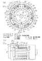
図1(a)はブラシレスモータの模式断面図を示し、図1(b)は図1(a)のIB−IB線での一部断面模式側面図を示す。図5はロータの回転角度とコイルの通電状態との関係を示すグラフである。
【0026】
図1(b)に示すように、ブラシレスモータ11は、モータハウジング12を備え、モータハウジング12は、有底筒状のヨーク13と、エンドフレーム14とを備えている。ヨーク13の底部と、エンドフレーム14とには、各々の中心部に軸受が固設されている。ヨーク13とエンドフレーム14とで形成される空間には、ロータ18が収容されている。ロータ18の回転軸19は、前記両軸受により回転可能に支持されている。
【0027】
図1(a)に示すように、ロータ18のロータコア20は鉄製で、円筒状に形成されており、ロータコア20の周面には、複数の永久磁石が一体回転可能に取り付けられている。この実施形態では、ロータコア20には円弧板状の永久磁石が4個取り付けられている。これらの永久磁石を、第1回転永久磁石21,第2回転永久磁石22,第3回転永久磁石23,第4回転永久磁石24と称する。各第1〜第4回転永久磁石21〜24は、周方向に同じ長さに形成され、隣接するように形成されている。このため、各第1〜第4回転永久磁石21〜24は、ロータ18の中心と両端面とがなす角が90°になっている。図1(a)に示すように、ロータ18をエンドフレーム14側から見た場合、第1〜第4回転永久磁石21〜24は時計方向に順に配置されている。
【0028】
第1〜第4回転永久磁石21〜24は、径方向に極性が変化するように着磁されており、図面では径方向外側の磁極のみ図示し、径方向内側の磁極は図示を省略している。
【0029】
第1回転永久磁石21は、径方向外側がN極になるように配置されている。この実施形態では、第1回転永久磁石21のN極をN1極と称し、第2回転永久磁石22のS極をS1極、第3回転永久磁石23のN極をN2極、第4回転永久磁石24のS極をS2極と称する。
【0030】
第1〜第4回転永久磁石21〜24は、ロータコア20の軸方向長さと同じに形成されている。
図1(a),(b)に示すように、ヨーク13の円筒部13aの内周面には、突起鉄心27が取り付けられている。突起鉄心27は、ヨーク13の周方向に複数配置されている。この実施形態では、6個の突起鉄心27が、ヨーク13の周方向に等角度間隔(60°間隔)で取り付けられている。各突起鉄心27は、基端が円筒部13aの内周面に取り付けられ、先端がロータ18に向けて突出するように形成されている。
【0031】
各突起鉄心27には、それぞれ巻線が巻装されてコイルが形成されている。この実施形態では、図1(a)において左上のコイルを第1コイルL1と称し、他のコイルは、図1(a)において時計方向に順に、第2コイルL2、第3コイルL3、第4コイルL4、第5コイルL5、第6コイルL6と称する。
【0032】
第1コイルL1,第3コイルL3.第5コイルL5は、給電されると径方向内側がN極になり、径方向外側がS極になるように突起鉄心27に巻装されている。逆に、第2コイルL2,第4コイルL4.第6コイルL6は、給電されると径方向内側がS極になり、径方向外側がN極になるように突起鉄心27に巻装されている。
【0033】
各突起鉄心27は、接続鉄心28と一体に形成されている。各接続鉄心28は、ほぼコ字状で、各第1〜第6コイルL1〜L6をそれぞれ覆うように形成されている。接続鉄心28の端部は円筒部13aに対向している。突起鉄心27は、その先端が、接続鉄心28の中央部に連続している。また、ヨーク13の円筒部13aには、各第1〜第6コイルL1〜L6間に円弧板状のインシュレータ29が取り付けられており、接続鉄心28の端部は、インシュレータ29によって円筒部13aと磁気絶縁されている。突起鉄心27、接続鉄心28によって固定鉄心が構成されている。
【0034】
隣り合う接続鉄心28の間には、永久磁石が挟持されている。この実施形態では、第1コイルL1と第2コイルL2とで挟持された永久磁石を第1固定永久磁石31と称し、他の永久磁石は、図1(a)において時計方向に順に、第2固定永久磁石32、第3固定永久磁石33、第4固定永久磁石34、第5固定永久磁石35、第6固定永久磁石36と称する。各第1〜第6固定永久磁石31〜36は、インシュレータ29によって円筒部13aと磁気絶縁されている。また、各第1〜第6固定永久磁石31〜36は、周方向の幅が、接続鉄心28の周方向の幅より小さくなるように形成されている。
【0035】
各第1〜第6固定永久磁石31〜36は、周方向に極性が変化するように形成されている。第1固定永久磁石31は、第1コイルL1側がN極になり、第2コイルL2側がS極になるように形成されている。また、第2固定永久磁石32は、第2コイルL2側がS極になり、第3コイルL3側がN極になるように形成されている。第3固定永久磁石33は、第3コイルL3側がN極になり、第4コイルL4側がS極になるように形成されている。このように、第1〜第6固定永久磁石31〜36は、隣り合う永久磁石同士において、同じ磁極が対向するように配置されている。
【0036】
ヨーク13の円筒部13a、突起鉄心27、接続鉄心28、第1〜第6コイルL1〜L6、第1〜第6固定永久磁石31〜36により、ハイブリッド式磁石が構成されている。また、ハイブリッド式磁石とモータハウジング12とにより、ステータが構成されている。
【0037】
図1(b)に示すように、エンドフレーム14には、ロータ18と対向するように、ブラケットを介してホール素子41が取り付けられている。ブラシレスモータ11は、ロータ18の回転による第1〜第4回転永久磁石21〜24の磁束の変化をホール素子41によって検出し、所定の演算を行うことにより、ロータ18の位置を検出可能になっている。
【0038】
この実施形態では、ロータ18の回転角度θは、図1(a)に示すように、S1極を有する第2回転永久磁石22の中央部が第1固定永久磁石31と対向する状態で、回転角度θ=0°とするように設定されている。第1〜第6コイルL1〜L6は、ホール素子41によって検出されるロータ18の回転位置に基づいて、図5のグラフに示すように給電されるように構成されている。
【0039】
次に、上記のように構成されたブラシレスモータの作用を説明する。
図2に示すように、第1〜第6コイルL1〜L6が給電されていない状態では、第1固定永久磁石31の磁力線は、N極と隣接する接続鉄心28において第1固定永久磁石31側の部分、第1コイルL1が巻装された突起鉄心27、円筒部13a、第2コイルL2が巻装された突起鉄心27、S極と隣接する接続鉄心28において第1固定永久磁石31側の部分を通る閉回路を構成する。このため、第1固定永久磁石31の磁力は、ロータ18側に作用しない。
【0040】
同様に、第2固定永久磁石32の磁力線は、N極と隣接する接続鉄心28において第2固定永久磁石32側の部分、第2コイルL2が巻装された突起鉄心27、円筒部13a、第3コイルL3が巻装された突起鉄心27、S極と隣接する接続鉄心28において第2固定永久磁石32側の部分を通る閉回路を構成する。このため、第2固定永久磁石32の磁力も、ロータ18側に作用しない。また、第2コイルL2が巻装された突起鉄心27内には、第1固定永久磁石31による磁力線と、第2固定永久磁石32による磁力線とが、径方向内側に向かうように通る。
【0041】
同様に、第3固定永久磁石33の磁力線は、第3コイルL3が巻装された突起鉄心27内を径方向外側に向かい、円筒部13aを通って、第4コイルL4が巻装された突起鉄心27内を径方向内側に向かう閉回路を構成し、第3固定永久磁石33の磁力はロータ18側に作用しない。このため、第3コイルL3内の突起鉄心27内には、第2固定永久磁石32による磁力線と、第3固定永久磁石33による磁力線とが、径方向外側に向かうように通る。
【0042】
このように、第1〜第6コイルL1〜L6が給電されていない状態では、各第1〜第6固定永久磁石31〜36の磁力線は、接続鉄心28、突起鉄心27、ヨーク13の円筒部13aを通る閉回路を構成するため、ロータ18側に作用しない。
【0043】
また、第1コイルL1、第3コイルL3、第5コイルL5が巻装された突起鉄心27には、それぞれ固定永久磁石の磁力線が径方向外側に向かうように通る。また、第2コイルL2、第4コイルL4、第6コイルL6内が巻装された突起鉄心27には、それぞれ固定永久磁石の磁力線が径方向内側に向かうように通る。
【0044】
図3に示すように、ロータ18の回転角度が0°の状態では、この回転角度がホール素子41によって検出されることに基づいて、第1コイルL1及び第2コイルL2が給電される。
【0045】
第1コイルL1が給電されて電磁石になると、第1コイルL1の径方向内側がN極になり、径方向外側がS極になるような磁界が発生する。この電磁石による磁界により、第1コイルL1が巻装された突起鉄心27には、図2の場合と逆向きの、径方向内側向きに磁力線が通るようになる。このため、第1及び第6固定永久磁石31,36の磁力線は、第1コイルL1が巻装された突起鉄心27を通る閉回路を構成できなくなり、両磁石のN極から出る磁力線は、第1コイルL1による電磁石の磁力線とともに、ロータ18側に向かう。
【0046】
このため、第1コイルL1を覆う接続鉄心28では、第1コイルL1による電磁石の磁力と、第1及び第6固定永久磁石31,36による磁力とが合計された強力な磁力が、ロータ18側に作用する。
【0047】
また、第2コイルL2が給電されて電磁石になると、第2コイルL2の径方向内側がS極になり、径方向外側がN極になるような磁界が発生する。この電磁石による磁界により、第2コイルL2が巻装された突起鉄心27には、図2の場合と逆向きの、径方向外側向きに磁力線が通るようになる。このため、第1及び第2固定永久磁石31,32の磁力線は、第2コイルL2が巻装された突起鉄心27を通る閉回路を構成できなくなり、両磁石のS極に入る磁力線は、第2コイルL2による電磁石の磁力線とともに、ロータ18側から各S極に入る。
【0048】
このため、第2コイルL2を覆う接続鉄心28でも同様に、第2コイルL2による電磁石の磁力と、第1及び第2固定永久磁石31,32による磁力とが合計された強力な磁力が、ロータ18側に作用する。
【0049】
よって、ロータ18の第2回転永久磁石22におけるS1極では、第2コイルL2側との間に反発力が生じ、第1コイルL1側との間に引張力が生じる。また、第1回転永久磁石21におけるN1極は第1コイルL1側との間に反発力を受け、第3回転永久磁石23におけるN2極は第2コイルL2側との間に引張力を受ける。このように、ロータ18は、電磁石の磁力と固定永久磁石の磁力とが合計された強力な磁力が回転永久磁石に作用することにより、図3中、反時計方向に回転する。
【0050】
図4(a)に示すように、ロータ18の回転角度が30°になり、S1極の中央部が第1コイルL1に対向すると、第1コイルL1が給電されなくなり、第2コイルL2は引き続き給電され、新たに第3コイルL3が給電される。このため、第2及び第3固定永久磁石32,33の磁力線は、第3コイルL3が巻装された突起鉄心27を通る閉回路を構成できなくなり、両磁石のN極から出る磁力線は、第3コイルL3による電磁石の磁力線とともに、ロータ18側に向かう。
【0051】
よって、ロータ18のN2極では、第3コイルL3側との間に反発力が生じ、第2コイルL2側との間に引張力が生じる。また、S1極は第2コイルL2側との間に反発力を受け、S2極は第3コイルL3側との間に引張力を受ける。このため、ロータ18は、停止することなく引き続き回転する。
【0052】
同様に、図4(b)に示すように、ロータ18の回転角度が60°になり、N2極の中央部が第2コイルL2に対向すると、第2コイルL2が給電されなくなり、第3コイルL3は引き続き給電され、新たに第4コイルL4が給電される。このため、第3及び第4固定永久磁石33,34の磁力と、第4コイルL4による磁力とが合計された磁力がロータ18側に作用し、ロータ18は引き続き回転する。
【0053】
同様に、図5のグラフに示すように、同時には2つのコイルが給電され、一つのコイルはロータ18が60°回転する間に連続して給電されるようにして、ロータ18が30°回転するごとに、順次第1〜第6コイルL1〜L6が給電される。上記のようにして、ロータ18は、第1〜第6コイルL1〜L6による電磁石の磁力と、第1〜第6固定永久磁石31〜36の磁力とが合計された強力な磁力によって、連続回転される。
【0054】
また、コイルが第1コイルL1、第2コイルL2、第3コイルL3、…の順に給電されることにより、ロータ51は反時計方向に回転する。
この実施形態によれば、以下のような効果を有する。
【0055】
(1)ブラシレスモータ11は、ステータにハイブリッド式磁石が取り付けられ、ロータ18に第1〜第4回転永久磁石21〜24が取り付けらている。このため、第1〜第6コイルL1〜L6が順次給電されることにより、第1〜第6固定永久磁石31〜36の磁力と、電磁石の磁力とが合計された強力な磁力によって、ロータ18の第1〜第4回転永久磁石21〜24との間で引張力及び反発力を作用させて、ロータ18を回転できる。従って、小型高トルク化を図ることができる。
【0056】
(2)第1〜第6固定永久磁石31〜36と第1〜第6コイルL1〜L6とが周方向に交互に配置されるため、ブラシレスモータ11は径方向においてコンパクト化できる。
【0057】
(3)ロータ18の回転永久磁石の磁極数は周方向に4個で、第1〜第4回転永久磁石21〜24は隣接して配置され、突起鉄心は6個形成されている。このため、効果的にロータ51を回転させることが可能な状態において、最もシンプルで、配置の良い構成にすることができる。
【0058】
(4)第1〜第6固定永久磁石31〜36は、周方向に極性が変化するように配置されている。このため、第1〜第6コイルL1〜L6が給電されていない状態で、第1〜第6固定永久磁石31〜36がロータ18の第1〜第4回転永久磁石21〜24を直接吸引する作用を防止でき、ロータ18に悪影響を及ぼす可能性を低減できる。
【0059】
(5)突起鉄心27と接続鉄心28とが一体に形成されているため、突起鉄心27と接続鉄心28との間で磁束が通りやすくなっている。
(第2の実施形態)
次に、第2の実施形態を図6〜図9に従って説明する。この実施形態では、ロータが突起を備え、ロータに永久磁石が取り付けられていない点が前記実施形態と大きく異なっている。前記実施形態と同様の部分については同一番号を付してその詳細な説明を省略する。
【0060】
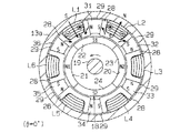
図6は第2の実施形態のブラシレスモータの模式断面図を示し、図9はロータの回転角度とコイルの給電状態との関係を示すグラフである。
図6に示すように、このブラシレスモータのロータ51は、鉄製で、放射状に複数の突起を有するように形成されている。この実施形態では、ロータ51は4個の突起を有しており、断面がほぼ十字状になるように形成されている。各突起は、図6において回転軸19に対して左上に延びる突起を突起R1と称し、時計方向に順に突起R2,R3,R4と称する。突起R1〜R4の径方向外側端部は、円弧状に形成されている。また、ロータ51には永久磁石は取り付けられていない。
【0061】
コイルは、巻装方向は第1の実施形態の第1〜第6コイルL1〜L6と同じに構成されている。この実施形態では、図6において左下のコイルをコイルu1と称し、回転軸19を挟んでコイルu1と対向するコイルをコイルu2と称する。コイルu1の巻線と、コイルu2の巻線とは接続されており、U相を構成する。また、コイルu2に対して時計方向側に隣のコイルをコイルv1、これと対向するコイルをコイルv2、コイルv2に対して時計方向側に隣のコイルをコイルw1、これと対向するコイルをコイルw2と称する。コイルv1,v2、コイルw1,w2もそれぞれ巻線が接続されており、それぞれV相、W相を構成する。このようにコイルは、U相,V相,W相の3相を構成するように形成されている。
【0062】
各突起R1〜R4は、同じ大きさ及び形状に形成されている。各突起R1〜R4の周方向の幅は、接続鉄心28の周方向の幅とほぼ同じに形成されている。また、各突起R1〜R4の周方向の幅は、隣り合う接続鉄心28同士の周方向の端面間の間隔より大きくなっている。
【0063】
このブラシレスモータでは、回転軸19に一体回転するように回転遮光板が取り付けられており、この回転遮光板を挟むように、光電素子と光源との組が、ブラケットを介して複数配置されている。回転遮光板には切欠部が形成されており、回転遮光板の回転によって光電素子の受光状態と遮光状態が切り換えられることにより、ロータの回転位置が検出されるように構成されている。ブラシレスモータは、光電素子によって検出されるロータ51の回転位置に基づいて、U相〜W相の各コイルが、図9のグラフに示すように給電されるように構成されている。この実施形態では、図6に示すようにロータ51の突起R1がコイルw1と対向する場合に、ロータ51の回転角度を0°とするように設定されている。
【0064】
U相〜W相の各コイルが給電されていない状態では、各第1〜第6固定永久磁石31〜36の磁力線は、第1の実施形態と同様に、接続鉄心28、突起鉄心27、ヨーク13の円筒部13aを通る閉回路となるため、各磁石の磁力はロータ51側に作用しない。
【0065】
ロータ51の回転角度θが0°の状態では、ロータ51の突起R1がコイルw1と対向し、突起R3がコイルw2と対向する。また、突起R2は、その一部がコイルu2を覆う接続鉄心28と対向し、突起R4は、その一部がコイルu1を覆う接続鉄心28に対向する。この状態では、ロータ51の回転角度が光電素子によって検出されることに基づいて、U相、即ちコイルu1及びコイルu2が給電される。
【0066】
この給電により、コイルu1による電磁石の磁力と、第4及び第5固定永久磁石34,35の磁力とが合計された強力な磁力によって、突起R4がコイルu1側に引っ張られる。また、コイルu2による電磁石の磁力と、第1及び第2固定永久磁石31,32の磁力とが合計された強力な磁力によって、突起R2がコイルu2側に引っ張られる。このため、ロータ51は、反時計方向に回転する。また、コイルu1、第4及び第5固定永久磁石34,35のN極から出る磁力線は、接続鉄心28を通って突起R4に入り、ロータ51内を通過して、突起R2から、接続鉄心28を通ってコイルu2、第1及び第2固定永久磁石31,32のS極に入る(図7参照)。
【0067】
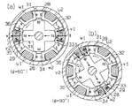
ロータ51の回転角度θが30°になると、突起R4がコイルu1と対向し、突起R2がコイルu2と対向する。また、突起R3の一部がコイルv1を覆う接続鉄心28と対向し、突起R1の一部がコイルv2を覆う接続鉄心28に対向する。回転角度θが30°になったことが光電素子によって検知されると、U相が給電されなくなり、新たにV相が給電される。
【0068】
この給電により、コイルv1による電磁石の磁力と、第2及び第3固定永久磁石32,33の磁力とが合計された磁力によって、突起R3がコイルv1側に引っ張られる。また、コイルv2による電磁石の磁力と、第5及び第6固定永久磁石35,36の磁力とが合計された磁力によって、突起R1がコイルv2側に引っ張られる。このため、ロータ51は、停止することなく引き続き反時計方向に回転する。また、コイルv1、第2及び第3固定永久磁石32,33のN極から出る磁力線は、接続鉄心28を通って突起R3に入り、ロータ51内を通過して、突起R1から、接続鉄心28を通ってコイルv2、第5及び第6固定永久磁石35,36のS極に入る(図8(a)参照)。
【0069】
同様に、ロータ51の回転角度が60°になると、V相が給電されなくなり、新たにW相が給電され、ロータ51が引き続き反時計方向に回転される。コイルw1、第1及び第6固定永久磁石31,36のN極から出る磁力線は、接続鉄心28を通って突起R2に入り、ロータ51内を通過して、突起R4から、接続鉄心28を通ってコイルw2、第3及び第4固定永久磁石33,34のS極に入る(図8(b)参照)。
【0070】
また、ロータ51の回転角度が90°になると、W相が給電されなくなり、再びU相が給電され、ロータ51が引き続き反時計方向に回転される。
このように、図9のグラフに示すように、ロータ51が30°回転するごとに、U、V、W相の給電が順次切り換えられる。よって、ロータ51は、コイルu1〜コイルw2による電磁石の磁力と、第1〜第6固定永久磁石31〜36の磁力とが合計された強力な磁力によって、連続回転される。
【0071】
この実施形態によれば、前記実施形態の(2)、(4)及び(5)の効果の他に、以下のような効果を有する。
(6)ステータには、3相のコイルが設けられたハイブリッド式磁石が取り付けられ、ロータ51には突起R1〜R4が形成されている。このため、3相の各コイルが順次給電されることにより、第1〜第6固定永久磁石31〜36の磁力と、電磁石の磁力とが合計された強力な磁力によって突起R1〜R4を吸引して、ロータ51を回転できる。従って、この場合でも、小型高トルク化を図ることができる。
【0072】
(7)ロータ51の突起R1〜R4の周方向の幅と、接続鉄心28の周方向の幅とは、ほぼ同じ程度に形成されている。このため、突起R1〜R4が電磁石に最も引っ張られた状態では、突起R1〜R4と接続鉄心28とは、周方向においてほぼ過不足なく対向する。よって、突起R1〜R4と、接続鉄心28との間において磁束の漏れが低減され、高トルク化を効果的に図ることができる。
【0073】
(8)ロータ51の突起R1〜R4の周方向の幅は、隣り合う接続鉄心28の周方向の端面間より大きく形成されている。このため、突起と接続鉄心28との少なくとも一部で対向する部分に磁束を通過させることにより、常にロータ51に引張力を働かせ続けることができ、ロータ51をスムーズに回転できる。
【0074】
(9)ロータ51の突起R1〜R4の数は4個で、ステータの突起鉄心27は6個形成されており、コイルは3相に形成されているため、効果的にロータ51を回転可能に形成するうえで、最もシンプルで、配置の良い構成にすることができる。
【0075】
(10)コイルu1,v1,w1は、給電された状態で径方向内側がN極になるように巻装され、それぞれに対向するコイルu2,v2,w2は、給電された状態で径方向内側がS極になるように巻装されている。また、ロータ51は、突起が回転軸19を挟んで対向するように形成されている。このため、各コイルu1,v1,w1から出る磁力線が、ロータ51の突起R1,R3又は突起R2,R4を通って、それぞれコイルu2,v2,w2に入る。よって、磁束が通りやすくなっている
なお、実施形態は上記実施形態に限定されるものではなく、例えば以下のように変更してもよい。
【0076】
・突起鉄心27と接続鉄心28とが一体に形成されることに限られず、例えば突起鉄心27と接続鉄心28とをそれぞれ別に形成し、突起鉄心27の先端に接続鉄心28の中央部を当接した構成にしてもよい。
【0077】
・第1の実施形態において、第1〜第4回転永久磁石21〜24は、隣接するように形成されることに限られず、例えば、各第1〜第4回転永久磁石間にわずかに隙間が存在するように形成してもよい。
【0078】
・第1の実施形態において、ホール素子41は1個設けられることに限られず、複数設けてもよい。
・コイル及び固定永久磁石の数は、それぞれ6個であることに限られず、例えば6以外の偶数であってもよく、例えば2個、4個、8個等にしてもよい。
【0079】
・第1の実施形態において、ロータに取り付けられる固定永久磁石の数は、4個であることに限られず、例えば4以外の偶数であってもよく、例えば2個、6個、8個等にしてもよい。
【0080】
・第2の実施形態において、ロータの突起の数は、4個であることに限られず、例えば4以外の偶数であってもよく、例えば2個、6個、8個等にしてもよい。
【0081】
・第1の実施形態において、コイルは第1コイルL1、第2コイルL2、第3コイルL3、…の順に給電されて、ロータ51を反時計方向に回転させることに限られない。例えば、θ=0°の状態において、第4及び第5コイルL4,L5に給電すると、第4コイルL4の径方向内側がN極、第5コイルL5の径方向内側がS極になることにより、ロータ18のS2極との間にそれぞれ引張力、反発力が作用するため、ロータ18は時計方向に回転する。次に、30°回転したときに、第5コイルL5への給電をやめ、第4コイルL4に引き続き給電し、新たに第3コイルL3に給電すると、N2極と第3コイルL3との間に反発力が作用し、N2極と第4コイルL4との間に引張力が作用するため、ロータ18は引き続き時計方向に回転する。このように、第6コイルL6、第5コイルL5、第4コイルL4、第3コイルL3、…の順に給電して、ロータ18を時計方向に回転させてもよい。
【0082】
・第2の実施形態において、コイルはU相、V相、W相の順に給電されて、ロータ51を反時計方向に回転させることに限られない。例えば、θ=0°の状態において、V相のコイルに給電すると、突起R2,R4はそれぞれコイルv1,v2側に引っ張られるため、ロータ51は時計方向に回転する。次に、30°回転するごとにU相、W相の順に給電すると、ロータ51は引き続き時計方向に回転する。このため、コイルをW相、V相、U相の順に給電して、ロータ51を時計方向に回転させてもよい。なお、この場合、W相、U相をそれぞれ新たにU相、W相と称すると、U相、V相、W相の順に給電してロータ51を時計方向に回転させることになる。
【0083】
・第1及び第2の実施形態において、ロータの位置検出は、例えばロータリエンコーダによって位置検出するように構成してもよい。
・第2の実施形態において、ロータ51の位置検出は、回転遮光板と光電素子との組み合わせによって行われることに限られない。例えば、エンドフレーム14とヨーク13の底部との一方に光源を取り付けるとともに、他方に光電素子を取り付け、ロータ51の回転によって光源と光電素子との間に突起R1〜R4が位置するときに遮光状態になり、突起R1〜R4間の間隙が位置するときに受光状態になるように構成する。この光源と光電素子の組を複数取り付け、ロータ51の位置検出を可能に構成してもよい。
【0084】
・第1の実施形態において、ロータ18の位置検出は、例えば第2の実施形態と同様に、回転遮光板と光電素子との組み合わせによってロータ18の位置検出を行うように構成してもよい。
【0085】
・第2の実施形態において、ロータ51は、鉄製であることに限られず、例えば他の強磁性体で形成してもよい。
・第1の実施形態において、ロータコア20は、鉄製であることに限られず、例えば他の強磁性体で形成してもよい。
【0086】
・ブラシレスモータは、インナロータ型であることに限られず、例えばアウタロータ型でもよい。
上記各実施形態から把握できる技術的思想について、以下に追記する。
【0087】
(1) 請求項1又は請求項2に記載の発明において、前記ロータに取り付けられる前記永久磁石は、周方向に隣接して設けられている。
(2) 請求項1、請求項2及び(1)のいずれか一つに記載の発明において、前記突起鉄心と前記接続鉄心とが一体に形成されている。
【0088】
(3) 請求項3〜請求項6のいずれか一項に記載の発明において、前記ロータは鉄製である。
【0089】
【発明の効果】
以上詳述したように、請求項1〜請求項6に記載の発明によれば、小型高トルク化を図るとともに、径方向においてコンパクト化できる。
【図面の簡単な説明】
【図1】(a)はブラシレスモータの模式断面図、(b)は(a)のIB−IB線での一部断面模式側面図。
【図2】作用を示す模式断面図。
【図3】作用を示す模式断面図。
【図4】作用を示す模式断面図。
【図5】ロータの回転角度とコイルの給電状態との関係を示すグラフ。
【図6】第2の実施形態のブラシレスモータの模式断面図。
【図7】作用を示す模式断面図。
【図8】作用を示す模式断面図。
【図9】ロータの回転角度とコイルの給電状態との関係を示すグラフ。
【図10】従来のハイブリッド式磁石を示す模式図。
【符号の説明】
11…ブラシレスモータ、18,51…ロータ、21〜24…第1〜第4回転永久磁石、R1〜R4…突起、12…ステータを構成するモータハウジング、13a…ハイブリッド磁石を構成する円筒部、27…同じく突起鉄心、28…同じく接続鉄心、31〜36…同じく第1〜第6固定永久磁石、L1〜L6…同じく第1〜第6コイル、u1〜w2…同じくコイル。[0001]
BACKGROUND OF THE INVENTION
The present invention relates to a brushless motor.
[0002]
[Prior art]
Currently, development of motors is diverse, for example, development of micro motors, higher accuracy of stepping motors, reduction of power consumption, and higher torque. In particular, small motors with low power consumption and high torque are widely used in the fields of automobiles, OA equipment, vending equipment, medical / welfare equipment, and the like.
[0003]
Usually, most of the motors used in these are motors using permanent magnets, and since the technology is quite mature, it is difficult to achieve dramatic improvements in efficiency and size and torque.
[0004]
For example, a motor using a hybrid magnet is known in order to reduce the size and increase the torque. For example, Japanese Patent Application Laid-Open No. 2000-150228 discloses a stepping motor including a hybrid magnet including both a coil and a permanent magnet. As shown in FIG. 10, in the
[0005]
[Problems to be solved by the invention]
However, in the
[0006]
The present invention has been made in view of the above circumstances, and an object of the present invention is to provide a brushless motor capable of reducing the size and increasing the torque and reducing the size in the radial direction.
[0007]
[Means for Solving the Problems]
In order to achieve the above object, the invention according to
[0008]
According to this invention, in a state where the coil is not supplied with power, the magnetic lines of force of the fixed permanent magnet of the hybrid magnet constitute a closed circuit passing through the connecting iron core, the protruding iron core, and the cylindrical portion, so that no magnetic force acts on the rotor side. .
[0009]
In a state where the coil is supplied with power, the magnetic field lines of the fixed permanent magnet are bent by the magnetic force of the electromagnet and directed toward the rotor. For this reason, when the coil is fed, a strong magnetic force, which is the sum of the magnetic force of the electromagnet and the magnetic force of the fixed permanent magnet, acts on the rotor side from the hybrid magnet. With this strong magnetic force, the coils are sequentially fed, whereby the permanent magnet of the rotor receives a tensile force and a repulsive force, and the rotor is rotated.
[0010]
I want to make the magnetic flux density of the brushless motor stator as strong as possible. In addition, when the amount of current is increased, heat generation increases and energy loss occurs. Therefore, by providing a hybrid magnet having a fixed permanent magnet, it is possible to obtain a brushless motor stator that is strong in torque and generates little heat.
[0011]
Further, since the fixed permanent magnet and the coil are arranged in the circumferential direction, the size is reduced in the radial direction. Therefore, it is possible to reduce the size and increase the torque, and to reduce the size in the radial direction.
[0012]
Further, when the inner peripheral surface of the cylindrical portion faces the rotor, the brushless motor is an inner rotor type. On the contrary, when the outer peripheral surface of the cylindrical portion faces the rotor, the brushless motor is an outer rotor type.
[0013]
The invention according to
According to the present invention, power is supplied to two adjacent coils, and a predetermined permanent magnet of the rotor is rotated by a repulsive force and a tensile force. It is located between two coils that can apply a tensile force and a repulsive force to the permanent magnet. For this reason, by next feeding these two coils, the rotor can be effectively rotated, and the simplest and best arrangement can be achieved.
[0014]
According to a third aspect of the present invention, there is provided a rotor having a plurality of radial projections, a cylindrical portion facing one of the outer peripheral surface and the inner peripheral surface of the rotor, and a circumferential direction on a surface of the cylindrical portion facing the rotor. A plurality of fixed iron cores, coils wound around the fixed iron cores and sequentially fed so as to rotate the rotor, and fixedly arranged so that the polarity changes in the circumferential direction between the fixed iron cores A brushless motor comprising a stator having a hybrid magnet comprising a permanent magnet, wherein the fixed iron core is formed such that a base end is connected to the cylindrical portion and a tip protrudes toward the rotor. The protruding iron core around which the coil is wound, and a connecting iron core that is formed in a substantially U shape and covers the coil, and an end portion of which faces the cylindrical portion, and the end portion of the connecting iron core is the cylindrical portion And magnetism Insulated, the fixed permanent magnet, at its ends, abuts on the connecting iron core adjacent the said fixed permanent magnets adjacent same magnetic poles is summarized in that arranged so as to face.
[0015]
According to the present invention, in the state where the coil is not supplied with power, the magnetic lines of force of the fixed permanent magnet constitute a closed circuit passing through the connecting iron core, the protruding iron core, and the cylindrical portion, as in the first aspect of the invention. Magnetic force does not act on the rotor side. Further, in a state where the coil is fed, the magnetic lines of force of the fixed permanent magnet are bent by the magnetic force of the electromagnet and directed toward the rotor side. For this reason, when the coil is fed, a strong magnetic force, which is the sum of the magnetic force of the electromagnet and the magnetic force of the fixed permanent magnet, acts on the rotor side from the hybrid magnet. Due to the strong magnetic force, the protrusions of the rotor receive a tensile force, and the rotor is rotated by sequentially supplying power to the coils.
[0016]
Thus, by providing a hybrid magnet in the stator, torque is strong and heat generation can be reduced. Therefore, even if a permanent magnet is not provided in the rotor, a small and high torque can be achieved. Moreover, since the rotor is not provided with a permanent magnet, the manufacturing cost can be reduced accordingly.
[0017]
Further, since the fixed permanent magnet and the coil are arranged in the circumferential direction, the size is reduced in the radial direction. Therefore, it is possible to reduce the size and increase the torque, and to reduce the size in the radial direction. The brushless motor is an inner rotor type when the inner peripheral surface of the cylindrical portion faces the rotor, and the outer rotor type when the outer peripheral surface of the cylindrical portion faces the rotor.
[0018]
The gist of the invention according to claim 4 is that, in the invention according to
[0019]
According to this invention, when the rotor protrusion is pulled by the magnetic force of the hybrid magnet and the rotor protrusion faces the connecting iron core that covers the coil in the state of the electromagnet, the rotor iron core and the connecting iron core are Opposite in almost no direction. For this reason, the leakage of magnetic flux is reduced between the protrusion of the rotor and the connecting iron core, and a high torque can be effectively achieved.
[0020]
The invention according to
[0021]
According to this invention, when a certain protrusion of the rotor is pulled by the magnetic force of the hybrid magnet and the rotor rotates, and this protrusion faces the connecting iron core that covers the coil in the state of the electromagnet, another protrusion of the rotor is It faces another connecting iron core in a part in the circumferential direction. For this reason, next, when the coil covered with the other connecting iron core is fed, the magnetic flux passes between the other protrusion and the other connecting iron core in a part of the opposing circumferential direction. The protrusion is pulled and the rotor continues to rotate. Therefore, the tensile force can be continuously applied to the rotor, and the rotor can be rotated smoothly.
[0022]
The invention according to claim 6 is the invention according to any one of
[0023]
According to the present invention, when a coil of a certain phase is supplied with power, and the two protrusions of the rotor are pulled and opposed to the two coil sides constituting this phase, the remaining two protrusions of the rotor are respectively different from each other. Located between the coils. For this reason, when the coil of another phase is supplied with power next time, the rotor can be effectively rotated, and the simplest arrangement can be obtained.
[0024]
DETAILED DESCRIPTION OF THE INVENTION
(First embodiment)
Hereinafter, a first embodiment in which the present invention is embodied in an inner rotor type brushless motor will be described with reference to FIGS.
[0025]
1A is a schematic cross-sectional view of a brushless motor, and FIG. 1B is a partial cross-sectional schematic side view taken along line IB-IB in FIG. FIG. 5 is a graph showing the relationship between the rotation angle of the rotor and the energized state of the coil.
[0026]
As shown in FIG. 1B, the
[0027]
As shown in FIG. 1A, the
[0028]
The first to fourth rotating
[0029]
The 1st rotation
[0030]
The first to fourth rotating
As shown in FIGS. 1A and 1B, a protruding
[0031]
Each protruding
[0032]
1st coil L1, 3rd coil L3. The fifth coil L5 is wound around the protruding
[0033]
Each protruding
[0034]
A permanent magnet is sandwiched between adjacent connecting
[0035]
Each of the first to sixth fixed
[0036]
A hybrid magnet is configured by the
[0037]
As shown in FIG. 1B, a
[0038]
In this embodiment, the rotation angle θ of the
[0039]
Next, the operation of the brushless motor configured as described above will be described.
As shown in FIG. 2, in a state where the first to sixth coils L1 to L6 are not supplied with power, the magnetic lines of force of the first fixed
[0040]
Similarly, the magnetic lines of force of the second fixed
[0041]
Similarly, the magnetic lines of force of the third fixed
[0042]
Thus, in the state where the first to sixth coils L1 to L6 are not supplied with power, the magnetic lines of force of the first to sixth fixed
[0043]
Further, the magnetic lines of force of the fixed permanent magnets pass through the protruding
[0044]
As shown in FIG. 3, when the rotation angle of the
[0045]
When the first coil L1 is fed to become an electromagnet, a magnetic field is generated such that the radially inner side of the first coil L1 becomes the N pole and the radially outer side becomes the S pole. Due to the magnetic field generated by the electromagnet, magnetic lines of force pass through the protruding
[0046]
For this reason, in the connecting
[0047]
Further, when the second coil L2 is fed to become an electromagnet, a magnetic field is generated such that the radially inner side of the second coil L2 becomes the S pole and the radially outer side becomes the N pole. Due to the magnetic field generated by the electromagnet, magnetic field lines pass through the protruding
[0048]
For this reason, the connecting
[0049]
Therefore, in the S1 pole in the second rotating
[0050]
As shown in FIG. 4A, when the rotation angle of the
[0051]
Therefore, a repulsive force is generated between the N2 pole of the
[0052]
Similarly, as shown in FIG. 4B, when the rotation angle of the
[0053]
Similarly, as shown in the graph of FIG. 5, two coils are fed at the same time, and one coil is continuously fed while the
[0054]
Further, when the coils are fed in the order of the first coil L1, the second coil L2, the third coil L3,..., The
According to this embodiment, the following effects are obtained.
[0055]
(1) In the
[0056]
(2) Since the first to sixth fixed
[0057]
(3) The number of magnetic poles of the rotating permanent magnet of the
[0058]
(4) The first to sixth fixed
[0059]
(5) Since the protruding
(Second Embodiment)
Next, a second embodiment will be described with reference to FIGS. In this embodiment, the rotor is provided with protrusions, and the rotor is not attached with a permanent magnet. The same parts as those in the above embodiment are denoted by the same reference numerals, and detailed description thereof is omitted.
[0060]
FIG. 6 is a schematic cross-sectional view of the brushless motor according to the second embodiment, and FIG. 9 is a graph showing the relationship between the rotation angle of the rotor and the power supply state of the coil.
As shown in FIG. 6, the
[0061]
The winding direction of the coil is the same as that of the first to sixth coils L1 to L6 of the first embodiment. In this embodiment, the lower left coil in FIG. 6 is referred to as a coil u1, and the coil facing the coil u1 across the rotating
[0062]
Each protrusion R1-R4 is formed in the same magnitude | size and shape. The circumferential width of each of the protrusions R <b> 1 to R <b> 4 is formed substantially the same as the circumferential width of the connecting
[0063]
In this brushless motor, a rotating light shielding plate is attached so as to rotate integrally with the rotating
[0064]
In the state where the coils of the U-phase to W-phase are not supplied with power, the magnetic lines of force of the first to sixth fixed
[0065]
When the rotation angle θ of the
[0066]
By this power supply, the protrusion R4 is pulled toward the coil u1 by the strong magnetic force obtained by adding the magnetic force of the electromagnet by the coil u1 and the magnetic force of the fourth and fifth fixed
[0067]
When the rotation angle θ of the
[0068]
By this power supply, the projection R3 is pulled toward the coil v1 by the magnetic force obtained by adding the magnetic force of the electromagnet by the coil v1 and the magnetic force of the second and third fixed
[0069]
Similarly, when the rotation angle of the
[0070]
When the rotation angle of the
In this way, as shown in the graph of FIG. 9, every time the
[0071]
According to this embodiment, in addition to the effects (2), (4) and (5) of the above embodiment, the following effects are obtained.
(6) A hybrid magnet provided with a three-phase coil is attached to the stator, and protrusions R1 to R4 are formed on the
[0072]
(7) The circumferential width of the protrusions R1 to R4 of the
[0073]
(8) The circumferential width of the protrusions R <b> 1 to R <b> 4 of the
[0074]
(9) Since the number of the protrusions R1 to R4 of the
[0075]
(10) The coils u1, v1, and w1 are wound so that the radially inner side is N-pole when power is supplied, and the coils u2, v2, and w2 that face each other are radially inner when supplied with power. Is wound to be the S pole. The
In addition, embodiment is not limited to the said embodiment, For example, you may change as follows.
[0076]
The protruding
[0077]
In the first embodiment, the first to fourth rotating
[0078]
In the first embodiment, the number of
The number of coils and fixed permanent magnets is not limited to six each, and may be an even number other than six, for example, two, four, eight, etc.
[0079]
In the first embodiment, the number of fixed permanent magnets attached to the rotor is not limited to four, and may be an even number other than four, for example, two, six, eight, etc. May be.
[0080]
In the second embodiment, the number of protrusions of the rotor is not limited to four, and may be an even number other than 4, for example, 2, 6, 8, or the like.
[0081]
-In 1st Embodiment, a coil is electrically fed in order of 1st coil L1, 2nd coil L2, 3rd coil L3, ..., and is not restricted to rotating the
[0082]
-In 2nd Embodiment, a coil is electrically supplied in order of U phase, V phase, and W phase, and is not restricted to rotating the
[0083]
In the first and second embodiments, the rotor position may be detected by, for example, a rotary encoder.
In the second embodiment, the position detection of the
[0084]
In the first embodiment, the position detection of the
[0085]
In the second embodiment, the
In the first embodiment, the
[0086]
The brushless motor is not limited to the inner rotor type, and may be an outer rotor type, for example.
The technical idea that can be grasped from each of the above embodiments will be described below.
[0087]
(1) In invention of
(2) In the invention according to any one of
[0088]
(3) In the invention according to any one of
[0089]
【The invention's effect】
As described in detail above, according to the inventions described in
[Brief description of the drawings]
1A is a schematic cross-sectional view of a brushless motor, and FIG. 1B is a partial cross-sectional schematic side view taken along line IB-IB in FIG.
FIG. 2 is a schematic cross-sectional view showing the operation.
FIG. 3 is a schematic cross-sectional view showing the operation.
FIG. 4 is a schematic cross-sectional view showing the operation.
FIG. 5 is a graph showing a relationship between a rotation angle of a rotor and a power supply state of a coil.
FIG. 6 is a schematic cross-sectional view of a brushless motor according to a second embodiment.
FIG. 7 is a schematic cross-sectional view showing the operation.
FIG. 8 is a schematic cross-sectional view showing the operation.
FIG. 9 is a graph showing the relationship between the rotation angle of the rotor and the power supply state of the coil.
FIG. 10 is a schematic view showing a conventional hybrid magnet.
[Explanation of symbols]
DESCRIPTION OF
Claims (6)
前記ロータと外周面及び内周面の一方が対向する円筒部と、前記円筒部の前記ロータと対向する面において周方向に複数設けられた固定鉄心と、前記固定鉄心に巻装され、前記ロータが回転するように順次給電されるコイルと、前記固定鉄心間に、周方向に極性が変化するように配置された固定永久磁石とからなるハイブリッド式磁石を備えたステータとからなるブラシレスモータであって、
前記固定鉄心は、基端が前記円筒部と接続するとともに先端が前記ロータに向けて突出するように形成されて前記コイルが巻装された突起鉄心と、ほぼコ字状に形成されて前記コイルを覆い、端部が前記円筒部と対向する接続鉄心とからなり、
前記接続鉄心の端部は、前記円筒部と磁気絶縁され、前記固定永久磁石は、その両端において、隣り合う前記接続鉄心に当接され、隣り合う前記固定永久磁石は、同じ磁極同士が対向するように配置されたことを特徴とするブラシレスモータ。A plurality of rotors arranged in the circumferential direction so that adjacent magnetic poles are different from each other, and permanent magnets magnetized so that the polarity changes in the radial direction;
A cylindrical portion facing one of the outer peripheral surface and the inner peripheral surface of the rotor, a plurality of fixed iron cores provided in a circumferential direction on a surface of the cylindrical portion facing the rotor, and the rotor wound around the fixed iron core; A brushless motor comprising a coil that is sequentially fed so as to rotate, and a stator having a hybrid magnet that is arranged between the fixed iron cores and a fixed permanent magnet that is arranged so that the polarity changes in the circumferential direction. And
The fixed iron core is formed in a substantially U-shape with a protruding iron core formed so that a base end is connected to the cylindrical portion and a front end protrudes toward the rotor and the coil is wound. And the end part is composed of a connecting iron core facing the cylindrical part,
The end of the connection iron core is magnetically insulated from the cylindrical portion, the fixed permanent magnet is abutted against the adjacent connection iron core at both ends thereof, and the same fixed magnetic pole faces the adjacent fixed permanent magnet. A brushless motor characterized by being arranged as described above.
前記ロータと外周面及び内周面の一方が対向する円筒部と、前記円筒部の前記ロータと対向する面において周方向に複数設けられた固定鉄心と、前記固定鉄心に巻装され、前記ロータが回転するように順次給電されるコイルと、前記固定鉄心間に、周方向に極性が変化するように配置された固定永久磁石とからなるハイブリッド式磁石を備えたステータとからなるブラシレスモータであって、
前記固定鉄心は、基端が前記円筒部と接続するとともに先端が前記ロータに向けて突出するように形成されて前記コイルが巻装された突起鉄心と、ほぼコ字状に形成されて前記コイルを覆い、端部が前記円筒部と対向する接続鉄心とからなり、
前記接続鉄心の端部は、前記円筒部と磁気絶縁され、前記固定永久磁石は、その両端において、隣り合う前記接続鉄心に当接され、隣り合う前記固定永久磁石は、同じ磁極同士が対向するように配置されたことを特徴とするブラシレスモータ。A rotor having a plurality of radial projections;
A cylindrical portion facing one of the outer peripheral surface and the inner peripheral surface of the rotor, a plurality of fixed iron cores provided in a circumferential direction on a surface of the cylindrical portion facing the rotor, and the rotor wound around the fixed iron core; A brushless motor comprising a coil that is sequentially fed so as to rotate, and a stator having a hybrid magnet that is arranged between the fixed iron cores and a fixed permanent magnet that is arranged so that the polarity changes in the circumferential direction. And
The fixed iron core is formed in a substantially U-shape with a protruding iron core formed so that a base end is connected to the cylindrical portion and a front end protrudes toward the rotor and the coil is wound. And the end part is composed of a connecting iron core facing the cylindrical part,
The end of the connection iron core is magnetically insulated from the cylindrical portion, the fixed permanent magnet is abutted against the adjacent connection iron core at both ends thereof, and the same fixed magnetic pole faces the adjacent fixed permanent magnet. A brushless motor characterized by being arranged as described above.
Priority Applications (1)
| Application Number | Priority Date | Filing Date | Title |
|---|---|---|---|
| JP2001341064A JP3798677B2 (en) | 2001-11-06 | 2001-11-06 | Brushless motor |
Applications Claiming Priority (1)
| Application Number | Priority Date | Filing Date | Title |
|---|---|---|---|
| JP2001341064A JP3798677B2 (en) | 2001-11-06 | 2001-11-06 | Brushless motor |
Publications (2)
| Publication Number | Publication Date |
|---|---|
| JP2003153513A JP2003153513A (en) | 2003-05-23 |
| JP3798677B2 true JP3798677B2 (en) | 2006-07-19 |
Family
ID=19155170
Family Applications (1)
| Application Number | Title | Priority Date | Filing Date |
|---|---|---|---|
| JP2001341064A Expired - Fee Related JP3798677B2 (en) | 2001-11-06 | 2001-11-06 | Brushless motor |
Country Status (1)
| Country | Link |
|---|---|
| JP (1) | JP3798677B2 (en) |
Cited By (1)
| Publication number | Priority date | Publication date | Assignee | Title |
|---|---|---|---|---|
| CN104617693A (en) * | 2013-11-04 | 2015-05-13 | 罗伯特·博世有限公司 | Motor component used for a motor and method for manufacturing the same |
Families Citing this family (6)
| Publication number | Priority date | Publication date | Assignee | Title |
|---|---|---|---|---|
| JPS5990968A (en) * | 1982-11-17 | 1984-05-25 | Fuji Electric Co Ltd | Light-emitting and receiving unified element |
| JP4383058B2 (en) * | 2003-01-22 | 2009-12-16 | 株式会社ゲネシス | Reluctance motor |
| JP4675647B2 (en) * | 2005-03-03 | 2011-04-27 | 株式会社ダイヤメット | Stator, core for rotating machine and rotating machine |
| JP2008069964A (en) * | 2006-08-18 | 2008-03-27 | Toru Masuzawa | Hybrid magnetic bearing |
| US10541593B2 (en) * | 2013-11-20 | 2020-01-21 | Shanshan Dai | AC permanent-magnet switched reluctance motor |
| JP7778184B2 (en) * | 2023-08-18 | 2025-12-01 | シナノケンシ株式会社 | Interaction force control device, electromagnetic brake equipped with the same, and rotating electric machine equipped with the same |
-
2001
- 2001-11-06 JP JP2001341064A patent/JP3798677B2/en not_active Expired - Fee Related
Cited By (2)
| Publication number | Priority date | Publication date | Assignee | Title |
|---|---|---|---|---|
| CN104617693A (en) * | 2013-11-04 | 2015-05-13 | 罗伯特·博世有限公司 | Motor component used for a motor and method for manufacturing the same |
| CN104617693B (en) * | 2013-11-04 | 2019-07-05 | 罗伯特·博世有限公司 | Method for the electric machine assembly of motor and for manufacturing such electric machine assembly |
Also Published As
| Publication number | Publication date |
|---|---|
| JP2003153513A (en) | 2003-05-23 |
Similar Documents
| Publication | Publication Date | Title |
|---|---|---|
| EP1624555A2 (en) | Axial-gap dynamo-electric machine | |
| US20070018520A1 (en) | Motor/generator to reduce cogging torque | |
| US6563248B2 (en) | Hybrid-magnet DC motor | |
| JP5290795B2 (en) | Brush-fed hybrid excitation motor and driving method of brush-fed hybrid excitation motor | |
| WO2006068038A1 (en) | Inductor type synchronizer | |
| JP3798677B2 (en) | Brushless motor | |
| JP2007236073A (en) | Hybrid rotating electric machine | |
| JP2003088078A (en) | Brushless dc motor | |
| JP7193422B2 (en) | Rotating electric machine and manufacturing method of rotating electric machine | |
| JP3857846B2 (en) | Condenser motor | |
| US20090051253A1 (en) | Printing Machine or Electrical Machine for a Printing Machine | |
| US7679256B2 (en) | Rotary electric machine | |
| JP4823425B2 (en) | DC motor | |
| JP2003153515A (en) | Brushless motor | |
| JP3737750B2 (en) | Hybrid magnet type DC machine | |
| JP3776721B2 (en) | DC motor and armature structure thereof | |
| JP3655201B2 (en) | Hybrid magnet type DC machine | |
| JP3591660B2 (en) | Three-phase claw pole type permanent magnet type rotating electric machine | |
| JP2003047225A (en) | Hybrid dc motor | |
| KR100692386B1 (en) | Single Phase Sensorless Non-Commutator DC Power Motor Assembly with Outer Ring Driven Rotor | |
| WO2008055416A1 (en) | Radial serial connected rotating motor | |
| JPS6122553B2 (en) | ||
| JP2004007968A (en) | Hybrid magnet type dc machine | |
| JP2002204554A5 (en) | ||
| JP3109022B2 (en) | Inductor type electric motor |
Legal Events
| Date | Code | Title | Description |
|---|---|---|---|
| TRDD | Decision of grant or rejection written | ||
| A01 | Written decision to grant a patent or to grant a registration (utility model) |
Free format text: JAPANESE INTERMEDIATE CODE: A01 Effective date: 20060418 |
|
| A61 | First payment of annual fees (during grant procedure) |
Free format text: JAPANESE INTERMEDIATE CODE: A61 Effective date: 20060420 |
|
| R150 | Certificate of patent or registration of utility model |
Free format text: JAPANESE INTERMEDIATE CODE: R150 |
|
| FPAY | Renewal fee payment (event date is renewal date of database) |
Free format text: PAYMENT UNTIL: 20090428 Year of fee payment: 3 |
|
| FPAY | Renewal fee payment (event date is renewal date of database) |
Free format text: PAYMENT UNTIL: 20100428 Year of fee payment: 4 |
|
| FPAY | Renewal fee payment (event date is renewal date of database) |
Free format text: PAYMENT UNTIL: 20100428 Year of fee payment: 4 |
|
| FPAY | Renewal fee payment (event date is renewal date of database) |
Free format text: PAYMENT UNTIL: 20110428 Year of fee payment: 5 |
|
| FPAY | Renewal fee payment (event date is renewal date of database) |
Free format text: PAYMENT UNTIL: 20120428 Year of fee payment: 6 |
|
| FPAY | Renewal fee payment (event date is renewal date of database) |
Free format text: PAYMENT UNTIL: 20130428 Year of fee payment: 7 |
|
| FPAY | Renewal fee payment (event date is renewal date of database) |
Free format text: PAYMENT UNTIL: 20130428 Year of fee payment: 7 |
|
| FPAY | Renewal fee payment (event date is renewal date of database) |
Free format text: PAYMENT UNTIL: 20140428 Year of fee payment: 8 |
|
| LAPS | Cancellation because of no payment of annual fees |