JP3795656B2 - Window lock device - Google Patents
Window lock device Download PDFInfo
- Publication number
- JP3795656B2 JP3795656B2 JP00221198A JP221198A JP3795656B2 JP 3795656 B2 JP3795656 B2 JP 3795656B2 JP 00221198 A JP00221198 A JP 00221198A JP 221198 A JP221198 A JP 221198A JP 3795656 B2 JP3795656 B2 JP 3795656B2
- Authority
- JP
- Japan
- Prior art keywords
- lever
- lock
- link
- end side
- window
- Prior art date
- Legal status (The legal status is an assumption and is not a legal conclusion. Google has not performed a legal analysis and makes no representation as to the accuracy of the status listed.)
- Expired - Fee Related
Links
Images


Description
【0001】
【発明の属する技術分野】
本発明は、窓の開口縁部に基端部側が回転可能に設けられたウィンドウガラスの回転端部側に取り付けられる第1のブラケットと、該第1のブラケットに基端部側が回転可能に設けられるレバーと、該レバーの回転端部側に一方の端部側が回転可能に設けられるリンクと、該リンクの他方の端部側が回転可能に設けられ、窓の開口縁部に取り付けられる第2のブラケットとからなるウィンドウロック装置に関する。
【0002】
【従来の技術】
自動車のクォータウィンドウ等には、クォータウィンドウガラスが開閉可能に設けられ、更に、閉状態にあるクォータウィンドウの開方向の移動を禁止するウィンドウロック装置が設けられている。
【0003】
図6は、このウィンドウロック装置の一例を示す構成図で、(a)図はウィンドウガラスが閉状態にある時を示す図、(b)図はウィンドウガラスが開状態の時をそれぞれ示している。
【0004】
図において、窓2の開口縁部に基端部側が回転可能に設けられたウィンドウガラス1の回転端部側は、第1のブラケット3が取り付けられている。この第1のブラケット3には、レバー5の基端部側が回転可能に取り付けられている。
【0005】
レバー5の回転端部側には、リンク7の一方の端部側が回転可能に取り付けられている。
一方、窓2の開口縁部(ボデー)10には、第2のブラケット9が取り付けられ、この第2のブラケット9には、リンク7の他方の端部側が回転可能に取り付けられている。
【0006】
次に、上記構成の動作を説明する。(a)図に示す状態は、ウィンドウガラス1が閉状態の時を示している。ここで、レバー5を矢印I方向に引くと、ロックが解除され、その後、レバー5を車外へ押すことによりウィンドウガラス1の回転端部側が車外へ開いた(b)図に示す状態となる。
【0007】
又、ウィンドウガラス1を閉じる場合には、(b)図の状態からレバー5を矢印II方向へ引き、ウィンドウガラス1を閉じ、更に、レバー5を反矢印II方向に押すことにより、(a)図に示すロック状態に戻る。
【0008】
【発明が解決しようとする課題】
しかし、上記構成のロック装置が図6(a)に示すロック状態にある時、車外からウィンドウガラス1と開口縁部10との隙間Sより針金等を用いて、レバー5を矢印I方向に押すことにより、レバー5が矢印I方向に回転操作でき、容易にウィンドウガラス1を開けることができる問題点がある。
【0009】
従って、車両内の物品や車両が盗難される問題点がある。
本発明は、上記問題点に鑑みてなされたもので、その目的は、車外よりロック解除されにくく、盗難を防止できるウィンドウロック装置を提供することにある。
【0010】
【課題を解決するための手段】
上記課題を解決する請求項1記載の発明は、窓の開口縁部に基端部側が回転可能に設けられたウィンドウガラスの回転端部側に取り付けられる第1のブラケットと、該第1のブラケットに基端部側が回転可能に設けられるレバーと、該レバーの回転端部側に一方の端部側が回転可能に設けられるリンクと、該リンクの他方の端部側が回転可能に設けられ、窓の開口縁部に取り付けられる第2のブラケットとからなるウィンドウロック装置であって、前記レバーに設けられ、前記リンクの回転軸と略直交する軸を中心に回転可能に設けられたロック部材と、前記リンクに設けられ、前記ロック部材が係合し、前記レバーとの回転軸を中心とする円周方向のガイド溝と前記ガイド溝に連設され、前記リンクの回転軸方向に延出し、前記ウィンドウガラスが閉状態で前記ロック部材が係合可能なロック溝と、前記レバーに設けられ、前記ロック部材を前記ロック溝方向に付勢する付勢部材と、前記レバーに設けられ、前記ロック部材を前記付勢手段の付勢力に抗して回転させるロック解除手段と、からなるロック機構を設けたことを特徴とするウィンドウロック装置である。
【0013】
ウィンドウガラスが閉状態においては、付勢手段により付勢されたロック部材がロック溝に係合し、リンクの回転を禁止している。
付勢手段の付勢力に抗して、ロック解除手段を操作すると、ロック部材とロック溝との係合が解除され、ロック部材はガイド溝に移動し、リンクとレバーとの間の回転が可能となる。
【0014】
ここで、ロック解除手段を操作したまま、レバーを操作することにより、ウィンドウガラスを開くことができる。
このような構成によれば、ウィンドウガラス閉状態で、車外から針金等でレバーを押しても、ロック機構によりリンクとレバーとの間の回転が禁止されているので、車外よりからロック解除されにくく、盗難を防止することができる。
【0015】
更に、ロック解除手段を操作したまま、レバーを操作しなければ、ウィンドウガラスを開くことができないので、一層、車外よりからロック解除されにくく、盗難を防止することができる。
【0016】
【発明の実施の形態】
次に図1〜図4を用いて本発明の実施の形態を説明する。
本実施の形態例のウィンドウロック装置は、図4に示すような車両のリアクォータウィンドウ200のウィンドウガラス100のロックを行なうものである。ウィンドウガラス100は、基端部側がヒンジ101を用いて車体側に回転可能に取り付けられ、ウィンドウロック装置50はウィンドウガラス100の回転端部側に設けられている。
【0017】
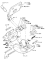
次に、図1を用いて、ウィンドウロック装置50の構成を説明する。図1は本実施の形態例のウィンドウロック装置の分解斜視図である。
図において、300はウィンドウガラス100の回転端部側にクッション301を介して取り付けられる第1のブラケットである。この第1のブラケット300には、ウィンドウガラス100の回転軸と平行な貫通穴302が形成された立壁部303が形成されている。
【0018】
500は第1のブラケット300の立壁部303が係合可能な断面形状が略コ字形のレバーで、一方の端部側には、第1のブラケット300の貫通穴302に対向する貫通穴501,501′が形成されている。そして、レバー500の貫通穴501,501′と、第1のブラケット300の貫通穴302とに嵌合するピン400を用いて、レバー500は第1のブラケット300に対して回転可能に取り付けられている。
【0019】
リンク700の一方の端部側と、他方の端部側とには、貫通穴701,702とが設けられている。
レバー500の回転端部側には、リンク700の一方の端部側に形成された貫通穴701に対向する貫通穴502,502′が形成されている。そして、レバー500の貫通穴502,502′とリンク700の貫通穴701とに嵌合するピン401を用いて、レバー500の回転端部側に、リンク700の一方の端部側が回転可能に取り付けられている。
【0020】
900は、基端部側がリアクォータウィンドウ200の開口縁部であるボデー201に取り付けられる第2のブラケットである。この第2のブラケット900の先端部側は曲げ加工され、リンク700の他方の回転端部側に形成された貫通穴702に対向する穴901が形成されている。そして、第2のブラケット900の穴901とリンク700の貫通穴702とに嵌合するピン403を用いて、第2のブラケット900には、リンク700の他方の回転端部側が回転可能に取り付けられている。
【0021】
又、第2のブラケット900には、弾性材でなるクッション903が設けられている。
次に、リンク700とレバー500との間の回転を禁止するロック機構1000の説明を行なう。
【0022】
レバー500には、レバーの回転軸であるピン401と略直交する方向に設けられたシャフト部509が形成されている。このシャフト部509に、ロック部材1100の貫通穴1101が嵌合し、ロック部材1100はシャフト部509に対して回転可能となっている。ロック部材1100には、貫通穴1101を介して対称な位置に、シャフト部509方向の突起1102,1103が形成されている。更に、ロック部材1100の周面には、リンク700方向へ突出するロック突起1105が形成されている。
【0023】
一方、リンク700には、貫通穴701の軸(レバー500との回転軸)を中心とし、ロック部材1100のロック突起1105が係合する円周方向のガイド溝720が形成されている。更に、リンク700には、ガイド溝720に連設され、貫通穴701の軸(レバー500との回転軸)方向に延び、ウィンドウガラス100が閉じている状態で、ロック部材1100のロック突起1105が係合可能なロック溝730が形成されている。
【0024】
レバー500には、略矩形の穴510,510′が形成され、これらの穴510,510′には、ロック解除部材としてのボタン1200,1200′が移動可能に係合している。これらボタン1200,1200′の先端部には、ロック部材1100の突起1102,1103が係合する長穴1201,1201′が形成されている。従って、ボタン1200,1200′を互いに接近する方向に移動させると、ロック部材1100はシャフト部509を中心に図1において矢印III方向に回転し、逆に、ボタン1200,1200′を互に離反する方向に移動させると、ロック部材1100はシャフト部509を中心に反矢印III方向に回転するようになっている。
【0025】
1300は一方の端部がボタン1200に、他方の端部がボタン1200′に係止され、これらボタン1200,1200′を互に離れる方向に付勢する付勢部材としてのスプリングである。
【0026】
このスプリング1300の付勢力により、ロック部材1100は反矢印III方向に付勢されている。
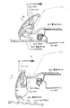
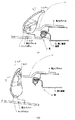
次に、上記構成の動作を図2及び図3を用いて説明する。図2はウィンドウロック装置の動作を説明する構成図で、(a)図はウィンドウガラスが閉状態、(b)図はウィンドウガラスが開状態を示している。図3は図1に示すロック機構の動作を説明する図で、(a)図はロック状態、(b)図はロック解除状態を示している。尚、図2においては、ロック機構1000は省略している。
【0027】
閉状態にあるウィンドウガラス100を開くには、先ずロック機構1000を操作する。即ち、図3(a)に示すように、ウィンドウガラス100が閉状態にある時は、ロック部材1100のロック突起1105がリンク700のロック溝730に係合し、リンク700とレバー500との間の回転を禁止している。
【0028】
ここで、ボタン1200,1200′をスプリング1300の付勢力に抗してそれぞれ押すと、ロック部材1100が回転し、ロック突起1105がリンク700のガイド溝720へ移動し、リンク700とレバー500との間の回転が可能となる。
【0029】
ボタン1200,1200′への操作力を保持したまま、レバー500を図2(a)において、矢印IV方向に若干引くと、リンク700が回転し、ロック溝730はロック部材1100のロック突起1105より離れるので、ボタン1200,1200′への操作力を解除してもロック部材1100のロック突起1105はロック溝730に係合せず、リンク700とレバー500との間の回転は可能となる。
【0030】
更に、レバー500を図2において、矢印IV方向に引き続けると、ウィンドウロック装置のロックが解除され、その後、レバー500を車外へ押すことによりウィンドウガラス100の回転端部側が車外へ開いた図2(b)に示す状態となる。
【0031】
又、ウィンドウガラス100を閉じる場合には、図2(b)の状態からレバー500を矢印V方向へ引き、ウィンドウガラス100を閉じ、更に、レバー500を反矢印V方向に押すことにより、図2(a)に示すロック状態に戻る。この時、リンク700のロック溝730がロック部材1100のロック突起1105と係合可能な位置までリンク700が戻っているので、スプリング1300によりロック溝730に係合する方向に付勢されているロック部材1100のロック突起1105はリンク700のロック溝730に係合し、再び、リンク700とレバー500との間の回転が禁止される。
【0032】
上記構成によれば、ウィンドウガラス100の閉状態で、車外から針金等でレバー500を押しても、ロック機構1000によりリンク700とレバー500との間の回転が禁止されているので、車外からロック解除されにくく、盗難を防止することができる。
【0033】
更に、本実施の形態例では、ボタン1200,1200′を操作したまま、レバー500を操作しなければ、ウィンドウガラス100を開くことができないので、一層、車外よりからロック解除されにくく、盗難を防止することができる。
【0034】
尚、本発明は上記実施の形態例に限定するものではない。例えば、図5に示すような構成でもよい。図5において、図1と同一部部分には、同一符号を付し、それらの説明は省略する。
【0035】
本実施の形態例と前述の形態例との相違点は、リンク700とレバー500との間の回転が禁止するロック機構である。本実施の形態例のロック機構2000は、レバー500にシャフト2100を設け、更に、レバー500にシャフト2100に対向する略矩形の穴550を設けている。
【0036】
2200はレバー500の穴550に移動可能に係合するボタンである。このボタン2200には、大径部2201と、シャフト2100が嵌合する小径部2202とからなる段付き穴2203が形成されている。
【0037】
更に、ボタン2200には、リンク700のガイド溝720及びロック溝730に係合可能なロック突起2205が形成されている。
シャフト2100を巻装するように設けられたスプリング2300の一方の端部はレバー500に、他方の端部はボタン2200の段付き穴2203の大径部2201と小径部2202との段部に係止されている。従って、このスプリング2300は、ボタン2200をレバー500より突出させる方向、即ち、ウィンドウガラス100が閉状態の時、ロック突起2205がリンク700のロック溝730に係合する方向へ付勢してる。
【0038】
上記構成のロック機構2000の動作を説明すると、ウィンドウガラス100が閉状態にある時は、ボタン2200のロック突起2205がリンク700のロック溝730に係合し、リンク700とレバー500との間の回転を禁止している。
【0039】
ここで、ボタン2200をスプリング2300の付勢力に抗して押すと、ボタン2200のロック突起2205がリンク700のガイド溝720へ移動し、リンク700とレバー500との間の回転が可能となる。
【0040】
更に、上記実施の形態例では、ロック機構1000,2000はリンク700とレバー500との間の回転を禁止するものであったが、これに限定するものではない。リンク700とレバー500との間の回転、レバー500の第1のブラケット300に対する回転、リンク700の第2のブラケット900に対する回転のうち、少なくとも1つの回転を禁止するようにすれば良い。
【0041】
【発明の効果】
以上述べたように請求項1記載の発明によれば、ロック機構を前記レバーに設けられ、前記リンクの回転軸と略直交する軸を中心に回転可能に設けられたロック部材と、前記リンクに設けられ、前記ロック部材が係合し、前記レバーとの回転軸を中心とする円周方向のガイド溝と、前記ガイド溝に連設され、前記リンクの回転軸方向に延出し、前記ウィンドウガラスが閉状態で前記ロック部材が係合可能なロック溝と、前記レバーに設けられ、前記ロック部材を前記ロック溝方向に付勢する付勢部材と、前記レバーに設けられ、前記ロック部材を前記付勢手段の付勢力に抗して回転させるロック解除手段とから構成したことにより、ウィンドウガラス閉状態で、車外から針金等でレバーを押しても、ロック機構によりリンクとレバーとの間の回転が禁止されているので、車外よりからロック解除されにくく、盗難を防止することができる。
【0043】
更に、ロック解除手段を操作したまま、レバーを操作しなければ、ウィンドウガラスを開くことができないので、一層、車外よりからロック解除されにくく、盗難を防止することができる。
【図面の簡単な説明】
【図1】本発明の一実施の形態例のウィンドウロック装置の分解斜視図である。
【図2】ウィンドウロック装置の動作を説明する構成図で、(a)図はウィンドウガラスが閉状態、(b)図はウィンドウガラスが開状態を示す図である。
【図3】図1に示すロック機構の動作を説明する図で、(a)図はロック状態、(b)図はロック解除状態を示す図である
【図4】図1に示すウィンドウロック装置が設けられた車両の全体を説明する図である。
【図5】他の実施の形態例を説明する分解斜視図である。
【図6】従来のウィンドウロック装置の一例を示す構成図である。
【符号の説明】
300 第1のブラケット
500 レバー
700 リンク
900 第2のブラケット
1000 ロック機構[0001]
BACKGROUND OF THE INVENTION
The present invention includes a first bracket attached to a rotating end side of a window glass, the base end side of which is rotatably provided at an opening edge of the window, and a base end side of the first bracket which is rotatably provided. A second lever attached to an opening edge of the window, a link provided on one end side of the lever so as to be rotatable, and a link provided on the other end side of the link. The present invention relates to a window lock device including a bracket.
[0002]
[Prior art]
A quarter window glass of an automobile is provided so as to be openable and closable, and further, a window lock device for prohibiting movement of the quarter window in the closed state in the opening direction is provided.
[0003]
6A and 6B are configuration diagrams showing an example of the window lock device, in which FIG. 6A is a view showing when the window glass is in a closed state, and FIG. 6B is a view showing when the window glass is in an open state. .
[0004]
In the figure, a first bracket 3 is attached to a rotating end portion side of a window glass 1 in which a base end portion is rotatably provided at an opening edge portion of a
[0005]
One end side of the link 7 is rotatably attached to the rotation end side of the lever 5.
On the other hand, a second bracket 9 is attached to the opening edge (body) 10 of the
[0006]
Next, the operation of the above configuration will be described. (a) The state shown to a figure has shown the time of the window glass 1 being a closed state. Here, when the lever 5 is pulled in the direction of arrow I, the lock is released, and then the lever 5 is pushed out of the vehicle to open the rotating end of the window glass 1 to the outside of the vehicle (b).
[0007]
When closing the window glass 1, (b) pulling the lever 5 in the direction of arrow II from the state shown in the figure, closing the window glass 1, and further pushing the lever 5 in the opposite arrow II direction, (a) Return to the locked state shown in the figure.
[0008]
[Problems to be solved by the invention]
However, when the locking device having the above configuration is in the locked state shown in FIG. 6A, the lever 5 is pushed in the direction of arrow I from outside the vehicle using a wire or the like through the gap S between the window glass 1 and the opening edge 10. Thus, there is a problem that the lever 5 can be rotated in the direction of arrow I and the window glass 1 can be easily opened.
[0009]
Therefore, there is a problem that articles and vehicles in the vehicle are stolen.
The present invention has been made in view of the above problems, and an object of the present invention is to provide a window lock device that is difficult to unlock from the outside of the vehicle and can prevent theft.
[0010]
[Means for Solving the Problems]
The invention according to claim 1, which solves the above-mentioned problem, includes a first bracket attached to a rotating end side of a window glass, a base end side of which is rotatably provided at an opening edge of the window, and the first bracket. A lever whose base end side is rotatably provided, a link whose one end side is rotatably provided on the rotation end side of the lever, and the other end side of the link is rotatably provided. A window locking device comprising a second bracket attached to an opening edge , wherein the locking member is provided on the lever and is rotatable about an axis substantially orthogonal to the rotation axis of the link; A guide groove provided in a link, engaged with the lock member, and provided in a circumferential guide groove centered on a rotation axis of the lever and the guide groove; and extending in a rotation axis direction of the link; A lock groove that can be engaged with the lock member when a lath is closed, a biasing member that is provided in the lever and biases the lock member in the direction of the lock groove, and is provided in the lever. A window lock device comprising a lock mechanism comprising: a lock release unit that rotates against a biasing force of the biasing unit .
[0013]
When the window glass is in the closed state, the lock member urged by the urging means engages with the lock groove, thereby prohibiting the rotation of the link.
When the lock release means is operated against the urging force of the urging means, the engagement between the lock member and the lock groove is released, and the lock member moves to the guide groove, allowing rotation between the link and the lever. It becomes.
[0014]
Here, the window glass can be opened by operating the lever while operating the unlocking means.
According to such a configuration, even when the lever is pushed with a wire or the like from the outside of the vehicle with the window glass closed, the lock mechanism prohibits rotation between the link and the lever, so it is difficult to unlock from outside the vehicle, Theft can be prevented.
[0015]
Furthermore, since the window glass cannot be opened unless the lever is operated while the lock release means is operated, the lock can be prevented from being released from outside the vehicle, and theft can be prevented.
[0016]
DETAILED DESCRIPTION OF THE INVENTION
Next, an embodiment of the present invention will be described with reference to FIGS.
The window lock device of this embodiment locks the window glass 100 of the rear quarter window 200 of the vehicle as shown in FIG. The window glass 100 is rotatably attached to the vehicle body side using a hinge 101 on the base end side, and the window lock device 50 is provided on the rotation end side of the window glass 100.
[0017]
Next, the configuration of the window lock device 50 will be described with reference to FIG. FIG. 1 is an exploded perspective view of a window lock device according to the present embodiment.
In the figure,
[0018]
Reference numeral 500 denotes a lever having a substantially U-shaped cross-section that can be engaged with the standing wall 303 of the
[0019]
Through
On the rotation end side of the lever 500, through
[0020]
Reference numeral 900 denotes a second bracket that is attached to a body 201 whose base end side is an opening edge of the rear quarter window 200. The tip end side of the second bracket 900 is bent to form a
[0021]
The second bracket 900 is provided with a cushion 903 made of an elastic material.
Next, the lock mechanism 1000 that prohibits rotation between the link 700 and the lever 500 will be described.
[0022]
The lever 500 is formed with a shaft portion 509 provided in a direction substantially orthogonal to the
[0023]
On the other hand, the link 700 is formed with a guide groove 720 in the circumferential direction around the axis of the through hole 701 (rotational axis with the lever 500) and with which the lock protrusion 1105 of the lock member 1100 engages. Further, the link 700 is connected to the guide groove 720, extends in the direction of the axis of the through hole 701 (rotation axis with the lever 500), and the lock projection 1105 of the lock member 1100 is in a state where the window glass 100 is closed. An engageable lock groove 730 is formed.
[0024]
The lever 500 is formed with substantially
[0025]
Reference numeral 1300 denotes a spring as an urging member that has one end locked to the
[0026]
Due to the urging force of the spring 1300, the lock member 1100 is urged in the direction opposite to the arrow III.
Next, the operation of the above configuration will be described with reference to FIGS. 2A and 2B are configuration diagrams for explaining the operation of the window lock device. FIG. 2A shows a closed state of the window glass, and FIG. 2B shows an opened state of the window glass. 3A and 3B are diagrams for explaining the operation of the locking mechanism shown in FIG. 1, wherein FIG. 3A shows a locked state, and FIG. 3B shows a unlocked state. In FIG. 2, the lock mechanism 1000 is omitted.
[0027]
In order to open the window glass 100 in the closed state, first, the lock mechanism 1000 is operated. That is, as shown in FIG. 3A, when the window glass 100 is in the closed state, the lock protrusion 1105 of the lock member 1100 engages with the lock groove 730 of the link 700, and the link 700 and the lever 500 are Rotation is prohibited.
[0028]
Here, when the
[0029]
When the lever 500 is pulled slightly in the direction of arrow IV in FIG. 2A while maintaining the operation force to the
[0030]
Further, when the lever 500 is continuously pulled in the direction of arrow IV in FIG. 2, the lock of the window lock device is released, and then the lever 500 is pushed out of the vehicle to open the rotating end side of the window glass 100 to the outside of the vehicle. The state shown in (b) is obtained.
[0031]
When the window glass 100 is closed, the lever 500 is pulled in the direction of arrow V from the state of FIG. 2B, the window glass 100 is closed, and further, the lever 500 is pushed in the opposite arrow V direction, so that FIG. Return to the locked state shown in (a). At this time, since the link 700 has returned to a position where the lock groove 730 of the link 700 can be engaged with the lock protrusion 1105 of the lock member 1100, the lock urged in the direction of engaging with the lock groove 730 by the spring 1300. The lock protrusion 1105 of the member 1100 engages with the lock groove 730 of the link 700, and the rotation between the link 700 and the lever 500 is prohibited again.
[0032]
According to the above configuration, even when the lever 500 is pushed with a wire or the like from outside the vehicle in the closed state of the window glass 100, the lock mechanism 1000 prohibits the rotation between the link 700 and the lever 500. It is difficult to be stolen and theft can be prevented.
[0033]
Furthermore, in the present embodiment, the window glass 100 cannot be opened unless the lever 500 is operated while the
[0034]
The present invention is not limited to the above embodiment. For example, a configuration as shown in FIG. 5, the same parts as those in FIG. 1 are denoted by the same reference numerals, and description thereof will be omitted.
[0035]
The difference between the present embodiment and the above-described embodiment is a lock mechanism that prohibits rotation between the link 700 and the lever 500. In the
[0036]
Reference numeral 2200 denotes a button movably engaged with the hole 550 of the lever 500. The button 2200 has a stepped
[0037]
Further, the button 2200 is formed with a lock protrusion 2205 that can be engaged with the guide groove 720 and the lock groove 730 of the link 700.
One end of a spring 2300 provided so as to wind the shaft 2100 is engaged with the lever 500, and the other end is engaged with a step between the
[0038]
The operation of the
[0039]
Here, when the button 2200 is pushed against the urging force of the spring 2300, the lock protrusion 2205 of the button 2200 moves to the guide groove 720 of the link 700, and rotation between the link 700 and the lever 500 becomes possible.
[0040]
Further, in the above embodiment, the
[0041]
【The invention's effect】
As described above, according to the first aspect of the present invention, the lock mechanism is provided on the lever, the lock member is provided to be rotatable about an axis substantially orthogonal to the rotation axis of the link, and the link is provided on the link. A guide groove in a circumferential direction centered on a rotation axis with the lever, and connected to the guide groove, extending in the direction of the rotation axis of the link, A lock groove that can be engaged with the lock member in a closed state, a biasing member that is provided in the lever and biases the lock member in the lock groove direction, and is provided in the lever. Since the lock release means is configured to rotate against the urging force of the urging means, even if the lever is pushed with a wire etc. from the outside of the vehicle in the closed state of the window glass, the lock mechanism between the link and the lever Since the rotation is prohibited, less likely to be unlocked from the from the outside of the vehicle, it is possible to prevent the theft.
[0043]
Furthermore, since the window glass cannot be opened unless the lever is operated while the lock release means is operated, the lock can be prevented from being released from outside the vehicle, and theft can be prevented.
[Brief description of the drawings]
FIG. 1 is an exploded perspective view of a window lock device according to an embodiment of the present invention.
FIGS. 2A and 2B are configuration diagrams for explaining the operation of the window lock device, in which FIG. 2A is a diagram showing a closed state of the window glass, and FIG. 2B is a diagram showing an opened state of the window glass;
3 is a diagram for explaining the operation of the lock mechanism shown in FIG. 1, wherein FIG. 4 (a) shows a locked state, and FIG. 4 (b) shows a unlocked state. FIG. 4 shows the window lock device shown in FIG. It is a figure explaining the whole vehicle provided with.
FIG. 5 is an exploded perspective view for explaining another embodiment.
FIG. 6 is a block diagram showing an example of a conventional window lock device.
[Explanation of symbols]
300 First bracket 500 Lever 700 Link 900 Second bracket 1000 Lock mechanism
Claims (1)
前記レバーに設けられ、前記リンクの回転軸と略直交する軸を中心に回転可能に設けられたロック部材と、
前記リンクに設けられ、前記ロック部材が係合し、前記レバーとの回転軸を中心とする円周方向のガイド溝と前記ガイド溝に連設され、前記リンクの回転軸方向に延出し、前記ウィンドウガラスが閉状態で前記ロック部材が係合可能なロック溝と、
前記レバーに設けられ、前記ロック部材を前記ロック溝方向に付勢する付勢部材と、
前記レバーに設けられ、前記ロック部材を前記付勢手段の付勢力に抗して回転させるロック解除手段と、
からなるロック機構を設けたことを特徴とするウィンドウロック装置。A first bracket attached to the rotating end side of the window glass, the base end side of which is provided rotatably at the opening edge of the window, and a lever provided on the first bracket so that the base end side of the window glass is rotatable; The lever includes a link that is rotatably provided at one end side on the rotating end side of the lever, and a second bracket that is rotatably provided at the other end side of the link and is attached to the opening edge of the window. A window locking device,
A locking member provided on the lever and rotatably provided around an axis substantially orthogonal to the rotation axis of the link;
Provided in the link, the lock member engages, and is provided in a circumferential guide groove centered on the rotation axis of the lever and the guide groove, extends in the rotation axis direction of the link, A lock groove with which the lock member can be engaged when the window glass is closed;
An urging member provided on the lever and urging the lock member in the lock groove direction;
A lock releasing means provided on the lever and rotating the lock member against a biasing force of the biasing means;
A window lock device comprising a lock mechanism comprising:
Priority Applications (1)
| Application Number | Priority Date | Filing Date | Title |
|---|---|---|---|
| JP00221198A JP3795656B2 (en) | 1998-01-08 | 1998-01-08 | Window lock device |
Applications Claiming Priority (1)
| Application Number | Priority Date | Filing Date | Title |
|---|---|---|---|
| JP00221198A JP3795656B2 (en) | 1998-01-08 | 1998-01-08 | Window lock device |
Publications (2)
| Publication Number | Publication Date |
|---|---|
| JPH11192837A JPH11192837A (en) | 1999-07-21 |
| JP3795656B2 true JP3795656B2 (en) | 2006-07-12 |
Family
ID=11523025
Family Applications (1)
| Application Number | Title | Priority Date | Filing Date |
|---|---|---|---|
| JP00221198A Expired - Fee Related JP3795656B2 (en) | 1998-01-08 | 1998-01-08 | Window lock device |
Country Status (1)
| Country | Link |
|---|---|
| JP (1) | JP3795656B2 (en) |
Families Citing this family (4)
| Publication number | Priority date | Publication date | Assignee | Title |
|---|---|---|---|---|
| KR20020083801A (en) * | 2001-04-30 | 2002-11-04 | 현대자동차주식회사 | Swivel glass opening and closing structure for an omnibus |
| EP1277903A1 (en) | 2001-07-19 | 2003-01-22 | Società Italiana Vetro - SIV S.p.A. | A catch device for a pivoting window |
| KR100448341B1 (en) * | 2002-05-13 | 2004-09-10 | 기아자동차주식회사 | vehicles's window glass a quarter of lock |
| CN110284787A (en) * | 2019-07-09 | 2019-09-27 | 象山天星汽配有限责任公司 | A kind of adjustable automobiles window button |
-
1998
- 1998-01-08 JP JP00221198A patent/JP3795656B2/en not_active Expired - Fee Related
Also Published As
| Publication number | Publication date |
|---|---|
| JPH11192837A (en) | 1999-07-21 |
Similar Documents
| Publication | Publication Date | Title |
|---|---|---|
| US5630630A (en) | Glove compartment latch mechanism | |
| JP2553315Y2 (en) | Lid lock device | |
| US4194377A (en) | Locking means for automobile doors | |
| US5984384A (en) | Vehicle door latch device with self-cancelling mechanism | |
| JPH0223670B2 (en) | ||
| JP3795656B2 (en) | Window lock device | |
| KR100767969B1 (en) | The Latch Structure Which Is Established In The Trunk or Tail Gate | |
| JP2776148B2 (en) | Glove box locking device | |
| JP2565196Y2 (en) | Lock device for glove box | |
| JP4559603B2 (en) | Car trunk lid lock device | |
| JP3134579B2 (en) | Car door lock knob structure | |
| JP4137705B2 (en) | Car trunk lock equipment | |
| GB2257467A (en) | Antitheft type door lock system. | |
| JPH11141207A (en) | Latch lock | |
| JP3909427B2 (en) | Door lock device for automobile | |
| KR100431985B1 (en) | Door locker of a driver's seat for vehicles | |
| JP4335552B2 (en) | Locking device | |
| JPH0320460Y2 (en) | ||
| JP4098000B2 (en) | Vehicle locking device | |
| JPS5823883Y2 (en) | Lid simple key lock device | |
| JP2586118Y2 (en) | Lid lock device | |
| JP3364604B2 (en) | Opening and closing door handle device | |
| JP2558530B2 (en) | Vehicle door lock device | |
| JPH035661Y2 (en) | ||
| KR20220031419A (en) | Door opening prevention structure in vehicle collision |
Legal Events
| Date | Code | Title | Description |
|---|---|---|---|
| A131 | Notification of reasons for refusal |
Free format text: JAPANESE INTERMEDIATE CODE: A131 Effective date: 20050118 |
|
| A521 | Written amendment |
Free format text: JAPANESE INTERMEDIATE CODE: A523 Effective date: 20050315 |
|
| TRDD | Decision of grant or rejection written | ||
| A01 | Written decision to grant a patent or to grant a registration (utility model) |
Free format text: JAPANESE INTERMEDIATE CODE: A01 Effective date: 20060411 |
|
| A61 | First payment of annual fees (during grant procedure) |
Free format text: JAPANESE INTERMEDIATE CODE: A61 Effective date: 20060413 |
|
| R150 | Certificate of patent or registration of utility model |
Free format text: JAPANESE INTERMEDIATE CODE: R150 |
|
| FPAY | Renewal fee payment (event date is renewal date of database) |
Free format text: PAYMENT UNTIL: 20090421 Year of fee payment: 3 |
|
| FPAY | Renewal fee payment (event date is renewal date of database) |
Free format text: PAYMENT UNTIL: 20100421 Year of fee payment: 4 |
|
| FPAY | Renewal fee payment (event date is renewal date of database) |
Free format text: PAYMENT UNTIL: 20110421 Year of fee payment: 5 |
|
| FPAY | Renewal fee payment (event date is renewal date of database) |
Free format text: PAYMENT UNTIL: 20110421 Year of fee payment: 5 |
|
| FPAY | Renewal fee payment (event date is renewal date of database) |
Free format text: PAYMENT UNTIL: 20120421 Year of fee payment: 6 |
|
| FPAY | Renewal fee payment (event date is renewal date of database) |
Free format text: PAYMENT UNTIL: 20120421 Year of fee payment: 6 |
|
| FPAY | Renewal fee payment (event date is renewal date of database) |
Free format text: PAYMENT UNTIL: 20130421 Year of fee payment: 7 |
|
| FPAY | Renewal fee payment (event date is renewal date of database) |
Free format text: PAYMENT UNTIL: 20140421 Year of fee payment: 8 |
|
| LAPS | Cancellation because of no payment of annual fees |