JP3792034B2 - Particle analyzer - Google Patents
Particle analyzer Download PDFInfo
- Publication number
- JP3792034B2 JP3792034B2 JP35387297A JP35387297A JP3792034B2 JP 3792034 B2 JP3792034 B2 JP 3792034B2 JP 35387297 A JP35387297 A JP 35387297A JP 35387297 A JP35387297 A JP 35387297A JP 3792034 B2 JP3792034 B2 JP 3792034B2
- Authority
- JP
- Japan
- Prior art keywords
- chamber
- pump
- sample
- wall
- particle analyzer
- Prior art date
- Legal status (The legal status is an assumption and is not a legal conclusion. Google has not performed a legal analysis and makes no representation as to the accuracy of the status listed.)
- Expired - Fee Related
Links
- 239000002245 particle Substances 0.000 title claims description 35
- 239000012530 fluid Substances 0.000 claims description 26
- 239000012528 membrane Substances 0.000 claims description 16
- 238000004891 communication Methods 0.000 claims description 4
- 238000001514 detection method Methods 0.000 description 35
- 210000004369 blood Anatomy 0.000 description 25
- 239000008280 blood Substances 0.000 description 25
- 239000003085 diluting agent Substances 0.000 description 16
- 210000000601 blood cell Anatomy 0.000 description 15
- 210000000265 leukocyte Anatomy 0.000 description 15
- 238000000034 method Methods 0.000 description 14
- 210000003743 erythrocyte Anatomy 0.000 description 13
- 238000011002 quantification Methods 0.000 description 9
- 238000010790 dilution Methods 0.000 description 8
- 239000012895 dilution Substances 0.000 description 8
- 238000005259 measurement Methods 0.000 description 8
- 239000003219 hemolytic agent Substances 0.000 description 7
- 239000007788 liquid Substances 0.000 description 5
- QSHDDOUJBYECFT-UHFFFAOYSA-N mercury Chemical compound [Hg] QSHDDOUJBYECFT-UHFFFAOYSA-N 0.000 description 3
- 229910052753 mercury Inorganic materials 0.000 description 3
- 210000001772 blood platelet Anatomy 0.000 description 2
- 238000011109 contamination Methods 0.000 description 2
- 238000007865 diluting Methods 0.000 description 2
- 238000006073 displacement reaction Methods 0.000 description 2
- 238000000684 flow cytometry Methods 0.000 description 2
- 230000002093 peripheral effect Effects 0.000 description 2
- 238000002360 preparation method Methods 0.000 description 2
- 210000002700 urine Anatomy 0.000 description 2
- 229920002943 EPDM rubber Polymers 0.000 description 1
- BZHJMEDXRYGGRV-UHFFFAOYSA-N Vinyl chloride Chemical compound ClC=C BZHJMEDXRYGGRV-UHFFFAOYSA-N 0.000 description 1
- 238000013019 agitation Methods 0.000 description 1
- 230000007423 decrease Effects 0.000 description 1
- 238000010586 diagram Methods 0.000 description 1
- 238000007599 discharging Methods 0.000 description 1
- 230000000694 effects Effects 0.000 description 1
- 229920001971 elastomer Polymers 0.000 description 1
- 230000007257 malfunction Effects 0.000 description 1
- 239000000463 material Substances 0.000 description 1
- 238000000691 measurement method Methods 0.000 description 1
- 238000002156 mixing Methods 0.000 description 1
- 230000002572 peristaltic effect Effects 0.000 description 1
- 239000002574 poison Substances 0.000 description 1
- 231100000614 poison Toxicity 0.000 description 1
- 239000011148 porous material Substances 0.000 description 1
- 238000012545 processing Methods 0.000 description 1
- 238000005070 sampling Methods 0.000 description 1
- 239000000243 solution Substances 0.000 description 1
- 239000000126 substance Substances 0.000 description 1
- 229920003002 synthetic resin Polymers 0.000 description 1
- 239000000057 synthetic resin Substances 0.000 description 1
- 238000005406 washing Methods 0.000 description 1
- 238000003466 welding Methods 0.000 description 1
Images


Description
【0001】
【発明の属する技術分野】
この発明は粒子分析装置に関し、さらに詳しくは、尿、血液等の試料に含まれる血球等の粒子数を測定する粒子分析装置に関する。
【0002】
【従来の技術】
血球等の粒子を測定する方法として、フローサイトメトリー法、電気抵抗法が周知である。例えば、電気抵抗法では、検出器、すなわち電流を流した微細孔(オリフィスとしての機能を有する整流素子)に微量定量された血液試料を供給し、この微細孔を通過する際に発生する電気信号変化を検出して血球等の粒子数、粒度分布を得る。
このような測定法は、検出器に流す試料流体の流速を安定させ、その量が正確に定量されていなければ粒子数を正確に測定することができない。
【0003】
検出器に流す試料流体の量を定量するためには、
(i) 検出器に流す試料流体の液量を定量検知する検知部を流路に設ける定量方法であり、定量検知部として、水銀U字管や球を利用したマノメータ(実公昭62−22830号公報参照)が知られている。
(ii)試料流体を測定する時間を一定時間に設定する、すなわち測定時間を基準とした定量方法。
(iii) シリンジあるいは、しごきポンプ(ペリスタルラックポンプ)の定量供給手段で試料を加圧または吸引して検出器に流す試料流体の量を所定の量とする方法等が挙げられる。
【0004】
【発明が解決しようとする課題】
しかし、前記(i) の手法では、流路に検知部を設けねばならず、血液試料等では汚れが生じやすく検知不良が起こりうる。水銀U字管は毒物である水銀を使用するので、取扱いが面倒であり、球を利用したマノメータは構造が複雑で球自体の動作不良が起こるという問題がある。
前記(ii)の手法では、流量を正確に一定にする必要がある。試料の液温が変われば、流量が変わるし、検出部に汚れが付着して微細孔が小さくなると、流量が少なくなり、定量精度が確保できないという問題がある。
前記(iii) の手法では、シリンジやしごきポンプを所定の量の試料流体を安定した流速にて流すためのステッピングモータ等の駆動部及び制御部を備えねばならず複雑で高価となり、又、パッキンやチューブを定期的に交換せねばならないという問題がある。
【0005】
この発明は、このような事情を考慮してなされたもので、正確に定量された量の試料流体を安定した流速で検出器に供給することができ、構成が簡単な粒子分析装置を提供するものである。
【0006】
【課題を解決するための手段】
本発明は、定量された試料流体中の粒子数を測定する粒子分析装置において、一定量の試料流体を検出器に流すための定量供給手段として、膜体と、この膜体で仕切られる室とからなり、各室の内壁には流通口部が形成され、一方の室の流通口部が圧力源と連通され、他方の室の流通口部が検出器と連通されてなるポンプを備え、さらにこのポンプは、圧力源の切換えにより、膜体を一方の室の内壁に密着した状態から他方の室の内壁に密着した状態へと作動させ、両方の室の内容積量に対応する試料流体を検出器に流して試料流体中の粒子数を測定するよう構成されたことを特徴とする粒子分析装置を提供する。
【0007】
この発明におけるポンプとは、空気源や液体ポンプ等に広く用いられるもので膜体の作動により流体を吸引、吐出するダイアフラム式ポンプを意味し、具体的には膜体と、この膜体が両側に作動できるように支持する支持部と、膜体を作動させる圧力源とからなる。
【0008】
このようなポンプにより吸引排出される量は、膜の大きさや膜が作動できる大きさによって決められる。この量は充分な定量性を満たすものではないが、ある程度規定できるので、試料等を吸引排出する簡易手段として分析装置においてもいろいろと用いられている。例えば、吸引排出による試料攪拌(特開平5−40123号公報参照)、試料の充填(特開平5−232011号公報参照)、複数試料の混和、洗浄等がある。
【0009】
この発明では、試料を吸引・排出する量を陰圧もしくは陽圧によって膜体が片側に室に密着状態から圧を切り換え、膜体が逆側の室に密着されるまでとすることによって、両室の内容積の量を規定することができる。
膜体が密着することができる室を設けることによって正確に定量できるポンプを定量供給手段として用いるため前記手法における複雑な機構も必要とせず、検知部の汚れという問題もない簡易な構成である。
【0010】
この発明における試料流体中の粒子とは、例えば、所定の希釈倍率に希釈された血液中の赤血球、血小板及び白血球、尿中の懸濁物質が挙げられる。
この発明における検出器には、例えば、血液試料中の血球を分析対象の粒子として、その粒子数、粒度分布を得るフローサイトメトリー法、電気抵抗法が挙げられる。
【0011】
【発明の実施の形態】
図1〜6は、本発明の一つの実施形態による粒子分析装置としての血球分析装置10を示す。
図1により血球分析装置10の全体構成をその流体経路構成に基づいて説明する。なお、この血球分析装置10は、図1に示され、後述するように、血液試料を試料流体として扱い、赤血球及び血小板を赤血球検出系で、白血球を白血球検出系でそれぞれ検出するよう構成されている。血液中の血球の個数は大きく異なるため(通常赤血球400万/μl程度に対して白血球5000/μl程度)、赤血球検出系に供給される血液試料と白血球検出系に供給される血液試料は、希釈倍率が異なるとともに処理が異なる。以下の実施形態では、略同一構成の2つの検出系を備えているが、赤血球検出系では希釈液で25000倍に希釈された血液試料2mlが供給され、そのうちの250μlが測定に供される。また、白血球検出系では希釈液と溶血剤とで500倍に希釈溶血処理された血液試料3mlが供給され、そのうちの500μlが測定に供される。
【0012】
血球分析装置10は、定量供給手段としてのポンプ11、12及び陰・陽圧手段である陰圧チャンバ13、陽圧チャンバ14と、検出器としての検出チャンバ31、32と、試料希釈部5とから構成される。上記したように、ポンプ11及び検出チャンバ31は赤血球検出系に、ポンプ12及び検出チャンバ32は白血球検出系に、それぞれ供される。
【0013】
試料定量希釈部5は、試料採取用ピペット51と、希釈液供給チャンバ52と、試料容器S等から試料採取用ピペット51で採取した血液試料を希釈液供給チャンバ52から供給される希釈液で所定の希釈倍率に希釈する周知のサンプリングバルブを備えた試料定量機構56とから主に構成される。試料定量機構56からは、2種類の異なる希釈倍率で希釈された血液試料を供給するための管路54、55が延出する。
【0014】
管路54の他端には、試料定量希釈部5により希釈された血液試料を受け入れる赤血球検出用検出チャンバ31が配設され、管路55の他端には、試料定量希釈部5により希釈された血液試料を受け入れる白血球検出用検出チャンバ32が配設される。白血球検出用検出チャンバ32には、溶血剤を供給する溶血剤供給部4に接続され延出した管路41の他端が、検出チャンバ32内に溶血剤を供給可能に接続されている。
各検出チャンバ31、32には、検出器33、34がそれぞれ備えられている。検出器33、34は、周知の電気抵抗法により粒子としての血球についてその粒度分布、粒子数を検出するオリフィスであって、一対の電極間に電圧を印加して検出器33、34を血球が通過する際に発生するインピーダンス変化に基づく信号を分析する機能を有する。
【0015】
ポンプ11、12の片方の室21,27は検出チャンバ31、32に接続されている。
ポンプ11、12の上記とは逆側の室22、28には、バルブV7の切り換えにより陰圧及び陽圧を印加することができる陰圧チャンバ13及び陽圧チャンバ14が接続されている。
陰圧チャンバ13には、陰圧チャンバ13を前記した検出チャンバ31、32の排液チャンバとして機能させるべくバルブV3〜V6をそれぞれ介接した管路が接続されている。
【0016】
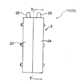
図2〜5は、本発明の一つの実施形態によるポンプ11(12は同一構成のため説明を省略する)を示す。
ポンプ11は、膜体1及びケース2からなり、膜体1はEPDM等のゴムを材料として成形された、液体及び気体不透過性膜である。
ケース2は、塩化ビニール等を材料とした合成樹脂の箱体であり、膜体1を挟持して室21を膜体1の両側に形成するよう、膜体1と平行に溶着してなる2つのケース片23、24からなる。
【0017】
室21、22は、ケース片23、24が構成する中空部を膜体1で2分して区画形成されてなり、それぞれの内壁部21a、22aは、陰陽圧手段が駆動されて膜体1が変位したとき、内壁部21aもしくは22aの略全体が膜体1に略密着する形状を備える。内壁部21a、22aの略中心には、各室21及び22内に開口して流体を流通させる流通口部21b、22bが穿設される。ケース片23、24には、陰圧チャンバ13及び陽圧チャンバ14に接続可能な接続口部25が形成され、この接続口部25はケース片23に穿設された管路26を介して室21に連通する。
【0018】
室21、22の形状は、膜体1が密着し易いように形成される。
図7のような柱状の室のポンプでは、圧によって流通口部付近が先に密着して周辺部は密着しきらない場合がある。そうなると密着しきらなかった隅部の容積分だけ吸引もしくは排出する量が少なくなり、定量性が低下する。
【0019】
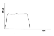
図7の形状のポンプを用いたときの、試料が検出器を通過する粒子数(信号数)を時間あたりで表したものが図9となる。これは室の内壁部において隅部に膜体1が密着しきらないために試料吸引の切れが悪く、検出器を通過する試料の流れが不安定に終わることになる。
そこで、図4のように流通口部に向かって収斂する円錐台形状もしくは角錐台形状にすれば、膜体の作動する距離も少なく、膜体と室内壁略全体が密着しやすく、容量も大きなものが形成できる。
このような形状の室のポンプを用いたときの、試料が検出器が検出器を通過する粒子数(信号数)を時間あたりで表したものが図8となる。これは膜体が室内壁に密着しやすいため、試料吸引の切れが良く検出器を通過する粒子数(信号数)が安定して終わる。
【0020】
膜体と室の内壁とが密着しても、その間に試料等の液体が排出されきらずに残ることもあり得る。そこで室の内壁に流通口部へ連通する細い溝を形成すると、排出されきらなかった液体が溝部を伝って排出することができる。
【0021】
この実施態様では、ポンプ内の試料を排出する際、流通口部21b、22bの開口周縁部には、膜体1の変位によりその流通口部21b、22bから排出される流体の残部、すなわち、内壁部21a、22aと膜体1との間に膜状に残った流体を流通口部21b、22bに導く細い溝部21c、22cがそれぞれ形成されている(図5)。これらの溝部21c、22cは、流通口部21b、22bの開口を中心として放射状に形成されている。
【0022】
なお、上述したように、赤血球検出系に用いられるポンプ11は、1回の作動で血液試料250μlを赤血球検出器33に吸引し、白血球検出系に用いられるポンプ12は、1回の作動で血液試料500μlを白血球検出器34に吸引するので、定量室21・22及び定量室27・28の総容積は前記吸引量と同容積にそれぞれ形成されている。
【0023】
図6のフローチャートに基づいて血球分析装置10の動作を説明する。
まず、ステップS0において各バルブの開閉が初期状態に設定され、陰圧チャンバ13、陽圧チャンバ14が駆動される。なお、バルブV7は陽圧チャンバ14側に切り換えられている。次にステップS1で試料定量機構56が作動され試料採取用ピペット51により試料容器Sから血液50μlが吸引採取される。
次に、ステップS2でバルブV5、V6を開く。これにより検出チャンバ31、32に収納されていた希釈液がそれぞれ陰圧チャンバ13に排出される。
【0024】
〔赤血球測定用試料調整〕
ステップS3では、ステップS2においてピペット51により吸引採取された血液が、希釈液供給チャンバ52から供給される希釈液により25000倍に希釈され検出チャンバ31に移送する。
〔白血球測定用試料調整〕
一方、ステップS4では、ステップS2においてピペット51により吸引採取された血液が、希釈液供給チャンバ52から供給される希釈液とともに検出チャンバ32に移送される。次に、ステップS5で溶血剤供給部4から白血球測定用溶血剤を検出チャンバ32に移送して希釈液と溶血剤とにより500倍に希釈処理される。
【0025】
ステップS6では、バルブV1〜4を開き、バルブV5、6を閉じる。これにより、希釈液供給チャンバ42から供給された希釈液の流れにて検出器33、34の各オリフィス付近の汚れや気泡等が除去される。
【0026】
ステップS7〜9では、バルブV1〜6を閉じ、バルブV7を陰圧チャンバ13側に切り換える。これによりポンプ11、12のそれぞれの室22、28に陰圧が負荷される。ポンプ11、12の内部は、室21、27の各内壁部に密着した膜体1が、陰圧の負荷により室22、28の逆側の各内壁部に密着する。
ポンプ11の室21、22の内容積量250μlが吸引されて検出チャンバ31内の赤血球測定用に希釈処理された血液試料が検出器33を250μl通過することにより赤血球の測定が行われる。
ステップS11及び12では、ポンプ11の室27、28の内容積量500μlが吸引されて検出チャンバ32内の白血球測定用に希釈処理された血液試料が検出器34を500μl通過することにより白血球の測定が行われる。
【0027】
次に、バルブV3とV4を開き、バルブV7を陽圧チャンバ14側に切り換えると、ポンプ内へ吸引した試料が陰圧チャンバーへ排出される。次にバルブV3とV4を閉じ、バルブV5とV6を開くと、検出チャンバ31、32に残った各試料は陰圧チャンバ13に排出される(ステップS10及びS13)。次に、ステップS14では、バルブV5とV6を閉じ、バルブV1〜4を開いて希釈液供給チャンバ42から希釈液を供給して各検出器33、34及び各管路を洗浄する。そしてバルブV1〜4を閉じ、希釈液供給チャンバ52から定量希釈部5を通じて希釈液を充填する。
【0028】
【発明の効果】
本願発明による粒子分析装置では、ポンプによって正確に定量された量の試料流体を安定した流速で検出器に供給することができる。そして特にポンプを膜体とこの膜体で仕切られる室とで構成し、定量された試料流体を、圧力源の切換えによりポンプの膜体を一方の室の内壁に密着した状態から他方の室の内壁に密着した状態へと作動させて両方の室の内容積量から得ることができるので、構成が簡単で測定精度の高い粒子分析装置を提供できる。
【0029】
ポンプが、圧力源が駆動されて膜体が変位したとき、内壁の略全体が前記膜体に密着する形状を備え、膜体の変位により流通口部から排出される流体の残部が残らないように流体流通口部に導く細い溝部を備える、もしくは流通口部の形状を放射状にすることにより、高精度の定量が可能となり特に微量定量に供することができる。
【図面の簡単な説明】
【図1】この発明の一つの実施態様による粒子分析装置としての血球分析装置の概略説明図。
【図2】図1のポンプの正面図。
【図3】図1のポンプの側面図。
【図4】図1のポンプのIV−IV線断面図。
【図5】図1のポンプのV−V線断面図。
【図6】図1の血球分析装置の動作を説明するフローチャート。
【図7】従来のポンプの内部形状を説明する、図4に対応する断面図。
【図8】図4のポンプの定量性能を説明するグラフ。
【図9】図7のポンプの定量性能を説明する、図8に対応するグラフ。
【符号の説明】
1 膜体
2 ケース
10 血球分析装置(粒子分析装置)
11、12 ポンプ(定量供給手段)
13 陰圧チャンバ(圧力源)
14 陽圧チャンバ(圧力源)
33、34 検出器
21、22 室[0001]
BACKGROUND OF THE INVENTION
The present invention relates to a particle analyzer, and more particularly to a particle analyzer that measures the number of particles such as blood cells contained in a sample such as urine and blood.
[0002]
[Prior art]
As a method for measuring particles such as blood cells, a flow cytometry method and an electric resistance method are well known. For example, in the electrical resistance method, an electrical signal generated when a minutely quantified blood sample is supplied to a detector, that is, a micropore (a rectifying element having a function as an orifice) through which a current flows, and passes through the micropore. The change is detected to obtain the number of particles such as blood cells and the particle size distribution.
Such a measurement method stabilizes the flow rate of the sample fluid flowing through the detector, and the number of particles cannot be measured accurately unless the amount is accurately quantified.
[0003]
To quantify the amount of sample fluid that flows through the detector,
(i) A quantification method in which a flow passage is provided with a detection portion for quantitatively detecting the amount of sample fluid flowing to the detector. As a quantitative detection portion, a manometer using a mercury U-shaped tube or a sphere (Japanese Utility Model Publication No. 62-22830) Is known).
(ii) A quantification method in which the time for measuring the sample fluid is set to a certain time, that is, based on the measurement time.
(iii) A method in which a sample is pressurized or sucked by a quantitative supply means of a syringe or a peristaltic pump (peristalrac pump) and the amount of sample fluid flowing to the detector is set to a predetermined amount.
[0004]
[Problems to be solved by the invention]
However, in the method (i), a detection unit must be provided in the flow path, and a blood sample or the like is likely to be contaminated and a detection failure may occur. Since the mercury U-shaped tube uses mercury, which is a poison, handling is troublesome, and the manometer using the sphere has a problem that the structure is complicated and malfunction of the sphere itself occurs.
In the method (ii), it is necessary to make the flow rate exactly constant. If the liquid temperature of the sample changes, the flow rate changes, and if the microscopic pores become small due to contamination on the detection part, there is a problem that the flow rate decreases and the quantitative accuracy cannot be ensured.
In the above method (iii), it is necessary to provide a driving unit and a control unit such as a stepping motor for flowing a predetermined amount of sample fluid at a stable flow rate through a syringe or a squeezing pump, which is complicated and expensive. There is a problem that the tube and the tube must be changed regularly.
[0005]
The present invention has been made in view of such circumstances, and provides a particle analyzer that can supply an accurately quantified amount of sample fluid to a detector at a stable flow rate and has a simple configuration. Is.
[0006]
[Means for Solving the Problems]
The present invention relates to a particle analyzer for measuring the number of particles in a quantified sample fluid, and as a quantitative supply means for flowing a certain amount of sample fluid to a detector, a membrane body, and a chamber partitioned by the membrane body A flow port is formed on the inner wall of each chamber, the flow port of one chamber is in communication with a pressure source, and the flow port of the other chamber is in communication with a detector. By switching the pressure source, this pump is operated from a state in which the membrane body is in close contact with the inner wall of one chamber to a state in which it is in close contact with the inner wall of the other chamber, and the sample fluid corresponding to the internal volume of both chambers is supplied. and flow to the detector to provide a particle analyzer, characterized in that configured to measure the number of particles in the sample fluid.
[0007]
The pump in the present invention is a diaphragm pump that is widely used for air sources, liquid pumps, and the like and sucks and discharges fluid by the operation of the membrane body. Specifically, the membrane body and the membrane body are arranged on both sides. And a pressure source for operating the film body.
[0008]
The amount to be sucked and discharged by such a pump is determined by the size of the membrane and the size that the membrane can operate. Although this amount does not satisfy the sufficient quantitative property, it can be defined to some extent, so that it is used in various types of analyzers as a simple means for sucking and discharging a sample or the like. For example, sample agitation by suction discharge (see JP-A-5-40123), sample filling (see JP-A-5-232011), mixing of plural samples, washing, and the like.
[0009]
In this invention, the amount of the sample to be sucked / discharged is switched from the state in which the film body is in close contact with the chamber to one side by negative pressure or positive pressure until the film body is in close contact with the opposite chamber. The amount of internal volume of the chamber can be defined.
Since a pump capable of accurately quantifying by using a chamber in which the film body can be in close contact is used as the quantitative supply means, a complicated mechanism in the above method is not required, and there is no problem of contamination of the detection unit.
[0010]
Examples of the particles in the sample fluid in the present invention include red blood cells, platelets and white blood cells in blood diluted at a predetermined dilution rate, and suspended substances in urine.
Examples of the detector in the present invention include a flow cytometry method and an electric resistance method in which blood cells in a blood sample are analyzed particles and the number of particles and particle size distribution are obtained.
[0011]
DETAILED DESCRIPTION OF THE INVENTION
1 to 6 show a
The overall configuration of the
[0012]
The
[0013]
The sample
[0014]
A red blood cell
The
[0015]
One
A
The
[0016]
2 to 5 show a pump 11 (12 has the same configuration and will not be described) according to one embodiment of the present invention.
The
The
[0017]
The
[0018]
The shapes of the
In the columnar chamber pump as shown in FIG. 7, there are cases where the vicinity of the circulation port is first brought into close contact by the pressure, and the peripheral portion is not fully attached. When this happens, the amount of suction or discharge corresponding to the volume of the corner that has not been in close contact is reduced, and the quantitativeness is reduced.
[0019]
FIG. 9 shows the number of particles (number of signals) through which the sample passes the detector when the pump having the shape shown in FIG. 7 is used. This is because the
Therefore, if the truncated cone shape or the truncated pyramid shape converges toward the circulation port as shown in FIG. 4, the working distance of the membrane body is small, the membrane body and the entire indoor wall are easily in close contact, and the capacity is large. Things can be formed.
FIG. 8 shows the number of particles (the number of signals) that the sample passes through the detector when the sample is used in the chamber-shaped pump. This is because the film body easily adheres to the indoor wall, so that the sample suction is well cut and the number of particles (number of signals) passing through the detector ends stably.
[0020]
Even if the film body and the inner wall of the chamber are in close contact with each other, liquid such as a sample may remain without being discharged. Therefore, if a narrow groove communicating with the circulation port is formed on the inner wall of the chamber, the liquid that could not be discharged can be discharged through the groove.
[0021]
In this embodiment, when the sample in the pump is discharged, the remaining portion of the fluid discharged from the
[0022]
As described above, the
[0023]
The operation of the
First, in step S0, the opening and closing of each valve is set to an initial state, and the
Next, the valves V5 and V6 are opened in step S2. As a result, the diluents stored in the
[0024]
[Sample preparation for red blood cell measurement]
In
[Sample preparation for leukocyte measurement]
On the other hand, in step S4, the blood aspirated and collected by the
[0025]
In step S6, the valves V1 to V4 are opened and the valves V5 and 6 are closed. As a result, dirt, bubbles, etc. near the orifices of the
[0026]
In steps S7 to S9, the valves V1 to V6 are closed, and the valve V7 is switched to the
Red blood cells are measured by passing 250 μl of the blood sample diluted in the
In Steps S11 and S12, the blood volume of 500 μl of the
[0027]
Next, when the valves V3 and V4 are opened and the valve V7 is switched to the positive pressure chamber 14, the sample sucked into the pump is discharged into the negative pressure chamber. Next, when the valves V3 and V4 are closed and the valves V5 and V6 are opened, the samples remaining in the
[0028]
【The invention's effect】
In the particle analyzer according to the present invention, an amount of sample fluid accurately quantified by the pump can be supplied to the detector at a stable flow rate. In particular, the pump is composed of a membrane body and a chamber partitioned by the membrane body, and the quantified sample fluid is changed from a state in which the pump membrane body is brought into close contact with the inner wall of one chamber by switching the pressure source. Since it can be obtained from the internal volume of both chambers by operating in close contact with the inner wall, a particle analyzer with a simple configuration and high measurement accuracy can be provided.
[0029]
When the pressure source is driven and the film body is displaced, the pump has a shape in which substantially the entire inner wall is in close contact with the film body so that the remaining portion of the fluid discharged from the flow port does not remain due to the displacement of the film body. By providing a narrow groove portion leading to the fluid circulation port portion or by making the shape of the circulation port radial, high-precision quantification becomes possible, and in particular, it can be used for minute quantification.
[Brief description of the drawings]
FIG. 1 is a schematic explanatory diagram of a blood cell analyzer as a particle analyzer according to one embodiment of the present invention.
FIG. 2 is a front view of the pump of FIG.
3 is a side view of the pump of FIG. 1. FIG.
4 is a sectional view of the pump of FIG. 1 taken along the line IV-IV.
5 is a cross-sectional view of the pump of FIG. 1 taken along line VV.
FIG. 6 is a flowchart for explaining the operation of the blood cell analyzer of FIG. 1;
FIG. 7 is a cross-sectional view corresponding to FIG. 4 for explaining the internal shape of a conventional pump.
FIG. 8 is a graph illustrating the quantitative performance of the pump of FIG.
9 is a graph corresponding to FIG. 8 for explaining the quantitative performance of the pump of FIG. 7;
[Explanation of symbols]
1
11, 12 Pump (quantitative supply means)
13 Negative pressure chamber (pressure source)
14 Positive pressure chamber (pressure source)
33, 34
Claims (4)
一定量の試料流体を検出器に流すための定量供給手段として、膜体と、この膜体で仕切られる室とからなり、各室の内壁には流通口部が形成され、一方の室の流通口部が圧力源と連通され、他方の室の流通口部が検出器と連通されてなるポンプを備え、
さらにこのポンプは、圧力源の切換えにより、膜体を一方の室の内壁に密着した状態から他方の室の内壁に密着した状態へと作動させ、両方の室の内容積量に対応する試料流体を検出器に流して試料流体中の粒子数を測定するよう構成されたことを特徴とする粒子分析装置。 In a particle analyzer that measures the number of particles in a quantified sample fluid,
As a quantitative supply means for flowing a fixed amount of sample fluid to the detector, it consists of a membrane body and a chamber partitioned by this membrane body. A flow port is formed on the inner wall of each chamber, and the flow in one chamber A pump in which the mouth is in communication with the pressure source and the flow port in the other chamber is in communication with the detector;
Furthermore this pump, by switching the pressure source, is operated from the state of being in close contact with the inner wall of the one chamber of the film body to the state of being in close contact with the inner wall of the other chamber, the sample fluid corresponding to the internal volume of both chambers it was configured to be flow to the detector for measuring the number of particles in the sample fluid particle analyzer according to claim.
Priority Applications (1)
| Application Number | Priority Date | Filing Date | Title |
|---|---|---|---|
| JP35387297A JP3792034B2 (en) | 1997-12-22 | 1997-12-22 | Particle analyzer |
Applications Claiming Priority (1)
| Application Number | Priority Date | Filing Date | Title |
|---|---|---|---|
| JP35387297A JP3792034B2 (en) | 1997-12-22 | 1997-12-22 | Particle analyzer |
Publications (2)
| Publication Number | Publication Date |
|---|---|
| JPH11183359A JPH11183359A (en) | 1999-07-09 |
| JP3792034B2 true JP3792034B2 (en) | 2006-06-28 |
Family
ID=18433798
Family Applications (1)
| Application Number | Title | Priority Date | Filing Date |
|---|---|---|---|
| JP35387297A Expired - Fee Related JP3792034B2 (en) | 1997-12-22 | 1997-12-22 | Particle analyzer |
Country Status (1)
| Country | Link |
|---|---|
| JP (1) | JP3792034B2 (en) |
Families Citing this family (4)
| Publication number | Priority date | Publication date | Assignee | Title |
|---|---|---|---|---|
| JP5161703B2 (en) * | 2008-08-26 | 2013-03-13 | シスメックス株式会社 | Reagent preparation device, sample processing device, and reagent preparation method |
| JP6014072B2 (en) | 2014-03-20 | 2016-10-25 | 住友ゴム工業株式会社 | Diaphragm fixing structure, diaphragm pump and valve device including the same |
| JP5952848B2 (en) | 2014-03-20 | 2016-07-13 | 住友ゴム工業株式会社 | Diaphragm fixing structure, diaphragm pump and valve device including the same, and diaphragm fixing method |
| US11169060B2 (en) * | 2015-11-18 | 2021-11-09 | Beckman Coulter, Inc. | Filtering device for analyzing instrument |
-
1997
- 1997-12-22 JP JP35387297A patent/JP3792034B2/en not_active Expired - Fee Related
Also Published As
| Publication number | Publication date |
|---|---|
| JPH11183359A (en) | 1999-07-09 |
Similar Documents
| Publication | Publication Date | Title |
|---|---|---|
| CA2489177C (en) | A disposable cartridge for characterizing particles suspended in a liquid | |
| US8573033B2 (en) | Method for characterizing particles in liquid using a dual sample cartridge | |
| US8741234B2 (en) | Disposable cartridge for fluid analysis | |
| US8980635B2 (en) | Disposable cartridge for fluid analysis | |
| US8741233B2 (en) | Disposable cartridge for fluid analysis | |
| US8028566B2 (en) | Dual sample cartridge and method for characterizing particles in liquid | |
| US8741235B2 (en) | Two step sample loading of a fluid analysis cartridge | |
| JP2010508514A (en) | Device for aspirating and dispensing liquids in automated analyzers | |
| JP4704036B2 (en) | Disposable cartridge for characterizing particles suspended in liquid | |
| JP3792034B2 (en) | Particle analyzer | |
| JPH09318522A (en) | Particle detector and partcle analyzer | |
| JP3880181B2 (en) | Blood analyzer | |
| EP3572816B1 (en) | Automated analyzer, liquid discharge method for automated analyzer, and three-way solenoid valve | |
| JP2000199763A (en) | Sample treatment apparatus | |
| JPS6252254B2 (en) | ||
| JPH0622202Y2 (en) | Particle detector | |
| JPH04369461A (en) | Particle measuring apparatus | |
| JPH0614956U (en) | Particle detector | |
| JPH0614955U (en) | Particle detector | |
| JPH02189443A (en) | Method and apparatus for measuring number of particles or concentration of dissolved substance |
Legal Events
| Date | Code | Title | Description |
|---|---|---|---|
| A521 | Request for written amendment filed |
Free format text: JAPANESE INTERMEDIATE CODE: A523 Effective date: 20040909 |
|
| A621 | Written request for application examination |
Free format text: JAPANESE INTERMEDIATE CODE: A621 Effective date: 20040909 |
|
| A977 | Report on retrieval |
Free format text: JAPANESE INTERMEDIATE CODE: A971007 Effective date: 20050729 |
|
| A131 | Notification of reasons for refusal |
Free format text: JAPANESE INTERMEDIATE CODE: A131 Effective date: 20050809 |
|
| A521 | Request for written amendment filed |
Free format text: JAPANESE INTERMEDIATE CODE: A523 Effective date: 20051011 |
|
| TRDD | Decision of grant or rejection written | ||
| A01 | Written decision to grant a patent or to grant a registration (utility model) |
Free format text: JAPANESE INTERMEDIATE CODE: A01 Effective date: 20060322 |
|
| A61 | First payment of annual fees (during grant procedure) |
Free format text: JAPANESE INTERMEDIATE CODE: A61 Effective date: 20060404 |
|
| R150 | Certificate of patent or registration of utility model |
Free format text: JAPANESE INTERMEDIATE CODE: R150 |
|
| FPAY | Renewal fee payment (event date is renewal date of database) |
Free format text: PAYMENT UNTIL: 20090414 Year of fee payment: 3 |
|
| FPAY | Renewal fee payment (event date is renewal date of database) |
Free format text: PAYMENT UNTIL: 20120414 Year of fee payment: 6 |
|
| FPAY | Renewal fee payment (event date is renewal date of database) |
Free format text: PAYMENT UNTIL: 20120414 Year of fee payment: 6 |
|
| FPAY | Renewal fee payment (event date is renewal date of database) |
Free format text: PAYMENT UNTIL: 20150414 Year of fee payment: 9 |
|
| R250 | Receipt of annual fees |
Free format text: JAPANESE INTERMEDIATE CODE: R250 |
|
| LAPS | Cancellation because of no payment of annual fees |