JP3791663B2 - Omnidirectional moving vehicle and its control method - Google Patents
Omnidirectional moving vehicle and its control method Download PDFInfo
- Publication number
- JP3791663B2 JP3791663B2 JP2000007969A JP2000007969A JP3791663B2 JP 3791663 B2 JP3791663 B2 JP 3791663B2 JP 2000007969 A JP2000007969 A JP 2000007969A JP 2000007969 A JP2000007969 A JP 2000007969A JP 3791663 B2 JP3791663 B2 JP 3791663B2
- Authority
- JP
- Japan
- Prior art keywords
- vehicle
- drive
- steering shaft
- driving
- shaft
- Prior art date
- Legal status (The legal status is an assumption and is not a legal conclusion. Google has not performed a legal analysis and makes no representation as to the accuracy of the status listed.)
- Expired - Fee Related
Links
Images

Classifications
-
- G—PHYSICS
- G05—CONTROLLING; REGULATING
- G05D—SYSTEMS FOR CONTROLLING OR REGULATING NON-ELECTRIC VARIABLES
- G05D1/00—Control of position, course, altitude or attitude of land, water, air or space vehicles, e.g. using automatic pilots
- G05D1/02—Control of position or course in two dimensions
- G05D1/021—Control of position or course in two dimensions specially adapted to land vehicles
- G05D1/0268—Control of position or course in two dimensions specially adapted to land vehicles using internal positioning means
- G05D1/0272—Control of position or course in two dimensions specially adapted to land vehicles using internal positioning means comprising means for registering the travel distance, e.g. revolutions of wheels
-
- G—PHYSICS
- G05—CONTROLLING; REGULATING
- G05D—SYSTEMS FOR CONTROLLING OR REGULATING NON-ELECTRIC VARIABLES
- G05D1/00—Control of position, course, altitude or attitude of land, water, air or space vehicles, e.g. using automatic pilots
- G05D1/02—Control of position or course in two dimensions
- G05D1/021—Control of position or course in two dimensions specially adapted to land vehicles
- G05D1/0268—Control of position or course in two dimensions specially adapted to land vehicles using internal positioning means
- G05D1/027—Control of position or course in two dimensions specially adapted to land vehicles using internal positioning means comprising intertial navigation means, e.g. azimuth detector
Landscapes
- Engineering & Computer Science (AREA)
- Aviation & Aerospace Engineering (AREA)
- Radar, Positioning & Navigation (AREA)
- Remote Sensing (AREA)
- Physics & Mathematics (AREA)
- General Physics & Mathematics (AREA)
- Automation & Control Theory (AREA)
- Steering Control In Accordance With Driving Conditions (AREA)
- Power Steering Mechanism (AREA)
- Steering-Linkage Mechanisms And Four-Wheel Steering (AREA)
- Control Of Position, Course, Altitude, Or Attitude Of Moving Bodies (AREA)
- Gear Transmission (AREA)
Description
【0001】
【発明の属する技術分野】
この発明は、車両の旋回速度、あるいは進行方向を変更する際、あるいは停止状態から走行、旋回を開始する際に、例えば、車輪の向きを変更するなどの車両の走行準備のための待機時間を必要とせず、任意の車両姿勢から、任意の方向へ即座に移動、旋回を開始、もしくは移動動作の途中においても移動の方向、旋回の速度を変更することができるような、または学術的にホロノミックな移動特性を有すると表現される、全方向移動車両とその制御方法に関する。
【0002】
【従来の技術】
平面上を移動する全方向移動車両とは、その車両の進行方向及び横方向への移動速度と、車両の鉛直軸まわりの角速度,すなわち車両の姿勢変化、の合計3自由度を制御できる車両であり、これに関しては多くの発明が知られている。それらの全方向移動車両は次の二つの種類に大別される。第一の種類の車両は、学術的には非ホロノミックである車両と呼ばれる車両である。
【0003】
この第一の種類の車両においては、車両の走行方向を変更する、または旋回動作に移る際に、例えば各車輪の方向変換などの車両内部の一部の機構の設定を変更するための待機動作、および時間が必要となる。この車両は2自由度を有する機構であり、前記車両の3自由度を同時にかつそれぞれ独立に制御することはできず、前記車両の3自由度のうちの2つを順番に選択していくことによって、最終的に車両の3自由度を制御すると見なされる。
【0004】
従って例えば、待機時間なしで、直角の経路に追従することはできず、円弧状に走行するか、もしくは、角にて一時停止、待機時間を経て再び走行を開始するといったことが必要となる。この第一の種類に分類される車両には、全輪操舵型全方向移動車両などが挙げられる。
【0005】
これに対して、第二の種類の車両は学術的には、ホロノミックである車両と呼ばれるもので、この種類の車両は車両内部機構の設定変更の必要はなく、車両の任意の姿勢、任意の位置から即座に全方向への移動、旋回が開始可能であり、車両の3自由度を同時に、かつそれぞれ独立に制御できることが大きな特徴である。これに分類される車両には、球型の車輪を使用した全方向移動車両、あるいは大車輪の周囲に横方向に自由に回転するローラを多数配置した特殊車輪を使用する全方向移動車両などがある。
【0006】
さらに特開平9-164968号公報に記載され、同一出願人によって提案された車両も、同様に第二の種類の全方向移動車両に分類されるもので、これはキャスタの形態をした車輪の車輪軸と、操舵軸の両方をアクチュエータにてそれぞれ独立に駆動し、かつこの駆動輪を2輪以上備えることで前記所定の3自由度の全方向移動を実現するものであった。この特開平9-164968号公報に記載された発明による車輪機構よれば、通常の形態のタイヤ(ゴムタイヤや空気圧タイヤなど)の装着が可能であるので、滑らかで、俊敏な全方向移動動作を実現することが可能である。
【0007】
【発明が解決しようとする課題】
しかしながら、前述の特開平9-164968号公報に記載された発明において使用されている車輪機構では、連続的に無限回数回転する操舵軸を有するため、配線上の問題から、各車輪機構の車輪軸、操舵軸を駆動する2つのアクチュエータは、両方とも車両本体上に設置され、その回転運動は歯車などの伝達機構を介して伝達される。このことから、2つのアクチュエータの間に速度の干渉が生じる問題がある。
【0008】
つまり、車輪駆動用アクチュエータを停止した状態にて、車輪の方向を変更するように操舵軸のアクチュエータのみを駆動しても、操舵および車輪の両方が回転してしまう現象が起こる。一方、操舵軸駆動用アクチュエータを停止した状態にて、車輪駆動用アクチュエータを駆動した場合には、車輪のみが回転する.これから、操舵軸駆動用アクチュエータから、車輪駆動用アクチュエータへの一方向の速度干渉が生じていることになる。
【0009】
前述の発明においてはこの速度干渉を除去するため、操舵軸の回転速度の所定の割合の回転速度をあらかじめ車輪軸のアクチュエータに加算して運動制御を行う必要があった。つまり、この速度干渉を除去するために、実際に車輪に必要な最大回転速度よりも早くまわるアクチュエータを車輪駆動用として搭載する必要があった。
【0010】
さらに、車輪を駆動するためのトルクは、操舵軸の伝達機構のある部分、例えばひとつの歯車を支点として作用するので、操舵軸が回転しているか、停止しているかにかかわらず、車輪に伝達されるトルクを支えるだけのトルクを操舵軸駆動用アクチュエータも発生しなくてはならないという問題があった。これは、加減速時や段差昇降時などには急激なトルクが操舵軸にかかり、これは操舵軸用アクチュエータにとって外乱に他ならない。
【0011】
そして、この車輪用アクチュエータからのトルクによって、操舵軸に速度誤差が生じた場合には、車両の走行方向がずれることになるので、車両の走行誤差を生む結果となり、この誤差の発生は重要な問題であった。
【0012】
また、同特開平9-164968号公報に記載された発明において、双輪キャスタの形態の駆動ユニットに車両本体の旋回用のアクチュエータを付加した全方向移動車両も提案されている。この車両は、二輪の駆動輪、及び駆動ユニットの操舵軸を駆動する3つのアクチュエータにより、車両の並進、回転の運動を制御できるもので、単輪キャスタを複数使用した車両の過拘束の状態(自由度よりも多くの数のアクチュエータにて制御する状態)を回避するものである。
【0013】
この双輪キャスタの形態においては、操舵軸用のアクチュエータは駆動ユニット上に設置されており、車両が旋回動作を行わないとき(単純な並進運動など)であっても、駆動ユニットの方向変化の影響を補正するために、駆動ユニットの回転と逆方向に車両本体を駆動する必要があるため、車両本体の旋回軸用アクチュエータの制御計算に並進方向の運動を考慮する必要があった。またこれは、制御システムの複雑化を招くばかりでなく、必要以上に大きな容量を有する車両本体の旋回軸用アクチュエータを搭載する必要があった。
【0014】
つまり上記の2つの問題は、車両を駆動する複数のアクチュエータ間の干渉が生じることにより、車両の走行精度を劣化させるだけでなく、その制御系を複雑にし、かつアクチュエータの容量を増大させていることになる。
【0015】
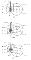
以上の問題点に関して、図を用いて、以下に詳述する。従来のキャスタ型の一例の駆動輪機構の側面図を図19に、および下面図を図20にそれぞれ示す。この例は、同特開平9-164968号公報に記載された実施例の一部変形例である。
【0016】
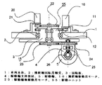
図19および図20において、車両本体1には、回転板3を有する操舵軸13が操舵軸用軸受2によって鉛直軸周りの回転を自在に支持されている。さらに回転板3に固定された駆動輪支持部材4によって軸支された駆動輪5が、操舵軸回転軸心から駆動輪5の転がり方向に距離sだけ離間した位置に配置されている。操舵軸駆動用モータ10、及び駆動輪軸駆動用モータ20は、共に車両本体1に固定されるように搭載される。操舵軸13は操舵軸駆動用モータ10によって、モータ軸歯車11、操舵軸が備える回転板歯車12を介して回転駆動され、また、駆動輪5は駆動輪軸駆動用モータ20によって、モータ軸歯車21、平歯車22、平歯車23、平歯車24、ベベル歯車25、ベベル歯車26を介して回転駆動される。
【0017】
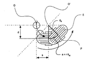
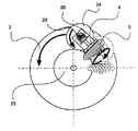
特開平9-164968におけるこの駆動輪の動作目的は、図21に示すように、操舵軸の中心、つまり、操舵軸13が備える回転板3の中心位置に水平面内の任意の方向への速度を発生させることである。つまり、駆動輪5の回転によって、駆動輪の転がりの方向への速度Vwを発生させ、また、操舵軸の回転による接地点を中心とした円運動の角速度ωsによって車輪の転がりの方向と直交する方向への速度Vsを発生させ、これらの互いに直交する二つの速度の合成により結果的に、任意の方向への任意の大きさの速度Vが操舵軸中心に発生するものである。
【0018】
ここで、上述の動作は駆動輪軸駆動用モータ20が回転板3に搭載された状態にて駆動輪5が駆動される場合には、VsおよびVwは駆動輪軸駆動用モータ、操舵軸駆動用モータにより、それぞれ独立して制御が可能である。しかし、実際の車輪の設計においては、操舵軸が連続的に複数回転の動作を要求されることにより、その配線の問題から、車輪軸駆動用、操舵駆動用のモータは共に、車両本体に搭載される場合がほとんどである。このとき、操舵軸駆動用モータ10の速度が駆動輪5の速度に干渉する問題が生じる。これについて以下に詳細に述べる.
図22に示すように、操舵軸駆動用モータ10を、例えば回転板3が、紙面上の反時計方向に回転するように駆動される場合を考える。このとき、駆動輪軸駆動用モータ20は回転しないにもかかわらず、操舵軸駆動用モータ10のみの動作によって車輪5はある角度回転してしまう現象が生じる。これは、歯車23は車輪駆動用モータ20、モータ軸歯車21、歯車22と共に車両本体1に対して停止した状態を保っている、つまり同図において紙面に固定されている状態である。
【0019】
回転板3が回転することによって、回転板3上に配置、支持された歯車24は歯車23のまわりを遊星歯車の要領で回転するので、その結果、歯車24は回転板3に対してある角度回転することになり、駆動輪5もこれに応じた角度だけ回転する。これは駆動輪軸駆動用モータ20が停止していない状態においても常に発生し、回転板3のある割合の回転が駆動輪5に加算されることになる。
【0020】
このときの回転板3の回転角度に対する駆動輪5の回転角度の比は、歯車23、24、およびベベル歯車25、26の歯数比によって決定する一定値であり、あらかじめこの回転を相殺するように駆動輪軸駆動用モータ20への速度指令値に、操舵軸駆動用モータ10への速度指令値の所定の割合の速度を加算することで、上記、速度干渉の影響を除去する方法が考えられる。
【0021】
特開平9-164968の発明の実施において、図21に示すような動作を達成するためにはこの速度干渉の除去手段は必須であった。このことから、車輪軸駆動用モータ20に駆動輪5を最高回転数で駆動する以上の早い回転数が要求され、必要以上に大きな容量のモータを搭載する必要があった。
【0022】
さらに、例えば駆動輪5が段差を乗り越える状態を考えると、段差の角に駆動輪5の一端が接触した状態の時には、車輪軸駆動用モータは段差を乗り上がるために、大きなトルクを発生する。しかし、このとき駆動輪5は一時ロックされた状態になり、車両を押し上げるに十分なトルクが伝達されるまで駆動輪5は回転できない。このとき、駆動輪5に伝えられるトルクは、平歯車23、24を介して回転板3を回転させようとする方向に作用し、操舵軸駆動用モータ10にまで伝わる。この結果、回転板3に角度誤差が発生するか、さらに悪い場合には、操舵軸駆動用モータ10が駆動輪軸駆動用モータ20に負けて回転させられてしまう現象が発生する。
【0023】
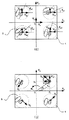
また、図23には特開平9-164968に記載された異なる実施例に関わる構成を示す。この構成においては、双輪キャスタ型の駆動ユニットを用いることで、3つのアクチュエータにより、ホロノミックな全方向移動を達成する。これは、駆動ユニット55上に搭載される操舵軸駆動用モータ150により、車両本体1が駆動ユニット55に対して回転する。図24にその動作の様子を示す。これは、駆動ユニット55と車両本体1の角度が90度ずれた状態から、車両の横方向の並進運動を行った例である。
【0024】
このとき、車両本体1自体の姿勢を変化させる必要はないにもかかわらず、駆動ユニット55は通常のキャスタと同様な動作を行うため、その姿勢は大きく変化する。この駆動ユニット55の回転の影響を補正するために、操舵軸駆動用モータ150は車両本体1を逆方向に回転させることで、車両本体1の姿勢を一定に保たなければならない。
【0025】
これより、駆動ユニット55の回転を考慮した最大の速度、つまり、車両本体1の最大旋回速度に駆動ユニット55の最大旋回速度を加算した速度、が操舵軸駆動用モータ150に要求されることとなる。また、駆動ユニット55全体を旋回させる必要があるので、大きな駆動エネルギーを必要とし、バッテリにより走行する車両においては、電力の消費が大きく、一回の充電あたりの走行時間を短縮する要因にもなる。
【0026】
この発明は上記の従来の全方向移動車両の有する問題点を解決するためになされたもので、この発明の課題は、車両を駆動するそれぞれのアクチュエータ間の速度干渉を除去することにより、制御系を簡素化し、さらには駆動輪軸駆動用モータ、及び、車両旋回駆動用モータの小容量化を図ることにある。
【0027】
さらに、操舵軸にかかる外乱トルクを操舵軸駆動用アクチュエータにまで伝えることなく、操舵軸用のアクチュエータの更なる小容量化を図ることにある。
【0028】
ひいては、全方向移動車両自身の小型、軽量化、低価格化と、エネルギー消費の低減、バッテリーによる自律走行車両などの長時間走行、あるいはバッテリーの小型、軽量化などを図ることにある。
【0029】
【課題を解決するための手段】
前述の問題を解決するために、請求項1の発明においては、車両本体と、車両本体に取り付けられ,操舵軸と同操舵軸駆動用アクチュエータと,駆動輪と同駆動輪軸駆動用アクチュエータとを有する駆動ユニットと、前記車両本体に設けられ,前記操舵軸を軸支するための操舵軸回転用軸受とを備えた全方向移動車両において、前記操舵軸は、車両本体に取り付けられた操舵軸駆動用アクチュエータによって第一の動力伝達手段を介して駆動され、かつその下方に前記駆動輪を,軸受を介して軸支するための駆動輪支持部材を設けてなり、前記駆動輪は、車両本体に取り付けられた駆動輪軸駆動用アクチュエータによって第二の動力伝達手段を介して回転駆動され、かつ前記駆動輪支持部材に軸支されて操舵軸と共に車両本体に対して鉛直軸周りに動き得るようになし、さらに、操舵軸の回転軸心を含みかつ駆動輪軸と直交する平面から所定の距離(d)だけ離間した位置であって,操舵軸回転軸心から水平方向に所定の距離(s)だけ離間した位置において,駆動輪軸と操舵軸が互いに交差しないように水平軸周りに回動自在にしてなるものとする。
【0030】
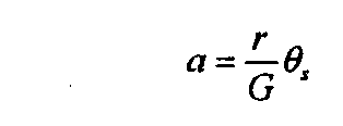
また、請求項2の発明によれば、請求項1に記載の全方向移動車両において、前記第二の動力伝達手段は、前記駆動輪軸駆動用アクチュエータによって前記操舵軸とは独立的に鉛直軸周りに動き得る動力伝達部Aと、この動力伝達部Aに連結し,操舵軸と共に鉛直軸周りに動き得る動力伝達部Bとを有してなるものとし、この動力伝達部Bの減速比をG(但し、G>1にて減速)とし、前記駆動輪の半径をrとしたとき、前記所定の距離(d)は、次式(数4)の関係を満たすものとする。
【0031】
【数4】
【0032】
また、請求項3の発明によれば、請求項2に記載の全方向移動車両において、前記駆動輪支持部材は、操舵軸に接続固定された操舵軸接続部材と、この操舵軸接続部材に軸支された歯車の回転軸と同一回転軸に軸支されて鉛直面内に回転できるように軸支され,かつ前記駆動輪を軸支する駆動輪支持用リンク部材とを備え、さらに、前記操舵軸と共に鉛直軸周りに動き得る動力伝達部Bを、前記歯車に連結し,操舵軸と共に水平軸周りに動き得る駆動輪用歯車からなる動力伝達部bに代えてなり、かつ、前記操舵軸と駆動輪支持用リンク部材との間に、駆動輪の床面走行中における振動を吸収するための振動吸収手段を設けたものとする。
【0033】
上記構成によれば、床面に若干の凹凸があっても、駆動輪が接地した状態を保つことができることから、特に、駆動輪を複数設けた場合において、十分な車両駆動力、安定性を保持することができ、走行性能が向上する。
【0034】
さらに、請求項4の発明によれば、請求項3に記載の全方向移動車両において、前記振動吸収手段は、ばねを備えるものとし、このばねと並列に直線駆動型のポテンシオメータなどの直線位置検出器を設け、ばねの変位を測定することにより駆動輪に作用する垂直抗力を測定し、これにより、搭載物を含めた車両全体の重量または重心位置等を測定可能な車両重量等測定手段を備えたものとする。上記構成により、各駆動輪機構に搭載されたサスペンションのばねの変位を計測することで、車両の総重量、重心位置などを推定することができ、車両の安定性をさらに向上させることができる。
【0035】
さらに、請求項5の発明によれば、請求項3に記載の全方向移動車両において、前記操舵軸と共に回転する振動吸収手段の変位に応じて上下動を行う可動子を操舵軸の中心を貫通して設け、かつ操舵の動作により回転を行わない部位に配設置したポテンシオメーターなどの直線位置検出器を設け、この直線位置検出器にて前記可動子の変位を計測することにより前記振動吸収手段の変位を測定し、これにより、搭載物を含めた車両全体の重量または重心位置等を測定可能な車両重量等測定手段を備えたものとする。上記により、サスペンションのばねの変位を計測するセンサを車両本体に設置することが可能であるので、回転部に配線を渡す必要がなくなり、装置の信頼性を向上させることができる。
【0036】
また、請求項6の発明によれば、請求項1ないし5のいずれかに記載の全方向移動車両の制御方法であって、車両本体は、前記駆動ユニットを2つ以上備え、車両基準点に仮想的に設置された車両基準座標系に対するそれぞれの駆動ユニットの操舵軸の位置(座標)、姿勢情報を用いて、次式(数5)に従って、各駆動ユニットにおける操舵軸駆動用アクチュエータおよび駆動輪軸駆動用アクチュエータの回転角速度を制御することとする。
【0037】
【数5】
【0038】
次に、請求項7の発明によれば、車両本体と、車両本体に取り付けられ,操舵軸と駆動輪とを有する複数個の駆動ユニットと,この複数個の駆動ユニットにおける操舵軸と駆動輪とを駆動するための駆動手段を備えた駆動セットと、この駆動セットに設けられ,前記車両本体の鉛直軸まわりの回転を自在にして支持するための車両本体回転用軸受と車両本体回転駆動用アクチュエータと同動力伝達手段とを備えた全方向移動車両であって、前記複数個の各操舵軸は、前記駆動セットに取り付けられた操舵軸駆動用アクチュエータによって,ベルトやチェーンなどの動力伝達手段を介して一括駆動され、かつその下方に前記駆動輪を,軸受を介して軸支するための駆動輪支持部材を設けてなり、前記複数個の各駆動輪は、前記駆動セットに取り付けられた駆動輪軸駆動用アクチュエータによって,ベルトやチェーンなどの動力伝達手段を介して一括駆動され、かつ前記駆動輪支持部材に軸支されて操舵軸と共に車両本体に対して鉛直軸周りに動き得るようになし、さらに、操舵軸の回転軸心を含みかつ駆動輪軸と直交する平面から所定の距離(d)だけ離間した位置であって,操舵軸回転軸心から水平方向に所定の距離(s)だけ離間した位置において,駆動輪軸と操舵軸が互いに交差せぬように水平軸周りに回動自在にしてなるものとする。
【0039】
また、請求項8の発明によれば、請求項7に記載の全方向移動車両の制御方法であって、駆動輪軸駆動用アクチュエータと操舵軸駆動用アクチュエータおよび車両本体回転駆動用アクチュエータの回転角速度を、次式(数6)に基づいて制御することにより、駆動ユニット及び車両本体の並進方向の速度とその方向を制御し、かつ、車両本体の方向を制御することとする。
【0040】
【数6】
【0041】
次に、請求項9ないし10の発明は、制御方法のさらなる改良であって、請求項9の発明においては、請求項8に記載の全方向移動車両の制御方法において、車両本体に角度検出器を固定して設け、この角度検出器の軸を操舵軸駆動用アクチュエータの動力伝達手段により回転駆動されるように結合し、この角度検出器により車両本体に対する駆動輪の向きの相対角度を測定するための角度測定手段を設け、測定された相対角度を前記(数6)におけるθwとして、(数6)に基づいて車両の制御を行うこととする。
【0042】
また、請求項10の発明は、請求項9に記載の全方向移動車両の制御方法において、前記角度測定手段は、操舵軸駆動用アクチュエータの軸の回転を検出する第一の積算型エンコーダと、車両本体回転駆動用アクチュエータの軸の回転を検出する第二の積算型エンコーダと、車両本体に対する駆動輪の向きを計測する比較的低分解能である絶対角度検出型エンコーダと、正逆回転を伴う積算型エンコーダからのパルス列に含まれるパルス数を数え,2系列のパルス数の減算を行い,その結果を出力する偏差カウンタとを備え、前記第一の積算型エンコーダから出力されるパルス列を前記偏差カウンタの正の入力に接続することにより検出し、第二の積算型エンコーダから出力されるパルス列を同偏差カウンタの負の入力に接続することにより検出し、この偏差カウンタの出力をもって、車両本体と駆動輪の向きの角度計測値の下位とし、絶対角度検出型エンコーダの出力を同角度計測値の上位とし、両方の計測値をあわせることにより、最終的な同角度計測値とすることとする。
【0043】
上記方法によれば、ふたつのアクチュエータにより駆動される一つの軸に関して、比較的、低分解能である絶対角度検出型エンコーダを一つ設置し、二つのアクチュエータに取り付けられた積算型エンコーダにより、これをハード的に補正することで、ソフト的な負担を増大させることなく、安価なセンサにより、高精度の角度検出を実現することができる。
【0044】
次に、請求項11の発明は、請求項7に記載の全方向移動車両において、前記駆動輪に働く車両走行面からの外乱トルクの干渉を緩和するように、隣接する駆動ユニットにおける前記駆動輪と操舵軸との相対位置関係を逆に配設するものとする。
【0045】
上記の構成によれば、床,段差からの外乱トルクを動力伝達機構にて消去、または緩和し、アクチュエータへの影響を軽減するので、アクチュエータの小容量化が可能となる。
【0046】
また、請求項12の発明によれば、請求項8から10のいずれかに記載の全方向移動車両の制御方法において、前記駆動セットにジャイロスコープなどの鉛直軸周りの回転を検出するセンサを設置し、このセンサの出力により駆動輪と床との間の滑りを検出し、この滑り検出値により、前記車両本体に対する駆動輪の向きの相対角度測定値を補正することとする。
【0047】
上記制御方法によれば、車両の姿勢誤差のみを検出することが可能となり、車両の姿勢認識のアルゴリズムが極めて簡易なものとなる。さらに、低レンジ、高感度の回転計測計を搭載することができ、従来の類似のシステムに比較して、高精度は測定、制御が可能となる。
【0048】
さらに、請求項13の発明によれば、請求項6,8,9,10,12のいずれかに記載の全方向移動車両の制御方法において、車両本体にジャイロスコープなどの鉛直軸周りの回転を検出するセンサを設置し、このセンサからの回転角度の測定値を、車両の制御装置において認識している車両本体の姿勢のデータに加算することにより、車両本体の姿勢の認識誤差を補正することとする。上記により、車両制御アルゴリズムの基本パラメータである車両姿勢値を瞬時に更新することができるので、制御系の負担を軽減できるばかりではなく、車両の走行精度を向上させることができる。
【0049】
以上、前記一連の発明によれば、制御系、駆動系の非干渉化、簡単化、およびアクチュエータの小容量化、省電力駆動などを行うことにより、低コスト、高信頼性、高精度走行能力を有する実用的なホロノミック全方向移動車両を提供することができる。
【0050】
【発明の実施の形態】
図面に基づき、本発明の実施の形態について以下に述べる。
【0051】
(実施例1)
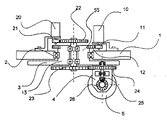
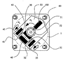
図1および図2は、請求項1,2の発明に関わる実施例の側面図および下側より見た平面図である。車両本体1には、駆動輪操舵用の回転板3を有する操舵軸13が操舵軸回転用軸受2によって鉛直軸周りの回転を自在に支持されている。回転板3には駆動輪支持部材4によって駆動輪5が操舵軸から駆動輪5の転がり方向に距離s、さらに、それと直交する方向、つまり駆動輪5の回転軸と平行な方向にdだけ離間した位置に配置されている。操舵軸駆動用モータ10、及び駆動輪軸駆動用モータ20は共に車両本体1に固定されるように設置される。
【0052】
回転板3は操舵軸駆動用モータ10によって、モータ軸平歯車11、操舵軸が有する平歯車12を介して回転駆動される。また、駆動輪5は駆動輪軸駆動用モータ20によって、モータ軸平歯車21、平歯車22、平歯車23、平歯車24、ベベル歯車25、ベベル歯車26を介して回転駆動される。
【0053】
次に動作について説明する。駆動輪軸駆動用モータ20を停止した状態にて、操舵軸駆動用モータ10を回転駆動すると、回転板3が回転する。このとき、回転板3上に回転支持された平歯車24は遊星歯車の要領で平歯車23を中心として回転運動をするので、この平歯車24は回転板3に対して回転することにより駆動輪5が回転する。
【0054】
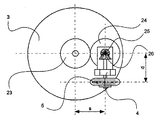
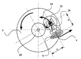
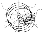
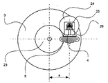
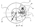
図3,図4に示すように、回転板3を紙面上にて反時計方向に回転させたとき、駆動輪軸駆動用モータ20が回転していないにもかかわらず、駆動輪5は紙面右方向に移動するように回転する。このとき、駆動輪横方向のオフセット距離dを調節することで、操舵軸駆動用モータ10の回転によって生じる駆動輪5の姿勢の変化に対する、速度干渉による駆動輪5の回転によって生じる駆動輪5の床に対する移動量を、距離dを適切な値とすることにより、駆動輪5が操舵軸からsの距離の点、つまり点O'を中心とする半径dの円の円周上を転がるようにすれば、操舵軸の中心点Oも点O'を中心とした半径sの円周上を運動する。
【0055】
これより、前記特開平9-164968号公報に記載された発明の目的とする運動がこの車輪機構においても達成され、かつ駆動輪軸駆動用モータ20を回転させなくとも、駆動輪5の転がりの方向への速度ベクトルは点Oに発生しないので、操舵軸駆動用モータ10と駆動輪軸駆動用モータ20との速度干渉を除去することができる。
【0056】
次に、請求項2の発明に関わり、駆動輪5の転がりの方向、及びオフセット距離dの決定方法について説明する。駆動輪5の転がりの方向は、歯車の構成と操舵軸に対して駆動輪5の配置される方向により決定される。前述のように、図1、2に示す配置例では、回転板3が紙面上にて反時計周りに旋回駆動されたとき、駆動輪5も反時計方向に向きを変えながら紙面右方向に回転、移動する(図4)。このときの重要な関係は、駆動輪5の旋回方向と、その時の駆動輪5の床面に対して移動する方向である。
【0057】
図4における例では、駆動輪5が反時計周りに旋回するときには、駆動輪5は右方向に移動しなければならない。例えばこの回転の方向を逆にするには、平歯車23と平歯車24の間にアイドラーとしての平歯車を挿入すれば良い。
【0058】
また、距離dは、駆動輪の旋回中心を点O'と一致させるように調整する。平歯車23〜26のそれぞれの歯車の有効半径をr23〜r26とすると、この歯車23から車輪5までの減速比G(G>1にて減速)は、
【0059】
【数7】
【0060】
【数8】
【0061】
【数9】
【0062】
【数10】
![]()
式3、4を代入すると、
【0063】
【数11】
【0064】
【数12】
![]()
(数11)と(数12)からθsを消去し、dを求めると、下記(数13)が導出される。
【0065】
【数13】
【0066】
(実施例2)
次に請求項3に関わる全方向移動車両の実施例について、以下に説明する。図6、7は、実施例2の側面図、下側平面図をそれぞれ示す。この実施例は、平歯車23、24と、ベベル歯車25、26の動力伝達経路上の配置を、前記実施例1とは逆にしたものである。この構成により、平歯車を鉛直面内に配置できるばかりでなく、歯車22により駆動される軸を、操舵軸中心から駆動輪5の中心付近の高さまで延長でき、駆動輪5の上部の歯車などを配置する必要がなくなることから、駆動輪5が上下動できる寸法の余裕ができる。
【0067】
この実施例においては、平歯車24、駆動輪5を支持する駆動輪支持用リンク部材7を、操舵軸13に固着される操舵軸接続部材6とは分離して設け、これを平歯車23、およびベベル歯車26の回転軸まわりに鉛直面内の回転を自在にして支持する。さらに、駆動輪支持用リンク部材7の駆動輪5の配置されている側とは反対側の部分と操舵軸13との間に、引張りばね8を渡し、駆動輪5が床面を押す方向に力を発生させるようにする。
【0068】
また、押す形式のばねを使用する際には、駆動輪支持用リンク部材7の駆動輪5が配置されている側の部分と、操舵軸13との間に押しばね9を挿入することにより、駆動輪5の床面方向への力を発生させる。また、上記引張りばね8、押しばね9とダンパを併設することも可能であり、ばね定数、粘性係数を調節することにより、上記構成によるサスペンション機構の振動吸収能力や、床面への接地能力などを変化させることができる。
【0069】
(実施例3)
次に請求項4に関わる実施例の全方向移動車両について説明する。実施例2の全方向移動車両における車輪機構においては、各車輪機構は独立なサスペンションを搭載し、床面の凹凸に対応して、その駆動輪の上下動を行う。このとき、各サスペンション機構に備えられるばねは、その駆動輪にかかる垂直抗力を支え、また、これに比例した変位を伴っている。これより、サスペンション機構のばねの変位を測定することで、その駆動輪に作用している垂直抗力を測定することができる。
【0070】
これは、ばねに図6には図示しない直線的な変位を測定するポテンシオメータなどの簡単なセンサを併設することにより実現できる。車両に搭載される複数の車輪に備えられる複数のセンサから力情報の総和から、車両搭載物を含めた総重量を、また、力分布から重心の位置を推定することが可能となる。
【0071】
(実施例4)
次に請求項5の発明に関わる実施例の全方向移動車両について説明する。実施例3においては、ばねの横にその変位を計測するセンサを取り付けることにより、駆動輪5に作用する垂直抗力を測定したが、センサは駆動輪5と共に回転する部位に取り付けなければならず、配線の問題がある。そこで、図8に示すように、操舵軸中心を貫通する可動子62を設置し、この変位を計測することで、ばねの変位を測定する。
【0072】
可動子62は、ばね61により常に下方向に押付けられるように与力を受けている。また、その変位は車両本体1に固定された直線型ポテンシオメータなどの直線変位計測計60により検出される.可動子62の先端は、サスペンション機構の回転によって上下動の動きが得られるように、図9(a)から(c)に示すような摺動部材63に接触している。図9(a)から(c)に示す例では、駆動輪5が車両本体方向に上昇した場合には、可動子62が上昇し、また、駆動輪5が下降した場合には、可動子62が下降する。
【0073】
(実施例5)
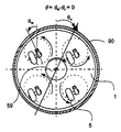
次に請求項6の発明に関わる全方向移動車両の制御方法の実施例について説明する。図10(a),(b)は、この実施例に関わる模式図である。車両には、少なくとも請求項2の発明に関わる駆動ユニットが2ユニット搭載される。図10は、4ユニット搭載の実施例を示す。
【0074】
車両の制御基準点にその原点が仮想的に設置された車両座標系における、第i番めの駆動ユニットの操舵軸中心の位置をxi、yiとして定義する。このとき、車両がx軸方向にvvx、y軸方向にvvyの速度で、旋回運動を伴わない並進運動を行うとき、これを実現するために各駆動ユニットに要求される各軸方向の速度は、それらの位置xi、yiとは無関係で、下記(数14)のように車両速度と同じ速度がそれぞれ要求される。
【0075】
【数14】
【0076】
【数15】
【0077】
【数16】
これを代入すると、Li、θiは消去され、下記(数17)を得る。
【0078】
【数17】
【0079】
【数18】
【0080】
【数19】
ここで、θwiは、図10(a)に示すように、車両基準座標系に対する各駆動輪5の姿勢である。
【0081】
これらから、最終的に操舵軸駆動用、駆動輪軸駆動用の各モータに与える角速度指令値は、下記(数20)のように求められる。この(数20)は(数2)と同一である。
【0082】
【数20】
【0083】
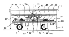
(実施例6)
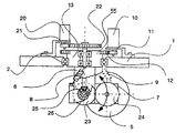
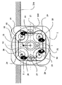
次に、請求項7、8および9の全方向移動車両とその制御方法に関わる実施例について説明する。図11に実施例の上面図を、図12に側面図を示す。駆動セット550には、請求項2における駆動ユニットのモータ10、20を除いた車輪機構としての駆動ユニット55が複数ユニット(図11では4ユニット)設けられ、全ての車輪機構の操舵を行う操舵動力用プーリ19は、駆動セット550に設けられ、全ての駆動輪が同一の方向を向くようにして、ベルト18をもって動力的に結合される。また、駆動輪5を駆動する各駆動輪動力用プーリ29も同様にして、ベルト28をもって動力的に結合される。
【0084】
操舵動力用プーリ19を結合するベルト18は、単一の操舵軸駆動用モータ10によって駆動され、その結果全ての駆動輪5の操舵が同時に行われ、全駆動輪5は常に同方向に向く。また、駆動輪動力用プーリ29を結合するベルト28は、別の単一の駆動輪軸駆動用モータ20によって駆動され、その結果、全駆動輪5は常に同じ角速度にて回転、床面を移動する。これらの車輪機構において支持、駆動される駆動セット550は、上記2つのモータの同期制御によって、あらゆる方向の並進運動を行うことができる。以下にその同期制御の方法を説明する。
【0085】
まず、駆動輪軸駆動用モータ20を駆動すると、平行に保たれた駆動輪5は全て同速度にて回転するので、各駆動ユニットの操舵軸中心には、駆動輪5の転動方向に同じ速度が発生する。一方、操舵軸駆動用モータ10を駆動すると、全駆動輪5は、同時に向きを変えるように動作し、その結果各操舵軸中心に駆動輪5の横方向の速度を発生する。これら駆動輪軸駆動用モータ20によって発生する速度ベクトルと、操舵軸駆動用モータ10によって発生する速度ベクトルは常に互いに直交し、かつそれぞれのモータの速度制御により独立に決定できる。
【0086】
駆動セット550はこれら各操舵軸中心における速度ベクトルの合成速度ベクトルにより並進運動を行う。よって、要求される方向のベクトル(つまり車両の動作指令の速度ベクトル)を駆動輪5の床面に対する姿勢に応じて、瞬間瞬間における駆動輪5の方向と、それに直交する方向に分解し、それぞれを各モータ20、10への速度指令値として連続的、あるいは極めて短時間の繰り返し操作にて制御することで、動作指令に対応した合成速度ベクトルを発生させ、床面に対して任意な方向への全方向移動動作を実現することができる。車両本体1の動作指令の並進速度ベクトルから、車輪軸駆動用モータ20、操舵軸駆動用モータ10への速度分解の式を下記(数21)に示す。
【0087】
【数21】
【0088】
ここで、前述のように、駆動セット550はいかなる並進方向の動作によっても鉛直軸まわりに旋回運動しないことから、旋回用モータ50の速度制御においては、車両の並進運動を考慮する必要はなく、車両本体1の旋回運動が要求されるときにのみ、回転動作し、これを制御すれば良い。このことより、車両全体として並進運動と旋回運動が非干渉化された制御が可能となる。以上により、並進の制御式と組み合わせることで、車両全体の制御式は下記(数22)のように求められる。(数22)は、(数3)と同一である。
【0089】
【数22】
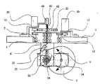
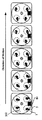
次に、請求項9の全方向移動車両の制御方法に関わる実施例について、さらに説明する。図12は実施例7に関わる側面図を示す。
【0090】
駆動セット550には、駆動輪5を備える複数の駆動ユニットと、3つのモータ10、20、50、およびこれらを結合する動力伝達機構であるベルト18、19、および旋回ステージ53を搭載する。車両本体1は、旋回用モータ50によって回転駆動される歯車58、旋回ステージ53を介して、車両中心を通る鉛直軸周りに旋回する。絶対角度検出型エンコーダ70は、その回転中心を車両本体1の回転中心と同一になるようにして車両本体1に直接固定される。また、その測定軸71は、操舵駆動用モータ10によって駆動されるベルト18によって、プーリ19を介して回転される。これより、絶対角度検出型エンコーダ70は、駆動セット550の状態にはよらず、車両本体1に対する駆動輪5の向きを計測することが可能となる。
【0091】
(実施例8)
次に、請求項10の全方向移動車両の制御方法に関わる実施例について、図13により説明する。請求項9の全方向移動車両の制御方法の実現に際しては、車両本体1に対する駆動輪5の相対角度を計測するために、絶対角度検出型エンコーダ、または、ポテンシオメータを用いることが一般的である。近年では、コンピュータとの入出力が容易であること、ノイズに強いシステムを構築できること、などの理由から、デジタル出力のエンコーダの方が多く用いられる傾向にある。この発明の車両制御システムにおいては、この角度検出値に基づいて、車両の速度分解の計算が行われることから、高精度の角度検出が要求される。
【0092】
しかし、絶対角度検出型エンコーダのうち、機械的に高分解能のスリットを用いているものは非常に高価であり、また、電池、あるいは微少電力によるバックアップにて高分解能を実現するものは、保守の点から好ましくない。そこで、比較的低分解能の絶対角度検出型エンコーダと、モータのシャフトに備えられた積算型エンコーダを用いて、高分解能の絶対角度検出を行う.これまでも、低分解能の絶対角度検出型エンコーダと、積算型エンコーダを併用した高分解能角度検出は存在し、積算型エンコーダの積算カウンタの値を、絶対角度検出型エンコーダの最小分解能以下の測定値とみなし、高分解能を実現していた。
【0093】
例えば、8ビットの絶対角度検出型エンコーダと、4ビットの積算カウンタを用いたとすると、8ビットを上位、4ビットを下位とみなすことで、結果的に12ビットの分解能を実現することが可能である.しかし、これは、ひとつのアクチュエータによって駆動される軸の角度計測についてのみに適用が可能なものである。
【0094】
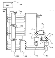
本システムにおいては、車両本体1と駆動輪5の相対角度を測定することが目的であるが、この角度は、操舵軸駆動用モータ10、旋回用モータ50のいずれか、あるいは両方を回転駆動することで変化する。請求項10の発明の制御方法を実現するには、図13に示す構成が採用される。本構成においては、旋回用モータ50により絶対角度検出型エンコーダ70本体を回転させ、操舵軸駆動用モータ10によりその測定軸71を回転させていることに相当する。つまり、二つのモータによって一つの軸が駆動される。
【0095】
このことから、上記の従来の方法を適用することはできない。二つのモータ10、50に取り付けられた積算型エンコーダ81、82は偏差カウンタ100の正、負の2つの入力に信号が接続される.また、絶対角度検出型エンコーダ70の最下位ビットは偏差カウンタ100のリセットを行うように接続される。演算部(CPU)104の保持信号により、各4ビットずつ割り当てられた4ビット信号保持装置101〜103により、その瞬間の各ビットの状態を保持することで、絶対角度検出型エンコーダ70、および偏差カウンタ100により計測された値を同期して取り込むことができる。
【0096】
次にこの動作について説明する。図14(a)に示すように、操舵軸駆動用モータ10が駆動輪5を反時計方向に操舵するとき、あるいは同図(b)に示すように旋回用モータ50が車両外郭部90を負方向に回転するとき、さらにこの両方が同時に起こる場合において、車両外郭部90と、駆動輪5の相対角度は増加するように変化する。よって、操舵軸駆動用モータ10のエンコーダ81は偏差カウンタ100の正の入力に、旋回用モータ50のエンコーダ82は偏差カウンタ100の負の入力に接続する。
【0097】
これにより、駆動輪5が反時計方向にわずかに操舵されたときには、偏差カウンタ100の出力は正の入力と等しくなり、これが車両本体1と駆動輪5の相対角度となる。また、車両本体1が時計方向にわずかに回転されたときには、偏差カウンタ100の出力は車両本体1の駆動角度の逆符号の角度を示し、つまりこの場合正の値が出力され、このときにも出力は、車両本体1と駆動輪5の相対角度に等しくなる。また、例えば図15に示すように、駆動輪5が反時計方向にある角度わずかに回転し、車両本体1も同方向にそれと同じ角度回転されたとすると、偏差カウンタ内部にて、正の入力と負の入力の加減算を行う結果、その出力は零となり、実際の車両本体1と駆動輪5の相対角度、つまり零、と一致することとなる。
【0098】
また、絶対角度検出型エンコーダ70の最下位ビットが変化するほど大きく相対角度が変化した場合には、このビットの変化により、偏差カウンタはリセットされるので、最下位ビットが変化した瞬間からの角度変化を再び記憶することとなる。つまり、偏差カウンタ100は絶対角度エンコーダ70の最下位ビットの分解能以下の角度を、ふたつの積算型エンコーダ81、82からのパルスを用いて常に計測することができる。図13において、CPU104は、絶対角度検出型エンコーダ70からの上位8ビットと、偏差カウンタ100からの下位4ビットを情報保持装置101から104を用いて同時に保持し、これを取り込むことで、ある瞬間における高分解能な角度を検出することができる。
【0099】
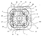
(実施例9)
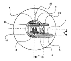
次に、請求項11の全方向移動車両に関わる実施例について、図16により説明する。請求項7、8の発明に関わる実施例(図11、図12)においては、駆動輪軸駆動用モータ20と、操舵軸駆動用モータ10の動作を速度的に非干渉化したことより、複数の駆動輪を搭載した車両において、横方向への偏りの形態の異なる駆動ユニット(右方向の横にオフセットしているか、左方向の横にオフセットしているか)が混在していても、これらを共通のモータにより駆動することが可能である。
【0100】
よって、車両上の駆動輪の位置やその他の要因によって適した駆動ユニットの形態を選択することができる。ここでは、駆動輪軸駆動用モータ20と操舵軸駆動用モータ10との間のトルク干渉を除去、あるいは緩和するために、異なる形態の駆動ユニットを混在して配置する方法について説明する。
【0101】
図16には、この実施例の平面図を示す。例えば、車両全体が紙面上方に移動し、駆動輪5が段差を乗上げようと、段差250の縁に駆動輪5の一部が接触した状態を考える。このとき、駆動輪5が段差250の縁に接触する瞬間に、車両からの慣性力を受ける結果、操舵軸まわりには大きなトルクが作用する。このとき、左前方の駆動ユニットにおいては操舵軸を反時計周り方向に回転させようとするトルクが作用し、また、右前方の駆動ユニットにおいては時計周り方向のトルクが操舵軸に作用する。
【0102】
しかし、これらの操舵軸駆動用プーリ19はベルト18にて結合されているので、上述の操舵軸にかかるトルクはベルト18を互いに引き合うように作用し、駆動セット550に作用する内力として消去され、操舵軸駆動用モータ10まで伝達しない。そのため、駆動輪5が2輪同時に段差に衝突する際には、段差に衝突した影響による外乱トルクはほとんど除去される。
【0103】
車両が全方向へ移動する場合には、いずれの方向へ向かう際にも進行方向前方の駆動輪はその形態が左右異なることが望ましい。これを実現するためには、図16に示すように、隣接する駆動ユニットにおける前記駆動輪と操舵軸との相対位置関係を逆に配設する。つまり、一方の対角に位置するふたつの車輪が同様の形態の駆動ユニットとなり、また、他の対角に位置するふたつの駆動ユニットはこれと逆の形態をとる。
【0104】
(実施例10)
次に、請求項12の全方向移動車両の制御方法に関わる実施例について、図17により説明する。請求項7〜11のいずれかの全方向移動車両または制御方法においては、車両が理想的な動作を行っている際(つまり完全な平面上において駆動輪5と床との間の滑りが生じない状態)には駆動セット550は回転運動を行わないということがひとつの特徴である。図17に駆動輪5の横方向へ移動する場合の動作例を示す。これから、車両本体1が鉛直軸まわりに回転運動をした場合には、駆動輪に滑りが生じた、即ち理想的な走行状態ではない状況であると判断することができる。
【0105】
これより、駆動セット550にジャイロスコープなどの回転計測器84を設置し、その鉛直軸周りの回転を計測することで平坦地における駆動輪5と床の間の滑りを検出することができる。またこの場合、駆動セット550の回転はそれほど早くなく、上記のような状況の場合のみ起こることから、従来の車両に搭載される回転計測器よりも測定レンジの狭い、高分解能、高感度なセンサを使用できるので、角度検出精度が向上し、走行精度も向上させることができる。
【0106】
(実施例11)
次に、請求項13の全方向移動車両の制御方法に関わる実施例について、図18により説明する。車両の姿勢誤差は、走行距離が長くなるにつれ位置誤差が増大することから、走行精度の影響が非常に大きく、これを高精度に制御することは重要な問題である。
【0107】
請求項7ないし12のいずれかの全方向移動車両またはその制御方法においては、車両の運動状態(旋回運動や並進運動を行っているか)にかかわらず、駆動セット550に搭載された回転計測器84は、駆動セット550の旋回のみを検出する。前述の検討から、駆動セット550は、駆動輪と床との間の滑りがあったときのみにその姿勢を変化させることから、回転計測器84から出力があった場合には駆動輪に滑りが生じ、その滑りの大きさが駆動セット550の回転速度に比例するものとして捕らえることができる。
【0108】
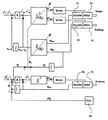
図18において、記号右肩の*印は、その変数の目標値であることを示す。車両の操舵軸駆動用モータ10、駆動輪軸駆動用モータ20にそれぞれ取り付けられたエンコーダ83、81から送られるモータの角度の情報に基づき、車両の運動学モデルであるJ(θw)を計算することにより車両の実際位置xv、yv、および実際速度vvx、vvyの予想値を得る。この実際位置の予想値は、図示しない上位制御装置、または、図示しない操作装置から車両に指令される並進方向の位置目標値xv*、yv*と比較され位置誤差が検出される。
【0109】
さらにその位置誤差は速度目標値vvx*、vvy*として見なされ、実際速度vvx、vvyと比較される.これらフィードバック制御の計算により最終的に得られる速度誤差に基づいて車両の逆運動学モデルであるJ-1(θw)を計算することにより操舵軸駆動用モータ10、駆動輪軸駆動用モータ20の目標回転角速度ωms*、ωmw*を決定する.このモータの目標回転角速度に従って操舵軸駆動用モータ10、駆動輪軸駆動用モータ20が制御される。
【0110】
また、車両の姿勢は、車両旋回用モータ50によってのみ制御される。車両の姿勢の実際値の予想値は、駆動セット550の姿勢の初期値(図はこれを零に設定した場合である)に車両旋回用モータ50の回転角度を加算することにより得ることができる。この実際姿勢の予想値は、車両の並進方向の位置と同様、図示しない上位制御装置、または図示しない操作装置から指令される姿勢目標値θv*と比較され、姿勢誤差が検出される。さらにその姿勢誤差は車両旋回用モータ50に搭載されるエンコーダ82によって計測される実際角速度ωvと比較され、その結果に基づき、車両の旋回の逆運動学モデルJr -1を計算することにより車両旋回用モータ50の目標回転角速度ωmr*が決定される.このモータの目標回転角速度に従って車両旋回用モータ20が制御される。
【0111】
以上のように、操舵軸駆動用モータ10と駆動輪軸駆動用モータ20は車両の並進方向の動作を制御するために組みとなって制御、駆動され、また、車両旋回用モータ50は車両本体の姿勢を制御するために単独にて制御、駆動される。ここで、並進運動の計算に使用される運動学モデルJ(θw)、および逆運動学モデルJ-1(θw)は、車両本体に対する駆動輪の方向θwの関数となっており、この駆動輪の方向θwが不正確であった場合には、床面に対する目標軌道の方向と、車両の実際の走行方向に角度誤差が発生することから、この車両本体に対する駆動輪の方向θwを正確に把握する必要がある。
【0112】
ここで、この駆動輪の方向θwは、車両本体の姿勢θvから駆動セット550に対する駆動輪の角度θsを減じることによって得ることができる。このうち、駆動セット550に対する駆動輪の角度θsの変化は操舵軸駆動用モータ10に搭載されたエンコーダ83により正確に知ることができる。これに対して、車両本体の姿勢θvは、駆動セット550の初期姿勢に車両旋回用モータの回転θsを加算することで算出されるので、駆動セット550の実際の姿勢が初期姿勢に対してずれてしまった場合には、実際の値とは異なることになる。
【0113】
一方、駆動セット550が、初期姿勢からずれる場合に、この姿勢のずれのみを回転計測器84を用いて計測可能であることから、その出力Δθvを姿勢の予想値に単純に加えあわせることで、駆動セット550の初期姿勢からの誤差姿勢、つまり駆動セット550の床に対する姿勢Δθvを得ることができ、これから車両本体の姿勢θv、車両本体に対する駆動輪の角度θwすべてを補正することが可能となる。このように正確に補正された車両本体に対する駆動輪の角度θwを使用して、並進運動の計算に使用される運動学モデルJ(θw)、および逆運動学モデルJ-1(θw)を随時最新のものに更新(図18において点線にて表記)することによって、旋回運動のみならず、並進運動も床面に対して正確に制御、あるいは実際位置を予想することが可能となる。
【0114】
以上の説明のように、従来のシステムのような駆動輪の回転、操舵角などの様々な計測値から車両の誤差を算出するといった計算処理が不要となり、極めて短時間、かつ容易に誤差の補正処理を完了することができる。
【0115】
【発明の効果】
以上詳述したように、上記一連の発明によれば、車両を駆動するそれぞれのアクチュエータ間の速度干渉を除去することにより、制御系を簡素化し、さらには駆動輪軸駆動用モータ及び車両旋回駆動用モータの小容量化を図ることができる。さらに、操舵軸にかかる外乱トルクを操舵軸駆動用アクチュエータにまで伝えることなく、操舵軸用のアクチュエータの更なる小容量化を図ることができる。
【0116】
総じて、制御系、駆動系の非干渉化、簡単化、およびアクチュエータの小容量化、省電力駆動などを行うことにより、低コスト、高信頼性、高精度走行能力を有する実用的なホロノミック全方向移動車両を提供することができる。
【図面の簡単な説明】
【図1】請求項1,2の発明に関わる実施例の側面図
【図2】請求項1,2の発明に関わる実施例の平面図
【図3】請求項1,2の発明の動作原理を概念的に説明するための図
【図4】請求項1,2の発明の動作原理を概念的に説明するための図
【図5】請求項2の発明の計算式を説明するための図
【図6】請求項3,4の発明に関わる実施例の側面図
【図7】請求項3,4の発明に関わる実施例の平面図
【図8】請求項5の発明に関わる実施例の側面図
【図9】請求項5の発明に関わる実施例の動作説明図
【図10】請求項6の発明に関わる実施例の速度ベクトル図
【図11】請求項7,8,9の発明に関わる実施例の平面図
【図12】請求項7,8,9の発明に関わる実施例の側面図
【図13】請求項10の発明に関わる制御方法を説明するためのシステム構成図
【図14】請求項10の発明に関わる実施例の動作説明図
【図15】請求項10の発明に関わる実施例の動作説明図
【図16】請求項11の発明に関わる実施例の平面図
【図17】請求項12の発明に関わる実施例の動作説明図
【図18】請求項13の発明に関わる制御方法を説明するためのシステム構成図
【図19】従来のキャスタ型駆動輪機構の一例の側面図
【図20】従来のキャスタ型駆動輪機構の一例の平面図
【図21】従来のキャスタ型駆動輪機構における速度ベクトル図
【図22】従来のキャスタ型駆動輪機構の動作説明図
【図23】従来の双輪キャスタ型駆動輪機構を用いた車両の模式図
【図24】従来の双輪キャスタ型駆動輪機構を用いた車両の動作例を示す図
【符号の説明】
1:車両本体、2:操舵軸回転用軸受、3:回転板、4:駆動輪支持部材、5:駆動輪、6:操舵軸接続部材、7:駆動輪支持用リンク部材、8:引張りばね、9:押しばね、10:操舵軸駆動用モータ、11,21,51:モータ軸平歯車、12,22,23,24:平歯車、18,28:ベルト、19:操舵動力用プーリ、20:駆動輪軸駆動用モータ、25,26:ベベル歯車、29:駆動輪動力用プーリ、50:旋回用モータ、52:歯車、53:旋回ステージ、55:駆動ユニット、70:絶対角度検出型エンコーダ、81,82,83:積算型エンコーダ、84:回転計測器、100:偏差カウンタ、101,102,103:4ビット信号保持装置、104:CPU、550:駆動セット。[0001]
BACKGROUND OF THE INVENTION
When changing the turning speed or traveling direction of a vehicle, or when starting running or turning from a stopped state, the present invention provides a waiting time for vehicle preparation such as changing the direction of wheels. It is not necessary to move immediately from any vehicle posture in any direction, start turning, or change the direction of movement, turning speed even during the movement, or academically holonomic The present invention relates to an omnidirectional vehicle that is expressed as having an appropriate movement characteristic and a control method thereof.
[0002]
[Prior art]
An omnidirectional vehicle that moves on a plane is a vehicle that can control a total of three degrees of freedom: the moving speed of the vehicle in the traveling direction and the lateral direction, and the angular velocity around the vertical axis of the vehicle, that is, the attitude change of the vehicle. There are many inventions known in this regard. These omnidirectional vehicles are roughly classified into the following two types. The first type of vehicle is a vehicle called a vehicle that is academically nonholonomic.
[0003]
In this first type of vehicle, when changing the traveling direction of the vehicle or moving to a turning operation, for example, a standby operation for changing settings of some mechanisms inside the vehicle, such as changing the direction of each wheel. , And time is required. This vehicle is a mechanism having two degrees of freedom, and the three degrees of freedom of the vehicle cannot be controlled simultaneously and independently, and two of the three degrees of freedom of the vehicle are selected in order. Is finally considered to control the three degrees of freedom of the vehicle.
[0004]
Therefore, for example, it is not possible to follow a right-angled route without waiting time, and it is necessary to travel in an arc shape, or to temporarily stop at a corner and start traveling again after waiting time. Vehicles classified as the first type include all-wheel steering type omnidirectional vehicles.
[0005]
On the other hand, the second type of vehicle is academically referred to as a holonomic vehicle, and this type of vehicle does not require any change in the setting of the internal mechanism of the vehicle. The main feature is that movement and turning in all directions can be started immediately from the position, and the three degrees of freedom of the vehicle can be controlled simultaneously and independently. Vehicles classified in this way include omnidirectional vehicles that use spherical wheels, or omnidirectional vehicles that use special wheels with many freely rotating rollers around large wheels. is there.
[0006]
Further, the vehicle described in Japanese Patent Laid-Open No. 9-164968 and proposed by the same applicant is also classified as a second type of omnidirectional vehicle, which is a wheel of a wheel in the form of a caster. Both the shaft and the steering shaft are independently driven by an actuator, and two or more drive wheels are provided to realize the omnidirectional movement of the predetermined three degrees of freedom. According to the wheel mechanism according to the invention described in Japanese Patent Laid-Open No. 9-164968, a normal type of tire (such as a rubber tire or a pneumatic tire) can be mounted, thereby realizing a smooth and agile omnidirectional movement operation. Is possible.
[0007]
[Problems to be solved by the invention]
However, the wheel mechanism used in the invention described in the above-mentioned JP-A-9-164968 has a steering shaft that continuously rotates an infinite number of times. The two actuators for driving the steering shaft are both installed on the vehicle body, and the rotational motion is transmitted via a transmission mechanism such as a gear. Therefore, there is a problem that speed interference occurs between the two actuators.
[0008]
That is, even if only the steering shaft actuator is driven so as to change the direction of the wheel while the wheel driving actuator is stopped, a phenomenon occurs in which both the steering and the wheel rotate. On the other hand, when the wheel drive actuator is driven while the steering shaft drive actuator is stopped, only the wheel rotates. From this, one-way speed interference from the steering shaft driving actuator to the wheel driving actuator occurs.
[0009]
In the above-described invention, in order to eliminate this speed interference, it is necessary to perform motion control by adding a rotational speed of a predetermined ratio of the rotational speed of the steering shaft to the wheel shaft actuator in advance. In other words, in order to eliminate this speed interference, it is necessary to mount an actuator that drives faster than the maximum rotational speed actually required for the wheel for driving the wheel.
[0010]
Furthermore, the torque for driving the wheel acts on a part of the transmission mechanism of the steering shaft, for example, one gear as a fulcrum, so that it is transmitted to the wheel regardless of whether the steering shaft is rotating or stopped. Therefore, there is a problem that the steering shaft driving actuator must generate enough torque to support the generated torque. This is because a sudden torque is applied to the steering shaft at the time of acceleration / deceleration or when the level difference is raised or lowered, which is nothing but a disturbance for the steering shaft actuator.
[0011]
When a speed error occurs in the steering shaft due to the torque from the wheel actuator, the traveling direction of the vehicle is shifted, resulting in a traveling error of the vehicle. The generation of this error is important. It was a problem.
[0012]
In the invention described in Japanese Patent Laid-Open No. 9-164968, there is also proposed an omnidirectional vehicle in which an actuator for turning the vehicle body is added to a drive unit in the form of a twin-wheel caster. This vehicle can control the translational and rotational motion of the vehicle by two drive wheels and three actuators that drive the steering shaft of the drive unit. The vehicle is over-constrained using a plurality of single-wheel casters ( (A state where the actuator is controlled by a larger number of actuators than the degree of freedom).
[0013]
In this dual-wheel caster configuration, the steering shaft actuator is installed on the drive unit, and even when the vehicle does not turn (e.g., simple translational motion), the influence of the direction change of the drive unit. In order to correct this, it is necessary to drive the vehicle body in the direction opposite to the rotation of the drive unit, and therefore it is necessary to consider the motion in the translation direction in the control calculation of the turning shaft actuator of the vehicle body. This not only complicates the control system, but also requires the mounting of a turning axis actuator for the vehicle body having a larger capacity than necessary.
[0014]
In other words, the above-mentioned two problems are that the interference between a plurality of actuators that drive the vehicle not only degrades the running accuracy of the vehicle, but also complicates the control system and increases the capacity of the actuator. It will be.
[0015]
The above problems will be described in detail below with reference to the drawings. FIG. 19 shows a side view and FIG. 20 shows a bottom view of a drive wheel mechanism as an example of a conventional caster type. This example is a partial modification of the embodiment described in JP-A-9-164968.
[0016]
19 and 20, a
[0017]
As shown in FIG. 21, the operation purpose of this drive wheel in Japanese Patent Laid-Open No. 9-164968 is to set the speed in an arbitrary direction in the horizontal plane at the center of the steering shaft, that is, the center position of the
[0018]
Here, the above operation is performed when the
As shown in FIG. 22, consider a case where the steering
[0019]
As the
[0020]
The ratio of the rotation angle of the
[0021]
In the implementation of the invention of Japanese Patent Laid-Open No. 9-164968, the means for removing the speed interference is indispensable in order to achieve the operation shown in FIG. For this reason, the wheel
[0022]
Further, for example, when considering a state in which the
[0023]
FIG. 23 shows a configuration related to a different embodiment described in JP-A-9-164968. In this configuration, a holonomic omnidirectional movement is achieved by three actuators by using a twin-wheel caster type drive unit. This is because the
[0024]
At this time, although the posture of the vehicle
[0025]
As a result, the maximum speed in consideration of the rotation of the
[0026]
The present invention has been made to solve the above-described problems of the conventional omnidirectional vehicle, and an object of the present invention is to eliminate the speed interference between the actuators that drive the vehicle, thereby providing a control system. Is to further reduce the capacity of the driving wheel shaft driving motor and the vehicle turning driving motor.
[0027]
Furthermore, it is to further reduce the capacity of the steering shaft actuator without transmitting the disturbance torque applied to the steering shaft to the steering shaft driving actuator.
[0028]
As a result, the omnidirectional mobile vehicle itself is reduced in size, weight and price, energy consumption is reduced, the vehicle is driven for a long time such as an autonomous vehicle, or the battery is reduced in size and weight.
[0029]
[Means for Solving the Problems]
In order to solve the above-described problem, the invention of
[0030]
According to a second aspect of the present invention, in the omnidirectional vehicle according to the first aspect, the second power transmission means is arranged around a vertical axis independently of the steering shaft by the driving wheel shaft driving actuator. And a power transmission unit B connected to the power transmission unit A and capable of moving about the vertical axis together with the steering shaft. The reduction ratio of the power transmission unit B is defined as G. It is assumed that the predetermined distance (d) satisfies the relationship expressed by the following equation (Equation 4), where G> 1 and deceleration, where r is the radius of the drive wheel.
[0031]
[Expression 4]
[0032]
According to a third aspect of the present invention, in the omnidirectional vehicle according to the second aspect, the drive wheel support member includes a steering shaft connection member that is connected and fixed to a steering shaft, and a shaft connected to the steering shaft connection member. A drive wheel support link member that is pivotally supported on the same rotation axis as the rotation axis of the supported gear and is rotatably supported in a vertical plane, and that supports the drive wheel. A power transmission part B that can move around the vertical axis together with the shaft is connected to the gear, and is replaced with a power transmission part b that consists of a drive wheel gear that can move around the horizontal axis together with the steering shaft. It is assumed that vibration absorbing means for absorbing vibration during driving of the driving wheel on the floor surface is provided between the driving wheel supporting link member.
[0033]
According to the above configuration, even if there is a slight unevenness on the floor surface, the driving wheel can be kept in a grounded state. Therefore, particularly when a plurality of driving wheels are provided, sufficient vehicle driving force and stability can be obtained. It can be held, and the running performance is improved.
[0034]
According to a fourth aspect of the present invention, in the omnidirectional vehicle according to the third aspect, the vibration absorbing means includes a spring, and a linear position such as a linear drive type potentiometer is provided in parallel with the spring. A vehicle weight measuring means capable of measuring the vertical drag acting on the driving wheel by measuring the displacement of the spring by providing a detector and measuring the weight of the entire vehicle including the load or the position of the center of gravity. It shall be provided. With the above configuration, by measuring the displacement of the spring of the suspension mounted on each drive wheel mechanism, it is possible to estimate the total weight of the vehicle, the position of the center of gravity, etc., and to further improve the stability of the vehicle.
[0035]
According to a fifth aspect of the present invention, in the omnidirectional vehicle according to the third aspect, the mover that moves up and down according to the displacement of the vibration absorbing means that rotates together with the steering shaft passes through the center of the steering shaft. And a linear position detector such as a potentiometer installed in a portion that does not rotate due to the steering operation, and the vibration is absorbed by measuring the displacement of the mover with the linear position detector. It is assumed that there is provided a vehicle weight measurement means capable of measuring the displacement of the means and thereby measuring the weight of the entire vehicle including the load or the position of the center of gravity. As described above, since the sensor for measuring the displacement of the suspension spring can be installed in the vehicle body, it is not necessary to pass wiring to the rotating part, and the reliability of the apparatus can be improved.
[0036]
According to a sixth aspect of the present invention, there is provided a control method for an omnidirectional vehicle according to any one of the first to fifth aspects, wherein the vehicle main body includes two or more drive units, and the vehicle reference point Using the position (coordinates) and attitude information of the steering shaft of each drive unit with respect to the virtually installed vehicle reference coordinate system, the steering shaft drive actuator and the drive wheel shaft in each drive unit according to the following equation (Equation 5) The rotational angular velocity of the driving actuator is controlled.
[0037]
[Equation 5]
[0038]
Next, according to the invention of
[0039]
According to an eighth aspect of the invention, there is provided the omnidirectional vehicle control method according to the seventh aspect, wherein the rotational angular velocities of the drive wheel shaft drive actuator, the steering shaft drive actuator, and the vehicle body rotation drive actuator are determined. By controlling based on the following equation (Equation 6), the speed and direction of the drive unit and the vehicle body in the translation direction are controlled, and the direction of the vehicle body is controlled.
[0040]
[Formula 6]
[0041]
Next, the invention according to
[0042]
The invention according to
[0043]
According to the above method, one absolute angle detection type encoder having a relatively low resolution is installed for one axis driven by two actuators, and this is performed by an integrating type encoder attached to two actuators. By correcting the hardware, highly accurate angle detection can be realized by an inexpensive sensor without increasing the software burden.
[0044]
Next, the invention according to
[0045]
According to the above configuration, the disturbance torque from the floor and the step is eliminated or reduced by the power transmission mechanism, and the influence on the actuator is reduced, so that the capacity of the actuator can be reduced.
[0046]
According to a twelfth aspect of the present invention, in the control method for an omnidirectional vehicle according to any one of the eighth to tenth aspects, a sensor for detecting rotation around a vertical axis such as a gyroscope is installed in the drive set. Then, slip between the drive wheel and the floor is detected by the output of the sensor, and the relative angle measurement value of the direction of the drive wheel with respect to the vehicle body is corrected by the slip detection value.
[0047]
According to the above control method, it becomes possible to detect only the posture error of the vehicle, and the vehicle posture recognition algorithm becomes extremely simple. Furthermore, a low-range, high-sensitivity rotation meter can be mounted, and measurement and control can be performed with higher accuracy than conventional similar systems.
[0048]
According to a thirteenth aspect of the invention, in the control method for an omnidirectional vehicle according to any one of the sixth, eighth, ninth, tenth, and twelfth aspects, the vehicle body is rotated around a vertical axis such as a gyroscope. By installing a sensor to detect, and adding the measured value of the rotation angle from this sensor to the vehicle body posture data recognized by the vehicle control device, the vehicle body posture recognition error is corrected. And As described above, since the vehicle attitude value, which is a basic parameter of the vehicle control algorithm, can be updated instantaneously, not only can the burden on the control system be reduced, but also the traveling accuracy of the vehicle can be improved.
[0049]
As described above, according to the series of inventions, the control system, the drive system are made non-interactive, simplified, the actuator is reduced in capacity, the power saving drive, etc., so that the low cost, high reliability, and high accuracy driving ability are achieved. A practical holonomic omnidirectional vehicle can be provided.
[0050]
DETAILED DESCRIPTION OF THE INVENTION
Embodiments of the present invention will be described below with reference to the drawings.
[0051]
(Example 1)
FIG. 1 and FIG. 2 are a side view and a plan view as seen from below of an embodiment relating to the inventions of
[0052]
The
[0053]
Next, the operation will be described. When the steering
[0054]
As shown in FIGS. 3 and 4, when the
[0055]
As a result, the intended motion of the invention described in Japanese Patent Laid-Open No. 9-164968 can be achieved also in this wheel mechanism, and the direction of rolling of the
[0056]
Next, a method for determining the rolling direction of the
[0057]
In the example in FIG. 4, when the
[0058]
The distance d is adjusted so that the turning center of the drive wheel coincides with the point O ′. The effective radius of each of the spur gears 23 to 26 is expressed as r.twenty three~ R26Then, the reduction ratio G (deceleration when G> 1) from the
[0059]
[Expression 7]
[0060]
[Equation 8]
[0061]
[Equation 9]
[0062]
[Expression 10]
![]()
Substituting
[0063]
## EQU11 ##
[0064]
[Expression 12]
![]()
From (Equation 11) and (Equation 12), θsWhen d is obtained, the following (Equation 13) is derived.
[0065]
[Formula 13]
[0066]
(Example 2)
Next, an embodiment of the omnidirectional vehicle according to
[0067]
In this embodiment, the
[0068]
Further, when using a push-type spring, by inserting the
[0069]
(Example 3)
Next, an omnidirectional vehicle according to an embodiment relating to claim 4 will be described. In the wheel mechanism in the omnidirectional vehicle of the second embodiment, each wheel mechanism is equipped with an independent suspension, and the drive wheel moves up and down in accordance with the unevenness of the floor surface. At this time, the spring provided in each suspension mechanism supports the vertical drag applied to the drive wheel, and is accompanied by a displacement proportional to the vertical drag. From this, by measuring the displacement of the spring of the suspension mechanism, the normal force acting on the drive wheel can be measured.
[0070]
This can be realized by providing a simple sensor such as a potentiometer for measuring a linear displacement (not shown in FIG. 6) on the spring. It is possible to estimate the total weight including vehicle-mounted items from the total force information from a plurality of sensors provided on a plurality of wheels mounted on the vehicle, and the position of the center of gravity from the force distribution.
[0071]
(Example 4)
Next, an omnidirectional vehicle according to an embodiment relating to the invention of
[0072]
The
[0073]
(Example 5)
Next, an embodiment of a method for controlling an omnidirectional vehicle according to the invention of
[0074]
The position of the steering axis center of the i-th drive unit in the vehicle coordinate system in which the origin is virtually installed at the control reference point of the vehicle xi, YiDefine as At this time, the vehicle moves in the x-axis directionvx, V in the y-axis directionvyIn order to achieve this, the axial speed required for each drive unit to achieve this is the position xi, YiRegardless of the vehicle speed, the same vehicle speed as the following (Equation 14) is required.
[0075]
[Expression 14]
[0076]
[Expression 15]
[0077]
[Expression 16]
Substituting this, Li, ΘiIs deleted, and the following (Expression 17) is obtained.
[0078]
[Expression 17]
[0079]
[Formula 18]
[0080]
[Equation 19]
Where θwiIs the posture of each
[0081]
From these, the angular velocity command value finally given to each motor for driving the steering shaft and driving wheel shaft is obtained as shown in the following (Equation 20). This (Equation 20) is the same as (Equation 2).
[0082]
[Expression 20]
[0083]
(Example 6)
Next, an embodiment relating to an omnidirectional vehicle according to
[0084]
The
[0085]
First, when the drive wheel
[0086]
The drive set 550 performs a translational motion based on a combined velocity vector of the velocity vectors at the centers of these steering axes. Therefore, the vector of the required direction (that is, the speed vector of the vehicle operation command) is decomposed into the direction of the
[0087]
[Expression 21]
[0088]
Here, as described above, since the drive set 550 does not turn around the vertical axis by any translational operation, it is not necessary to consider the translational movement of the vehicle in the speed control of the turning
[0089]
[Expression 22]
Next, an embodiment related to the omnidirectional vehicle control method of
[0090]
The drive set 550 is equipped with a plurality of drive units including the
[0091]
(Example 8)
Next, an embodiment relating to the omnidirectional vehicle control method of
[0092]
However, absolute angle detection encoders that use mechanically high-resolution slits are very expensive, and those that achieve high resolution with a battery or a small power backup are maintenance-friendly. It is not preferable from the point. Therefore, high-resolution absolute angle detection is performed using a relatively low-resolution absolute angle detection encoder and an integrating encoder provided on the motor shaft. Up to now, there is a high-resolution angle detection that uses an absolute angle detection encoder with a low resolution and an integration encoder together. As a result, high resolution was achieved.
[0093]
For example, assuming that an 8-bit absolute angle detection type encoder and a 4-bit integration counter are used, it is possible to achieve a resolution of 12 bits as a result by regarding 8 bits as upper and 4 bits as lower. is there. However, this can be applied only to the angle measurement of the shaft driven by one actuator.
[0094]
The purpose of this system is to measure the relative angle between the vehicle
[0095]
For this reason, the above conventional method cannot be applied. The integrating
[0096]
Next, this operation will be described. As shown in FIG. 14A, when the steering
[0097]
Thus, when the
[0098]
In addition, when the relative angle changes greatly as the least significant bit of the absolute
[0099]
Example 9
Next, an embodiment relating to an omnidirectional vehicle according to claim 11 will be described with reference to FIG. In the embodiments (FIGS. 11 and 12) relating to the inventions of
[0100]
Therefore, a suitable drive unit form can be selected depending on the position of the drive wheel on the vehicle and other factors. Here, in order to remove or alleviate torque interference between the drive wheel
[0101]
FIG. 16 shows a plan view of this embodiment. For example, let us consider a state in which a part of the
[0102]
However, since these steering
[0103]
When the vehicle moves in all directions, it is desirable that the driving wheels ahead in the traveling direction have different forms on the left and right sides in any direction. In order to realize this, as shown in FIG. 16, the relative positional relationship between the drive wheel and the steering shaft in the adjacent drive units is reversed. That is, the two wheels located at one diagonal form a drive unit of the same form, and the two drive units located at the other diagonal form take the opposite form.
[0104]
(Example 10)
Next, an embodiment related to the omnidirectional vehicle control method of
[0105]
Thus, by installing a
[0106]
(Example 11)
Next, an embodiment related to the omnidirectional vehicle control method of
[0107]
In the omnidirectional vehicle or the control method thereof according to any one of
[0108]
In FIG. 18, the * mark on the right shoulder of the symbol indicates the target value of the variable. Based on the motor angle information sent from the
[0109]
Furthermore, the position error is the speed target value vvx*, Vvy* Considered as actual speed vvx, VvyIs compared with. J is an inverse kinematic model of the vehicle based on the speed error finally obtained by the calculation of these feedback controls.-1(θw) To calculate the target rotational angular velocity ω of the steering
[0110]
Further, the posture of the vehicle is controlled only by the
[0111]
As described above, the steering
[0112]
Where the direction θ of this drive wheelwIs the attitude θ of the vehicle bodyvTo the driving set 550 from the driving wheel angle θsCan be obtained by subtracting Of these, the angle θ of the drive wheel with respect to the drive set 550sThis change can be accurately known by the
[0113]
On the other hand, when the drive set 550 deviates from the initial posture, only the displacement of this posture can be measured using the
[0114]
As described above, the calculation process of calculating the error of the vehicle from various measured values such as the rotation of the driving wheel and the steering angle as in the conventional system becomes unnecessary, and the error correction is easily performed in a very short time. Processing can be completed.
[0115]
【The invention's effect】
As described above in detail, according to the above series of inventions, the control system is simplified by removing the speed interference between the actuators that drive the vehicle, and further, the driving wheel shaft driving motor and the vehicle turning driving motor are driven. The motor capacity can be reduced. Furthermore, the capacity of the steering shaft actuator can be further reduced without transmitting the disturbance torque applied to the steering shaft to the steering shaft driving actuator.
[0116]
In general, practical holonomic omnidirectional with low cost, high reliability, and high-accuracy driving capability by decoupling and simplifying the control system and drive system, and reducing the actuator capacity and driving power A moving vehicle can be provided.
[Brief description of the drawings]
FIG. 1 is a side view of an embodiment related to the inventions of
FIG. 2 is a plan view of an embodiment related to the inventions of
FIG. 3 is a diagram for conceptually explaining the operation principle of the first and second aspects of the invention.
FIG. 4 is a diagram for conceptually explaining the operation principle of the first and second aspects of the invention.
FIG. 5 is a diagram for explaining a calculation formula of the invention of
FIG. 6 is a side view of an embodiment relating to the third and fourth aspects of the invention.
FIG. 7 is a plan view of an embodiment relating to the third and fourth aspects of the invention.
FIG. 8 is a side view of an embodiment related to the invention of
FIG. 9 is an operation explanatory diagram of an embodiment according to the invention of
FIG. 10 is a velocity vector diagram of an embodiment relating to the invention of
FIG. 11 is a plan view of an embodiment related to the inventions of
FIG. 12 is a side view of an embodiment related to the inventions of
13 is a system configuration diagram for explaining a control method according to the invention of
FIG. 14 is a diagram for explaining the operation of the embodiment according to the invention of
FIG. 15 is a diagram for explaining the operation of the embodiment according to the invention of
FIG. 16 is a plan view of an embodiment relating to the invention of
FIG. 17 is a diagram for explaining the operation of the embodiment according to the invention of
FIG. 18 is a system configuration diagram for explaining a control method according to the invention of
FIG. 19 is a side view of an example of a conventional caster type drive wheel mechanism.
FIG. 20 is a plan view of an example of a conventional caster type drive wheel mechanism.
FIG. 21 is a velocity vector diagram in a conventional caster type drive wheel mechanism.
FIG. 22 is a diagram for explaining the operation of a conventional caster type drive wheel mechanism.
FIG. 23 is a schematic diagram of a vehicle using a conventional dual-wheel caster drive wheel mechanism.
FIG. 24 is a diagram showing an example of operation of a vehicle using a conventional dual-wheel caster drive wheel mechanism.
[Explanation of symbols]
DESCRIPTION OF SYMBOLS 1: Vehicle main body, 2: Steering shaft rotation bearing, 3: Rotating plate, 4: Drive wheel support member, 5: Drive wheel, 6: Steering shaft connection member, 7: Drive wheel support link member, 8: Tension spring , 9: push spring, 10: motor for driving the steering shaft, 11, 21, 51: motor shaft spur gear, 12, 22, 23, 24: spur gear, 18, 28: belt, 19: pulley for steering power, 20 : Driving wheel shaft driving motor, 25, 26: bevel gear, 29: driving wheel power pulley, 50: turning motor, 52: gear, 53: turning stage, 55: driving unit, 70: absolute angle detection encoder, 81, 82, 83: integrating encoder, 84: rotation measuring instrument, 100: deviation counter, 101, 102, 103: 4-bit signal holding device, 104: CPU, 550: drive set.
Claims (13)
前記操舵軸は、車両本体に取り付けられた操舵軸駆動用アクチュエータによって第一の動力伝達手段を介して駆動され、かつその下方に前記駆動輪を,軸受を介して軸支するための駆動輪支持部材を設けてなり、
前記駆動輪は、車両本体に取り付けられた駆動輪軸駆動用アクチュエータによって第二の動力伝達手段を介して回転駆動され、かつ前記駆動輪支持部材に軸支されて操舵軸と共に車両本体に対して鉛直軸周りに動き得るようになし、さらに、操舵軸の回転軸心を含みかつ駆動輪軸と直交する平面から所定の距離(d)だけ離間した位置であって,操舵軸回転軸心から水平方向に所定の距離(s)だけ離間した位置において,駆動輪軸と操舵軸が互いに交差しないように水平軸周りに回動自在にしてなることを特徴とする全方向移動車両。A vehicle main body, a drive unit attached to the vehicle main body and having a steering shaft and the same steering shaft driving actuator, a driving wheel and the same driving wheel shaft driving actuator, and provided in the vehicle main body, and supporting the steering shaft. In an omnidirectional vehicle equipped with a steering shaft rotating bearing for
The steering shaft is driven via a first power transmission means by a steering shaft driving actuator attached to the vehicle body, and a driving wheel support for supporting the driving wheel via a bearing therebelow. A member,
The driving wheel is rotationally driven via a second power transmission means by a driving wheel shaft driving actuator attached to the vehicle body, and is pivotally supported by the driving wheel support member and vertically with respect to the vehicle body together with the steering shaft. It can move around the axis, and further, is located at a predetermined distance (d) from a plane that includes the rotation axis of the steering shaft and is orthogonal to the drive wheel axis, and horizontally from the steering shaft rotation axis. An omnidirectional vehicle characterized by being rotatable about a horizontal axis so that a drive wheel shaft and a steering shaft do not cross each other at a position separated by a predetermined distance (s).
前記複数個の各操舵軸は、前記駆動セットに取り付けられた操舵軸駆動用アクチュエータによって,ベルトやチェーンなどの動力伝達手段を介して一括駆動され、かつその下方に前記駆動輪を,軸受を介して軸支するための駆動輪支持部材を設けてなり、
前記複数個の各駆動輪は、前記駆動セットに取り付けられた駆動輪軸駆動用アクチュエータによって,ベルトやチェーンなどの動力伝達手段を介して一括駆動され、かつ前記駆動輪支持部材に軸支されて操舵軸と共に車両本体に対して鉛直軸周りに動き得るようになし、さらに、操舵軸の回転軸心を含みかつ駆動輪軸と直交する平面から所定の距離(d)だけ離間した位置であって,操舵軸回転軸心から水平方向に所定の距離(s)だけ離間した位置において,駆動輪軸と操舵軸が互いに交差せぬように水平軸周りに回動自在にしてなることを特徴とする全方向移動車両。A drive set comprising a vehicle body, a plurality of drive units attached to the vehicle body and having steering shafts and drive wheels, and drive means for driving the steering shafts and drive wheels in the plurality of drive units And an omnidirectional movement provided with a vehicle body rotation bearing, a vehicle body rotation drive actuator, and the same power transmission means provided in the drive set for freely supporting the rotation of the vehicle body about a vertical axis. A vehicle,
Each of the plurality of steering shafts is collectively driven via a power transmission means such as a belt or a chain by a steering shaft driving actuator attached to the drive set, and the driving wheel is provided below the bearing via a bearing. A drive wheel support member is provided for axial support.
Each of the plurality of driving wheels is collectively driven by a driving wheel shaft driving actuator attached to the driving set via a power transmission means such as a belt or a chain, and is pivotally supported by the driving wheel support member and steered. The vehicle body can move around the vertical axis with respect to the vehicle body, and further, is located at a predetermined distance (d) from a plane including the rotation axis of the steering shaft and perpendicular to the drive wheel shaft, An omnidirectional movement characterized in that the drive wheel shaft and the steering shaft are rotatable around the horizontal axis so as not to cross each other at a position separated by a predetermined distance (s) from the shaft rotation axis in the horizontal direction. vehicle.
駆動輪軸駆動用アクチュエータと操舵軸駆動用アクチュエータおよび車両本体回転駆動用アクチュエータの回転角速度を、次式(数3)に基づいて制御することにより、駆動ユニット及び車両本体の並進方向の速度とその方向を制御し、かつ、車両本体の方向を制御することを特徴とする全方向移動車両の制御方法。
By controlling the rotational angular velocities of the drive wheel shaft drive actuator, the steering shaft drive actuator, and the vehicle body rotation drive actuator based on the following equation (Equation 3), the speed and direction of the drive unit and the vehicle body in the translation direction are controlled. And controlling the direction of the vehicle main body, and a method for controlling an omnidirectional vehicle.
車両本体に角度検出器を固定して設け、この角度検出器の軸を操舵軸駆動用アクチュエータの動力伝達手段により回転駆動されるように結合し、この角度検出器により車両本体に対する駆動輪の向きの相対角度を測定するための角度測定手段を設け、測定された相対角度を前記(数3)におけるθwとして、(数3)に基づいて車両の制御を行うことを特徴とする全方向移動車両の制御方法。The method for controlling an omnidirectional vehicle according to claim 8,
An angle detector is fixed to the vehicle body, and the shaft of the angle detector is coupled so as to be rotationally driven by the power transmission means of the steering shaft driving actuator. angle measuring means for measuring the relative angle is provided, the measured relative angle as theta w in the equation (3), moving in all directions, characterized in that for controlling the vehicle based on the equation (3) Vehicle control method.
Priority Applications (5)
| Application Number | Priority Date | Filing Date | Title |
|---|---|---|---|
| JP2000007969A JP3791663B2 (en) | 2000-01-17 | 2000-01-17 | Omnidirectional moving vehicle and its control method |
| DE2001603191 DE60103191T2 (en) | 2000-01-17 | 2001-01-16 | Directional vehicle and method of controlling the same |
| CA002331100A CA2331100C (en) | 2000-01-17 | 2001-01-16 | Omnidirectional vehicle and method of controlling the same |
| EP01300352A EP1125827B1 (en) | 2000-01-17 | 2001-01-16 | Omnidirectional vehicle and method of controlling the same |
| US09/759,370 US6408230B2 (en) | 2000-01-17 | 2001-01-16 | Omnidirectional vehicle and method of controlling the same |
Applications Claiming Priority (1)
| Application Number | Priority Date | Filing Date | Title |
|---|---|---|---|
| JP2000007969A JP3791663B2 (en) | 2000-01-17 | 2000-01-17 | Omnidirectional moving vehicle and its control method |
Publications (2)
| Publication Number | Publication Date |
|---|---|
| JP2001199356A JP2001199356A (en) | 2001-07-24 |
| JP3791663B2 true JP3791663B2 (en) | 2006-06-28 |
Family
ID=18536315
Family Applications (1)
| Application Number | Title | Priority Date | Filing Date |
|---|---|---|---|
| JP2000007969A Expired - Fee Related JP3791663B2 (en) | 2000-01-17 | 2000-01-17 | Omnidirectional moving vehicle and its control method |
Country Status (5)
| Country | Link |
|---|---|
| US (1) | US6408230B2 (en) |
| EP (1) | EP1125827B1 (en) |
| JP (1) | JP3791663B2 (en) |
| CA (1) | CA2331100C (en) |
| DE (1) | DE60103191T2 (en) |
Cited By (2)
| Publication number | Priority date | Publication date | Assignee | Title |
|---|---|---|---|---|
| US11273478B2 (en) | 2018-06-07 | 2022-03-15 | Mitsubishi Heavy Industries, Ltd. | Power transmission device and rolling mill |
| TWI802170B (en) * | 2021-12-23 | 2023-05-11 | 建準電機工業股份有限公司 | Attitude controller used to control the steering of the spacecraft |
Families Citing this family (129)
| Publication number | Priority date | Publication date | Assignee | Title |
|---|---|---|---|---|
| US7090040B2 (en) * | 1993-02-24 | 2006-08-15 | Deka Products Limited Partnership | Motion control of a transporter |
| US6134734A (en) | 1997-01-21 | 2000-10-24 | Marrero; Lou | Aircraft maintenance apparatus and method of maintaining aircraft |
| US20050183896A1 (en) * | 2000-04-14 | 2005-08-25 | Airtrax, Inc. | Omni-directional wheels and methods and vehicles employing same |
| US6616103B2 (en) | 2000-11-17 | 2003-09-09 | Louis Marrero | Cargo container apparatus, cargo container and methods of loading cargo |
| US20030066700A1 (en) * | 2001-10-10 | 2003-04-10 | Omnics International Corporation | Security vehicle system, vehicle and associated methods |
| US20030066693A1 (en) * | 2001-10-10 | 2003-04-10 | Louis Marrero | Security vehicle system, vehicle and associated methods |
| US6948576B2 (en) * | 2002-01-10 | 2005-09-27 | Jorge Angeles | Driving and transmission unit for use in rolling vehicles |
| KR20020040735A (en) * | 2002-05-15 | 2002-05-30 | 전인 | An apparatus and control method of disk-shape electromotive riding system which is not the steering handle |
| US6925357B2 (en) | 2002-07-25 | 2005-08-02 | Intouch Health, Inc. | Medical tele-robotic system |
| US20040162637A1 (en) | 2002-07-25 | 2004-08-19 | Yulun Wang | Medical tele-robotic system with a master remote station with an arbitrator |
| US7316288B1 (en) * | 2003-01-27 | 2008-01-08 | Polaris Industries Inc. | All terrain vehicle with multiple steering modes |
| KR100586641B1 (en) | 2003-03-24 | 2006-06-07 | 주식회사 한울로보틱스 | Mobile robot base with decoupled turret structure |
| US20040239060A1 (en) * | 2003-05-27 | 2004-12-02 | Martin Faucher | Steerable person handling system |
| US7028583B2 (en) * | 2003-07-30 | 2006-04-18 | Arvinmeritor Technology, Llc | Axle assembly with transverse mounted electric motors |
| ITMO20030223A1 (en) * | 2003-07-31 | 2005-02-01 | Gaetani Angelo | STEERING DEVICE. |
| BR0302886B8 (en) * | 2003-09-01 | 2013-02-19 | It is steerable simultaneously by a center wheel at the front and another at the rear with fixed side in the middle. | |
| US7813836B2 (en) | 2003-12-09 | 2010-10-12 | Intouch Technologies, Inc. | Protocol for a remotely controlled videoconferencing robot |
| US20050204438A1 (en) | 2004-02-26 | 2005-09-15 | Yulun Wang | Graphical interface for a remote presence system |
| US8077963B2 (en) | 2004-07-13 | 2011-12-13 | Yulun Wang | Mobile robot with a head-based movement mapping scheme |
| US7479089B2 (en) | 2005-01-26 | 2009-01-20 | Jtekt Corporation | Differential gear apparatus |
| US7904182B2 (en) * | 2005-06-08 | 2011-03-08 | Brooks Automation, Inc. | Scalable motion control system |
| US9198728B2 (en) | 2005-09-30 | 2015-12-01 | Intouch Technologies, Inc. | Multi-camera mobile teleconferencing platform |
| DE102005047958A1 (en) * | 2005-10-06 | 2007-06-14 | Jungheinrich Ag | Drive and steering device for a truck |
| US7468592B2 (en) * | 2005-12-08 | 2008-12-23 | Electronics And Telecommunications Research Insitute | Apparatus for moving center of gravity of robot, and system and method using the same |
| TWI290881B (en) * | 2005-12-26 | 2007-12-11 | Ind Tech Res Inst | Mobile robot platform and method for sensing movement of the same |
| US7913781B2 (en) * | 2006-02-28 | 2011-03-29 | Hammonds Technical Services, Inc. | Omni-directional vehicle with full circumferential revolvable hitch |
| US8849679B2 (en) | 2006-06-15 | 2014-09-30 | Intouch Technologies, Inc. | Remote controlled robot system that provides medical images |
| JP5157305B2 (en) * | 2006-09-22 | 2013-03-06 | 日産自動車株式会社 | Wheel position variable vehicle |
| DE102007004481A1 (en) * | 2007-01-30 | 2008-07-31 | Jungheinrich Ag | Industrial truck for riding operation, has platform pivoted in frame around vertical axis, drive wheel supported in lower side of platform, and operating elements provided at high-standing part attached to platform |
| US7949437B2 (en) * | 2007-03-12 | 2011-05-24 | Tamkang University | Omnidirectional movement control system |
| US8265793B2 (en) | 2007-03-20 | 2012-09-11 | Irobot Corporation | Mobile robot for telecommunication |
| DE202008004190U1 (en) | 2007-03-30 | 2008-06-05 | Gerster, Heinrich | Roll or joint arrangement |
| US9160783B2 (en) | 2007-05-09 | 2015-10-13 | Intouch Technologies, Inc. | Robot system that operates through a network firewall |
| US10875182B2 (en) | 2008-03-20 | 2020-12-29 | Teladoc Health, Inc. | Remote presence system mounted to operating room hardware |
| US8179418B2 (en) | 2008-04-14 | 2012-05-15 | Intouch Technologies, Inc. | Robotic based health care system |
| US8170241B2 (en) | 2008-04-17 | 2012-05-01 | Intouch Technologies, Inc. | Mobile tele-presence system with a microphone system |
| US9193065B2 (en) | 2008-07-10 | 2015-11-24 | Intouch Technologies, Inc. | Docking system for a tele-presence robot |
| US9842192B2 (en) | 2008-07-11 | 2017-12-12 | Intouch Technologies, Inc. | Tele-presence robot system with multi-cast features |
| US8340819B2 (en) | 2008-09-18 | 2012-12-25 | Intouch Technologies, Inc. | Mobile videoconferencing robot system with network adaptive driving |
| US8996165B2 (en) | 2008-10-21 | 2015-03-31 | Intouch Technologies, Inc. | Telepresence robot with a camera boom |
| US8463435B2 (en) | 2008-11-25 | 2013-06-11 | Intouch Technologies, Inc. | Server connectivity control for tele-presence robot |
| US9138891B2 (en) | 2008-11-25 | 2015-09-22 | Intouch Technologies, Inc. | Server connectivity control for tele-presence robot |
| US9073423B2 (en) * | 2009-01-17 | 2015-07-07 | Boomerang Systems, Inc. | Steering and drive assembly |
| US8849680B2 (en) | 2009-01-29 | 2014-09-30 | Intouch Technologies, Inc. | Documentation through a remote presence robot |
| US8897920B2 (en) | 2009-04-17 | 2014-11-25 | Intouch Technologies, Inc. | Tele-presence robot system with software modularity, projector and laser pointer |
| CN102458962B (en) * | 2009-06-19 | 2014-10-29 | 国立大学法人丰桥技术科学大学 | Steerable drive mechanism and omnidirectional moving vehicle |
| US8384755B2 (en) | 2009-08-26 | 2013-02-26 | Intouch Technologies, Inc. | Portable remote presence robot |
| US11399153B2 (en) | 2009-08-26 | 2022-07-26 | Teladoc Health, Inc. | Portable telepresence apparatus |
| CA2683140A1 (en) * | 2009-09-22 | 2011-03-22 | Rodrique Belzile | Vehicle with revolving driver station |
| US11154981B2 (en) | 2010-02-04 | 2021-10-26 | Teladoc Health, Inc. | Robot user interface for telepresence robot system |
| US8670017B2 (en) | 2010-03-04 | 2014-03-11 | Intouch Technologies, Inc. | Remote presence system including a cart that supports a robot face and an overhead camera |
| DE102010012749A1 (en) | 2010-03-25 | 2011-09-29 | Kuka Laboratories Gmbh | Method for operating an autonomous industrial truck |
| US8918213B2 (en) * | 2010-05-20 | 2014-12-23 | Irobot Corporation | Mobile human interface robot |
| US8935005B2 (en) | 2010-05-20 | 2015-01-13 | Irobot Corporation | Operating a mobile robot |
| US9014848B2 (en) | 2010-05-20 | 2015-04-21 | Irobot Corporation | Mobile robot system |
| US10343283B2 (en) | 2010-05-24 | 2019-07-09 | Intouch Technologies, Inc. | Telepresence robot system that can be accessed by a cellular phone |
| US8137152B2 (en) * | 2010-05-25 | 2012-03-20 | Fun Tram Corporation | Remote control ball assembly |
| US10808882B2 (en) | 2010-05-26 | 2020-10-20 | Intouch Technologies, Inc. | Tele-robotic system with a robot face placed on a chair |
| JP5445879B2 (en) * | 2010-06-11 | 2014-03-19 | 国立大学法人大阪大学 | Trochoid drive mechanism |
| KR101003974B1 (en) | 2010-07-09 | 2010-12-31 | (주) 파루 | Mini electric passenger car |
| US9264664B2 (en) | 2010-12-03 | 2016-02-16 | Intouch Technologies, Inc. | Systems and methods for dynamic bandwidth allocation |
| US8930019B2 (en) | 2010-12-30 | 2015-01-06 | Irobot Corporation | Mobile human interface robot |
| US12093036B2 (en) | 2011-01-21 | 2024-09-17 | Teladoc Health, Inc. | Telerobotic system with a dual application screen presentation |
| CN103459099B (en) | 2011-01-28 | 2015-08-26 | 英塔茨科技公司 | Interact with a mobile telebot |
| US9323250B2 (en) | 2011-01-28 | 2016-04-26 | Intouch Technologies, Inc. | Time-dependent navigation of telepresence robots |
| US11482326B2 (en) | 2011-02-16 | 2022-10-25 | Teladog Health, Inc. | Systems and methods for network-based counseling |
| US10769739B2 (en) | 2011-04-25 | 2020-09-08 | Intouch Technologies, Inc. | Systems and methods for management of information among medical providers and facilities |
| US9098611B2 (en) | 2012-11-26 | 2015-08-04 | Intouch Technologies, Inc. | Enhanced video interaction for a user interface of a telepresence network |
| US20140139616A1 (en) | 2012-01-27 | 2014-05-22 | Intouch Technologies, Inc. | Enhanced Diagnostics for a Telepresence Robot |
| JP5812395B2 (en) * | 2011-05-25 | 2015-11-11 | 国立大学法人大阪大学 | Trochoid drive mechanism and moving body |
| TWI406653B (en) * | 2011-06-13 | 2013-09-01 | Univ Nat Taiwan Science Tech | Wheel module and wheelchair using the same |
| KR101931362B1 (en) | 2011-08-22 | 2018-12-24 | 삼성전자주식회사 | Robot cleaner and method for controlling the same |
| KR101931365B1 (en) * | 2011-08-22 | 2018-12-24 | 삼성전자주식회사 | Robot cleaner and method for controlling the same |
| WO2013054357A2 (en) * | 2011-08-25 | 2013-04-18 | Indian Institute Of Technology, Bombay | Mechanism for omni-directional steering using mechanical logic gate synchronizers |
| US8836751B2 (en) | 2011-11-08 | 2014-09-16 | Intouch Technologies, Inc. | Tele-presence system with a user interface that displays different communication links |
| US9251313B2 (en) | 2012-04-11 | 2016-02-02 | Intouch Technologies, Inc. | Systems and methods for visualizing and managing telepresence devices in healthcare networks |
| US8902278B2 (en) | 2012-04-11 | 2014-12-02 | Intouch Technologies, Inc. | Systems and methods for visualizing and managing telepresence devices in healthcare networks |
| US9361021B2 (en) | 2012-05-22 | 2016-06-07 | Irobot Corporation | Graphical user interfaces including touchpad driving interfaces for telemedicine devices |
| WO2013176758A1 (en) | 2012-05-22 | 2013-11-28 | Intouch Technologies, Inc. | Clinical workflows utilizing autonomous and semi-autonomous telemedicine devices |
| US8944446B1 (en) * | 2012-06-08 | 2015-02-03 | Brent R. Cottingham | Swivel drive system |
| JP6066166B2 (en) * | 2012-07-12 | 2017-01-25 | 国立大学法人東京農工大学 | Omnidirectional vehicle |
| JP6253079B2 (en) * | 2012-09-13 | 2017-12-27 | 国立大学法人東京農工大学 | Manual vehicle electrification unit, control method for manual vehicle electrification unit, electric wheelchair, and control method for electric wheelchair |
| PT106574B (en) * | 2012-10-10 | 2014-12-12 | Inst Superior Tecnico | WHEEL DRIVE AND ORIENTATION UNIT IN OMNIDIRECTIONAL VEHICLES |
| JP5566496B1 (en) * | 2013-04-22 | 2014-08-06 | 日本車輌製造株式会社 | Working vehicle traveling device |
| JP2014235587A (en) * | 2013-06-03 | 2014-12-15 | 東芝機械株式会社 | Machine tool and control method of the same |
| JP5694481B1 (en) * | 2013-10-30 | 2015-04-01 | ファナック株式会社 | Motor control device for detecting abnormality of power transmission part between main shaft and motor |
| CN104129430A (en) * | 2014-08-14 | 2014-11-05 | 柳州君天机器人自动化有限公司 | Full steering moving chassis |
| DE102014014017A1 (en) * | 2014-09-26 | 2016-03-31 | HS Innovation GmbH | Portable motion analysis system |
| US9937751B2 (en) * | 2014-12-12 | 2018-04-10 | The Boeing Company | Positioning systems |
| CN105137985A (en) * | 2015-08-24 | 2015-12-09 | 铜陵学院 | Double-core intermediate speed four-wheel mini mouse exploration device |
| CN105159324A (en) * | 2015-08-24 | 2015-12-16 | 铜陵学院 | Six-wheel and dual-core type medium-speed fire-extinguishing robot servo controller |
| CN105116890A (en) * | 2015-08-24 | 2015-12-02 | 铜陵学院 | Single-core low-speed six-wheeled picomouse sprint controller |
| CN105137984A (en) * | 2015-08-24 | 2015-12-09 | 铜陵学院 | Double-core intermediate speed four-wheel mini mouse spurting controller |
| CN105137974A (en) * | 2015-08-24 | 2015-12-09 | 铜陵学院 | Six-wheel double-core automatic intermediate speed fire extinguishing robot servo controller |
| CN105539658B (en) * | 2015-12-24 | 2018-03-30 | 鲍炜 | A kind of safe double-wheel self-balancing car |
| CN110789279B (en) * | 2015-12-29 | 2022-06-07 | 英飞凌科技股份有限公司 | Wheel locator, wheel locating device, system, method and computer program for locating the position of a wheel |
| CN106476930A (en) * | 2016-09-22 | 2017-03-08 | 杜忠华 | A kind of rotary travel mechanism of four-wheel |
| JP6145589B1 (en) | 2017-03-06 | 2017-06-14 | 株式会社ショーワ | Vehicle height adjustment device |
| JP6181335B1 (en) * | 2017-03-06 | 2017-08-16 | 株式会社ショーワ | Vehicle height adjustment device |
| US11862302B2 (en) | 2017-04-24 | 2024-01-02 | Teladoc Health, Inc. | Automated transcription and documentation of tele-health encounters |
| JP6837910B2 (en) * | 2017-05-10 | 2021-03-03 | 国立大学法人東京農工大学 | Omni-directional moving vehicle |
| CN107131874B (en) * | 2017-06-23 | 2023-03-24 | 桂林电子科技大学 | Totally-enclosed spherical omnidirectional gyro mechanism and operation method thereof |
| US10483007B2 (en) | 2017-07-25 | 2019-11-19 | Intouch Technologies, Inc. | Modular telehealth cart with thermal imaging and touch screen user interface |
| ES2697921B2 (en) * | 2017-07-26 | 2020-06-22 | Univ Catalunya Politecnica | OMNIDIRECTIONAL PLATFORM |
| US11636944B2 (en) | 2017-08-25 | 2023-04-25 | Teladoc Health, Inc. | Connectivity infrastructure for a telehealth platform |
| CN108082281A (en) * | 2017-12-11 | 2018-05-29 | 浙江捷尚人工智能研究发展有限公司 | Robot turning mechanism |
| WO2019139930A1 (en) * | 2018-01-09 | 2019-07-18 | Formulatrix, Inc. | Rover-based integrated laboratory system including autonomous mobile robots |
| CN108423083A (en) * | 2018-02-01 | 2018-08-21 | 上海明匠智能系统有限公司 | Wheel driver, AGV and Intelligent logistics conveying equipment |
| CN108394267A (en) * | 2018-03-23 | 2018-08-14 | 上海制驰智能科技有限公司 | Omnidirectional running mobile platform steering driving mechanism and driving and steering system |
| US10617299B2 (en) | 2018-04-27 | 2020-04-14 | Intouch Technologies, Inc. | Telehealth cart that supports a removable tablet with seamless audio/video switching |
| CN108422978B (en) * | 2018-05-04 | 2023-09-08 | 北京泊宝机器人科技有限公司 | AGV (automatic guided vehicle) for carrying vehicle |
| DE102018126705A1 (en) * | 2018-10-25 | 2020-04-30 | Ebm-Papst St. Georgen Gmbh & Co. Kg | Procedure for determining actual condition values |
| DE102018126700A1 (en) | 2018-10-25 | 2020-04-30 | Ebm-Papst St. Georgen Gmbh & Co. Kg | Modular wheel drive module |
| DE102018126701A1 (en) | 2018-10-25 | 2020-04-30 | Ebm-Papst St. Georgen Gmbh & Co. Kg | Method for controlling two electric motors |
| JPWO2020110334A1 (en) * | 2018-11-26 | 2021-10-14 | Skマシナリー株式会社 | Traveling trolley |
| US11858573B2 (en) | 2019-08-29 | 2024-01-02 | Conceptual Innovations, L.L.C. | Steerable drive wheel |
| CN111071371B (en) * | 2019-12-06 | 2020-11-06 | 燕山大学 | Multi-degree-of-freedom walking posture adjusting leg unit based on rigid-flexible coupling and intelligent robot platform thereof |
| EP4169823A4 (en) * | 2020-06-23 | 2024-03-27 | Hitachi Astemo, Ltd. | Load weight derivation device, control device, suspension system, saddle-ride-type vehicle, and vehicle height adjustment device |
| JP2022114085A (en) * | 2021-01-26 | 2022-08-05 | マツダエース株式会社 | Mobile cart |
| CN113075931B (en) * | 2021-03-30 | 2022-04-08 | 西南科技大学 | Three-wheel omnidirectional mobile robot and motion control method thereof |
| US12162527B2 (en) * | 2021-04-20 | 2024-12-10 | Nsk Ltd. | Drive wheel and cart |
| US12612294B2 (en) * | 2021-04-27 | 2026-04-28 | Illinois Tool Works Inc. | Forklift truck sensor scale |
| JP2023081058A (en) * | 2021-11-30 | 2023-06-09 | オムロン株式会社 | Traveling device and travel device control method |
| JP7847010B2 (en) * | 2022-03-14 | 2026-04-16 | Thk株式会社 | Brake force estimation device and brake force estimation method |
| EP4683812A1 (en) | 2023-03-20 | 2026-01-28 | Sew-Eurodrive GmbH & Co. KG | Wheel module for a vehicle |
| US12416930B1 (en) | 2024-03-01 | 2025-09-16 | Robust AI, Inc. | Systems and methods for an autonomous mobile robot |
| US12436546B2 (en) | 2024-03-01 | 2025-10-07 | Robust AI, Inc. | Systems and methods for an autonomous mobile robot fleet coordination |
| US12204350B1 (en) * | 2024-03-04 | 2025-01-21 | Robust AI, Inc. | Autonomous robot double drive assembly |
| US12528681B1 (en) * | 2025-04-08 | 2026-01-20 | Visionnav Robotics Usa Inc. | Mobile robot and control method therefor, and controller |
Family Cites Families (12)
| Publication number | Priority date | Publication date | Assignee | Title |
|---|---|---|---|---|
| JPS54104313A (en) * | 1978-02-02 | 1979-08-16 | Matsushita Electric Ind Co Ltd | Recorder and reproducer of signals |
| JPS61235220A (en) * | 1985-04-10 | 1986-10-20 | Casio Comput Co Ltd | All-directional mobile car |
| JPS61285129A (en) * | 1985-06-10 | 1986-12-15 | Shinko Electric Co Ltd | All directionally moving vehicle |
| JPH0764204B2 (en) * | 1985-10-25 | 1995-07-12 | カシオ計算機株式会社 | Steering mechanism for omnidirectional vehicles |
| JPS62120231A (en) * | 1985-11-20 | 1987-06-01 | Casio Comput Co Ltd | Steering mechanism for omnidirectional mobile |
| JPS6412975A (en) * | 1987-07-03 | 1989-01-17 | Daichiyou Tekko Kk | Self-traveling carrier vehicle |
| US5201818A (en) * | 1990-05-09 | 1993-04-13 | Koyo Seiko Co., Ltd. | Power steering apparatus |
| JP2789006B2 (en) * | 1990-12-18 | 1998-08-20 | セイレイ工業株式会社 | Steering mechanism for aerial work vehicles |
| US5924512A (en) | 1994-12-14 | 1999-07-20 | Fuji Electric Co., Ltd. | Omnidirectional vehicle and method of controlling the same |
| JP3560403B2 (en) * | 1994-12-14 | 2004-09-02 | 富士電機ホールディングス株式会社 | Omnidirectional vehicle and control method thereof |
| JP2000127776A (en) | 1998-10-26 | 2000-05-09 | Fuji Electric Co Ltd | Omnidirectional vehicle and drive mechanism control method thereof |
| JP2000142452A (en) * | 1998-11-12 | 2000-05-23 | Fuji Electric Co Ltd | Omnidirectional vehicle |
-
2000
- 2000-01-17 JP JP2000007969A patent/JP3791663B2/en not_active Expired - Fee Related
-
2001
- 2001-01-16 EP EP01300352A patent/EP1125827B1/en not_active Expired - Lifetime
- 2001-01-16 US US09/759,370 patent/US6408230B2/en not_active Expired - Fee Related
- 2001-01-16 DE DE2001603191 patent/DE60103191T2/en not_active Expired - Lifetime
- 2001-01-16 CA CA002331100A patent/CA2331100C/en not_active Expired - Fee Related
Cited By (2)
| Publication number | Priority date | Publication date | Assignee | Title |
|---|---|---|---|---|
| US11273478B2 (en) | 2018-06-07 | 2022-03-15 | Mitsubishi Heavy Industries, Ltd. | Power transmission device and rolling mill |
| TWI802170B (en) * | 2021-12-23 | 2023-05-11 | 建準電機工業股份有限公司 | Attitude controller used to control the steering of the spacecraft |
Also Published As
| Publication number | Publication date |
|---|---|
| CA2331100C (en) | 2007-08-21 |
| DE60103191T2 (en) | 2005-01-13 |
| EP1125827B1 (en) | 2004-05-12 |
| US20010008985A1 (en) | 2001-07-19 |
| EP1125827A1 (en) | 2001-08-22 |
| DE60103191D1 (en) | 2004-06-17 |
| US6408230B2 (en) | 2002-06-18 |
| JP2001199356A (en) | 2001-07-24 |
| CA2331100A1 (en) | 2001-07-17 |
Similar Documents
| Publication | Publication Date | Title |
|---|---|---|
| JP3791663B2 (en) | Omnidirectional moving vehicle and its control method | |
| Song et al. | Design and control of a four‐wheeled omnidirectional mobile robot with steerable omnidirectional wheels | |
| KR101156822B1 (en) | Mobile and control method of mobile | |
| CN101568465B (en) | Inverted two-wheel type carrier, and its control method | |
| US9586636B1 (en) | Multi-segmented magnetic robot | |
| US20070084662A1 (en) | Traveling apparatus and method of controlling the same | |
| US10576617B1 (en) | Service robot having movable center of mass | |
| CN104590414A (en) | All-around wheeled mobile robot with relative posture detection function | |
| JP3809698B2 (en) | Transport device | |
| WO2010047070A1 (en) | Vehicle | |
| WO2014162605A1 (en) | Mobile object | |
| JP6837910B2 (en) | Omni-directional moving vehicle | |
| US20100082204A1 (en) | Inverted pendulum type moving mechanism | |
| JP3560403B2 (en) | Omnidirectional vehicle and control method thereof | |
| KR100797552B1 (en) | Unmanned Carry Cart | |
| US20250278097A1 (en) | Autonomous Robot Double Drive Assembly | |
| JP4840301B2 (en) | Control parameter determining device and multi-axis moving body device for each driving device of multi-axis moving body | |
| US11215988B2 (en) | Accompanying control of locomotion device | |
| JP2014080107A (en) | Moving body | |
| JP2000127776A (en) | Omnidirectional vehicle and drive mechanism control method thereof | |
| JP2704266B2 (en) | Travel control device for automatic guided vehicles | |
| JP5369602B2 (en) | vehicle | |
| JP3791659B2 (en) | Omnidirectional moving vehicle, drive control method thereof and angle measurement method | |
| JP2011173453A (en) | Vehicle travel control system | |
| JP3791656B2 (en) | Omnidirectional vehicle, steering angle measurement method and control method thereof |
Legal Events
| Date | Code | Title | Description |
|---|---|---|---|
| A621 | Written request for application examination |
Free format text: JAPANESE INTERMEDIATE CODE: A621 Effective date: 20040322 |
|
| TRDD | Decision of grant or rejection written | ||
| A01 | Written decision to grant a patent or to grant a registration (utility model) |
Free format text: JAPANESE INTERMEDIATE CODE: A01 Effective date: 20060316 |
|
| A61 | First payment of annual fees (during grant procedure) |
Free format text: JAPANESE INTERMEDIATE CODE: A61 Effective date: 20060329 |
|
| R150 | Certificate of patent or registration of utility model |
Free format text: JAPANESE INTERMEDIATE CODE: R150 |
|
| FPAY | Renewal fee payment (event date is renewal date of database) |
Free format text: PAYMENT UNTIL: 20100414 Year of fee payment: 4 |
|
| FPAY | Renewal fee payment (event date is renewal date of database) |
Free format text: PAYMENT UNTIL: 20110414 Year of fee payment: 5 |
|
| LAPS | Cancellation because of no payment of annual fees |