JP3789919B2 - GAME PROGRAM, GAME DEVICE, AND GAME METHOD - Google Patents
GAME PROGRAM, GAME DEVICE, AND GAME METHOD Download PDFInfo
- Publication number
- JP3789919B2 JP3789919B2 JP2004043616A JP2004043616A JP3789919B2 JP 3789919 B2 JP3789919 B2 JP 3789919B2 JP 2004043616 A JP2004043616 A JP 2004043616A JP 2004043616 A JP2004043616 A JP 2004043616A JP 3789919 B2 JP3789919 B2 JP 3789919B2
- Authority
- JP
- Japan
- Prior art keywords
- ball
- character
- control unit
- moving body
- data
- Prior art date
- Legal status (The legal status is an assumption and is not a legal conclusion. Google has not performed a legal analysis and makes no representation as to the accuracy of the status listed.)
- Expired - Fee Related
Links
- 238000000034 method Methods 0.000 title description 7
- PWPJGUXAGUPAHP-UHFFFAOYSA-N lufenuron Chemical compound C1=C(Cl)C(OC(F)(F)C(C(F)(F)F)F)=CC(Cl)=C1NC(=O)NC(=O)C1=C(F)C=CC=C1F PWPJGUXAGUPAHP-UHFFFAOYSA-N 0.000 title 1
- 230000001133 acceleration Effects 0.000 claims description 10
- 230000005540 biological transmission Effects 0.000 claims description 4
- 230000006870 function Effects 0.000 description 33
- 230000033001 locomotion Effects 0.000 description 9
- 238000006243 chemical reaction Methods 0.000 description 4
- 238000010586 diagram Methods 0.000 description 4
- 230000005236 sound signal Effects 0.000 description 3
- 230000007935 neutral effect Effects 0.000 description 2
- 238000003825 pressing Methods 0.000 description 2
- 238000003672 processing method Methods 0.000 description 2
- 230000003044 adaptive effect Effects 0.000 description 1
- 230000007423 decrease Effects 0.000 description 1
- 230000003287 optical effect Effects 0.000 description 1
- 239000004065 semiconductor Substances 0.000 description 1
Images


Classifications
-
- G—PHYSICS
- G06—COMPUTING; CALCULATING OR COUNTING
- G06Q—INFORMATION AND COMMUNICATION TECHNOLOGY [ICT] SPECIALLY ADAPTED FOR ADMINISTRATIVE, COMMERCIAL, FINANCIAL, MANAGERIAL OR SUPERVISORY PURPOSES; SYSTEMS OR METHODS SPECIALLY ADAPTED FOR ADMINISTRATIVE, COMMERCIAL, FINANCIAL, MANAGERIAL OR SUPERVISORY PURPOSES, NOT OTHERWISE PROVIDED FOR
- G06Q50/00—Systems or methods specially adapted for specific business sectors, e.g. utilities or tourism
- G06Q50/10—Services
-
- A—HUMAN NECESSITIES
- A63—SPORTS; GAMES; AMUSEMENTS
- A63F—CARD, BOARD, OR ROULETTE GAMES; INDOOR GAMES USING SMALL MOVING PLAYING BODIES; VIDEO GAMES; GAMES NOT OTHERWISE PROVIDED FOR
- A63F13/00—Video games, i.e. games using an electronically generated display having two or more dimensions
- A63F13/50—Controlling the output signals based on the game progress
- A63F13/53—Controlling the output signals based on the game progress involving additional visual information provided to the game scene, e.g. by overlay to simulate a head-up display [HUD] or displaying a laser sight in a shooting game
- A63F13/537—Controlling the output signals based on the game progress involving additional visual information provided to the game scene, e.g. by overlay to simulate a head-up display [HUD] or displaying a laser sight in a shooting game using indicators, e.g. showing the condition of a game character on screen
-
- A—HUMAN NECESSITIES
- A63—SPORTS; GAMES; AMUSEMENTS
- A63F—CARD, BOARD, OR ROULETTE GAMES; INDOOR GAMES USING SMALL MOVING PLAYING BODIES; VIDEO GAMES; GAMES NOT OTHERWISE PROVIDED FOR
- A63F13/00—Video games, i.e. games using an electronically generated display having two or more dimensions
- A63F13/55—Controlling game characters or game objects based on the game progress
- A63F13/57—Simulating properties, behaviour or motion of objects in the game world, e.g. computing tyre load in a car race game
- A63F13/573—Simulating properties, behaviour or motion of objects in the game world, e.g. computing tyre load in a car race game using trajectories of game objects, e.g. of a golf ball according to the point of impact
-
- A—HUMAN NECESSITIES
- A63—SPORTS; GAMES; AMUSEMENTS
- A63F—CARD, BOARD, OR ROULETTE GAMES; INDOOR GAMES USING SMALL MOVING PLAYING BODIES; VIDEO GAMES; GAMES NOT OTHERWISE PROVIDED FOR
- A63F13/00—Video games, i.e. games using an electronically generated display having two or more dimensions
- A63F13/80—Special adaptations for executing a specific game genre or game mode
- A63F13/812—Ball games, e.g. soccer or baseball
-
- A—HUMAN NECESSITIES
- A63—SPORTS; GAMES; AMUSEMENTS
- A63F—CARD, BOARD, OR ROULETTE GAMES; INDOOR GAMES USING SMALL MOVING PLAYING BODIES; VIDEO GAMES; GAMES NOT OTHERWISE PROVIDED FOR
- A63F2300/00—Features of games using an electronically generated display having two or more dimensions, e.g. on a television screen, showing representations related to the game
- A63F2300/30—Features of games using an electronically generated display having two or more dimensions, e.g. on a television screen, showing representations related to the game characterized by output arrangements for receiving control signals generated by the game device
- A63F2300/303—Features of games using an electronically generated display having two or more dimensions, e.g. on a television screen, showing representations related to the game characterized by output arrangements for receiving control signals generated by the game device for displaying additional data, e.g. simulating a Head Up Display
- A63F2300/307—Features of games using an electronically generated display having two or more dimensions, e.g. on a television screen, showing representations related to the game characterized by output arrangements for receiving control signals generated by the game device for displaying additional data, e.g. simulating a Head Up Display for displaying an additional window with a view from the top of the game field, e.g. radar screen
-
- A—HUMAN NECESSITIES
- A63—SPORTS; GAMES; AMUSEMENTS
- A63F—CARD, BOARD, OR ROULETTE GAMES; INDOOR GAMES USING SMALL MOVING PLAYING BODIES; VIDEO GAMES; GAMES NOT OTHERWISE PROVIDED FOR
- A63F2300/00—Features of games using an electronically generated display having two or more dimensions, e.g. on a television screen, showing representations related to the game
- A63F2300/60—Methods for processing data by generating or executing the game program
- A63F2300/64—Methods for processing data by generating or executing the game program for computing dynamical parameters of game objects, e.g. motion determination or computation of frictional forces for a virtual car
- A63F2300/646—Methods for processing data by generating or executing the game program for computing dynamical parameters of game objects, e.g. motion determination or computation of frictional forces for a virtual car for calculating the trajectory of an object
-
- A—HUMAN NECESSITIES
- A63—SPORTS; GAMES; AMUSEMENTS
- A63F—CARD, BOARD, OR ROULETTE GAMES; INDOOR GAMES USING SMALL MOVING PLAYING BODIES; VIDEO GAMES; GAMES NOT OTHERWISE PROVIDED FOR
- A63F2300/00—Features of games using an electronically generated display having two or more dimensions, e.g. on a television screen, showing representations related to the game
- A63F2300/80—Features of games using an electronically generated display having two or more dimensions, e.g. on a television screen, showing representations related to the game specially adapted for executing a specific type of game
- A63F2300/8011—Ball
Description
本発明は、ゲームプログラム、特に、キャラクタと移動体とをモニタに表示してコントローラの操作によりキャラクタから移動体が送出されるゲームをコンピュータに実現させるためのゲームプログラムに関する。また、このゲームプログラムによって実現されるゲーム装置及びゲーム方法に関する。 The present invention relates to a game program, and more particularly to a game program for causing a computer to realize a game in which a character and a moving object are displayed on a monitor and the moving object is sent from the character by operation of a controller. The present invention also relates to a game device and a game method realized by the game program.
従来から種々のゲームが提案されている。そのうちの1つとして、キャラクタと移動体とをモニタに表示して競技を行わせる対戦ビデオゲーム、たとえば野球ビデオゲームが知られている。この野球ビデオゲームには、コントローラによって自己チームの選手キャラクタを操作して相手チームと得点を競うタイプのゲームや、ゲーム自体は主に自動で行わせプレイヤが監督の立場で楽しむタイプのゲーム等がある。前者のゲームの場合、自己チームが攻撃や守備をしているときに、プレイヤがコントローラにより選手キャラクタを操作することによって、選手キャラクタにボールを送球させたり打たせたりすることができるようになっている。たとえば、プレイヤがコントローラにより投手キャラクタを操作する場合、プレイヤは、ボールの送球先(捕手キャラクタのミットの位置)と送球動作の開始とをコントローラから指示することで、投手キャラクタから捕手キャラクタにボールを投げ出させることができるようになっている。投手キャラクタの球威は、プレイヤの指定するボールの球種などに応じて投手キャラクタの能力によって決定されたり、プレイヤがボールを投手キャラクタから投げ出させる時機に応じて決定されたりするようになっている。ここで、プレイヤの指定するボールの球種は、プレイヤが投手キャラクタに投球動作をさせる前にコントローラを操作して設定するようになっている。ボールキャラクタが投手キャラクタから投げ出されると、ボールの軌道がボールの球種に応じて設定されるようになっている。そして、ボールキャラクタの予想通過位置が、ボールの軌道上のボールキャラクタの位置に応じて、ホームベース上方に設定される予想通過表示領域に表示され予想通過表示領域上を移動するようになっている。ボールキャラクタの予想通過位置は、たとえば十字印で予想通過表示領域に表示され、この十字印が予想通過表示領域上を移動する。予想通過表示領域は、バッターキャラクタがボールキャラクタをバットキャラクタでとらえる面であるヒッティング面に相当している。予想通過位置は、ボールの軌道上を移動しながら予想通過表示領域に接近するボールキャラクタをバットキャラクタによりとらえるときの位置を予測するために用いられる。なお、予想通過表示領域にはバッターのストライクゾーンが含まれており、予想通過表示領域に接近するボールキャラクタがストライクゾーンを通過した場合にはストライク、予想通過表示領域に接近するボールキャラクタがストライクゾーンを通過しなかった場合にはボールと判定される。 Conventionally, various games have been proposed. As one of them, a battle video game, for example, a baseball video game, in which a character and a moving body are displayed on a monitor to perform a game is known. This baseball video game includes a game in which a player's player character is operated by a controller to compete with the opponent team for points, a game in which the game itself is mainly performed automatically, and the player enjoys as a manager. is there. In the case of the former game, when the player's own team is attacking or defending, the player can cause the player character to throw or hit the ball by operating the player character with the controller. Yes. For example, when the player operates the pitcher character with the controller, the player gives the ball to the catcher character from the pitcher character by instructing from the controller the destination of the ball (the position of the catcher character's mitt) and the start of the pitching action. It can be thrown out. The pitch of the pitcher character is determined by the ability of the pitcher character according to the ball type specified by the player, or determined according to the timing when the player throws the ball from the pitcher character. Here, the ball type designated by the player is set by operating the controller before the player causes the pitcher character to perform the pitching motion. When the ball character is thrown from the pitcher character, the trajectory of the ball is set according to the ball type. The expected passing position of the ball character is displayed in the expected passing display area set above the home base and moves on the expected passing display area according to the position of the ball character on the trajectory of the ball. . The predicted passing position of the ball character is displayed in the expected passing display area with a cross, for example, and this cross moves on the expected passing display area. The expected passage display area corresponds to a hitting surface that is a surface on which the batter character catches the ball character with a bat character. The predicted passing position is used for predicting the position when the ball character approaching the predicted passing display area while moving on the trajectory of the ball is captured by the bat character. The expected passage display area includes a batter's strike zone. If a ball character approaching the expected passage display area passes the strike zone, the strike is detected, and the ball character approaching the expected passage display area is a strike zone. If it does not pass the ball, it is determined as a ball.
従来のゲーム、たとえば野球ゲームでは、投手キャラクタからボールが投げ出されると、ボールの軌道上のボールキャラクタの位置に応じて、ボールキャラクタの予想通過位置が、ホームベース上方に設定される予想通過表示領域に十字印で表示され、この十字印が予想通過表示領域上を移動するようになっている。バッターキャラクタを操作するプレイヤは、十字印で表示された予想通過位置の移動を見ながら、予想通過表示領域(ヒッティング面)においてボールキャラクタをバットキャラクタによりとらえるときの位置予測をしている。しかしながら、予想通過位置を示す十字印をヒッティング面で移動させるといった情報だけからでは、次にボールが移動していく方向を、プレイヤは事前に予測しづらかった。また、投手キャラクタから投げ出されるボールの球威は、投手キャラクタの能力や投手キャラクタのボールリリース時機に応じて決定されるようになっている。しかしながら、予想通過位置を示す十字印をヒッティング面で移動させるといった情報だけからでは、投手キャラクタから投げ出されるボールの球威をプレイヤは把握することができなかった。 In a conventional game, for example, a baseball game, when a ball is thrown from a pitcher character, an expected passing display area in which the predicted passing position of the ball character is set above the home base according to the position of the ball character on the trajectory of the ball Is displayed as a cross mark, and this cross mark moves on the expected passage display area. The player who operates the batter character performs position prediction when the ball character is captured by the bat character in the expected passage display area (hitting plane) while watching the movement of the expected passage position displayed by the cross mark. However, it is difficult for the player to predict in advance the direction in which the ball will move next only from the information that the cross mark indicating the predicted passing position is moved on the hitting surface. In addition, the ball power thrown from the pitcher character is determined according to the ability of the pitcher character and the ball release timing of the pitcher character. However, the player has not been able to grasp the sphere of the ball thrown from the pitcher character only from the information that the cross mark indicating the expected passing position is moved on the hitting plane.
本発明の課題は、プレイヤが、予想通過表示領域の予想通過位置の情報から、移動体が移動していく方向を事前に予測しやすくすることにある。 An object of the present invention is to make it easier for a player to predict in advance the direction in which a moving body moves from information on an expected passage position of an expected passage display area.
本発明の別の課題は、プレイヤが、予想通過表示領域の予想通過位置の情報から、移動体の威力を把握することができるようにすることにある。 Another object of the present invention is to enable a player to grasp the power of a moving object from information on an expected passage position of an expected passage display area.
請求項1に係るゲームプログラムは、キャラクタと移動体とをモニタに表示してコントローラの操作によりキャラクタから移動体が送出されるゲームを実現可能なコンピュータに、以下の機能を実現させるためのゲームプログラムである。
(1)移動体の送出位置と移動体の到達位置との間の所定位置の座標を制御部に計算させ、制御部により計算された所定位置の座標を含む平面内の所定範囲を制御部に計算させ、所定範囲を移動体の予想通過表示領域として制御部に認識させる通過領域設定機能。
(2)移動体の送出位置の座標および移動体の到達位置の座標を結ぶ直線が予想通過表示領域に交差する座標を制御部に計算させ、座標を移動体の予想通過位置として制御部に認識させる通過位置設定機能
(3)コントローラからの回転特性指示要求が制御部に認識されたときに、回転方向データを含む回転特性データを記憶部から読み出し回転方向データに対応した複数の移動体の画像データを制御部に選択させる回転特性設定機能。
(4)回転方向データを含む回転特性データに基づいて送出位置と到達位置との間の移動体の軌道を制御部に計算させる軌道設定機能。
(5)軌道上の移動体の座標を制御部に計算させ、軌道上の移動体の座標において移動体の軌道に接する接線が予想通過表示領域に交わる交点座標を制御部に計算させ、制御部に計算させた交点座標を新たな予想通過位置として制御部に認識させる通過位置移動機能。
(6)回転方向データに対応した複数の画像データを連続的につなぎ合わせることにより、回転方向データに対応した複数の画像データを、制御部から画像表示部に発行される回転表示要求に基づいて制御部に修正計算させた予想通過位置の座標位置において画像表示部に連続的に表示する回転状態表示機能。
According to a first aspect of the present invention, there is provided a game program for causing a computer capable of realizing a game in which a character and a moving object are displayed on a monitor and a moving object is sent from the character by an operation of a controller. It is.
(1) The control unit calculates the coordinates of a predetermined position between the sending position of the moving body and the arrival position of the moving body, and the control unit stores a predetermined range in the plane including the coordinates of the predetermined position calculated by the control unit. A passing area setting function that causes the control unit to recognize the predetermined range as the expected passing display area of the moving object by calculating.
(2) The control unit calculates the coordinates at which the straight line connecting the coordinates of the sending position of the moving object and the coordinates of the reaching position of the moving object intersects the expected passing display area, and the control unit recognizes the coordinates as the expected passing position of the moving object. (3) When a rotation characteristic instruction request from the controller is recognized by the controller, the rotation characteristic data including the rotation direction data is read from the storage unit and images of a plurality of moving bodies corresponding to the rotation direction data A rotation characteristic setting function that allows the control unit to select data.
(4) A trajectory setting function for causing the control unit to calculate the trajectory of the moving body between the transmission position and the arrival position based on the rotation characteristic data including the rotation direction data.
(5) Let the control unit calculate the coordinates of the moving body on the trajectory, and cause the control unit to calculate the intersection coordinates where the tangent line that touches the trajectory of the moving body intersects the expected passage display area in the coordinates of the moving body on the trajectory. A passing position moving function that causes the control unit to recognize the intersection coordinates calculated in the above as a new predicted passing position.
(6) A plurality of pieces of image data corresponding to the rotation direction data are connected based on a rotation display request issued from the control unit to the image display unit by continuously connecting a plurality of pieces of image data corresponding to the rotation direction data. A rotation state display function for continuously displaying on the image display unit at the coordinate position of the predicted passing position that is corrected and calculated by the control unit.
このプログラムによって実現されるゲームでは、通過領域設定機能が、移動体の送出位置と移動体の到達位置との間の所定位置の座標を制御部に計算させ、制御部により計算された所定位置の座標を含む平面内の所定範囲を制御部に計算させ、所定範囲を移動体の予想通過表示領域として制御部に認識させる。通過位置設定機能は、移動体の送出位置の座標および移動体の到達位置の座標を結ぶ直線が予想通過表示領域に交差する座標を制御部に計算させ、座標を移動体の予想通過位置として制御部に認識させる。回転特性設定機能は、コントローラからの回転特性指示要求が制御部に認識されたときに、回転方向データを含む回転特性データを記憶部から読み出し回転方向データに対応した複数の移動体の画像データを制御部に選択させる。軌道設定機能は、回転方向データを含む回転特性データに基づいて送出位置と到達位置との間の移動体の軌道を制御部に計算させる。通過位置移動機能は、軌道上の移動体の座標を制御部に計算させ、軌道上の移動体の座標において移動体の軌道に接する接線が予想通過表示領域に交わる交点座標を制御部に計算させ、制御部に計算させた交点座標を新たな予想通過位置として制御部に認識させる。回転状態表示機能は、回転方向データに対応した複数の画像データを連続的につなぎ合わせることにより、回転方向データに対応した複数の画像データを、制御部から画像表示部に発行される回転表示要求に基づいて制御部に修正計算させた予想通過位置の座標位置において画像表示部に連続的に表示する。 In the game realized by this program, the passing area setting function causes the control unit to calculate the coordinates of the predetermined position between the sending position of the moving object and the arrival position of the moving object, and the predetermined position calculated by the control unit is calculated. The control unit calculates a predetermined range in the plane including the coordinates, and causes the control unit to recognize the predetermined range as an expected passage display area of the moving object. The passing position setting function allows the control unit to calculate the coordinates where the straight line connecting the coordinates of the sending position of the moving object and the coordinates of the reaching position of the moving object intersects the expected passing display area, and controls the coordinates as the expected passing position of the moving object. Let the department recognize. The rotation characteristic setting function reads rotation characteristic data including rotation direction data from the storage unit when a rotation characteristic instruction request from the controller is recognized by the control unit, and outputs image data of a plurality of moving bodies corresponding to the rotation direction data. Let the controller select. The trajectory setting function causes the control unit to calculate the trajectory of the moving body between the transmission position and the arrival position based on the rotation characteristic data including the rotation direction data. The passing position moving function allows the control unit to calculate the coordinates of the moving object on the trajectory, and causes the control unit to calculate the intersection coordinates at which the tangent line that touches the trajectory of the moving object intersects the expected passing display area. Then, the control unit recognizes the intersection coordinates calculated by the control unit as a new predicted passing position. The rotation status display function is a rotation display request issued from the control unit to the image display unit, by continuously connecting a plurality of image data corresponding to the rotation direction data. Are continuously displayed on the image display unit at the coordinate position of the predicted passing position which is corrected by the control unit based on the above.
ここでは、回転特性に基づいて定められる移動体の回転状態たとえば移動体の回転方向に基づいて定められる移動体の回転状態が、予想通過表示領域で移動させられる予想通過位置に連続的に表示されるようになっている。これにより、プレイヤは、予想通過位置に連続的に表示される移動体の回転状態を見て、移動体が移動していく方向を事前に予測することができる。つまり、プレイヤは、予想通過表示領域の予想通過位置の情報から、移動体が移動していく方向を事前に予測しやすくなる。また、回転状態表示機能は移動体の複数の時系列画像データを連続的につなぎ合わせることにより移動体の回転変化する状態を表示することにより、移動体の回転状態を動画として予想通過位置に表示することができる。これにより、プレイヤは、移動体の回転状態を把握しやすくなり、移動体が移動していく方向を事前に予測しやすくなる。 Here, the rotation state of the moving body determined based on the rotation characteristics, for example, the rotation state of the moving body determined based on the rotation direction of the moving body is continuously displayed at the expected passing position to be moved in the expected passing display area. It has become so. Thereby, the player can predict in advance the direction in which the moving body moves by looking at the rotation state of the moving body continuously displayed at the expected passing position. That is, it becomes easier for the player to predict in advance the direction in which the moving body moves from the information on the predicted passing position of the predicted passing display area. In addition, the rotation state display function displays the state in which the moving body rotates by continuously connecting multiple time-series image data of the moving body, thereby displaying the rotating state of the moving body as a movie at the expected passing position. can do. This makes it easier for the player to grasp the rotation state of the moving body and to predict in advance the direction in which the moving body moves.
請求項2に係るゲームプログラムでは、請求項1に記載のゲームプログラムにおいて、回転特性データが、移動体の回転速度データをさらに含んでいる。回転状態表示機能では、移動体の回転速度データに基づいて、回転方向データに対応した複数の画像データを連続的に画像表示部に表示するときの時間間隔が制御部に認識され、回転方向データに対応した複数の画像データが、制御部に修正計算させた予想通過位置の座標位置において所定の時間間隔で画像表示部に連続的に表示される。 In a game program according to a second aspect, in the game program according to the first aspect, the rotation characteristic data further includes rotation speed data of the moving body. In the rotation state display function, the control unit recognizes a time interval when a plurality of image data corresponding to the rotation direction data is continuously displayed on the image display unit based on the rotation speed data of the moving body, and the rotation direction data A plurality of pieces of image data corresponding to are continuously displayed on the image display unit at predetermined time intervals at the coordinate position of the predicted passing position that is corrected and calculated by the control unit.
この場合、回転方向データに対応した複数の画像データが、制御部に修正計算させた予想通過位置の座標位置において所定の時間間隔で画像表示部に連続的に表示されるので、移動体の回転方向と移動体の回転速度とに基づいて定められる移動体の回転状態を見て、移動体が移動していく方向を事前に予測することができる。 In this case, a plurality of pieces of image data corresponding to the rotation direction data are continuously displayed on the image display unit at a predetermined time interval at the coordinate position of the predicted passing position corrected and calculated by the control unit. The direction in which the moving body moves can be predicted in advance by looking at the rotation state of the moving body determined based on the direction and the rotational speed of the moving body.
請求項3に係るゲームプログラムは、請求項1又は2に記載のゲームプログラムにおいて、以下の機能をさらに実現させるためのゲームプログラムである。
(7)コントローラからの移動体送出要求が制御部に認識された時機に応じて加速度データを含む第1威力特性データを記憶部から読み出し、加速度データに基づいて移動体の送出位置と移動体の到達位置の間で移動体を加減速させる第1威力特性設定機能。
(8)記憶部に格納された複数の画像データの大きさを移動体の送出位置と移動体の到達位置の間で加減速する移動体の状態に対応するように制御部に変更させ、制御部に大きさを変更させた複数の移動体の画像データを、制御部から画像表示部に発行される威力表示要求に基づいて、予想通過表示領域の予想通過位置において画像表示部に表示する威力状態表示機能。
A game program according to
(7) The first power characteristic data including acceleration data is read from the storage unit according to the timing when the control unit recognizes the moving body sending request from the controller, and based on the acceleration data, the sending position of the moving body and the moving body A first power characteristic setting function that accelerates or decelerates the moving body between the reaching positions.
(8) The size of the plurality of pieces of image data stored in the storage unit is changed by the control unit so as to correspond to the state of the moving body that accelerates or decelerates between the sending position of the moving body and the arrival position of the moving body. image data of a plurality of moving bodies is resized to section, based on the power display request is issued to the image display unit from the control unit, power to be displayed on the image display unit in the estimated passage position of the estimated passage display area Status display function.
このプログラムによって実現されるゲームでは、第1威力特性設定機能が、コントローラからの移動体送出要求が制御部に認識された時機に応じて加速度データを含む第1威力特性データを記憶部から読み出し、加速度データに基づいて移動体の送出位置と移動体の到達位置の間で移動体を加減速させる。威力状態表示機能は、記憶部に格納された複数の画像データの大きさを移動体の送出位置と移動体の到達位置の間で加減速する移動体の状態に対応するように制御部に変更させ、制御部に大きさを変更させた複数の移動体の画像データを、制御部から画像表示部に発行される威力表示要求に基づいて、予想通過表示領域の予想通過位置において画像表示部に表示する。 In the game implemented by this program, the first power property setting function reads from the storage unit the first power characteristic data including acceleration data in accordance with the timing at which the moving object transmission request is recognized by the control unit from the controller Then, the moving body is accelerated or decelerated between the sending position of the moving body and the arrival position of the moving body based on the acceleration data. The power status display function changes the size of multiple image data stored in the storage unit to the control unit to correspond to the state of the moving body that accelerates or decelerates between the sending position of the moving body and the arrival position of the moving body The image data of the plurality of moving bodies whose sizes are changed by the control unit is displayed on the image display unit at the expected passage position of the expected passage display area based on the power display request issued from the control unit to the image display unit. indicate.
ここでは、移動体の送出位置と移動体の到達位置の間で加減速する移動体の状態に対応するように制御部に大きさを変更させた複数の移動体の画像データが、制御部から画像表示部に発行される威力表示要求に基づいて、予想通過表示領域の予想通過位置において画像表示部に表示されるようになっている。これにより、プレイヤは、第1威力特性に基づいて定められる移動体の画像データすなわち威力状態を見て、移動体の威力を事前に把握することができる。詳細には、第1威力特性が、移動体の送出位置と移動体の到達位置との間で移動体を加減速させる加速度を含んでいるので、プレイヤは、第1威力特性に基づいて定められる移動体の威力状態、すなわち加速度に基づいて定められる移動体の威力状態を見て、移動体の威力を事前に把握することができる。より詳細には、移動体の威力状態が予想通過位置において移動体の大きさで表現されるので、プレイヤは、予想通過位置に表示された移動体の大小によって、移動体の威力を事前に把握することができる。たとえば、移動体の威力が大きいときは移動体の大きさを小さく表示するようにし、移動体の威力が小さいときは移動体の大きさを大きく表示するようにすることで、プレイヤは移動体の威力の大小を判断することができる。つまり、プレイヤは、予想通過表示領域の予想通過位置の情報から、移動体の威力を把握することができる。 Here, image data of a plurality of moving bodies whose sizes have been changed by the control unit so as to correspond to the state of the moving body that accelerates or decelerates between the sending position of the moving body and the arrival position of the moving body is obtained from the control unit. Based on the power display request issued to the image display unit, it is displayed on the image display unit at the expected passage position of the expected passage display region. Thereby, the player can grasp the power of the moving body in advance by looking at the image data of the moving body, that is, the power state, determined based on the first power characteristic. Specifically, since the first power characteristic includes acceleration that accelerates or decelerates the moving body between the sending position of the moving body and the arrival position of the moving body, the player is determined based on the first power characteristic. By looking at the power state of the moving body, that is, the power state of the moving body determined based on the acceleration, the power of the moving body can be grasped in advance. More specifically, since the power state of the moving object is expressed by the size of the moving object at the expected passing position, the player grasps the power of the moving object in advance by the size of the moving object displayed at the expected passing position. can do. For example, when the power of the moving body is large, the size of the moving body is displayed small, and when the power of the moving body is small, the size of the moving body is displayed, so that the player can You can judge the power. That is, the player can grasp the power of the moving object from the information on the expected passage position of the expected passage display area .
本発明では、回転特性に基づいて定められる移動体の回転状態が、予想通過表示領域で移動させられる予想通過位置に連続的に表示されるようになっている。これにより、プレイヤは、予想通過位置に連続的に表示される移動体の回転状態を見て、移動体が移動していく方向を事前に予測することができる。つまり、プレイヤは、予想通過表示領域の予想通過位置の情報から、移動体が移動していく方向を事前に予測しやすくなる。また、移動体の威力特性が移動体に設定され、威力特性に基づいて定められる移動体の威力状態が予想通過表示領域の予想通過位置に表示されるようになっている。これにより、プレイヤは、威力特性に基づいて定められる移動体の威力状態を見て、移動体の威力を事前に把握することができる。つまり、プレイヤは、予想通過表示領域の予想通過位置の情報から、移動体の威力を把握することができる。 In the present invention, the rotation state of the moving body determined based on the rotation characteristics is continuously displayed at the expected passage position moved in the expected passage display area. Thereby, the player can predict in advance the direction in which the moving body moves by looking at the rotation state of the moving body continuously displayed at the expected passing position. That is, it becomes easier for the player to predict in advance the direction in which the moving body moves from the information on the predicted passing position of the predicted passing display area. In addition, the power characteristic of the moving body is set to the moving body, and the power state of the moving body determined based on the power characteristics is displayed at the expected passage position of the predicted passage display area. Accordingly, the player can grasp the power of the moving body in advance by looking at the power state of the moving body determined based on the power characteristics. That is, the player can grasp the power of the moving object from the information on the expected passage position of the expected passage display area.
〔ゲーム装置の構成と動作〕
図1は、本発明の一実施形態によるゲーム装置の基本構成を示している。ここでは、ビデオゲーム装置の一例として、家庭用ビデオゲーム装置をとりあげて説明を行うこととする。家庭用ビデオゲーム装置は、家庭用ゲーム機本体および家庭用テレビジョンを備える。家庭用ゲーム機本体には、記録媒体10が装填可能となっており、記録媒体10からゲームデータが適宜読み出されてゲームが実行される。このようにして実行されるゲーム内容が家庭用テレビジョンに表示される。
[Configuration and operation of game device]
FIG. 1 shows a basic configuration of a game device according to an embodiment of the present invention. Here, a home video game device will be described as an example of the video game device. The home video game apparatus includes a home game machine body and a home television. The home game machine body can be loaded with a
家庭用ビデオゲーム装置のゲームシステムは、制御部1と、記憶部2と、画像表示部3と、音声出力部4と、操作入力部5とからなっており、それぞれがバス6を介して接続される。このバス6は、アドレスバス、データバス、およびコントロールバスなどを含んでいる。ここで、制御部1、記憶部2、音声出力部4および操作入力部5は、家庭用ビデオゲーム装置の家庭用ゲーム機本体に含まれており、画像表示部3は家庭用テレビジョンに含まれている。
The game system of the home video game apparatus includes a
制御部1は、主に、ゲームプログラムに基づいてゲーム全体の進行を制御するために設けられている。制御部1は、たとえば、CPU(Central Processing Unit)7と、信号処理プロセッサ8と、画像処理プロセッサ9とから構成されている。CPU7と信号処理プロセッサ8と画像処理プロセッサ9とは、それぞれがバス6を介して互いに接続されている。CPU7は、ゲームプログラムからの命令を解釈し、各種のデータ処理や制御を行う。たとえば、CPU7は、信号処理プロセッサ8に対して、画像データを画像処理プロセッサに供給するように命令する。信号処理プロセッサ8は、主に、3次元空間上における計算と、3次元空間上から擬似3次元空間上への位置変換計算と、光源計算処理と、画像および音声データの生成加工処理とを行っている。画像処理プロセッサ9は、主に、信号処理プロセッサ8の計算結果および処理結果に基づいて、描画すべき画像データをRAM12に書き込む処理を行っている。
The
記憶部2は、主に、プログラムデータや、プログラムデータで使用される各種データなどを格納しておくために設けられている。記憶部2は、たとえば、記録媒体10と、インターフェース回路11と、RAM(Random Access Memory)12とから構成されている。記録媒体10には、インターフェース回路11が接続されている。そして、インターフェース回路11とRAM12とはバス6を介して接続されている。記録媒体10は、オペレーションシステムのプログラムデータや、画像データ、音声データ並びに各種プログラムデータからなるゲームデータなどを記録するためのものである。この記録媒体10は、たとえば、ROM(Read Only Memory)カセット、光ディスク、およびフレキシブルディスクなどであり、オペレーティングシステムのプログラムデータやゲームデータなどが記憶される。なお、記録媒体10にはカード型メモリも含まれており、このカード型メモリは、主に、ゲームを中断するときに中断時点での各種ゲームパラメータを保存するために用いられる。RAM12は、記録媒体10から読み出された各種データを一時的に格納したり、制御部1からの処理結果を一時的に記録したりするために用いられる。このRAM12には、各種データとともに、各種データの記憶位置を示すアドレスデータが格納されており、任意のアドレスを指定して読み書きすることが可能になっている。
The
画像表示部3は、主に、画像処理プロセッサ9によってRAM12に書き込まれた画像データや、記録媒体10から読み出される画像データなどを画像として出力するために設けられている。この画像表示部3は、たとえば、テレビジョンモニタ20と、インターフェース回路21と、D/Aコンバータ(Digital-To-Analogコンバータ)22とから構成されている。テレビジョンモニタ20にはD/Aコンバータ22が接続されており、D/Aコンバータ22にはインターフェース回路21が接続されている。そして、インターフェース回路21にバス6が接続されている。ここでは、画像データが、インターフェース回路21を介してD/Aコンバータ22に供給され、ここでアナログ画像信号に変換される。そして、アナログ画像信号がテレビジョンモニタ20に画像として出力される。
The
ここで、画像データには、たとえば、ポリゴンデータやテクスチャデータなどがある。ポリゴンデータはポリゴンを構成する頂点の座標データのことである。テクスチャデータは、ポリゴンにテクスチャを設定するためのものであり、テクスチャ指示データとテクスチャカラーデータとからなっている。テクスチャ指示データはポリゴンとテクスチャとを対応づけるためのデータであり、テクスチャカラーデータはテクスチャの色を指定するためのデータである。ここで、ポリゴンデータとテクスチャデータとには、各データの記憶位置を示すポリゴンアドレスデータとテクスチャアドレスデータとが対応づけられている。このような画像データでは、信号処理プロセッサ8により、ポリゴンアドレスデータの示す3次元空間上のポリゴンデータ(3次元ポリゴンデータ)が、画面自体(視点)の移動量データおよび回転量データに基づいて座標変換および透視投影変換されて、2次元空間上のポリゴンデータ(2次元ポリゴンデータ)に置換される。そして、複数の2次元ポリゴンデータでポリゴン外形を構成して、ポリゴンの内部領域にテクスチャアドレスデータが示すテクスチャデータを書き込む。このようにして、各ポリゴンにテクスチャが貼り付けられた物体つまり各種キャラクタを表現することができる。
Here, the image data includes, for example, polygon data and texture data. Polygon data is the coordinate data of vertices constituting a polygon. The texture data is for setting a texture on the polygon, and is composed of texture instruction data and texture color data. The texture instruction data is data for associating polygons and textures, and the texture color data is data for designating the texture color. Here, the polygon data and the texture data are associated with the polygon address data indicating the storage position of each data and the texture address data. In such image data, the
音声出力部4は、主に、記録媒体10から読み出される音声データを音声として出力するために設けられている。音声出力部4は、たとえば、スピーカー13と、増幅回路14と、D/Aコンバータ15と、インターフェース回路16とから構成されている。スピーカー13には増幅回路14が接続されており、増幅回路14にはD/Aコンバータ15が接続されており、D/Aコンバータ15にはインターフェース回路16が接続されている。そして、インターフェース回路16にバス6が接続されている。ここでは、音声データが、インターフェース回路16を介してD/Aコンバータ15に供給され、ここでアナログ音声信号に変換される。このアナログ音声信号が増幅回路14によって増幅され、スピーカー13から音声として出力される。音声データには、たとえば、ADPCM(Adaptive Differential Pulse Code Modulation)データやPCM(Pulse Code Modulation)データなどがある。ADPCMデータの場合、上述と同様の処理方法で音声をスピーカー13から出力することができる。PCMデータの場合、RAM12においてPCMデータをADPCMデータに変換しておくことで、上述と同様の処理方法で音声をスピーカー13から出力することができる。
The
操作入力部5は、主に、コントローラ17と、操作情報インターフェース回路18と、インターフェース回路19とから構成されている。コントローラ17には、操作情報インターフェース回路18が接続されており、操作情報インターフェース回路18にはインターフェース回路19が接続されている。そして、インターフェース回路19にバス6が接続されている。
The
コントローラ17は、プレイヤが種々の操作命令を入力するために使用する操作装置であり、プレイヤの操作に応じた操作信号をCPU7に送出する。コントローラ17には、第1ボタン17a、第2ボタン17b、第3ボタン17c、第4ボタン17d、上方向キー17U、下方向キー17D、左方向キー17L、右方向キー17R、L1ボタン17L1、L2ボタン17L2、R1ボタン17R1、R2ボタン17R2、スタートボタン17e、セレクトボタン17f、左スティック17SL及び右スティック17SRが設けられている。
The
上方向キー17U、下方向キー17D、左方向キー17L及び右方向キー17Rは、例えば、キャラクタやカーソルをテレビジョンモニタ20の画面上で上下左右に移動させるコマンドをCPU7に与えるために使用される。
The up direction key 17U, the down direction key 17D, the left direction key 17L, and the right direction key 17R are used, for example, to give the CPU 7 a command for moving a character or cursor up, down, left, or right on the screen of the
スタートボタン17eは、記録媒体10からゲームプログラムをロードするようにCPU7に指示するときなどに使用される。
The start button 17e is used when instructing the
セレクトボタン17fは、記録媒体10からロードされたゲームプログラムに対して、各種選択をCPU7に指示するときなどに使用される。
The
左スティック17SL及び右スティック17SRは、いわゆるジョイスティックとほぼ同一構成のスティック型コントローラである。このスティック型コントローラは、直立したスティックを有している。このスティックは、支点を中心として直立位置から前後左右を含む360°方向に亘って、傾倒可能な構成になっている。左スティック17SL及び右スティック17SRは、スティックの傾倒方向及び傾倒角度に応じて、直立位置を原点とするx座標及びy座標の値を、操作信号として操作情報インターフェース回路18とインターフェース回路19とを介してCPU7に送出する。
The left stick 17SL and the right stick 17SR are stick type controllers having substantially the same configuration as a so-called joystick. This stick type controller has an upright stick. The stick is configured to be tiltable from an upright position around the fulcrum in a 360 ° direction including front, rear, left and right. The left stick 17SL and the right stick 17SR pass through the operation
第1ボタン17a、第2ボタン17b、第3ボタン17c、第4ボタン17d、L1ボタン17L1、L2ボタン17L2、R1ボタン17R1及びR2ボタン17R2には、記録媒体10からロードされるゲームプログラムに応じて種々の機能が割り振られている。
The
なお、左スティック17SL及び右スティック17SRを除くコントローラ17の各ボタン及び各キーは、外部からの押圧力によって中立位置から押圧されるとオンになり、押圧力が解除されると中立位置に復帰してオフになるオンオフスイッチになっている。
Each button and each key of the
以上のような構成からなる家庭用ビデオゲーム装置の概略動作を、以下に説明する。電源スイッチ(図示省略)がオンにされゲームシステム1に電源が投入されると、CPU7が、記録媒体10に記憶されているオペレーティングシステムに基づいて、記録媒体10から画像データ、音声データ、およびプログラムデータを読み出す。読み出された画像データ、音声データ、およびプログラムデータの一部若しくは全部は、RAM12に格納される。そして、CPU7が、RAM12に格納されたプログラムデータに基づいて、RAM12に格納された画像データや音声データにコマンドを発行する。
The schematic operation of the home video game apparatus having the above configuration will be described below. When a power switch (not shown) is turned on and the
画像データの場合、CPU7からのコマンドに基づいて、まず、信号処理プロセッサ8が、3次元空間上におけるキャラクタの位置計算および光源計算などを行う。次に、画像処理プロセッサ9が、信号処理プロセッサ8の計算結果に基づいて、描画すべき画像データのRAM12への書き込み処理などを行う。そして、RAM12に書き込まれた画像データが、インターフェース回路13を介してD/Aコンバータ17に供給される。ここで、画像データがD/Aコンバータ17でアナログ映像信号に変換される。そして、画像データはテレビジョンモニタ20に供給され画像として表示される。
In the case of image data, based on a command from the
音声データの場合、まず、信号処理プロセッサ8が、CPU7からのコマンドに基づいて音声データの生成および加工処理を行う。ここでは、音声データに対して、たとえば、ピッチの変換、ノイズの付加、エンベロープの設定、レベルの設定及びリバーブの付加などの処理が施される。次に、音声データは、信号処理プロセッサ8から出力されて、インターフェース回路16を介してD/Aコンバータ15に供給される。ここで、音声データがアナログ音声信号に変換される。そして、音声データは増幅回路14を介してスピーカー13から音声として出力される。
In the case of audio data, first, the
〔ゲーム装置における各種手段〕
本ゲーム装置において実行されるゲームは、たとえば野球ゲームである。図2は、主に、図1に示した制御部1により制御される手段を説明するための機能ブロック図である。この機能ブロック図を用いて、本発明で主要な役割を果たす野球ゲーム装置の各種手段の説明を行う。
[Various means in game devices]
The game executed in this game apparatus is, for example, a baseball game. FIG. 2 is a functional block diagram for mainly explaining the means controlled by the
野球ゲーム装置は、主に、投手キャラクタ30、捕手キャラクタ31、バッターキャラクタ32、およびボールキャラクタ33を画像表示部3に含まれるテレビジョンモニタ20に表示して、操作入力部5に含まれるコントローラ17の操作により、投手キャラクタ30からボールキャラクタ33が送出されるゲーム装置であって(図4から図11参照)、通過領域設定手段50と、通過位置設定手段51と、第1威力特性設定手段52と、威力状態表示手段53と、回転特性設定手段54と、第2威力特性設定手段55と、軌道設定手段56と、通過位置移動手段57と、回転状態表示手段58とを有している。
The baseball game device mainly displays a
通過領域設定手段50は、ボールキャラクタの送出位置とボールキャラクタの到達位置との間の所定位置において予想通過表示領域を設定する機能を実現する手段である。通過領域設定手段50では、ボールキャラクタ33の送出位置の座標とボールキャラクタ33の到達位置の座標とに基づいて、制御部1によって、予想通過表示領域たとえばヒッティング面40が、ボールキャラクタ33の送出位置とボールキャラクタ33の到達位置との間の所定位置の座標たとえばホームベース35の位置座標が計算処理される。ここに示したボールキャラクタ33の送出位置の座標は投手キャラクタ30の位置座標であり、ボールキャラクタ33の到達位置の座標は捕手キャラクタ31の位置座標である。ホームベース35の位置座標に基づいて、制御部1によって、ヒッティング面40がホームベース35上方に設定される。ここで、ヒッティング面40とは、バッターキャラクタ32がボールキャラクタ33をバットキャラクタ32aでとらえるときの面のことである。このヒッティング面40には、制御部1によって、バッターのストライクゾーン41が設定されている。
The passing area setting means 50 is a means for realizing a function of setting an expected passing display area at a predetermined position between the ball character sending position and the ball character reaching position. In the passing area setting means 50, based on the coordinates of the sending position of the
通過位置設定手段51は、予想通過表示領域に移動体の予想通過位置を設定する機能を実現する手段である。通過位置設定手段51では、ボールキャラクタ33が投手キャラクタ30から送出されるときの送出位置の位置座標とボールキャラクタ33が捕手キャラクタ31に到達するときの到達位置の位置座標とを結ぶ直線がヒッティング面40に交わる交点座標が計算処理される。この交点座標が、制御部1によって、予想通過位置60としてヒッティング面40に設定される。
The passing position setting means 51 is a means for realizing a function of setting the expected passing position of the moving body in the expected passing display area. In the passing position setting means 51, a straight line connecting the position coordinates of the sending position when the
第1威力特性設定手段52は、ボールキャラクタ33が投手キャラクタ30から送出される時機に応じて設定されるボールキャラクタ33の第1威力特性をボールキャラクタ33に設定する機能を実現する手段である。第1威力特性は、ボールキャラクタ33の送出位置とボールキャラクタ33の到達位置との間でボールキャラクタ33の速度を変化させる。第1威力特性は送出位置と到達位置との間でボールキャラクタ33を加減速させる加速度を含んでいる。ここでは、第1威力特性は送出位置と到達位置との間でボールキャラクタ33を減速させる減速度(負の加速度)データを有している。ボールキャラクタ33が投手キャラクタ30から送出される時機は、操作入力部5からのボール送出要求が制御部1に認識されたときに決定される。第1威力特性設定手段52では、ボール送出要求が制御部1に認識されたタイミングに応じて、ボールキャラクタ33の第1威力特性たとえばボールキャラクタ33の減速度データが制御部1によって記憶部2から読み出し処理されて、ボールの減速度がボールキャラクタ33に設定される。
The first power characteristic setting means 52 is a means for realizing a function for setting the first power characteristic of the
威力状態表示手段53は、ボールキャラクタの威力特性に基づいて定められるボールキャラクタの威力状態を予想通過表示領域の予想通過位置に表示する機能を実現する手段である。威力状態表示手段53では、ボールキャラクタの威力状態が予想通過位置においてボールキャラクタの大きさで表現される。威力状態表示手段53では、威力状態たとえば球威状態が、制御部1によって、ボールキャラクタの威力特性に基づいてボールキャラクタ33に設定される。そして、威力状態たとえば球威状態が制御部1によってボールキャラクタ33に設定されると、制御部1から威力表示要求が画像表示部3に発行され、球威状態に対応した球威記号61が予想通過表示領域たとえばヒッティング面40の予想通過位置60においてテレビジョンモニタ20に表示される。ここで、ヒッティング面40の予想通過位置60に表示された球威状態に対応した球威記号61は、予想通過位置60におけるボールの大きさで表現されテレビジョンモニタ20に表示される。
The power state display means 53 is a means for realizing a function of displaying the power state of the ball character determined based on the power characteristics of the ball character at the expected passage position of the predicted passage display area. In the power state display means 53, the power state of the ball character is expressed by the size of the ball character at the expected passage position. In the power state display means 53, the power state, for example, the ball power state is set by the
回転特性設定手段54は、投手キャラクタ30から送出されるボールキャラクタ33に回転特性を設定する機能を実現する手段である。回転特性は、ボールキャラクタ33の回転方向とボールキャラクタ33の回転速度とを含んでいる(図12参照)。回転特性設定手段54では、操作入力部5からの回転特性指示要求が制御部1に認識されると、回転特性が制御部1によって投手キャラクタ30から送出されるボールキャラクタ33に設定される。このとき、ボールキャラクタ33の回転方向データ70とボールキャラクタ33の回転速度データ71とが、制御部1によって、記憶部2から読み出される。そして、回転方向データ70と回転速度データ71とに基づいた回転特性が、制御部1によって、ボールキャラクタ33に設定される。
The rotation characteristic setting means 54 is a means for realizing a function of setting the rotation characteristic for the
第2威力特性設定手段55は、ボールキャラクタ33が投手キャラクタ30から送出される時機に応じて設定されるボールキャラクタ33の第2威力特性をボールキャラクタ33に設定する機能を実現する手段である。第2威力特性は、ボールキャラクタ33の送出位置とボールキャラクタ33の到達位置との間でボールキャラクタ33の軌道を変化させる。第2威力特性は、ボールキャラクタ33の軌道を変化させる程度を示す軌道変化率を含んでいる。ボールキャラクタ33が投手キャラクタ30から送出される時機は、操作入力部5からのボール送出要求が制御部1に認識されたときに決定される。第2威力特性設定手段55では、ボール送出要求が制御部1に認識されたタイミングに応じて、ボールキャラクタ33の第2威力特性たとえばボールキャラクタ33の軌道変化率データが制御部1によって記憶部2から読み出し処理される。そして、ボールの軌道変化率が、制御部1によって、ボールキャラクタ33に設定される。
The second power characteristic setting means 55 is a means for realizing a function of setting the second power characteristic of the
軌道設定手段56は、送出位置と到達位置との間でボールキャラクタ33の軌道を第2威力特性および回転特性に基づいて設定する機能を実現する手段である。操作入力部5からのボール送出要求が制御部1に認識されると、ボールキャラクタ33の第2威力特性および回転特性が、記憶部2から読み出し処理されてボールキャラクタ33に設定される。そして、ボールキャラクタ33が投手キャラクタ30から送出される。すると、軌道設定手段56では、制御部1によって、ボールキャラクタ33の軌道が軌道変化率データや回転方向データ70や回転速度データ71に基づいて計算処理され、ボールキャラクタ33の軌道が送出位置と到達位置との間において設定される。
The trajectory setting means 56 is a means for realizing a function of setting the trajectory of the
通過位置移動手段57は、ボールの軌道上のボールキャラクタ33の位置に応じて予想通過位置を予想通過表示領域で移動させる機能を実現する手段である。通過位置移動手段57では、予想通過位置60が、制御部1により制御されるボールの軌道上のボールキャラクタ33の位置に応じて、制御部1によって予想通過領域たとえばヒッティング面40において移動させられる。ここでは、制御部1によって、ボールの軌道上に位置するボールキャラクタ33の位置座標が計算される。そして、ボールキャラクタ33の位置座標においてボールキャラクタ33の軌道に接する接線がヒッティング面40に交わる交点座標が計算される。この交点座標が、制御部1によって、予想通過位置60としてヒッティング面40に設定される。このように設定される予想通過位置60は、ボールキャラクタ33の位置座標が変化するにつれて、制御部1によって修正計算され、ヒッティング面40に設定しなおされる。このように、予想通過位置60はヒッティング面40で移動させられる。
The passing position moving means 57 is a means for realizing a function of moving the expected passing position in the expected passing display area in accordance with the position of the
回転状態表示手段58は、回転特性に基づいて定められるボールキャラクタの回転状態を、予想通過表示領域で移動させられる予想通過位置において、連続的に表示する機能を実現する手段である。この回転状態表示手段58では、ボールキャラクタの複数の時系列画像データを連続的につなぎ合わせることにより、ボールキャラクタ33が回転変化する状態を表示する機能を実現する。回転状態表示手段58では、ボールキャラクタの回転状態が、制御部1によって回転特性に基づいてボールキャラクタ33に設定される。そして、回転状態が制御部1によってボールキャラクタに設定されると、回転表示要求が制御部1から画像表示部3に発行され、回転状態に対応した回転記号62が予想通過表示領域たとえばヒッティング面40の予想通過位置60においてテレビジョンモニタ20に連続的に表示される。ここでは、ボールキャラクタ33の複数の時系列画像データ80,81,82,90,91,92が、制御部1によって、記憶部2から読み出されて連続的につなぎ合わせられる(図13参照)。そして、連続的につなぎ合わせられた時系列画像データ80,81,82,90,91,92が、制御部1によって画像表示部3に供給される。これにより、ボールキャラクタ33が回転変化する状態が、テレビジョンモニタ20に動画として表示される。
The rotation state display means 58 is a means for realizing a function for continuously displaying the rotation state of the ball character determined based on the rotation characteristics at the expected passage position where the rotation state is moved in the expected passage display area. The rotation state display means 58 realizes a function of displaying a state in which the
〔ゲームにおける各種機能の実行方法〕
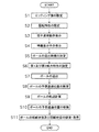
本実施形態の野球ゲームの各種機能の実行概要を、まず、図3に示すフローチャートを用いて説明する。
[How to execute various functions in the game]
An outline of execution of various functions of the baseball game of the present embodiment will be described first with reference to the flowchart shown in FIG.
主に、投手キャラクタ30、捕手キャラクタ31、バッターキャラクタ32、およびボールキャラクタ33をテレビジョンモニタ20に表示して、コントローラ17の操作により、投手キャラクタ30からボールキャラクタ33が送出される野球ゲームでは、通過領域設定ステップにおいて、ヒッティング面40が、制御部1によって、ボールキャラクタ33の送出位置とボールキャラクタ33の到達位置との間でホームベース35上方に設定される(S1)。まず、回転特性設定ステップにおいて、コントローラ17から回転特性指示要求を投手キャラクタ30に与えることにより、投手キャラクタ30から送出されるボールキャラクタ33に回転特性が設定される(S2)。次に、投手キャラクタ30にコントローラ17から動作開始要求を与え、投手キャラクタ30に送球動作を開始させる。すると、投手キャラクタ30の送球動作がテレビジョンモニタ20に表示される(S3)。このとき、投手キャラクタ30がボールを送球する時機を示す時機表示子42が捕手キャラクタ31の前方に表示される(S4)。この状態で、投手キャラクタ30がコントローラ17からボールの送球要求を受けると、投手キャラクタ30がボールを送球する時機が決定される(S5)。このとき、第1および第2威力特性設定ステップにおいて、ボールキャラクタ33が投手キャラクタ30から送出される時機に応じて、第1および第2威力特性が、ボールキャラクタ33に設定される(S6)。そして、ボールキャラクタ33が投手キャラクタ30から捕手キャラクタ31に向けて送出される(S7)。ボールキャラクタ33が投手キャラクタ30から送出されると、通過位置設定ステップにおいて、ボールキャラクタ33の予想通過位置60がヒッティング面40に設定される(S8)。そして、軌道設定ステップにおいて、投手キャラクタ30から送出されたボールキャラクタ33の軌道が、ボールキャラクタ33の送出位置とボールキャラクタ33の到達位置との間で、第2威力特性および回転特性に基づいて、制御部1により設定される(S9)。さらに、通過位置移動ステップにおいて、ボールキャラクタ33の予想通過位置60が、ボールの軌道上のボールキャラクタ33の位置に応じてヒッティング面40で制御部1により制御され移動させられる(S10)。そして、威力状態表示ステップと回転状態表示ステップとにおいて、ボールキャラクタ33の球威状態に対応した球威記号61と回転状態に対応した回転記号62とが、ヒッティング面40で移動させられる予想通過位置60において、第1威力特性と回転特性とに基づいてテレビジョンモニタ20に表示される(S11)。
In a baseball game in which a
〔ゲームの実行概要〕
上記のような各種機能を有する野球ゲームが実行された場合の説明を、テレビジョンモニタ20に表示される画面を用いて説明する。
[Outline of game execution]
The description when the baseball game having various functions as described above is executed will be described using a screen displayed on the
テレビジョンモニタ20の画面には、たとえば図4から図11に示すように、主に、投手キャラクタ30、捕手キャラクタ31、バッターキャラクタ32、およびボールキャラクタ33が表示されている。投手キャラクタ30は画面の略中央部に、捕手キャラクタ31は画面の上部に、バッターキャラクタ32は画面の右側部に、表示されている。ホームベース35上方と捕手キャラクタ31の前方とには、図4および図8に示すように、ストライクゾーン41が表示されている。ここで、図4および図8は、投手キャラクタ30がボールキャラクタ33を送出する前の一表示画面である。
For example, as shown in FIGS. 4 to 11, a
プレイヤによってコントローラ17の上方向キー17U、下方向キー17D、左方向キー17Lおよび右方向キー17Rが押されると、投手キャラクタ30の持ち球の中からボールの球種が決定される。これらコントローラ17の各種キーが押されたときに、投手キャラクタ30から送出されるボールキャラクタ33に回転特性が設定される。たとえば、上方向キー17Uには4シーム直球、下方向キー17Dにはフォーク、左方向キー17Lにはスライダー、右方向キー17Rにはシュート等が割り当てられている。
When the player presses the up key 17U, the down key 17D, the
プレイヤによってコントローラ17の第3ボタン17cが押されると、図5および図9に示すように、投手キャラクタ30は投球動作を開始しはじめる。このとき、時機表示子42が捕手キャラクタ31のミット位置に表示される。時機表示子42は、投手キャラクタ30がボールをリリースするときのタイミングを計るための指標になる。この時機表示子42は、投手キャラクタ30から捕手キャラクタ31にボールを投げ込むときのボールのコース位置を示す円形状のコースマーク42aと、コースマーク42aを取り囲むように形成される時機表示リング42bとからなる。時機表示リング42bは、投手キャラクタ30が投球動作を開始すると、コースマーク42aに向けて徐々に小さくなっていく。そして、図6に示すように、時機表示リング42bがコースマーク42aに重なったときにコントローラ17の第2ボタン17bが押されると、最適リリースポイントで投手キャラクタ30にボールをリリースさせることができる。そして、投手キャラクタ30からボールがリリースされた後には、コースマークがボールの軌道上のボールキャラクタ33の位置変化に連動して移動していく。しかしながら、時機表示リング42bがコースマーク42aに重なる前や、時機表示リング42bがコースマーク42aに重なった後に再度逆方向に大きくなるときに(図10参照)、コントローラ17の第2ボタン17bが押されると、最適リリースポイントからずれたポイントで投手キャラクタ30にボールをリリースさせることになる。そして、投手キャラクタ30からボールがリリースされた後には、コースマークがボールの軌道上のボールキャラクタ33の位置変化に連動して移動していく。ここで、投手キャラクタ30に最適リリースポイントでボールをリリースさせることができると、ボールキャラクタ33には、減速度の小さい第1威力特性と軌道変化率の大きい第2威力特性とが設定される。つまり、ボールキャラクタ33には、球威およびキレのあるボール特性が設定される。しかしながら、投手キャラクタ30に最適リリースポイントからはずれたポイントでボールをリリースさせてしまうと、ボールキャラクタ33には、減速度の大きい第1威力特性と軌道変化率の小さい第2威力特性とが設定される。つまり、リリースポイントがコースマーク42aからずれればずれるほど、ボールキャラクタ33には、球威およびキレの悪いボール特性が設定される。このように、ボールキャラクタ33が投手キャラクタ30から送出される時機に応じて、ボールキャラクタ33の第1および第2威力特性がボールキャラクタ33に設定される。なお、軌道変化率が大きい場合、ボールキャラクタ33の軌道はバッターキャラクタ32の近傍で変化し、軌道変化率が小さい場合、ボールキャラクタ33の軌道はバッターキャラクタ32から離れた位置から変化する。
When the
また、投手キャラクタ30に最適リリースポイントでボールをリリースさせることができるか否かによって、投手キャラクタ30から送出されるボールのコントロールの良し悪しが決定される。投手キャラクタ30に最適リリースポイントでボールをリリースさせることができれば、投手キャラクタ30にコントロールの甘くないボールを送出させることができる。しかしながら、投手キャラクタ30に最適リリースポイントからはずれたポイントでボールをリリースさせてしまうと、投手キャラクタ30にコントロールの甘いボールを送出させることになる。つまり、リリースポイントがコースマーク42aからずれればずれるほど、投手キャラクタ30にコントロールの甘いボールを送出させることになる。このように、ボールキャラクタ33が投手キャラクタ30から送出される時機に応じて、投手キャラクタ30のコントロール(制球力)が決定される。
Whether the
ボールキャラクタ33が投手キャラクタ30から捕手キャラクタ31に向けて送出されると、投手キャラクタ30から送出されたボールキャラクタ33の軌道は、ボールキャラクタ33の送出位置とボールキャラクタ33の到達位置との間で第2威力特性および回転特性に基づいて設定される。このとき、ヒッティング面40のボールキャラクタの球威状態(威力状態)に対応した球威記号61と回転状態に対応した回転記号62とが、第1威力特性と回転特性とに基づいてヒッティング面40の予想通過位置60でテレビジョンモニタ画面に表示される。そして、ボールキャラクタ33が軌道上を移動していくにつれて、ボールキャラクタの球威状態に対応した球威記号61と回転状態に対応した回転記号62とが、予想通過位置60とともにヒッティング面40で移動する様子がテレビジョンモニタ画面に表示される。このとき、図5から図7および図9から図11に示すように、ヒッティング面40に表示されていたストライクゾーン41は、テレビジョンモニタ画面から消失している。なお、実際のゲームにおいては、ヒッティング面40は表示されておらず、ここでは、ヒッティング面40に関する説明を行うために、図4から図11においてヒッティング面40を破線にて示した。
When the
ボールキャラクタの球威状態は、ボールキャラクタ33が投手キャラクタ30から送出される時機に応じて設定されるボールキャラクタ33の第1威力特性に基づいて定められる。ここでは、ボールキャラクタの球威状態は減速度に基づいて決定されている。減速度を設定するため減速度データは、記憶部2に格納されており、この減速度データに基づいて、ボールキャラクタ33は送出位置と到達位置との間で減速させられる。ボールキャラクタの球威状態に対応した球威記号61は、図7および図11に示すように、ヒッティング面におけるボールキャラクタの大きさの違いで表示される。たとえば、減速度が小さいときすなわちボールに球威があるときはヒッティング面のボールキャラクタが予想通過位置60において小さく表示され(図7参照)、減速度が大きいときすなわちボールに球威がないときはヒッティング面のボールキャラクタが予想通過位置60において大きく表示される(図11参照)。このように予想通過位置60において大きさで表現されたボールキャラクタの球威状態に対応した球威記号61は、ボールキャラクタの予想通過位置60とともに、ヒッティング面40を移動していく。なお、ヒッティング面のボールキャラクタが予想通過位置60において小さく表示された状態は、ボールに球威だけでなくキレもあることを表現しており、ボールキャラクタ33はバッターキャラクタ32の近傍で軌道を変化させる。ヒッティング面のボールキャラクタが予想通過位置60において大きく表示された状態は、ボールに球威だけでなくキレもないことを表現しており、ボールキャラクタ33はバッターキャラクタ32から離れた位置から軌道を変化させる。
The ball character's ball power state is determined based on the first power characteristic of the
ボールキャラクタの回転状態は、たとえば図12に示すように、ボールの球種に応じたボールキャラクタ33の回転方向データ70とボールキャラクタ33の回転速度データ71とに基づいて決定される。ここで、これらボールキャラクタ33の回転方向データ70とボールキャラクタ33の回転速度データ71とは、記憶部2に格納されている。ボールキャラクタの回転状態に対応した回転記号62は、図13に示すように、ボールキャラクタの複数の2次元時系列画像データ80,81,82,90,91,92を連続的につなぎ合わせることにより動画として表現される。ボールキャラクタの複数の2次元時系列画像データ80,81,82,90,91,92には、4シーム用と2シーム用のパターンデータ72が用意されている(図12参照)。これら複数の2次元時系列画像データ80,81,82,90,91,92は、ボールキャラクタの回転方向データ70に基づいて回転方向が設定され、ボールキャラクタの回転速度データ71に基づいて回転速度が設定される。たとえば、球種が4シーム直球である場合は、図13(a1)から図13(a3)に示した複数の4シーム用の画像データ80,81,82が用いられる。そして、4シーム用の画像データ80,81,82を図13(a1)から図13(a3)へと連続的につなぎ合わせて、ボールキャラクタ33が上方に回転する状態が動画として表示される。このとき、画像データ80,81,82をつなぎ合わせるときの時間間隔を短く設定することにより、ボールキャラクタ33が上方に高速で回転する状態が動画として表示される。同様に、球種がスライダーである場合は、ボールキャラクタ33が左方向に高速で回転する状態が動画として表示される(図12参照)。たとえば、球種がパームボールである場合は、図13(b1)から図13(b3)に示した複数の2シーム用の画像データ90,91,92が用いられる。そして、2シーム用の画像データ90,91,92を図13(b1)から図13(b3)へと連続的につなぎ合わせて、ボールキャラクタ33が上方に回転する状態が動画として表示される。このとき、画像データ90,91,92をつなぎ合わせるときの時間間隔を長く設定することにより、ボールキャラクタ33が上方に低速で回転する状態が動画として表示される。同様に、球種がチェンジアップである場合は、ボールキャラクタ33が上方に中程度の速度で回転する状態が動画として表示される(図12参照)。このように予想通過位置60に表示されたボールキャラクタの回転状態に対応した回転記号62は、ボールキャラクタの予想通過位置60の移動に応じて、ヒッティング面40に表示されヒッティング面40を移動していく。
For example, as shown in FIG. 12, the rotation state of the ball character is determined based on the
本実施形態では、回転特性に基づいて定められるボールキャラクタの回転状態が、ヒッティング面40で移動させられる予想通過位置60に連続的に表示されるようになっている。これにより、プレイヤは、予想通過位置60に連続的に表示されるボールキャラクタの回転状態を見て、ヒッティング面40のボールキャラクタが移動していく方向を事前に予測することができる。つまり、プレイヤは、ヒッティング面40の予想通過位置60の情報から、ヒッティング面40のボールキャラクタが移動していく方向を事前に予測しやすくなる。また、威力特性がボールキャラクタ33に設定され、威力特性に基づいて定められるボールキャラクタの威力状態61がヒッティング面40の予想通過位置60に表示されるようになっている。これにより、プレイヤは、威力特性に基づいて定められるボールキャラクタの威力状態61を見て、ボールキャラクタの威力を事前に把握することができる。つまり、プレイヤは、ヒッティング面40の予想通過位置60の情報から、ボールキャラクタ33の威力を把握することができる。
In the present embodiment, the rotation state of the ball character determined based on the rotation characteristics is continuously displayed at the expected passing position 60 that is moved on the hitting
〔他の実施形態〕
(a) 前記実施形態では、家庭用ゲーム装置を用いた場合の例を示したが、ゲーム装置は、前記実施形態に限定されず、モニタが一体に構成された業務用ゲーム装置、ゲームプログラムを実行することによってゲーム装置として機能するパーソナルコンピュータやワークステーションなどにも同様に適用することができる。
Other Embodiment
(A) In the above-described embodiment, an example in which a home-use game device is used has been described. However, the game device is not limited to the above-described embodiment, and an arcade game device and a game program in which a monitor is integrated are provided. The present invention can be similarly applied to a personal computer or a workstation that functions as a game device by executing.
(b) 前記実施形態では、野球ゲームを用いた場合の例を示したが、ゲームは、前記実施形態に限定されず、回転状態や威力状態を表現可能な移動体を用いたゲームであれば、どのようなものでも良い。 (B) In the said embodiment, although the example at the time of using a baseball game was shown, if a game is not limited to the said embodiment, If it is a game using the mobile body which can express a rotation state and a power state Anything is fine.
(c) 前記実施形態では、ヒッティング面40(予想通過表示領域)を矩形状に設定した場合の例を示したが、ヒッティング面40の形状は、前記実施形態に限定されず、任意の形状に設定することが可能である。
(C) In the above-described embodiment, an example in which the hitting surface 40 (expected passage display area) is set to a rectangular shape has been described. However, the shape of the hitting
(d) 本発明には、前述した方法を実行するプログラムおよびこのプログラムを記録したコンピュータ読み取り可能な記録媒体も含まれる。この記録媒体としては、たとえば、コンピュータ読み取り可能なフレキシブルディスク、半導体メモリ、CD−ROM、DVD、MO、ROMカセット、その他のものが挙げられる。 (D) The present invention includes a program for executing the above-described method and a computer-readable recording medium on which the program is recorded. Examples of the recording medium include a computer-readable flexible disk, semiconductor memory, CD-ROM, DVD, MO, ROM cassette, and others.
1 制御部
2 メモリ部
3 画像表示部
4 音声出力部
5 操作入力部
6 バス
7 CPU
8 信号処理プロセッサ
9 画像処理プロセッサ
10 記録媒体
13 スピーカー
17 コントローラ
20 テレビジョンモニタ
30 投手キャラクタ
31 捕手キャラクタ
33 ボールキャラクタ
40 ヒッティング面(予想通過表示領域)
42 時機表示子
42a コースマーク
42b 時機表示リング
50 通過領域設定手段
51 通過位置設定手段
52 第1威力特性設定手段
53 威力状態表示手段
54 回転特性設定手段
55 第2威力特性設定手段
56 軌道変化手段
57 通過位置移動手段
58 回転状態表示手段
60 予想通過位置
61 球威状態
62 回転状態
70 回転方向データ
71 回転速度データ
72 パターンデータ
80,81,82,90,91,92 時系列画像データ
DESCRIPTION OF
8
42
Claims (3)
前記移動体の送出位置と前記移動体の到達位置との間の所定位置の座標を制御部に計算させ、制御部により計算された前記所定位置の座標を含む平面内の所定範囲を制御部に計算させ、前記所定範囲を前記移動体の予想通過表示領域として制御部に認識させる通過領域設定機能と、
前記移動体の送出位置の座標および前記移動体の到達位置の座標を結ぶ直線が前記予想通過表示領域に交差する座標を制御部に計算させ、前記座標を前記移動体の予想通過位置として制御部に認識させる通過位置設定機能と、
前記コントローラからの回転特性指示要求が制御部に認識されたときに、回転方向データを含む回転特性データを記憶部から読み出し前記回転方向データに対応した複数の移動体の画像データを制御部に選択させる回転特性設定機能と、
前記回転方向データを含む回転特性データに基づいて前記送出位置と前記到達位置との間の前記移動体の軌道を制御部に計算させる軌道設定機能と、
前記軌道上の前記移動体の座標を制御部に計算させ、前記軌道上の前記移動体の座標において前記移動体の軌道に接する接線が前記予想通過表示領域に交わる交点座標を制御部に計算させ、制御部に計算させた前記交点座標を新たな前記予想通過位置として制御部に認識させる通過位置移動機能と、
前記回転方向データに対応した複数の画像データを連続的につなぎ合わせることにより、前記回転方向データに対応した複数の画像データを、制御部から画像表示部に発行される回転表示要求に基づいて制御部に修正計算させた前記予想通過位置の座標位置において前記画像表示部に連続的に表示する回転状態表示機能と、
を実現させるためのゲームプログラム。 A computer capable of displaying a character and a moving body on a monitor and realizing a game in which the moving body is sent out from the character by operating a controller.
The control unit calculates coordinates of a predetermined position between the sending position of the moving body and the arrival position of the moving body, and a predetermined range in a plane including the coordinates of the predetermined position calculated by the control unit is set in the control unit. A passing area setting function for calculating and allowing the control unit to recognize the predetermined range as an expected passing display area of the moving body;
The control unit calculates coordinates at which a straight line connecting the coordinates of the sending position of the moving body and the coordinates of the reaching position of the moving body intersects the predicted passing display area, and the control unit sets the coordinates as the expected passing position of the moving body. Passing position setting function to be recognized by
When the controller recognizes a rotation characteristic instruction request from the controller, the rotation characteristic data including the rotation direction data is read from the storage unit, and image data of a plurality of moving bodies corresponding to the rotation direction data is selected by the control unit Rotation characteristics setting function
A trajectory setting function for causing a control unit to calculate a trajectory of the moving body between the delivery position and the arrival position based on rotational characteristic data including the rotation direction data;
Let the control unit calculate the coordinates of the moving body on the trajectory, and let the control unit calculate the intersection coordinates where the tangent line that touches the trajectory of the moving body intersects the predicted passing display area in the coordinates of the moving body on the trajectory. A passing position moving function that causes the control unit to recognize the intersection coordinates calculated by the control unit as the new predicted passing position;
A plurality of image data corresponding to the rotation direction data is controlled based on a rotation display request issued from the control unit to the image display unit by continuously connecting the plurality of image data corresponding to the rotation direction data. A rotation state display function for continuously displaying on the image display unit at the coordinate position of the predicted passing position calculated to be corrected by the unit;
A game program to make it happen.
前記回転状態表示機能では、前記移動体の回転速度データに基づいて、前記回転方向データに対応した複数の画像データを連続的に前記画像表示部に表示するときの時間間隔が制御部に認識され、前記回転方向データに対応した複数の画像データが、制御部に修正計算させた前記予想通過位置の座標位置において前記時間間隔で前記画像表示部に連続的に表示される、
請求項1に記載のゲームプログラム。 The rotation characteristic data further includes rotation speed data of the moving body,
In the rotation state display function, the control unit recognizes a time interval when a plurality of image data corresponding to the rotation direction data is continuously displayed on the image display unit based on the rotation speed data of the moving body. A plurality of image data corresponding to the rotation direction data is continuously displayed on the image display unit at the time interval at the coordinate position of the expected passing position that is corrected and calculated by the control unit.
The game program according to claim 1.
前記コントローラからの移動体送出要求が制御部に認識された時機に応じて加速度データを含む第1威力特性データを記憶部から読み出し、前記加速度データに基づいて前記移動体の送出位置と前記移動体の到達位置の間で前記移動体を加減速させる第1威力特性設定機能と、
記憶部に格納された複数の画像データの大きさを前記移動体の送出位置と前記移動体の到達位置の間で加減速する前記移動体の状態に対応するように制御部に変更させ、制御部に大きさを変更させた複数の前記移動体の画像データを、制御部から画像表示部に発行される威力表示要求に基づいて、前記予想通過表示領域の前記予想通過位置において前記画像表示部に表示する威力状態表示機能と、
をさらに実現させるための請求項1又は2に記載のゲームプログラム。 In the computer,
Reads the first power characteristic data including acceleration data in accordance with the timing at which the moving object transmission request is recognized by the control unit from the front Symbol controller from the storage unit, the moving and delivery position of the moving object based on the acceleration data A first power characteristic setting function for accelerating or decelerating the moving body between the body reaching positions;
The control unit changes the size of the plurality of image data stored in the storage unit so as to correspond to the state of the moving body that accelerates or decelerates between the sending position of the moving body and the arrival position of the moving body. The image display unit at the expected passage position of the expected passage display area based on a power display request issued from the control unit to the image display unit, the image data of the plurality of moving bodies whose sizes are changed by the unit Power status display function to be displayed on,
The game program according to claim 1 or 2 for realizing further.
Priority Applications (9)
| Application Number | Priority Date | Filing Date | Title |
|---|---|---|---|
| JP2004043616A JP3789919B2 (en) | 2004-02-19 | 2004-02-19 | GAME PROGRAM, GAME DEVICE, AND GAME METHOD |
| KR1020087013282A KR100984805B1 (en) | 2004-02-19 | 2005-01-13 | Computer readable medium on which game program is recorded, game device, and game control method |
| EP05703524A EP1716895A4 (en) | 2004-02-19 | 2005-01-13 | Game program, game device, and game method |
| CN2005800053671A CN1921915B (en) | 2004-02-19 | 2005-01-13 | Game device and game method |
| KR1020067017500A KR100853831B1 (en) | 2004-02-19 | 2005-01-13 | Computer readable media on which game program is recorded, game device, and game control method |
| PCT/JP2005/000285 WO2005079940A1 (en) | 2004-02-19 | 2005-01-13 | Game program, game device, and game method |
| TW094103257A TW200534120A (en) | 2004-02-19 | 2005-02-02 | Game program, game device, and game method |
| US11/465,126 US7878890B2 (en) | 2004-02-19 | 2006-08-17 | Game program, game device, and game method |
| HK07103554.5A HK1096326A1 (en) | 2004-02-19 | 2007-04-03 | Video game device,and video game method |
Applications Claiming Priority (1)
| Application Number | Priority Date | Filing Date | Title |
|---|---|---|---|
| JP2004043616A JP3789919B2 (en) | 2004-02-19 | 2004-02-19 | GAME PROGRAM, GAME DEVICE, AND GAME METHOD |
Related Child Applications (1)
| Application Number | Title | Priority Date | Filing Date |
|---|---|---|---|
| JP2006038218A Division JP4122030B2 (en) | 2006-02-15 | 2006-02-15 | GAME PROGRAM, GAME DEVICE, AND GAME METHOD |
Publications (2)
| Publication Number | Publication Date |
|---|---|
| JP2005230288A JP2005230288A (en) | 2005-09-02 |
| JP3789919B2 true JP3789919B2 (en) | 2006-06-28 |
Family
ID=34879317
Family Applications (1)
| Application Number | Title | Priority Date | Filing Date |
|---|---|---|---|
| JP2004043616A Expired - Fee Related JP3789919B2 (en) | 2004-02-19 | 2004-02-19 | GAME PROGRAM, GAME DEVICE, AND GAME METHOD |
Country Status (8)
| Country | Link |
|---|---|
| US (1) | US7878890B2 (en) |
| EP (1) | EP1716895A4 (en) |
| JP (1) | JP3789919B2 (en) |
| KR (2) | KR100853831B1 (en) |
| CN (1) | CN1921915B (en) |
| HK (1) | HK1096326A1 (en) |
| TW (1) | TW200534120A (en) |
| WO (1) | WO2005079940A1 (en) |
Families Citing this family (37)
| Publication number | Priority date | Publication date | Assignee | Title |
|---|---|---|---|---|
| JP3735358B2 (en) * | 2003-09-12 | 2006-01-18 | コナミ株式会社 | Video game program, video game apparatus, and video game method |
| JP3789919B2 (en) * | 2004-02-19 | 2006-06-28 | コナミ株式会社 | GAME PROGRAM, GAME DEVICE, AND GAME METHOD |
| PT1926535E (en) * | 2005-09-19 | 2010-08-27 | John Joe O Sullivan | Training device |
| JP3947549B2 (en) * | 2005-12-26 | 2007-07-25 | 株式会社コナミデジタルエンタテインメント | Video game program, video game apparatus, and video game control method |
| JP4883759B2 (en) * | 2006-01-13 | 2012-02-22 | 株式会社バンダイナムコゲームス | Program, information storage medium, and image generation system |
| JP3924584B1 (en) | 2006-02-23 | 2007-06-06 | 株式会社コナミデジタルエンタテインメント | GAME PROGRAM, GAME DEVICE, AND GAME CONTROL METHOD |
| JP3965198B1 (en) * | 2006-03-16 | 2007-08-29 | 株式会社コナミデジタルエンタテインメント | GAME PROGRAM, GAME DEVICE, AND GAME CONTROL METHOD |
| US20080215974A1 (en) * | 2007-03-01 | 2008-09-04 | Phil Harrison | Interactive user controlled avatar animations |
| JP4610647B2 (en) * | 2008-02-28 | 2011-01-12 | 株式会社コナミデジタルエンタテインメント | NETWORK GAME SYSTEM, NETWORK GAME PROGRAM, NETWORK GAME DEVICE, AND NETWORK GAME CONTROL METHOD |
| US8890774B2 (en) * | 2010-02-09 | 2014-11-18 | Disney Enterprises, Inc. | Heads-up display for a gaming environment |
| CN102446359B (en) * | 2010-10-12 | 2014-01-22 | 深圳泰山在线科技有限公司 | Small ball sport processing method based on computer and system thereof |
| JP5174123B2 (en) * | 2010-10-28 | 2013-04-03 | 株式会社コナミデジタルエンタテインメント | GAME DEVICE, GAME CONTROL METHOD, AND PROGRAM |
| JP5282110B2 (en) * | 2011-03-04 | 2013-09-04 | 株式会社コナミデジタルエンタテインメント | GAME DEVICE AND GAME CONTROL PROGRAM |
| CN104136086B (en) * | 2012-03-02 | 2017-02-22 | 索尼电脑娱乐公司 | Information processing system, method and equipment |
| US9547316B2 (en) | 2012-09-07 | 2017-01-17 | Opower, Inc. | Thermostat classification method and system |
| JP5735472B2 (en) * | 2012-10-26 | 2015-06-17 | 株式会社 ディー・エヌ・エー | Game providing device |
| US10067516B2 (en) | 2013-01-22 | 2018-09-04 | Opower, Inc. | Method and system to control thermostat using biofeedback |
| US10719797B2 (en) | 2013-05-10 | 2020-07-21 | Opower, Inc. | Method of tracking and reporting energy performance for businesses |
| US10001792B1 (en) | 2013-06-12 | 2018-06-19 | Opower, Inc. | System and method for determining occupancy schedule for controlling a thermostat |
| JP5898169B2 (en) * | 2013-12-12 | 2016-04-06 | 株式会社コナミデジタルエンタテインメント | GAME DEVICE, GAME SYSTEM, AND PROGRAM |
| US9727063B1 (en) | 2014-04-01 | 2017-08-08 | Opower, Inc. | Thermostat set point identification |
| US10019739B1 (en) | 2014-04-25 | 2018-07-10 | Opower, Inc. | Energy usage alerts for a climate control device |
| USD753167S1 (en) * | 2014-06-27 | 2016-04-05 | Opower, Inc. | Display screen of a communications terminal with graphical user interface |
| USD760261S1 (en) * | 2014-06-27 | 2016-06-28 | Opower, Inc. | Display screen of a communications terminal with graphical user interface |
| US10410130B1 (en) | 2014-08-07 | 2019-09-10 | Opower, Inc. | Inferring residential home characteristics based on energy data |
| US10572889B2 (en) | 2014-08-07 | 2020-02-25 | Opower, Inc. | Advanced notification to enable usage reduction |
| US10033184B2 (en) | 2014-11-13 | 2018-07-24 | Opower, Inc. | Demand response device configured to provide comparative consumption information relating to proximate users or consumers |
| US11093950B2 (en) | 2015-02-02 | 2021-08-17 | Opower, Inc. | Customer activity score |
| US10198483B2 (en) | 2015-02-02 | 2019-02-05 | Opower, Inc. | Classification engine for identifying business hours |
| US10074097B2 (en) | 2015-02-03 | 2018-09-11 | Opower, Inc. | Classification engine for classifying businesses based on power consumption |
| US10371861B2 (en) | 2015-02-13 | 2019-08-06 | Opower, Inc. | Notification techniques for reducing energy usage |
| US10817789B2 (en) | 2015-06-09 | 2020-10-27 | Opower, Inc. | Determination of optimal energy storage methods at electric customer service points |
| US9958360B2 (en) | 2015-08-05 | 2018-05-01 | Opower, Inc. | Energy audit device |
| US10559044B2 (en) | 2015-11-20 | 2020-02-11 | Opower, Inc. | Identification of peak days |
| US20200005165A1 (en) * | 2018-06-28 | 2020-01-02 | International Business Machines Corporation | Dynamically determining a region of effectiveness of athletes during game play based on predictive factors |
| CN109589604A (en) * | 2019-01-24 | 2019-04-09 | 网易(杭州)网络有限公司 | Control method, control device, storage medium and the processor of virtual objects |
| JP2021041181A (en) * | 2020-11-05 | 2021-03-18 | 株式会社コナミデジタルエンタテインメント | Game device, game control program, and game control method |
Family Cites Families (35)
| Publication number | Priority date | Publication date | Assignee | Title |
|---|---|---|---|---|
| US3749514A (en) | 1971-09-30 | 1973-07-31 | United Aircraft Corp | Blade attachment |
| EP0499874A3 (en) | 1986-09-11 | 1992-10-28 | Hughes Aircraft Company | Digital visual and sensor simulation system for generating realistic scenes |
| US5435554A (en) * | 1993-03-08 | 1995-07-25 | Atari Games Corporation | Baseball simulation system |
| US5816953A (en) * | 1996-07-02 | 1998-10-06 | Cleveland; William C. | Method and apparatus for interactive tennis practice |
| KR100320262B1 (en) * | 1996-08-05 | 2002-04-22 | 기노시타 구니아키 | Apparantus for and method of designation a point on displayed image, and readable recording medium storing program for designationg a point on displayed image |
| US6217444B1 (en) * | 1996-09-24 | 2001-04-17 | Konami Co., Ltd. | Simulative golf game system and a method for providing a simulative golf game and a storage medium for storing a simulative golf game program |
| JP3885381B2 (en) * | 1998-09-16 | 2007-02-21 | 株式会社セガ | Game image display method |
| JP4221838B2 (en) * | 1998-09-30 | 2009-02-12 | 株式会社セガ | Game device, hit determination method, and information recording medium |
| JP3359013B2 (en) * | 1999-11-30 | 2002-12-24 | 株式会社ナムコ | Game system and information storage medium |
| JP3403685B2 (en) * | 2000-01-14 | 2003-05-06 | コナミ株式会社 | GAME SYSTEM AND COMPUTER-READABLE STORAGE MEDIUM |
| JP3312018B2 (en) * | 2000-01-14 | 2002-08-05 | コナミ株式会社 | Game system and computer-readable storage medium |
| US7671846B1 (en) | 2000-01-14 | 2010-03-02 | Sony Computer Entertainment Inc. | Computer system having a pressure-sensitive controller, setup method for a pressure-sensitive controller and recording medium that records this method |
| US6461237B1 (en) * | 2000-01-28 | 2002-10-08 | Square Co., Ltd. | Computer readable program product storing program for ball-playing type game, said program, and ball-playing type game processing apparatus and method |
| JP4030249B2 (en) * | 2000-05-19 | 2008-01-09 | 株式会社コナミデジタルエンタテインメント | Computer-readable recording medium recording action game program, action game device and control method thereof |
| JP2001327750A (en) * | 2000-05-19 | 2001-11-27 | Square Co Ltd | Recording medium storing program for processing cursor display of a ball game type game that can be read by computer and program, and device and method for processing cursor display of ball game type game |
| JP2002058868A (en) * | 2000-06-07 | 2002-02-26 | Square Co Ltd | Computer-readable recording medium with ball game program recorded on it, program, and ball game processing device and method |
| JP2002045569A (en) * | 2000-07-31 | 2002-02-12 | Konami Computer Entertainment Osaka:Kk | Computer readable recording medium on which game prigress control program is recorded, server and game progress control method |
| JP2002045572A (en) * | 2000-08-01 | 2002-02-12 | Konami Computer Entertainment Osaka:Kk | Game progress control method, game system, and server |
| ATE472132T1 (en) * | 2000-08-23 | 2010-07-15 | Nintendo Co Ltd | INFORMATION PROCESSING DEVICE, INFORMATION STORAGE MEDIUM AND PROGRAM THEREOF, AND OPERATING DEVICE FOR A SLOT MACHINE |
| JP3443402B2 (en) * | 2001-01-12 | 2003-09-02 | 株式会社コナミコンピュータエンタテインメントスタジオ | Computer-readable recording medium recording action game program, action game control device and method, action game program |
| JP2002233664A (en) * | 2001-02-08 | 2002-08-20 | Konami Computer Entertainment Osaka:Kk | Game progress control program, server for game, and method of controlling game progress |
| WO2002066128A1 (en) * | 2001-02-22 | 2002-08-29 | Sega Corporation | Program for controlling playing of game, and game apparatus for running this program |
| JP3412693B2 (en) * | 2001-06-28 | 2003-06-03 | 株式会社コナミコンピュータエンタテインメント大阪 | Network game progress control system, network game progress control method, and network game progress control program |
| JP2003024639A (en) * | 2001-07-18 | 2003-01-28 | Konami Computer Entertainment Osaka:Kk | Game progress control program, device and method for controlling game progress and server device for game |
| JP4776831B2 (en) * | 2001-09-11 | 2011-09-21 | 株式会社バンダイナムコゲームス | Program, information storage medium, game device, and host device |
| JP4028708B2 (en) | 2001-10-19 | 2007-12-26 | 株式会社コナミデジタルエンタテインメント | GAME DEVICE AND GAME SYSTEM |
| JP3559024B2 (en) * | 2002-04-04 | 2004-08-25 | マイクロソフト コーポレイション | GAME PROGRAM AND GAME DEVICE |
| JP4213011B2 (en) * | 2003-03-10 | 2009-01-21 | 任天堂株式会社 | GAME DEVICE AND GAME PROGRAM |
| US8012003B2 (en) * | 2003-04-10 | 2011-09-06 | Nintendo Co., Ltd. | Baseball videogame having pitching meter, hero mode and user customization features |
| JP4189315B2 (en) * | 2003-12-26 | 2008-12-03 | 任天堂株式会社 | GAME DEVICE AND GAME PROGRAM |
| JP3789919B2 (en) * | 2004-02-19 | 2006-06-28 | コナミ株式会社 | GAME PROGRAM, GAME DEVICE, AND GAME METHOD |
| US7578742B2 (en) * | 2004-03-26 | 2009-08-25 | Nintendo Co., Ltd. | Recording medium storing video game program and video game device |
| US20060068916A1 (en) * | 2004-09-30 | 2006-03-30 | Aruze Corporation | Gaming server and gaming system |
| JP5105458B2 (en) * | 2005-10-04 | 2012-12-26 | 任天堂株式会社 | Game system and game program |
| JP5415730B2 (en) * | 2008-09-04 | 2014-02-12 | 任天堂株式会社 | Image processing program, image processing apparatus, image processing method, and image processing system |
-
2004
- 2004-02-19 JP JP2004043616A patent/JP3789919B2/en not_active Expired - Fee Related
-
2005
- 2005-01-13 CN CN2005800053671A patent/CN1921915B/en not_active Expired - Fee Related
- 2005-01-13 WO PCT/JP2005/000285 patent/WO2005079940A1/en active Application Filing
- 2005-01-13 KR KR1020067017500A patent/KR100853831B1/en active IP Right Grant
- 2005-01-13 EP EP05703524A patent/EP1716895A4/en not_active Withdrawn
- 2005-01-13 KR KR1020087013282A patent/KR100984805B1/en not_active IP Right Cessation
- 2005-02-02 TW TW094103257A patent/TW200534120A/en not_active IP Right Cessation
-
2006
- 2006-08-17 US US11/465,126 patent/US7878890B2/en not_active Expired - Fee Related
-
2007
- 2007-04-03 HK HK07103554.5A patent/HK1096326A1/en not_active IP Right Cessation
Also Published As
| Publication number | Publication date |
|---|---|
| TW200534120A (en) | 2005-10-16 |
| TWI297841B (en) | 2008-06-11 |
| KR20080056777A (en) | 2008-06-23 |
| KR100984805B1 (en) | 2010-10-05 |
| CN1921915A (en) | 2007-02-28 |
| JP2005230288A (en) | 2005-09-02 |
| EP1716895A4 (en) | 2007-12-12 |
| US20060276241A1 (en) | 2006-12-07 |
| HK1096326A1 (en) | 2007-06-01 |
| WO2005079940A1 (en) | 2005-09-01 |
| US7878890B2 (en) | 2011-02-01 |
| KR20060114027A (en) | 2006-11-03 |
| KR100853831B1 (en) | 2008-08-22 |
| CN1921915B (en) | 2011-06-01 |
| EP1716895A1 (en) | 2006-11-02 |
Similar Documents
| Publication | Publication Date | Title |
|---|---|---|
| JP3789919B2 (en) | GAME PROGRAM, GAME DEVICE, AND GAME METHOD | |
| JP2009207780A (en) | Game program, game machine and game control method | |
| JP3892889B1 (en) | GAME PROGRAM, GAME DEVICE, AND GAME CONTROL METHOD | |
| JP4463289B2 (en) | GAME PROGRAM, GAME DEVICE, AND GAME CONTROL METHOD | |
| JP4521020B2 (en) | GAME PROGRAM, GAME DEVICE, AND GAME CONTROL METHOD | |
| JP2009066058A (en) | Game program, game apparatus, and game control method | |
| JP3735358B2 (en) | Video game program, video game apparatus, and video game method | |
| JP3924584B1 (en) | GAME PROGRAM, GAME DEVICE, AND GAME CONTROL METHOD | |
| JP4164101B2 (en) | GAME PROGRAM, GAME DEVICE, AND GAME CONTROL METHOD | |
| JP4122030B2 (en) | GAME PROGRAM, GAME DEVICE, AND GAME METHOD | |
| JP3934660B1 (en) | Video game program, video game apparatus, and video game control method | |
| JP2007068824A (en) | Game program, game apparatus and game method | |
| KR20080080679A (en) | Video game program, video game machine, and video game control method | |
| JP2007330675A (en) | Game program, game apparatus, and method of controlling game | |
| JP3965198B1 (en) | GAME PROGRAM, GAME DEVICE, AND GAME CONTROL METHOD | |
| JP3762919B2 (en) | Video game program, video game apparatus, and video game method | |
| JP2007313018A (en) | Game program, game device and game control method |
Legal Events
| Date | Code | Title | Description |
|---|---|---|---|
| A521 | Request for written amendment filed |
Free format text: JAPANESE INTERMEDIATE CODE: A523 Effective date: 20050606 |
|
| A521 | Request for written amendment filed |
Free format text: JAPANESE INTERMEDIATE CODE: A523 Effective date: 20050623 |
|
| A02 | Decision of refusal |
Free format text: JAPANESE INTERMEDIATE CODE: A02 Effective date: 20050913 |
|
| A521 | Request for written amendment filed |
Free format text: JAPANESE INTERMEDIATE CODE: A523 Effective date: 20051114 |
|
| A911 | Transfer to examiner for re-examination before appeal (zenchi) |
Free format text: JAPANESE INTERMEDIATE CODE: A911 Effective date: 20051117 |
|
| A131 | Notification of reasons for refusal |
Free format text: JAPANESE INTERMEDIATE CODE: A131 Effective date: 20051220 |
|
| A521 | Request for written amendment filed |
Free format text: JAPANESE INTERMEDIATE CODE: A523 Effective date: 20060215 |
|
| TRDD | Decision of grant or rejection written | ||
| A01 | Written decision to grant a patent or to grant a registration (utility model) |
Free format text: JAPANESE INTERMEDIATE CODE: A01 Effective date: 20060322 |
|
| A61 | First payment of annual fees (during grant procedure) |
Free format text: JAPANESE INTERMEDIATE CODE: A61 Effective date: 20060329 |
|
| R150 | Certificate of patent or registration of utility model |
Ref document number: 3789919 Country of ref document: JP Free format text: JAPANESE INTERMEDIATE CODE: R150 Free format text: JAPANESE INTERMEDIATE CODE: R150 |
|
| A711 | Notification of change in applicant |
Free format text: JAPANESE INTERMEDIATE CODE: A712 Effective date: 20060427 |
|
| S111 | Request for change of ownership or part of ownership |
Free format text: JAPANESE INTERMEDIATE CODE: R313111 |
|
| R350 | Written notification of registration of transfer |
Free format text: JAPANESE INTERMEDIATE CODE: R350 |
|
| FPAY | Renewal fee payment (event date is renewal date of database) |
Free format text: PAYMENT UNTIL: 20090407 Year of fee payment: 3 |
|
| S531 | Written request for registration of change of domicile |
Free format text: JAPANESE INTERMEDIATE CODE: R313531 |
|
| FPAY | Renewal fee payment (event date is renewal date of database) |
Free format text: PAYMENT UNTIL: 20090407 Year of fee payment: 3 |
|
| R350 | Written notification of registration of transfer |
Free format text: JAPANESE INTERMEDIATE CODE: R350 |
|
| FPAY | Renewal fee payment (event date is renewal date of database) |
Free format text: PAYMENT UNTIL: 20090407 Year of fee payment: 3 |
|
| FPAY | Renewal fee payment (event date is renewal date of database) |
Free format text: PAYMENT UNTIL: 20100407 Year of fee payment: 4 |
|
| R250 | Receipt of annual fees |
Free format text: JAPANESE INTERMEDIATE CODE: R250 |
|
| FPAY | Renewal fee payment (event date is renewal date of database) |
Free format text: PAYMENT UNTIL: 20110407 Year of fee payment: 5 |
|
| R250 | Receipt of annual fees |
Free format text: JAPANESE INTERMEDIATE CODE: R250 |
|
| FPAY | Renewal fee payment (event date is renewal date of database) |
Free format text: PAYMENT UNTIL: 20110407 Year of fee payment: 5 |
|
| FPAY | Renewal fee payment (event date is renewal date of database) |
Free format text: PAYMENT UNTIL: 20120407 Year of fee payment: 6 |
|
| R250 | Receipt of annual fees |
Free format text: JAPANESE INTERMEDIATE CODE: R250 |
|
| FPAY | Renewal fee payment (event date is renewal date of database) |
Free format text: PAYMENT UNTIL: 20130407 Year of fee payment: 7 |
|
| R250 | Receipt of annual fees |
Free format text: JAPANESE INTERMEDIATE CODE: R250 |
|
| FPAY | Renewal fee payment (event date is renewal date of database) |
Free format text: PAYMENT UNTIL: 20140407 Year of fee payment: 8 |
|
| R250 | Receipt of annual fees |
Free format text: JAPANESE INTERMEDIATE CODE: R250 |
|
| R250 | Receipt of annual fees |
Free format text: JAPANESE INTERMEDIATE CODE: R250 |
|
| R250 | Receipt of annual fees |
Free format text: JAPANESE INTERMEDIATE CODE: R250 |
|
| R250 | Receipt of annual fees |
Free format text: JAPANESE INTERMEDIATE CODE: R250 |
|
| R250 | Receipt of annual fees |
Free format text: JAPANESE INTERMEDIATE CODE: R250 |
|
| R250 | Receipt of annual fees |
Free format text: JAPANESE INTERMEDIATE CODE: R250 |
|
| R250 | Receipt of annual fees |
Free format text: JAPANESE INTERMEDIATE CODE: R250 |
|
| R250 | Receipt of annual fees |
Free format text: JAPANESE INTERMEDIATE CODE: R250 |
|
| R250 | Receipt of annual fees |
Free format text: JAPANESE INTERMEDIATE CODE: R250 |
|
| R250 | Receipt of annual fees |
Free format text: JAPANESE INTERMEDIATE CODE: R250 |
|
| LAPS | Cancellation because of no payment of annual fees |