JP3786801B2 - Composite tile for cover - Google Patents
Composite tile for cover Download PDFInfo
- Publication number
- JP3786801B2 JP3786801B2 JP17311099A JP17311099A JP3786801B2 JP 3786801 B2 JP3786801 B2 JP 3786801B2 JP 17311099 A JP17311099 A JP 17311099A JP 17311099 A JP17311099 A JP 17311099A JP 3786801 B2 JP3786801 B2 JP 3786801B2
- Authority
- JP
- Japan
- Prior art keywords
- tile
- magnet
- sheet
- bonded
- composite
- Prior art date
- Legal status (The legal status is an assumption and is not a legal conclusion. Google has not performed a legal analysis and makes no representation as to the accuracy of the status listed.)
- Expired - Lifetime
Links
Images


Classifications
-
- E—FIXED CONSTRUCTIONS
- E04—BUILDING
- E04F—FINISHING WORK ON BUILDINGS, e.g. STAIRS, FLOORS
- E04F15/00—Flooring
- E04F15/02—Flooring or floor layers composed of a number of similar elements
- E04F15/02133—Flooring or floor layers composed of a number of similar elements fixed directly to an underlayer by means of magnets, hook and loop-type or similar fasteners, not necessarily involving the side faces of the flooring elements
- E04F15/02144—Flooring or floor layers composed of a number of similar elements fixed directly to an underlayer by means of magnets, hook and loop-type or similar fasteners, not necessarily involving the side faces of the flooring elements by magnets
Landscapes
- Engineering & Computer Science (AREA)
- Architecture (AREA)
- Civil Engineering (AREA)
- Structural Engineering (AREA)
- Finishing Walls (AREA)
Description
【0001】
【発明の属する技術分野】
本発明はあらかじめ鉄製部材又は強磁性体面を有する被着面に貼着でき、建造物の壁面、床面等の内外装用の表装材又は工事現場等の仮設鉄製部材の装飾等に使用できる表装用複合タイルに関するものである。
【0002】
【従来の技術】
従来、建築用として頻繁に用いられる磁器タイル等の窯業系タイルは多くの場合、接合材としてモルタルを用い左官作業により張り付け、あるいは、タイル固定のための固定部材を付設した後、挿入部に対応した形状のタイルを挿入する方法も採られている。窯業系タイルの外、木製、合成樹脂製、金属製など種々のタイルがあり、貼着方法もモルタルに限らず、接着剤など他の貼着手段により壁面や床に貼着する場合もある。
【0003】
【発明が解決しようとする課題】
上記したいずれの施工方法も、タイルを貼着し目地処理を行うことは時間を要し、良質の仕上げには熟練した職人を必要とし、種々の材料から成るタイルを接着剤で固定する場合でも、一定の目地幅に仕上げ、あるいは多様な色や形のタイルを組み合わせて所定の図柄に仕上げることは熟練者による手間のかかる作業が必要であった。
【0004】
本発明は上記のような従来の欠点を解消し、建造物の鉄製部材の表面又はあらかじめ強磁性体面を形成した被着体に、タイルを簡単に貼ることができ、熟練工を必要とせず、施工場所によってはいわゆる日曜大工でもタイルの模様替えができるタイルを提供し、また、貼り替え作業の困難な高所や貼り替えの必要がなく強固な固定の望まれる場所では、施工中は着脱自在に簡単に施工でき、施工完成後は容易に剥がせず長期の固定に耐える表装用複合タイルを提供しようとするものである。
【0005】
【課題を解決するための手段】
上記目的を達成するために、本発明による表装用複合タイルは、強磁性体製の被着体に磁気吸着にて取り付けることができるものであって、タイルと、その裏面に設けられる可撓性のシート状磁石とで構成され、このシート状磁石は、強磁性体製の被着体と接触する面側に、両端が異極となるように配列された縞状の多極着磁が施されていると共に、その中央部がタイルの裏面の略中央部に接着にて貼り合わされていて強磁性体製の被着体に磁気吸着させて引き離す時に吸盤作用を生じせしめる構成となっている。
この構成によれば、シート状磁石が可撓性となっているため、被着体の表面に若干の凹凸があっても安定した施工ができる。
【0006】
なお、タイル裏面に貼り合わせるシート状磁石には、強磁性体製の被着体側に接着剤層が設けられていると、磁力と接着剤によって長期間にわたって強力に固定することができる。
【0007】
また、シート状磁石をタイル周縁の一辺あるいは任意の複数辺を一定寸法突出させると、均一幅の目地が簡単に形成できるので好適である。
【0008】
タイル裏面に貼り合わせるシート状磁石として、アクリルゴム、エチレン・プロピレンゴム、エチレン・プロピレン非共役ジエン三元重合体エラストマー、エチレン・酢酸ビニル共重合体エラストマー、塩素化ポリエチレン、クロロスルフォン化ポリエチレンの中の一種以上を非架橋で使用した有機高分子粘結材を含有した可撓性ボンド磁石を用いた場合、長期間の固定に耐えるタイルを得ることができる。
【0009】
【作用】
上記のように構成した複合タイルを強磁性体の被着面に並行して施工する場合、タイルのシート状磁石の最初と最後の磁極が異極となるように磁極配置されているので、タイルの向きを変えて貼り付けることにより、異極同士隣接し磁極の異極吸引または同極反発によって、容易に隙間無く目的の位置に貼り付けることができる。
【0010】
なお、磁石に可撓性があるため凹凸のある被着面でも充分沿うことができ、隙間無く吸着することができる。
また、磁力だけでなく吸盤作用も加わるので剥離抵抗を増大させることができる。
一方、複合タイルを貼り替えや不要時に外したい時は、磁石の縁部を剥がすようにするだけの簡単な作業で行うことができる。
【0011】
強磁性体の被着面と接触する磁石表面側に接着剤層を設けたタイルは貼り替える必要が無く強力な固定力の必要な場所に用いると最適であり、また、高所など作業の困難な場所では磁力により被着面に吸着するので作業中のタイル落下のおそれがなく、目的の位置に磁気吸着力で保持した後、接着剤の接着力の発現により剥がれないように貼り付けることができる。
【0012】
タイル裏面に貼り合わせたシート状磁石を縁部から突出し、一定幅の目地用突出部を設けたタイルは、タイル全周縁に目地用突出部を設けたものを隣接して並行することにより幅広の目地になり、隣接するタイル縁部の一方のみ目地用突出部のあるものを用いると幅狭の目地となる。目地用突出部の幅が一定であるため、タイル施工に技術を必要とせずに単にタイルを並列するだけで、作業を完了することができる。タイル面と目地用突出部との段差を無くしたいときは目地用突出部で形成された目地にタイルの厚みと同等の厚さを有する目地材を埋め込むことにより目地を完成する。
【0013】
タイル裏面に貼り合わせるシート状磁石として、アクリルゴム、エチレン・プロピレンゴム、エチレン・プロピレン非共役ジエン三元重合体エラストマー、エチレン・酢酸ビニル共重合体エラストマー、塩素化ポリエチレン、クロロスルフォン化ポリエチレンの中の一種以上を非架橋で使用した有機高分子粘結材を含有した可撓性ボンド磁石を用いることにより、タイル施工時や施工後しばらくの間は貼り替えて修正することができ、施工後の日数経過に伴って強力な接着を得ることができる。
【0014】
特に被着体の塗装がラッカー塗料、アクリル変性ラッカー塗料又はフタール酸塗料を使用している場合、あるいは被着体表面にゴム系接着剤を塗布乾燥している場合は、タイルを磁気吸着したのち日数の経過に従ってブロッキング現象、即ち長時間加圧接触することにより接着する現象が進行し強固な接着を得ることができる。
【0015】
【発明の実施の形態】
本発明ではタイルとシート状磁石とを貼り合わせるが、この場合のタイルとしては窯業系タイル(例えば 陶磁器、ガラス、セメント等)、無機物・有機物複合タイル(例えば 無機物粉と少量の有機粘結材から成るタイル、金属板、木質製、プラスチック製のタイル等)種々の材質のものが使用できる。
【0016】
また、シート状磁石としては、磁石材料粉末と有機高分子粘結材を主成分とするボンド磁石(例えば バリウムフェライト系ゴム磁石、ストロンチウムフェライト系ゴム磁石など)等、市販のものが利用できる。
【0017】
タイルとシート状磁石の貼り合わせ手段としては、接着剤、熱融接、接着又は粘着剤の両面テープなどを用いることができ、タイル又は磁石の材質に応じて使い分けられる。例えば、剛性の大きい材質同士貼り合わすときは衝撃又は熱膨張率の差による応力を生ずるので、弾性エポキシ接着剤など弾性を有する反応型接着剤が適当である。また、可撓性ボンド磁石(ゴム磁石)を使用したときはフェノール変性ニトリルゴム系、フェノール変性クロロプレンゴム系、ウレタン系接着剤が最適である。タイル裏面の表面性が劣る場合、発泡体を基材とする両面粘着テープが好適である。
【0018】
以下、図面にしたがって、本発明の具体的実施例について説明する。なお、下記実施例は、複合タイルの外形が矩形の場合について説明したものである。
【0019】
【実施例1】
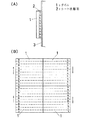
図1(A)(B)は第1実施例の使用状態を示したもので、(A)は壁面に吸着した断面図、(B)は複合タイル4枚の施工における磁極配列状態を示した説明図である。
【0020】
1は市販の窯業系タイル(縦・横・厚さ90×90×8mm)である。2は極間9mmピッチで片面多極着磁した厚さ4mmのシート状磁石で、タイル1と同一寸法に形成され、相対する両端が異極となるように着磁されている。このシート状磁石は等方性バリウムフェライト焼結磁石で、市販の未着磁品をワンターンパルス着磁ヨークにより着磁して用いている。タイル1とシート状磁石2とは、弾性エポキシ系接着剤をタイル裏面にハケで塗布した後4辺を重ね合わせ、室温約20℃に放置して接着し貼り合わせを完成する。
【0021】
3は上記の複合タイルを吸着した被着体で、厚さ0.8mmの塗装鋼板から成る外壁面である。被着体3に吸着した複合タイルは両端に位置する磁極が異極であるため、図1(B)に示すように同一構造のタイルの向きを替えて並列するだけで、異極同士を対応することができ隣接するタイルが自然に吸着しあい複数のタイルを隙間なく並列することができる。
【0022】
磁力のみで吸着する上記複合タイルは施工後も簡単に着脱でき、初心者でも簡単に貼り替えて模様替えすることができる。一方、貼り替えの必要がなく、より強力な固定をするためにはシート状磁石の着磁面側に弾性エポキシ接着剤を塗布し、磁力と接着剤とによって固定する。この場合の接着剤はタイルとシート状磁石の接着に使用したものと同一の接着剤を用いても良い。
【0023】
【実施例2】
実施例2は基本的には実施例1と同一構造である。タイル1は市販の窯業系タイル(縦・横・厚さ90×90×5mm)である。シート状磁石2は厚さ1.5mmで極間3mmピッチの片面多極着磁で、タイル1と同一寸法に形成され、相対する両端が異極となるように着磁されている。
【0024】
このシート状磁石は等方性ストロンチウムフェライト系ゴム磁石で、実施例1と同様の方法で着磁して用いている。タイル1とシート状磁石2とは、それぞれの裏面にフェノール変性ニトリルゴム系接着剤を塗布した後、実施例1と同様に処置して貼り合わせを完成する。実施例1と同様の作用を有する。
【0025】
上記の実施例1及び2ではタイルの裏面全面に磁石を設けたが、タイル裏面の一部、例えば額縁状や相対向する辺に沿った縁部、中央部のみに設けるだけでも同様の作用を得ることができる。
【0026】
【実施例3】
図2(A)(B)は第3実施例を示したもので、(A)は断面図、(B)は平面図である。タイル1は市販の窯業系タイル(縦・横・厚さ90×90×5mm)である。タイル1に貼り合わせたシート状磁石2はタイル1の周囲から3mmの幅で突出し、目地用突出部4を形成している。
【0027】
このシート状磁石は厚さ1.5mm、極間3mmピッチの片面多極着磁で、相対する両端が異極となるように着磁されている。タイル1とシート状磁石2との貼り合わせにはフェノール変性ニトリルゴム系接着剤を塗布した後、実施例1と同様に処置して貼り合わせを完成する。
【0028】
この複合タイルを例えば塗装鋼板外壁面に並列して吸着すると、6mm幅の真っすぐな目地を形成することができ、目地部にタイル1と同じ厚みを有する目地材を嵌め込むことによりタイル1の表面との段差をなくすこともできる。また、図3(A)(B)(C)に示したように、目地用突出部4をタイル1周縁の一部に設けたものを形成することにより、利用範囲の拡大を図ることができる。
【0029】
即ち、互いに隣接する辺の一方のみ目地用突出部4を設けたものを用いて施工すると、3mm幅の目地を形成できる。また、床や壁の端部、目地のない方が都合の良い部分など施工場所に応じて図2及び図3に示した各種のものを使い分けて理想通りの施工をすることができる。
【0030】
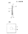
【実施例4】
図4(A)(B)は第4実施例を示したもので、(A)は断面図、(B)は平面図である。タイル1は市販のステンレススチールSUS430を断裁して作成したもので、(縦・横・厚さ)は(100×100×1mm)である。シート状磁石2は異方性ストロンチウムフェライト系ゴム磁石を用い、2.5mmピッチで実施例1と同様に多極着磁用ヨークによって片面着磁したものである。タイル1と同一形状に切断したシート状磁石2の両端磁極は異極にしている。
【0031】
5はタイル1とシート状磁石2とを貼り合わせた接着剤層で、中央に直径約30mmの円状にウレタン系接着剤を塗布している。その後、実施例1と同様に処置し貼り合わせを完了する。
【0032】
この複合タイルを室内壁面、例えば鉄粉60V%を練り込んだ塩素化ポリエチレンシート(厚さ0.8mm)の被着体に貼り付けると、被着面に若干の凹凸があっても、シート状磁石とタイル1とは中央部のみを固定したので、図4(A)の二点鎖線で示したように固定されていない回りの部分を被着面に沿って吸着することができ、磁気吸着力と吸盤作用により複合タイルを固定することができる。複合タイルの貼り替えなど剥がしたいときはシート状磁石の端部から簡単に剥がすことができる。
【0033】
【実施例5】
第5実施例は実施例1と同様にタイルとシート状磁石とを同一形状にしたもので、図1(A)にしたがって説明する。タイル1はビニルタイルで(縦・横・厚さ)が(100×100×5mm)のビニルタイルである。シート状磁石2は極間2.5mmピッチで片面多極着磁したもので、タイル1と同一形状の磁石2は両端が異極となるように磁極配列されている。
【0034】
このシート状磁石2は等方性ストロンチウムフェライト系ゴム磁石で、粘結材としてエチレン酢酸ビニル共重合体エラストマーを非架橋で使用し、公知の方法でシート状磁石としたものである。タイル1とシート状磁石2とはフェノール変性ニトリルゴム系接着剤をタイル1の裏面に塗布し、実施例1と同様に処置し複合タイルを完成する。
【0035】
この複合タイルを厚さ0.8mmのラッカー塗装鋼板から成る外壁面に吸着すると、施工時や施工後数日間は容易に着脱することができるが、施工後、吸着した状態で長時間放置すると、磁石の吸着力とブロッキング現象の進行によって剥がしにくくなり、2週間程度経過すると全面にブロッキング現象が生じ壁面に強力に固定することができる。
【0036】
実施例5に用いたシート状磁石2は粘結材としてエチレン酢酸ビニル共重合体エラストマーを非架橋で使用しているが、エチレン酢酸ビニル共重合体エラストマーに代わるエラストマーとしてアクリルゴム、エチレンプロピレンゴム、塩素化ポリエチレン、クロロスルフォン化ポリエチレンの中のいずれかを用い実施例5と同様に製造したシート状磁石を貼り付けた複合タイルも実施例5と同様の結果が得られた。
【0037】
即ち、前記複合タイル裏面のエラストマーを非架橋で用いたシート状磁石はブロッキング性について、14日後には全面にブロッキングを生じた。しかし、エチレン酢酸ビニル共重合体エラストマーで架橋したシート状磁石を用いた複合タイルは14日程度ではブロッキングを生じず、強力な固定には非架橋がふさわしいことを示している。
【0038】
【発明の効果】
本発明は上記のような構成及び作用を有するので、複合タイルの施工が簡単で未経験者でも並列するだけで完成度の高い施工をすることができ、しかも施工場所に応じた複合タイルを選択して用いることにより模様替え等着脱の容易な貼着と容易にはがせない強力な固定を行うことができる。
【0039】
即ち、裏面のシート状磁石の最初と最後の磁極が異極となるように磁極配置されているタイルは、タイルの向きを変えて貼り付けることにより、異極同士隣接し磁極の異極吸引または同極反発によって、容易に隙間無く目的の位置に貼り付けることができ、また、施工技術を必要としないので目地用磁石突出部を有する場合も同様に並列するだけで、一定幅の目地ができる。
【0040】
施工場所によって必要なときは磁石突出部で形成された目地にタイルの厚みと同等の厚さを有する目地材を埋め込むことによりタイル面と目地との段差を無くすことができる。その上、磁力によって貼り付けているので貼り替えや不要になったときは簡単に剥がすことができる。
【0041】
高所など作業の困難な場所や貼り替えの必要が無く強力な固定力の必要な場所では、強磁性体の被着面と接触する磁石表面側に接着剤層を設けたタイルを用いると、施工中は磁力により仮止めできタイル落下のおそれがなく、安全である。更に、目的の位置に磁気吸着力で保持した後、接着剤の接着力の発現により剥がれないように貼り付けることができる。
【0042】
タイルと可撓性シート状磁石とを中央部でのみ接着したものは被着面に吸着したときに磁力だけでなく吸盤作用が加わり、剥離抵抗が増大し不測の力が加わっても簡単に外れないが、外したいときは磁石の端縁を剥がすようにすると容易に外すことができる。更に、磁石の可撓性によって被着面の凹凸に対しても十分沿うことができ、隙間無く吸着することができる。
【0043】
タイル裏面に、既に列挙したアクリルゴム等を非架橋で使用した有機高分子粘結材を含有した可撓性ボンド磁石を用いることにより、タイル施工時や施工後しばらくの間は着脱が容易にでき、施工後の日数経過に伴って強力な接着を得ることができる。特に被着体の塗装がラッカー塗料、アクリル変性ラッカー塗料又はフタール酸塗料を使用している場合、あるいは被着体表面にゴム系接着剤を塗布乾燥している場合は、日数の経過に従ってブロッキング現象が進行し複合タイルを強力に固定することができる。
【図面の簡単な説明】
【図1】(A)(B)は第1実施例の使用状態を示したもので、(A)は壁面に吸着した断面図、(B)は複合タイル4枚の施工における磁極配列状態を示した説明図。
【図2】(A)(B)は第3実施例を示したもので、(A)は断面図、(B)は平面図。
【図3】(A)(B)(C)は第3実施例において、目地用突出部をタイル周縁の一部に設けた場合の平面図。
【図4】(A)(B)は第4実施例を示したもので、(A)は断面図、(B)は平面図。
【符号の説明】
1 タイル
2 シート状磁石
4 目地用突出部
5 接着剤層[0001]
BACKGROUND OF THE INVENTION
The present invention can be applied in advance to an iron member or an adherend surface having a ferromagnetic surface, and can be used for decoration of a surface material for interior and exterior such as a wall surface and floor surface of a building or a temporary iron member such as a construction site. It relates to composite tiles.
[0002]
[Prior art]
In the past, ceramic tiles such as porcelain tiles that are frequently used for construction are often pasted by plastering using mortar as a bonding material, or after attaching a fixing member for fixing the tile, and corresponding to the insertion part A method of inserting tiles having the shape described above is also employed. In addition to ceramic tiles, there are various tiles such as wooden, synthetic resin, and metal. The sticking method is not limited to mortar, and may be stuck to a wall or floor by other sticking means such as an adhesive.
[0003]
[Problems to be solved by the invention]
In any of the above construction methods, it takes time to apply tiles and perform joint treatment, and skilled craftsmen are required for high-quality finishing, even when fixing tiles made of various materials with adhesives. In order to finish to a certain joint width or to finish a predetermined pattern by combining tiles of various colors and shapes, a laborious work by an expert is required.
[0004]
The present invention eliminates the above-mentioned conventional drawbacks, and can easily apply tiles to the surface of a steel member of a building or an adherend on which a ferromagnetic surface has been formed in advance, without requiring a skilled worker, Depending on the location, so-called Do-it-yourself carpenters can provide tiles that can be changed, and in places where replacement work is difficult or where there is no need for replacement and strong fixation is desired, it can be easily detached during installation. It is intended to provide a composite tile for surface covering that can be applied to the surface and does not easily peel off after completion of the construction and can withstand long-term fixation.
[0005]
[Means for Solving the Problems]
In order to achieve the above object, a composite tile for a cover according to the present invention can be attached to an adherend made of a ferromagnetic material by magnetic adsorption, and the tile and the flexibility provided on the back surface thereof. This sheet magnet is subjected to striped multipolar magnetization arranged so that both ends have different polarities on the surface side in contact with the ferromagnetic adherend. At the same time, the central portion is bonded to the substantially central portion of the back surface of the tile by adhesion so that a sucker action is caused when the ferromagnetic adherend is magnetically attracted and separated .
According to this configuration, since the sheet-like magnet is flexible, stable construction can be performed even if there are slight irregularities on the surface of the adherend.
[0006]
In addition, when the adhesive layer is provided in the adherend side made from a ferromagnetic material , the sheet-like magnet bonded to the tile back surface can be strongly fixed over a long period of time by a magnetic force and an adhesive.
[0007]
Further, it is preferable that the sheet-shaped magnet is protruded by a certain dimension on one side or an arbitrary plurality of sides of the tile periphery because a uniform joint can be easily formed.
[0008]
As a sheet magnet to be bonded to the back of the tile, acrylic rubber, ethylene / propylene rubber, ethylene / propylene non-conjugated diene terpolymer elastomer, ethylene / vinyl acetate copolymer elastomer, chlorinated polyethylene, chlorosulfonated polyethylene When a flexible bonded magnet containing an organic polymer binder using one or more non-crosslinked materials is used, a tile that can withstand long-term fixation can be obtained.
[0009]
[Action]
When the composite tile constructed as described above is applied in parallel with the ferromagnetic surface, the tiles are arranged so that the first and last magnetic poles of the tile sheet magnets are different from each other. By changing the orientation of the magnetic poles, the magnetic poles can be easily attached to the target positions without gaps by adjoining different poles and attracting or repelling the magnetic poles .
[0010]
In addition, since the magnet is flexible, it can be satisfactorily aligned even on an uneven surface, and can be adsorbed without a gap.
Moreover, since not only the magnetic force but also the suction cup action is added, the peeling resistance can be increased.
On the other hand, when it is desired to replace the composite tile or to remove it when it is not needed, it can be done by a simple operation such as peeling off the edge of the magnet.
[0011]
Tiles with an adhesive layer on the surface of the magnet that comes into contact with the ferromagnetic surface need not be replaced and are best used in places where a strong fixing force is required. Since it is attracted to the adherend surface by magnetic force in a place where there is no risk of falling tiles during work, after holding it at the target position with magnetic adsorption force, it can be stuck so that it will not peel off due to the adhesive force of the adhesive it can.
[0012]
A tile with a sheet-shaped magnet that sticks to the back of the tile and protrudes from the edge and has a joint for a joint with a constant width. If a joint is used and only one of adjacent tile edges has a joint protrusion, a narrow joint is obtained. Since the width of the joint protrusions is constant, the work can be completed simply by arranging the tiles in parallel without requiring any technique for tile construction. When it is desired to eliminate the step between the tile surface and the joint projection, the joint is completed by embedding a joint material having a thickness equivalent to the thickness of the tile in the joint formed by the joint projection.
[0013]
As a sheet magnet to be bonded to the back of the tile, acrylic rubber, ethylene / propylene rubber, ethylene / propylene non-conjugated diene terpolymer elastomer, ethylene / vinyl acetate copolymer elastomer, chlorinated polyethylene, chlorosulfonated polyethylene By using a flexible bonded magnet containing an organic polymer binder that uses one or more types of non-cross-linked materials, it can be fixed by reattaching for a while after tile construction or for a while after construction. Strong adhesion can be obtained over time.
[0014]
In particular, when the lacquer paint, acrylic modified lacquer paint or phthalic acid paint is used for the adherend coating, or when a rubber adhesive is applied to the adherend surface and dried, the tile is magnetically adsorbed. As the number of days elapses, a blocking phenomenon, that is, a phenomenon of adhesion by pressing contact for a long time progresses, and a strong adhesion can be obtained.
[0015]
DETAILED DESCRIPTION OF THE INVENTION
In the present invention, tiles and sheet magnets are bonded together. In this case, ceramic tiles (for example, ceramics, glass, cement, etc.), inorganic / organic composite tiles (for example, inorganic powder and a small amount of organic binder) are used. Tiles, metal plates, wood, plastic tiles, etc.) can be used.
[0016]
As the sheet magnets, bonded magnet (e.g., barium ferrite rubber magnet, strontium ferrite rubber magnet, etc.) mainly composed of magnetic material powder and an organic polymer-caking material and the like, can be utilized commercially.
[0017]
As a means for attaching the tile and the sheet-like magnet, an adhesive, a heat fusion welding, a double-sided adhesive tape, an adhesive, or the like can be used, depending on the material of the tile or the magnet. For example, when a material having high rigidity is bonded to each other, a stress due to a difference in impact or thermal expansion coefficient is generated. Therefore, a reactive adhesive having elasticity such as an elastic epoxy adhesive is suitable. When a flexible bonded magnet (rubber magnet) is used, a phenol-modified nitrile rubber-based, phenol-modified chloroprene rubber-based, or urethane-based adhesive is optimal. When the surface property of the tile back surface is inferior, a double-sided pressure-sensitive adhesive tape having a foam as a base material is suitable.
[0018]
Hereinafter, specific embodiments of the present invention will be described with reference to the drawings. In addition, the following Example demonstrates the case where the external shape of a composite tile is a rectangle.
[0019]
[Example 1]
FIGS. 1A and 1B show the state of use of the first embodiment, where FIG. 1A shows a cross-sectional view adsorbed on the wall surface, and FIG. 1B shows the magnetic pole arrangement in the construction of four composite tiles. It is explanatory drawing.
[0020]
1 is a commercially available ceramic tile (length, width, thickness 90 × 90 × 8 mm).
[0021]
3 is an adherend adsorbing the composite tile, and is an outer wall surface made of a coated steel plate having a thickness of 0.8 mm. Since the composite tile adsorbed on the
[0022]
The composite tile adsorbed only by magnetic force can be easily attached and detached even after construction, and even beginners can easily reapply and change the pattern. On the other hand, an elastic epoxy adhesive is applied to the magnetized surface side of the sheet-like magnet and is fixed by a magnetic force and an adhesive in order to fix it more strongly without the need for replacement. In this case, the same adhesive as that used for bonding the tile and the sheet-like magnet may be used.
[0023]
[Example 2]
The second embodiment is basically the same structure as the first embodiment. The
[0024]
This sheet magnet is an isotropic strontium ferrite rubber magnet, which is magnetized and used in the same manner as in Example 1. After the
[0025]
In Examples 1 and 2 described above, the magnet is provided on the entire back surface of the tile. However, the same effect can be obtained only by providing the magnet on only a part of the back surface of the tile, for example, a frame shape or an edge along the opposite side. Obtainable.
[0026]
[Example 3]
2A and 2B show a third embodiment, where FIG. 2A is a cross-sectional view and FIG. 2B is a plan view. The
[0027]
This sheet-like magnet is a single-sided multi-pole magnetized with a thickness of 1.5 mm and a pitch of 3 mm between the poles, and is magnetized so that opposite ends have different polarities. For the bonding of the
[0028]
For example, when this composite tile is adsorbed in parallel to the outer wall surface of a coated steel plate, a straight joint having a width of 6 mm can be formed, and the surface of the
[0029]
That is, when construction is performed using a joint provided with the
[0030]
[Example 4]
4A and 4B show a fourth embodiment, where FIG. 4A is a cross-sectional view and FIG. 4B is a plan view. The
[0031]
[0032]
When this composite tile is attached to an indoor wall, for example, an adherend of a chlorinated polyethylene sheet (thickness 0.8 mm) kneaded with 60 V% of iron powder, even if there is a slight unevenness on the adherend surface, a sheet shape Since only the central part of the magnet and the
[0033]
[Example 5]
In the fifth embodiment, the tile and the sheet-like magnet are formed in the same shape as in the first embodiment, and will be described with reference to FIG. The
[0034]
This sheet-
[0035]
When this composite tile is adsorbed to the outer wall surface made of lacquered steel sheet with a thickness of 0.8 mm, it can be easily detached for several days after construction or after construction. It becomes difficult to peel off due to the attraction force of the magnet and the progress of the blocking phenomenon, and after about 2 weeks, the blocking phenomenon occurs on the entire surface and can be strongly fixed to the wall surface.
[0036]
Although the sheet-
[0037]
That is, the sheet-like magnet using the non-crosslinked elastomer on the back surface of the composite tile was blocked on the entire surface after 14 days. However, composite tiles using sheet magnets cross-linked with ethylene vinyl acetate copolymer elastomer do not block in about 14 days, indicating that non-cross-linking is suitable for strong fixation.
[0038]
【The invention's effect】
Since the present invention has the configuration and operation as described above, it is easy to construct composite tiles, and even an inexperienced person can perform construction with a high degree of completion just by arranging them in parallel. By using it, it is possible to perform sticking that is easy to attach and detach, such as a pattern change, and strong fixing that cannot be easily removed.
[0039]
That is, the tiles arranged in such a manner that the first and last magnetic poles of the sheet magnet on the back surface are different from each other are attached by changing the direction of the tiles, so that the opposite poles are adjacent to each other. The same pole repulsion makes it easy to attach to the target position without any gaps. Also, since construction techniques are not required, joints with a joint width can be formed just by placing them in parallel in the same way even if they have joint protrusions. .
[0040]
When necessary depending on the construction site, a step between the tile surface and the joint can be eliminated by embedding a joint material having a thickness equivalent to the thickness of the tile into the joint formed by the magnet protrusion. In addition, since it is attached by magnetic force, it can be easily removed when it is replaced or no longer needed.
[0041]
In places where it is difficult to work such as high places or where there is no need to replace and there is a need for strong fixing force, using tiles with an adhesive layer on the magnet surface that comes into contact with the ferromagnetic surface, During construction, it can be temporarily fixed by magnetic force, and there is no risk of falling tiles, which is safe. Further, after being held at a target position with a magnetic attraction force, it can be stuck so as not to peel off due to the adhesive force of the adhesive.
[0042]
If the tile and flexible sheet magnet are bonded only at the center, not only the magnetic force but also the suction action acts when adsorbed to the adherend surface, and the peeling resistance increases and even if an unexpected force is applied, it can be easily detached. If you want to remove it, you can easily remove it by peeling off the edge of the magnet. Furthermore, the flexibility of the magnet can sufficiently follow the unevenness of the adherend surface, and can be adsorbed without a gap.
[0043]
By using a flexible bonded magnet containing an organic polymer binder using non-cross-linked acrylic rubber, etc., which has already been enumerated on the back of the tile, it can be easily attached and detached at the time of tile construction and for a while after construction. Strong adhesion can be obtained with the passage of days after construction. Especially when the lacquer paint, acrylic modified lacquer paint or phthalic acid paint is used for the coating of the adherend, or when a rubber adhesive is applied to the adherend surface and dried, the blocking phenomenon occurs over the course of the number of days. Progresses and the composite tile can be strongly fixed.
[Brief description of the drawings]
FIGS. 1A and 1B show the state of use of the first embodiment, where FIG. 1A is a sectional view adsorbed on a wall surface, and FIG. 1B shows the state of magnetic pole arrangement in the construction of four composite tiles. FIG.
FIGS. 2A and 2B show a third embodiment, where FIG. 2A is a cross-sectional view and FIG. 2B is a plan view;
FIGS. 3A, 3B, and 3C are plan views in a case where joint joints are provided on part of the tile periphery in the third embodiment. FIGS.
4A and 4B show a fourth embodiment, where FIG. 4A is a cross-sectional view and FIG. 4B is a plan view.
[Explanation of symbols]
1
Claims (4)
タイルと、その裏面に設けられる可撓性のシート状磁石とで構成され、
該シート状磁石は、上記強磁性体製の被着体と接触する面側に、両端が異極となるように配列された縞状の多極着磁が施されていると共に、その中央部が上記タイルの裏面の略中央部に接着にて貼り合わされていて上記強磁性体製の被着体に磁気吸着させて引き離す時に吸盤作用を生じせしめるものであることを特徴とする表装用複合タイルA composite tile for covering that can be attached to an adherend made of ferromagnetic material by magnetic adsorption,
It is composed of a tile and a flexible sheet magnet provided on the back surface thereof.
The sheet-like magnet is provided with striped multipolar magnetization arranged so that both ends have different polarities on the surface side in contact with the adherend made of the ferromagnetic material, and a central portion thereof. Is attached to the substantially central portion of the back surface of the tile by adhesion, and causes a suction cup action when magnetically attracted to and detached from the adherend made of the ferromagnetic material.
Priority Applications (1)
| Application Number | Priority Date | Filing Date | Title |
|---|---|---|---|
| JP17311099A JP3786801B2 (en) | 1999-05-17 | 1999-05-17 | Composite tile for cover |
Applications Claiming Priority (1)
| Application Number | Priority Date | Filing Date | Title |
|---|---|---|---|
| JP17311099A JP3786801B2 (en) | 1999-05-17 | 1999-05-17 | Composite tile for cover |
Publications (3)
| Publication Number | Publication Date |
|---|---|
| JP2000328759A JP2000328759A (en) | 2000-11-28 |
| JP2000328759A5 JP2000328759A5 (en) | 2004-07-15 |
| JP3786801B2 true JP3786801B2 (en) | 2006-06-14 |
Family
ID=15954355
Family Applications (1)
| Application Number | Title | Priority Date | Filing Date |
|---|---|---|---|
| JP17311099A Expired - Lifetime JP3786801B2 (en) | 1999-05-17 | 1999-05-17 | Composite tile for cover |
Country Status (1)
| Country | Link |
|---|---|
| JP (1) | JP3786801B2 (en) |
Families Citing this family (12)
| Publication number | Priority date | Publication date | Assignee | Title |
|---|---|---|---|---|
| US7464510B2 (en) | 2000-09-19 | 2008-12-16 | Interface, Inc. | System and method for floor covering installation |
| AU2003265409A1 (en) * | 2002-08-15 | 2004-03-03 | Interface, Inc. | Re-configurable modular floor covering |
| US8468772B2 (en) | 2003-08-11 | 2013-06-25 | Interface, Inc. | Carpet tiles and carpet tile installations |
| CN101646737B (en) | 2007-03-27 | 2013-07-17 | 因特菲斯有限公司 | System and method for floor covering installation |
| JP2009057739A (en) * | 2007-08-31 | 2009-03-19 | Toli Corp | Magnetic panel |
| US8394217B2 (en) * | 2010-04-29 | 2013-03-12 | Advance Vinyl Floor Manufacturing Corp. | Method and apparatus for floor planks |
| EP2891746B1 (en) | 2011-05-04 | 2018-10-24 | Tandus Flooring,Inc. | Modular carpet systems |
| JP2015174982A (en) * | 2014-03-18 | 2015-10-05 | ニチレイマグネット株式会社 | Adhesion method of adherend |
| WO2016118797A1 (en) | 2015-01-22 | 2016-07-28 | Interface, Inc. | Floor covering system with sensors |
| WO2020255434A1 (en) * | 2019-06-19 | 2020-12-24 | 株式会社マルチスペース | Wall decoration material and wall decoration material construction method |
| WO2021096543A1 (en) * | 2019-11-16 | 2021-05-20 | Jeremy Britton | Linkable tiles for covering a surface |
| KR102554720B1 (en) * | 2022-11-16 | 2023-07-13 | 이성관 | Tile structure comprising rubber magnet and installation method thereof |
-
1999
- 1999-05-17 JP JP17311099A patent/JP3786801B2/en not_active Expired - Lifetime
Also Published As
| Publication number | Publication date |
|---|---|
| JP2000328759A (en) | 2000-11-28 |
Similar Documents
| Publication | Publication Date | Title |
|---|---|---|
| JP3786801B2 (en) | Composite tile for cover | |
| US5927033A (en) | System for laying wall or floor tiles, or wall or floor plates | |
| US8980426B2 (en) | Peel-and-set tile system | |
| US20150211236A1 (en) | Peel-And-Set Tile System | |
| US5476559A (en) | Magnetic surface-mounting process | |
| US20130269273A1 (en) | Mounting system for decorator tiles | |
| JP4437850B2 (en) | Composite tile | |
| JPH0751339B2 (en) | Composite damping material and vibration damping construction method for vibrating body | |
| US3088588A (en) | Ceramic tile | |
| JPH11172895A (en) | Floor-covering material execution method and floor-covering material thereof | |
| JPH04312671A (en) | Adhesive setting method for facing plate | |
| JP3730902B2 (en) | Display device | |
| WO2008083414A2 (en) | Tiles and mosaics | |
| JP7081912B2 (en) | Wall finishing method | |
| JP2003118294A6 (en) | Display device | |
| JP3390720B2 (en) | Tile adhesive mask | |
| JP2015174982A (en) | Adhesion method of adherend | |
| JP2923205B2 (en) | Construction method of surface unit tile and surface unit tile | |
| JP2000110330A (en) | Floor covering material | |
| JP2001115114A (en) | Decorative laminate temporarily fixing pressure- sensitive double-coated adhesive tape and method of bonding decorative laminate | |
| JP2004324339A (en) | Floor finishing material and execution method therefor | |
| JP2024006837A (en) | Placed tiles | |
| JP2021123932A (en) | Unit tile, and manufacturing method of the same | |
| WO2023164580A2 (en) | Magnetic corner guard | |
| ES2204010T3 (en) | PROCEDURE FOR TREATMENT, ESPECIALLY THE LACQUER OF A SANDWICH. |
Legal Events
| Date | Code | Title | Description |
|---|---|---|---|
| A977 | Report on retrieval |
Free format text: JAPANESE INTERMEDIATE CODE: A971007 Effective date: 20050704 |
|
| A131 | Notification of reasons for refusal |
Free format text: JAPANESE INTERMEDIATE CODE: A131 Effective date: 20050906 |
|
| A521 | Written amendment |
Free format text: JAPANESE INTERMEDIATE CODE: A821 Effective date: 20051104 |
|
| A131 | Notification of reasons for refusal |
Free format text: JAPANESE INTERMEDIATE CODE: A131 Effective date: 20060117 |
|
| A521 | Written amendment |
Free format text: JAPANESE INTERMEDIATE CODE: A523 Effective date: 20060120 |
|
| TRDD | Decision of grant or rejection written | ||
| A01 | Written decision to grant a patent or to grant a registration (utility model) |
Free format text: JAPANESE INTERMEDIATE CODE: A01 Effective date: 20060314 |
|
| A61 | First payment of annual fees (during grant procedure) |
Free format text: JAPANESE INTERMEDIATE CODE: A61 Effective date: 20060322 |
|
| R150 | Certificate of patent or registration of utility model |
Free format text: JAPANESE INTERMEDIATE CODE: R150 |
|
| FPAY | Renewal fee payment (event date is renewal date of database) |
Free format text: PAYMENT UNTIL: 20110331 Year of fee payment: 5 |
|
| FPAY | Renewal fee payment (event date is renewal date of database) |
Free format text: PAYMENT UNTIL: 20130331 Year of fee payment: 7 |
|
| FPAY | Renewal fee payment (event date is renewal date of database) |
Free format text: PAYMENT UNTIL: 20150331 Year of fee payment: 9 |
|
| R250 | Receipt of annual fees |
Free format text: JAPANESE INTERMEDIATE CODE: R250 |
|
| R250 | Receipt of annual fees |
Free format text: JAPANESE INTERMEDIATE CODE: R250 |
|
| R250 | Receipt of annual fees |
Free format text: JAPANESE INTERMEDIATE CODE: R250 |
|
| R250 | Receipt of annual fees |
Free format text: JAPANESE INTERMEDIATE CODE: R250 |
|
| R250 | Receipt of annual fees |
Free format text: JAPANESE INTERMEDIATE CODE: R250 |
|
| EXPY | Cancellation because of completion of term |