JP3786235B2 - Automatic clutch control device for combine - Google Patents
Automatic clutch control device for combine Download PDFInfo
- Publication number
- JP3786235B2 JP3786235B2 JP31946697A JP31946697A JP3786235B2 JP 3786235 B2 JP3786235 B2 JP 3786235B2 JP 31946697 A JP31946697 A JP 31946697A JP 31946697 A JP31946697 A JP 31946697A JP 3786235 B2 JP3786235 B2 JP 3786235B2
- Authority
- JP
- Japan
- Prior art keywords
- cutting
- clutch
- value
- height
- machine body
- Prior art date
- Legal status (The legal status is an assumption and is not a legal conclusion. Google has not performed a legal analysis and makes no representation as to the accuracy of the status listed.)
- Expired - Fee Related
Links
Images


Description
【0001】
【発明の属する技術分野】
本発明は、刈取前処理装置が所定高さより高くなれば刈取前処理装置に動力伝達をON・OFFするための刈取前処理部クラッチをOFFにし、所定高さ以下では前記刈取前処理部クラッチをONにして、刈取り脱穀作業を迅速に実行するようにしたコンバインにおけるオートクラッチ制御装置に関するものである。
【0002】
【従来の技術】
従来から、例えば、特開平7−274650号公報、特開平7−274651号公報等において、刈取前処理装置を所定刈高さまで下降させる刈取脱穀作業時には、自動的に前記刈取前処理部クラッチがONするが、刈取前処理装置を前記刈高さ以上に上昇させる非作業時には自動的に前記刈取前処理部クラッチをOFFするというオートクラッチ制御を実行して、圃場での刈取脱穀作業を迅速に実行することが提案されている。
【0003】
その場合、刈取前処理装置には、その対地高さを検出するための対地高さセンサ(刈高さセンサ)として超音波センサを設け、この検出値に基づいて、前記オートクラッチ制御を実行していた。
【0004】
【発明が解決しようとする課題】
しかしながら、圃場の畦際での刈取脱穀作業の場合には、前記予め設定した刈取高さまで下降させると、刈取前処理装置の側端が畦側面につかえてしまうので、前記設定刈高さより高い位置まで上昇させながら刈取り脱穀させようとしても、前記オートクラッチ制御モードが作動していると、刈取りクラッチが自動的にOFFとなってしまう。
【0005】
また、畦から圃場内に進入しながら、当該畦際の穀稈を刈取脱穀するとき、走行機体が前方下向き傾斜するので、刈取前処理装置の下端が圃場面に衝突しないようにするため、当該刈取前処理装置を走行機体に対して相対的に上昇させた状態にしなければならず、この場合にも前記オートクラッチ制御モードが作動していると、前記刈取前処理部クラッチが自動的にOFFとなってしまうという問題があった。
【0006】
従って、従来の技術では、前記オートクラッチ制御モード(自動モード)を一旦解除して手動モードにより、刈取前処理装置の昇降操作も実行しつつ、同時に走行機体の操縦操作等も手動にて調節しなければならず、極めて操作が煩雑となるという問題があった。
さらに、刈取前処理装置の対地高さを超音波センサにて検出すると、圃場面の条件等により検出結果が不安定となるという問題があった。
【0007】
本発明は、従来のオートクラッチ制御モードによる不具合を解消することを技術的課題とするものである。
【0008】
【課題を解決するための手段】
そのため、請求項1に記載の発明のコンバインにおけるオートクラッチ制御装置は、刈取前処理装置を走行機体に対して油圧シリンダを介して昇降駆動するように構成し、刈取前処理装置と走行機体との対機体昇降位置を検出するための昇降ポジションセンサと、刈取前処理装置の対地高さを検出する非接触式刈高さセンサとを備え、前記昇降ポジションセンサの検出値(Hpx)及び前記非接触式刈高さセンサの検出値(Hsx)に基づいて、刈取前処理装置への動力を継断する刈取前処理部クラッチをON・OFF作動制御するコンバインにおけるオートクラッチ制御装置において、前記刈取前処理部クラッチがONの状態において、前記昇降ポジションセンサの検出値(Hpx)及び前記非接触式刈高さセンサの検出値(Hsx)を適宜時間間隔毎に読み出し、 前記検出値(Hpx)が予め設定された所定値Hph以上であって、且つ、検出値Hsxが目標刈高さ設定値Hsm以上であるときには、刈取前処理部クラッチをOFFとする一方、前記検出値Hsxが前記目標刈高さ設定値Hsmより低い場合または前記検出値(Hpx)が予め設定された所定値Hphより低い場合には、前記刈取前処理部クラッチはONのままに保持されるように制御するものである。
【0009】
【0010】
【0011】
【発明の実施の形態】
次に本発明をコンバインに適用した実施例について説明すると、図1は走行クローラ2aが備えられた左右一対の走行装置2を有するコンバインの走行機体1の側面図、図2は走行機体1の平面図、図3はコンバインの正面図、図4は昇降ポジションセンサの側面図、図5は昇降ポジションセンサの平面図、図6は動力伝達のスケルトン図、図7は油圧回路と制御装置の機能ブロック図である。
【0012】
走行機体1の進行方向に向かって左側には脱穀装置3を搭載し、走行機体1の前部には単動式の油圧シリンダ9により昇降動可能な刈取前処理装置4を配置する。刈取前処理装置4の下部フレームの下部側にはバリカン式の刈刃装置5を、前方には6条分の穀稈引起装置6が配置され、穀稈引起装置6と脱穀装置におけるフイードチェン7前端との間には穀稈搬送装置8が配置され、穀稈引起装置6の下部前方には分草体10が突出している。走行機体1の右側前部に運転室11が配置され、その後側に穀粒タンク12が配置されている。
【0013】
図4及び図5に示すように、刈取前処理装置4に先端を装着した前方下向き傾斜状の昇降筒フレーム14の基端を水平筒15に固着し、該水平筒15を走行機体1の前部に設けた複数の軸受ブラケット16(一方を図示省略)に回動自在に軸支し、走行機体1上のエンジン35からの動力を前記水平筒15及び昇降筒フレーム14の各々の内径部に配置した伝動軸17と19、傘歯車対18等を介して刈取前処理装置4の各部に動力伝達される。そして、昇降筒フレーム14の中途部と走行機体1との間に装架した昇降油圧シリンダ9にて刈取前処理装置4を昇降駆動させるものである。
【0014】
コンバインの動力伝達系を示すスケルトン図(図6)に示すように、エンジン35からの出力の一方は、クラッチ36を介して穀粒タンク12内の底コンベヤ37及び縦コンベヤ38に動力伝達し、次いで排出オーガ28内のスクリューコンベヤ(図示せず)に伝達される。
エンジン35からの他の出力は、動力分岐用ミッション39を介して扱胴駆動軸40、選別駆動軸41、走行用の油圧ポンプ油圧モータ式(HST式)走行駆動部42への駆動軸43及び刈取前処理装置4への定速回転駆動軸44に動力伝達される。そして、扱胴駆動軸40または選別駆動軸41を介して扱胴13及び処理胴29、一番受樋のスクリューコンベヤ26a、唐箕フアン、二番受け樋のスクリューコンベヤ26b及び二番還元コンベヤ25、排藁チェン31、吸引フアン30及び排藁カッタ33に伝達される。
【0015】
他方、前記(HST式)走行駆動部42より出力する刈取同調駆動軸45から、(走行駆動部の正回転時のみ伝達可能な)ワンウエイクラッチ45a及び同調クラッチ46を介して刈取軸47に動力伝達させ、フイードチェン7に直接伝達する。また、刈取軸47に設けた刈取前処理部クラッチ49を介して刈取前処理装置4への動力伝達をON・OFFするように構成されている。それぞれの同調クラッチ46,刈取クラッチ48,刈取前処理部クラッチ49をON・OFF操作するには、それぞれのクラッチに対応する電磁ソレノイド等のクラッチアクチュエータをON・OFF動作するように構成されている。なお、同調クラッチ46はベルトのテンションを緊張・緩和することにより動力継断するテンションクラッチであっても良い。従って、後述するように、車速同調制御を禁止(中止)する場合等で、動力分岐用ミッション39の定速回転駆動軸44を介して刈取軸47に動力伝達し、HST式走行駆動部42より出力する刈取同調駆動軸45の回転数が前記定速回転駆動軸44からの回転数より低い場合や、刈取同調駆動軸45がコンバインの後退方向に回転する場合には、ワンウエイクラッチ45aが空回りする。
【0016】
なお、前記HST式(2油圧モータ2油圧ポンプによる無段階変速機構内に機械的変速機構を組み込んだもの)走行駆動部42の各油圧ポンプ等の斜板を調節して車速を無段階変速するための主変速レバー85は前後回動し、ほぼ垂直姿勢の中立位置(停止位置)に対して前に倒すと前進位置であり、垂直に対する傾斜角度が大きいほど車速が速くなる。後方に傾斜させると後退となり、その傾斜角度が大きいほど車速が速くなる。
【0017】
副変速レバー86は、HST式走行駆動部42内に設けた機械的変速機構(図示せず)を操作する伝動モータ等のアクチュエータを制御するためのものであり、副変速レバーを路上走行モード、標準作業モード、低速作業モードの各位置に切換えると、コンバインに搭載したマイクロコンピュータ式の制御装置(コントローラユニット)70の指令により、前記各作業モード時に適応する走行駆動部42の出力(馬力)及び回転数を所定のレンジに設定保持することができる。
【0018】
なお、走行機体1を前進走行させながら通常の刈取脱穀作業を実行するとき(低速作業モード時及び標準作業モード時)には、動力分岐用ミッション39における刈取クラッチ48をOFF(動力遮断)し、車速の同調クラッチ46及び刈取前処理部クラッチ49はON(動力接続)の状態にし、燃料噴射量センサ及び車速センサの検出値を監視しながら、走行駆動部42の出力に同調させた回転数の刈取同調駆動軸45を介して刈取軸47を駆動させて刈取前処理装置4及びフイードチェン7を同調駆動する一方、扱胴駆動軸40及び選別駆動軸41を駆動させて、扱胴13、処理胴29、送風フアン20、唐箕フアン19、揺動選別機構等を駆動させるのである。
【0019】
また、圃場内での刈取脱穀作業途中において走行機体を方向転換等を実行するに際して、走行機体1を停止または後退させるとき、刈取前処理装置4とフイードチェン7との駆動を停止する時には、同調クラッチ46及び刈取クラッチ48をOFFにする。フイードチェン7のみ駆動するには、刈取前処理部クラッチ49をOFFにする。この場合、刈取前処理装置4への動力伝達はなく、動力分岐用ミッション39から刈取軸47を介してフイードチェン7にのみ動力伝達される。
【0020】
なお、圃場内で、走行機体1を停止させたままで、刈取前処理装置4とフイードチェン7とを駆動させ、刈取前処理装置4の穀稈搬送部に、手で刈取りした穀稈を挿入し、フイードチェン7を介して脱穀部3に持ち込んで脱穀する作業を実行するには、前記走行駆動部42の出力と同調しないように、同調クラッチ46をOFFとする一方、エンジン35からの動力を動力分岐用ミッション39内の脱穀クラッチ48a及び刈取クラッチ48、刈取前処理部クラッチ49を各々電気的にONとする。刈取軸47からフイードチェンクラッチと刈取前処理部クラッチとに二股に分割してフイードチェン7と刈取前処理装置4とに動力伝達するとき、刈取前処理部クラッチモータのON回路とフイードチェンクラッチモータのOFF回路とに各々遅延リレー等の遅延回路を設けることにより、刈取前処理部クラッチより若干早くONさせてフイードチェン7の始動を刈取前処理装置4の始動より早める。逆に作業終了に際して、刈取前処理装置4の停止が早くフイードチェン7の停止が遅いことにより、穀稈の流れを円滑にすることができるのである。
【0021】
刈取前処理装置4と圃場面との対地高さを検出して刈高さを検出するための非接触型刈高さセンサとしての超音波センサ20は、運転室11に近い側の前記穀稈引起装置6の裏面側に設けたブラケット(図示せず)に配置し、図6に示すように、超音波センサ20における発信器20aの発信部(ホーン部)と受信器20bの受信部とを圃場面に向けるように配置する。超音波センサ20の設置高さと刈刃5の設置高さとが異なる場合には、超音波センサ20の検出値から所定の換算により、刈高さ検出値を求めるようにしている。
【0022】
昇降ポジションセンサ22は、走行機体1と刈取前処理装置4との相対高さを検出するためのものであり、本実施例では、図4及び図5に示すように、前記軸受ブラケット16に固定した回動ポテンショメータ式の昇降ポジションセンサ22の感知回動アーム23を、水平筒15の外面に固着したセンサ軸24に当接させ、水平筒15の回動角度θを検出することにより、昇降筒フレーム14の回動角度、ひいては走行機体1に対する刈取前処理装置4の昇降位置(対機体昇降位置)を検出できるようになっている。
【0023】
図7は、刈高さ制御やオートクラッチ制御を実行するための制御装置70の機能ブロック図を示し、該制御装置70は、マイクロコンピュータ等の電子式制御装置であり、図示しないが各種演算処理や制御を実行するための中央処理装置(CPU)や、制御プログラムを記憶させた読み出し専用メモリ(ROM)、各種の検出値、データ等を一時的に記憶させる随時読み書き可能メモリ(RAM)、制御装置の電源をOFFとしても記憶データを保持するための不揮発性メモリ、タイマ機能としてのクロック、インターフェイス、バスなどを備える。
【0024】
超音波センサ20における発信器20aには制御装置70からの指令により発信駆動回路71を介して適宜時間間隔T1にて超音波を発信し、被検出物等にて反射された反射波は受信器20bで受信し、その検出信号は受信増幅回路72を介して制御装置70に入力する。前記昇降ポジションセンサ22の検出信号もA/D変換器を介して前記時間間隔T1ごとに制御装置70に入力する。
【0025】
また、刈高さ設定器73、刈取脱穀作業を手動モードで行うときの手動スイッチ74、同じ作業を自動制御モードにするときの自動スイッチ75、さらに前記手動で実行するとき、刈取前処理装置4を手動にて細かく昇降操作するためのジョイスティック76の各信号もそれぞれ制御装置70に入力される。ジョイスティック76の操作レバーは前後傾動可能で中立位置に自動復帰するように付勢され、操作レバーを前方向に傾倒している間は最小速度で下降継続し、後傾している間は最小速度で上昇継続する。
【0026】
また、前記制御装置70では、後述する所定の演算結果に応じて所定の昇降指令信号を第1駆動回路77と第2駆動回路78とに出力し、第1駆動回路77からの出力に応じて油圧回路79における油圧切換弁80の電磁ソレノイド80a,80bを作動させる一方、第2駆動回路78からの出力に応じて高速応答電磁弁の一例である電磁比例減圧弁50の電磁ソレノイド50aを作動させて、刈取前処理装置4の昇降のための単動油圧シリンダ9を作動させるのである。
【0027】
図7に示す油圧回路79では、前記単動式の昇降油圧シリンダ9及び左右の走行装置2と走行機体1との左右相対車高を制御するための左右一対のローリング制御用油圧シリンダ(図示せず)に対する油圧制御弁51等にも圧油を供給する。
この場合、図7に示すように、油圧回路79の油圧ポンプ52から油圧切換弁49への給油路53中に、リリーフ弁54を介挿する。4ポート3位置切換電磁式の油圧切換弁80の出力ポートから単動油圧シリンダ9への油圧管途中には、逆止弁55、及びスローリターンチェック弁56を接続する。なお、油圧切換弁80の他の出力ポートからは他の油圧制御弁51に同時に給油するように構成されている。
【0028】
前記油圧管の逆止弁55とスローリターンチェック弁56との間に接続した戻油管57には、前記単動油圧シリンダ9のピストンロッド下降用の可変絞り弁58と緊急下降弁59とを並列接続する。この可変絞り弁58は、2ポート2位置切換型のバルブであって、そのパイロットポートには、前記の高速応答電磁弁の1例としての、電磁比例減圧弁50の出力ポートを接続する。
【0029】
そして、刈取前処理装置昇降用の油圧シリンダ9の作動制御は次のように実行する。即ち、電磁式の油圧切換弁80を切換て油圧シリンダ9を伸長させる場合には、電磁ソレノイド80aをパルス幅変調制御(PWM)にて作動させると、電磁比例減圧弁50によって適宜油圧に調整されたパイロット圧が可変絞り弁58に作用し、可変絞り弁58の絞り度合いが任意に変化し、戻油管57から油タンク60にドレンされる。その場合、可変絞り弁58の絞り度合いに応じて油圧シリンダ9の作動速度が調節される。また、油圧シリンダ9を縮小させる場合には、油圧切換弁80を中立にし、電磁比例減圧弁50を前記と同様にパルス幅変調制御(PWM)方式にて作動させ、そのパイロット圧の調節にて可変絞り弁58の絞り開度を調節し、これにより油圧シリンダ9の作動速度を調節する。
【0030】
次に、オートクラッチ制御について説明する。従来の技術のオートクラッチ制御では、刈取前処理装置4を所定の目標刈高さまで下降させる刈取脱穀作業時には、当該刈取前処理装置4に装着した超音波センサにて対地高さを検出し、対地高さが前記目標刈高さより高い位置にきたとき、自動的に刈取前処理部クラッチ49がONになって、刈取前処理装置4にエンジン35からの動力を伝達させて、前記刈取前処理装置4を目標刈高さまで下降させると、刈取脱穀作業を速やかに開始できるようにする。逆に、刈取前処理装置を前記目標刈高さ以上に上昇させる非作業時には、超音波センサ20にて前記目標刈高さより高い位置を検出すると、自動的に刈取前処理部クラッチ49をOFFにさせて、刈取前処理装置4の作動をOFFにするものであった。
【0031】
その場合、超音波センサにて刈取前処理装置4の対地高さを検出すると、圃場面の条件(藁屑による超音波の反射波の乱反射等)により、検出結果が不安定になるという問題があった。
また、圃場の畦際に近い箇所の穀稈を刈取脱穀するとき、目標刈高さが低いと、刈取前処理装置4の側縁等が畦に当接する等の不都合があるので、オペレータが前記目標刈高さより高い位置で刈取前処理装置4の下降を停止し、その状態にて刈取前処理装置4及び脱穀装置3を作動させて刈取脱穀作業を続行させることを希望する事態が発生する。
【0032】
さらに、走行機体1が畦を乗り越えさせて前進しつつ当該畦際の穀稈を刈取脱穀するとき、走行機体の前下向きに傾斜して畦乗り越えすると、前端の刈取前処理装置4を走行機体に対して大きく上昇させていないと、刈取前処理装置4の下端が圃場面に衝突してしまうおそれがあった。
そのため、本発明の第1実施形態では、刈取前処理装置4を走行機体1に対して油圧シリンダ9を介して昇降駆動するように構成し、前記刈取前処理装置4の上昇時に、前記超音波センサ20による刈高さ検出値Hsxが予め設定された設定刈高さ(目標刈高さ設定値Hsm)より高いと判断されると、刈取前処理部クラッチ49がOFFとなるように制御する一方、前記昇降ポジションセンサ22の検出値Hpxが所定値H ph以上であっても、前記目標刈高さ設定値Hsmより前記刈高さ検出値Hsxが低ければ刈取前処理部クラッチ49をOFFとしないように制御することを特徴とする。
【0033】
前記目標刈高さ設定値を決めるための、刈高さ設定器73は、可変抵抗器等のアナログ式であっても良いし、デジタル式であっても良い。刈取前処理装置4の対機体昇降位置の前記所定値Hphの設定に当たっては、別途の初期値設定スイッチ(図示せず)を運転部に設け、オペレータが前記初期値設定スイッチを押下しながら(ON連続時間が適宜秒数以上のとき)、図示しない昇降レバーを操作して刈取前処理装置4を所定の刈高さまで昇降させて停止する。このときの昇降ポジションセンサ22の検出値を所定値Hphとして、制御装置70に備えた不揮発性メモリに格納し、所定のオートクラッチ制御時にこのデータ(所定値Hph)を読出して使用するようにしても良い。
【0034】
図8は本発明のオートクラッチ制御の第1実施形態のフローチャートであって、制御スタートに続き、S1にて刈取前処理部クラッチ49をONにする。次いでS2にて前記所定値Hph及び目標刈高さ設定値Hsmを読み出し、次いで検出値Hpx及び検出値Hsxを適宜時間間隔ΔT1毎に読み出す(S3)。次いで、前記検出値Hpxが所定値Hph以上であるか否かを判別する(S4)。検出値Hpxが所定値Hph以上であるときには(S4:yes )、次いで検出値Hsxが目標刈高さ設定値Hsm以上であるか否かを判別し(S5)、検出値Hsxが目標刈高さ設定値Hsm以上であるときには(S5:yes )、刈取前処理部クラッチ49をOFFとする(S6)。なお、超音波センサ20の検出値Hsxが目標刈高さ設定値Hsmより低い場合(S5:no)、または検出値H px が予め設定された所定値H phより低い場合(S4:no)には、S3の前に戻って判別を繰り返し、前記刈取前処理部クラッチ49はONのままに保持されているのである。
【0035】
これにより、図9に示すように、畦90から圃場91内へコンバインを乗り入れながら、畦際の穀稈を刈取脱穀するときには、走行機体1の前側が高い畦90から圃場91に向かうように前下傾斜する。これにつれて、刈取前処理装置4の下端が圃場90面に急速に接近するので、超音波センサ20にて圃場面を感知し、検出値Hsxは目標刈高さ設定値Hsmより低くなる。そして、刈取前処理装置4の下端が圃場90面に接触しないように油圧シリンダ9を作動させて、当該刈取前処理装置4を上昇させる。すると、略水平な圃場内で通常の刈取脱穀作業時における走行機体1と刈取前処理装置4との対機体高さ(所定値Hph)より高い位置まで上昇していることになるから、前記のオートクラッチ制御において、刈取前処理部クラッチ49をOFFにしない、換言すれば、刈取前処理装置4への動力伝達を実行した状態に保持するから、走行機体1が前下向き傾斜状であっても畦際の穀稈を刈り取ることができるのである。
【0036】
オートクラッチ制御の第2実施形態は、刈取前処理装置4と走行機体1との対機体昇降位置を検出するための昇降ポジションセンサ22と、刈取前処理装置4の対地高さを検出する非接触式刈高さセンサとしての超音波センサ20とを設け、刈高さ設定器73にて予め設定された設定刈高さ(目標刈高さ設定値Hsm)より前記超音波センサ20による刈高さ検出値Hsxが高ければ刈取前処理部クラッチ49がOFFとなるように制御する一方、走行機体1に搭載されたピッチングセンサ92の検出値αにより、前記昇降ポジションセンサ22の検出値Hpxを補正する。また、前記ピッチングセンサ92の検出値αが予め設定された所定値αo以上のときには、前記オートクラッチ制御を実行しない、即ち、刈取前処理部クラッチ49をONのまま保持し、畦乗り入れ時の刈取脱穀作業を可能とするのである。
【0037】
即ち、図9に示すように走行機体1に、当該走行機体1の前後方向の傾斜角度を感知できるピッチングセンサ92を搭載し、ピッチングセンサ92の検出値αを適宜時間間隔にて読取る。この場合、走行機体1が前下がりのとき検出値αは正、後下がりのとき検出値αは負とする。そして、昇降ポジションセンサ22の検出値Hpxを前記検出値αにて補正する。
【0038】
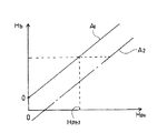
図10に示すように、昇降ポジションセンサ22の検出値Hpxを横軸に採り、縦軸には刈取前処理装置4の先端部(分草体10)の対地高さHb を採る。なぜなら、コンバインを畦90から圃場91内に乗り入れるときには、分草体10の先端が最初に圃場面に接近(衝突)するおそれがあるからである。図10において、直線A1は走行機体1の前後の傾斜がない場合(水平状態)の場合の検出値Hpxに対する対地高さHb の関係を示す。
【0039】
そして、畦90を下る走行機体1が前下がりの傾斜状態では、直線A2のように変化する。即ち、前記直線A1のときに比べて、昇降ポジションセンサ22の検出値Hpxが大きくても、対地高さHb は小さい(刈取前処理装置4の先端部が圃場面91に接近している)ことになる。直線A1とA2とは互いに平行状と仮定すると、
直線A1の関係式: Hb =B・Hpx +K
直線A2の関係式: Hb =B・Hpx +K−f( α)
ここで、B,Kは各々定数であり、f( α) は補正関数である。
【0040】
従って、図10において、走行機体1が水平時の刈取前処理装置4の先端部の対地高さHb1であるとき、直線A1に対する昇降ポジションセンサ22における所定値Hph1 と、直線A2に対する昇降ポジションセンサ22における所定値Hph2 とを比較すると、前記2つの式から、Hph2 =〔Hph1 +f( α) 〕/Bとなる。
【0041】
なお、ピッチングセンサ92の検出値α>所定の設定値αoのとき、即ち走行機体1の前下がり傾斜が急であるときには、さらに刈取前処理装置4の対機体高さを高くした状態であっても、前記オートクラッチ制御を実行しないから、刈取前処理部クラッチ49をONの状態を保持したまま、畦90から圃場91内に乗り入れ、畦際の穀稈を刈取脱穀することができるのである。
【0042】
オートクラッチ制御の第3の実施形態では、刈取前処理装置4を走行機体1に対して油圧シリンダ9を介して昇降駆動するように構成し、刈取前処理装置4と走行機体1との対機体昇降位置を検出するための昇降ポジションセンサ22と、刈取前処理装置4の対地高さを検出する非接触式刈高さセンサとしての超音波センサ20とを設け、予め設定された設定刈高さより前記超音波センサ20による刈高さ検出値が高ければ刈取前処理部クラッチ49がOFFとなるように制御する。一方、前記制御装置70には、前記刈取前処理装置4の手動上昇操作時間Tuを計測し、積算するタイマとメモリとからなる計時手段を設ける。
【0043】
そして、前記計時手段における、前記手動上昇操作時間の累積時間(積算量)は、前記刈取前処理装置4を手動モードもしくは自動モードにて下降するときに出力する下降信号にて0クリアとする。即ち、0クリアにて、メモリに記憶された累積時間(積算量)を零にリセットするのである。前記積算量が所定値以上になれば、前記刈取前処理部クラッチがOFFとなるように制御するものである。
【0044】
このように制御すると、オートクラッチ制御をONにして、図11に示すように圃場91内の未刈り部93の一側縁に沿って1行程93a部分の刈取脱穀した後、未刈り部93の他側縁に沿う1行程93bの始端までコンバインを移動する間は、手動により刈取前処理装置4を圃場面より大きく上昇させるとき、この上昇操作を手動にて実行するので、この間の時間Tuをタイマにて計測し、メモリに積算していく。そして、前記次の1行程93bに入るとき、自動モードもしくは手動モードで、刈取前処理装置4が圃場面に近づくように下降させると、前記メモリに積算されている積算量を0となるようクリアするから、通常の1行程分の刈取脱穀作業中に短い時間だけ刈取前処理装置4を上昇させても、誤って刈取前処理部クラッチ49がOFFにならない。
【0045】
さらに、前記積算量が予め設定された所定値以上になるか、前記昇降ポジションセンサ22による検出値の変化量が一定以上であるか、もしくは超音波センサ20による刈高さ検出値Hsxが刈高さ設定器73にて予め設定された設定刈高さ(目標刈高さ設定値Hsm)より高ければ刈取前処理部クラッチ49がOFFとなるように制御する。
【0046】
これにより、超音波センサ20の検出値のみの判断(超音波センサ20による刈高さ検出値Hsxが刈高さ設定器73にて予め設定された目標刈高さ設定値Hsmより高いか否かの判断)だけにて刈取前処理部クラッチ49をOFFするオートクラッチ制御を実行するよりも安定する制御が実行できるのである。
また、未刈り部93の一側を刈取脱穀して後、当該未刈り部93の他側にコンバインを移動させて刈取・脱穀を続行せる場合、前記時間の積算が少ないときには、刈取前処理装置4側に位置する刈取穀稈をフイードチェン7を介して脱穀部3に送り、脱穀作業も続行することができる一方、1行程から他行程にコンバインの移動中に刈取前処理装置4を設定刈高さ以上に上昇させる時間が長くなると、自動的に刈取前処理部クラッチ49をOFFするので、無駄な動力を消費することも防止でる。
【0047】
【発明の効果】
以上に説明したように、請求項1に記載の発明のコンバインにおけるオートクラッチ制御装置は、刈取前処理装置を走行機体に対して油圧シリンダを介して昇降駆動するように構成し、刈取前処理装置と走行機体との対機体昇降位置を検出するための昇降ポジションセンサと、刈取前処理装置の対地高さを検出する非接触式刈高さセンサとを備え、前記昇降ポジションセンサの検出値(Hpx)及び前記非接触式刈高さセンサの検出値(Hsx)に基づいて、刈取前処理装置への動力を継断する刈取前処理部クラッチをON・OFF作動制御するコンバインにおけるオートクラッチ制御装置において、前記刈取前処理部クラッチがONの状態において、前記昇降ポジションセンサの検出値(Hpx)及び前記非接触式刈高さセンサの検出値(Hsx)を適宜時間間隔毎に読み出し、 前記検出値(Hpx)が予め設定された所定値Hph以上であって、且つ、検出値Hsxが目標刈高さ設定値Hsm以上であるときには、刈取前処理部クラッチをOFFとする一方、前記検出値Hsxが前記目標刈高さ設定値Hsmより低い場合、または前記検出値(Hpx)が予め設定された所定値Hphより低い場合には、前記刈取前処理部クラッチはONのままに保持されるように制御するものである。
【0048】
この構成によれば、畦から圃場内へコンバインを乗り入れながら、畦際の穀稈を刈取脱穀するときには、走行機体の前側が高い畦から圃場に向かうように前下傾斜する。これにつれて、刈取前処理装置の下端が圃場面に急速に接近するので、非接触式刈高さセンサにて圃場面を感知し、非接触式刈高さセンサの検出値は目標刈高さ設定値より低くなる。そして、刈取前処理装置の下端が圃場面に接触しないように油圧シリンダを作動させて、当該刈取前処理装置を上昇させる。すると、略水平な圃場内で通常の刈取脱穀作業時における走行機体と刈取前処理装置との対機体高さ(所定値)より高い位置まで上昇していることになるから、前記のオートクラッチ制御において、刈取前処理部クラッチをOFFにしない、換言すれば、刈取前処理装置への動力伝達を実行した状態に保持するから、走行機体が前下向き傾斜状であっても畦際の穀稈を刈り取ることができるのである。
【0049】
そして、前記検出値Hsxが前記目標刈高さ設定値Hsmより低い場合、または前記検出値(Hpx)が予め設定された所定値Hphより低い場合には、前記刈取前処理部クラッチはONのままに保持されるように制御するものであるので、略水平な圃場内で通常の刈取脱穀作業をそのまま続行できる。
【図面の簡単な説明】
【図1】 コンバインの側面視である。
【図2】 コンバインの平面図である。
【図3】 コンバインの正面図である。
【図4】 ポジションセンサの取付け位置を示す側面図である。
【図5】 ポジションセンサの取付け位置を示す平面図である。
【図6】 動力伝達系統のスケルトン図である。
【図7】 油圧回路及び制御手段の機能ブロック図である。
【図8】 オートクラッチ制御の第1実施形態のフローチャートである。
【図9】 畦乗り入れ時の状態を示す説明図である。
【図10】 オートクラッチ制御の第2実施形態の説明図である。
【図11】 オートクラッチ制御の第3実施形態の説明図である。
【符号の説明】
1 走行機体
2 走行装置
8 刈取前処理装置
9 昇降油圧シリンダ
20 超音波センサ
22 昇降ポジションセンサ
49 刈取前処理部クラッチ
70 制御装置
73 刈高さ設定器
92 ピッチングセンサ[0001]
BACKGROUND OF THE INVENTION
In the present invention, when the pre-cutting processing device becomes higher than a predetermined height, the pre-cutting processing portion clutch for turning ON / OFF the power transmission to the pre-cutting processing device is turned OFF. The present invention relates to an automatic clutch control device in a combine that is turned on and that quickly performs reaping and threshing work.
[0002]
[Prior art]
Conventionally, for example, in Japanese Patent Laid-Open Nos. 7-274650 and 7-274651, the pre-cutting section clutch is automatically turned on at the time of cutting and threshing to lower the pre-cutting processing device to a predetermined cutting height. However, when not working to raise the pre-cutting processing device above the cutting height, auto-clutch control is automatically performed to automatically turn off the pre-cutting processing section clutch, and the cutting and threshing work in the field is quickly executed. It has been proposed to do.
[0003]
In this case, the pre-cutting processing apparatus is provided with an ultrasonic sensor as a ground height sensor (cutting height sensor) for detecting the ground height, and the auto clutch control is executed based on the detected value. It was.
[0004]
[Problems to be solved by the invention]
However, in the case of harvesting and threshing work at the edge of the field, if the lower end is lowered to the preset cutting height, the side end of the pre-cutting device is held on the side of the hook, so that the position is higher than the set cutting height. If the auto-clutch control mode is activated, the mowing clutch is automatically turned off even if the reaping and threshing is attempted.
[0005]
Also, when cutting and threshing the grain culm while entering the field from the reed, the traveling machine body tilts forward and downward, so that the lower end of the pre-harvest processing device does not collide with the field scene. The pre-cutting processing device must be raised relative to the traveling machine body. In this case, if the auto clutch control mode is activated, the pre-cutting processing unit clutch is automatically turned off. There was a problem of becoming.
[0006]
Therefore, in the prior art, the auto clutch control mode (automatic mode) is once canceled and the lifting operation of the pre-cutting processing device is executed in the manual mode, and at the same time, the operation operation of the traveling machine is manually adjusted. There is a problem that the operation is extremely complicated.
Furthermore, when the ground height of the pre-harvest processing device is detected by an ultrasonic sensor, there is a problem that the detection result becomes unstable due to the conditions of the field scene.
[0007]
An object of the present invention is to eliminate the problems caused by the conventional auto clutch control mode.
[0008]
[Means for Solving the Problems]
Therefore, the automatic clutch control device for the combine according to the first aspect of the present invention is configured to drive the cutting pretreatment device up and down via a hydraulic cylinder with respect to the traveling machine body, A lift position sensor for detecting the lift position of the machine body and a non-contact type cutting height sensor for detecting the height of the pre-cutting device for grounding, the detection value (Hpx) of the lift position sensor and the non-contact In the automatic clutch control device for a combine that controls ON / OFF operation of a pre-cutting processing portion clutch that cuts power to the pre-cutting processing device based on a detection value (Hsx) of the type cutting height sensor, the pre-cutting processing Time interval between the detection value (Hpx) of the elevation position sensor and the detection value (Hsx) of the non-contact type cutting height sensor when the clutch is ON When the detected value (Hpx) is not less than a predetermined value Hph that is set in advance and the detected value Hsx is not less than the target cutting height setting value Hsm, the pre-cutting processing section clutch is turned off. When the detected value Hsx is lower than the target cutting height setting value HsmOrWhen the detected value (Hpx) is lower than a predetermined value Hph set in advance, the pre-cutting processing portion clutch is controlled to be kept ON.
[0009]
[0010]
[0011]
DETAILED DESCRIPTION OF THE INVENTION
Next, an embodiment in which the present invention is applied to a combine will be described. FIG. 1 is a side view of a combine
[0012]
A
[0013]
As shown in FIGS. 4 and 5, the base end of the forward and downward inclined
[0014]
As shown in the skeleton diagram (FIG. 6) showing the power transmission system of the combine, one of the outputs from the
Other outputs from the
[0015]
On the other hand, power is transmitted from the
[0016]
The vehicle speed is steplessly changed by adjusting the swash plate of each hydraulic pump or the like of the travel drive unit 42, which is of the HST type (a mechanical transmission mechanism incorporated in a stepless transmission mechanism using two hydraulic motors and two hydraulic pumps). Therefore, the main transmission lever 85 rotates back and forth, and when it is tilted forward with respect to the neutral position (stop position) in a substantially vertical posture, it is the forward movement position, and the vehicle speed increases as the inclination angle with respect to the vertical increases. When the vehicle is tilted backward, the vehicle moves backward, and the vehicle speed increases as the tilt angle increases.
[0017]
The
[0018]
When the normal cutting and threshing operation is performed while the traveling
[0019]
In addition, when the traveling
[0020]
In the field, with the traveling
[0021]
The
[0022]
The
[0023]
FIG. 7 is a functional block diagram of a
[0024]
An ultrasonic wave is transmitted to the
[0025]
Further, the cutting
[0026]
Further, the
[0027]
In the
In this case, as shown in FIG. 7, a
[0028]
A
[0029]
Then, the operation control of the
[0030]
Next, automatic clutch control will be described. In the conventional automatic clutch control, during cutting and threshing work in which the
[0031]
In this case, if the height of the
In addition, when cutting and threshing the grain culm near the vineyard, if the target cutting height is low, there is a problem such as the side edge of the
[0032]
Further, when the traveling
Therefore, in the first embodiment of the present invention, the cutting
[0033]
The cutting
[0034]
FIG. 8 is a flowchart of the first embodiment of the auto clutch control according to the present invention. Following the start of control, the pre-cutting
[0035]
Thus, as shown in FIG. 9, when the harvested culm is cut and threshed while the combine is put into the
[0036]
In the second embodiment of the auto clutch control, the
[0037]
That is, as shown in FIG. 9, the traveling
[0038]
As shown in FIG. 10, the detection value Hpx of the
[0039]
Then, when the traveling
Relational expression of straight line A1: Hb = B · Hpx + K
Relational expression of the straight line A2: Hb = B · Hpx + K−f (α)
Here, B and K are constants, and f (α) is a correction function.
[0040]
Accordingly, in FIG. 10, when the traveling
[0041]
When the detected value α of the pitching
[0042]
In the third embodiment of the auto clutch control, the
[0043]
The accumulated time (integrated amount) of the manual ascent operation time in the time measuring means is cleared to 0 by a descending signal output when the
[0044]
When controlled in this way, the automatic clutch control is turned on, and one
[0045]
Further, whether the integrated amount is greater than or equal to a predetermined value set in advance, the amount of change in the detected value by the
[0046]
Thereby, only the detection value of the
In addition, after cutting and threshing one side of the
[0047]
【The invention's effect】
As described above, the automatic clutch control device for the combine according to the first aspect of the present invention is configured to drive the cutting pre-treatment device up and down with respect to the traveling machine body via the hydraulic cylinder, and the cutting pre-treatment device. The lift position sensor for detecting the lift position of the machine body and the traveling machine body, and the non-contact type cutting height sensor for detecting the ground height of the pre-cutting device, the detected value (Hpx ) And a non-contact cutting height sensor detection value (Hsx), an automatic clutch control device in a combine that performs ON / OFF operation control of a pre-cutting section clutch that cuts power to the pre-cutting processing apparatus. In the state where the pre-cutting section clutch is ON, the detected value (Hpx) of the lift position sensor and the detected value (Hsx) of the non-contact type cutting height sensor Read at appropriate time intervals, and when the detected value (Hpx) is equal to or greater than a predetermined value Hph that is set in advance and the detected value Hsx is equal to or greater than the target cutting height set value Hsm, When the detection value Hsx is lower than the target cutting height setting value Hsm while turning OFFOrWhen the detected value (Hpx) is lower than a predetermined value Hph set in advance, the pre-cutting processing portion clutch is controlled to be kept ON.
[0048]
According to this configuration, when the harvested culm is harvested and threshed while the combine is put into the field from the cocoon, the front side of the traveling machine body is inclined forward and downward so as to go from the high cocoon to the field. Along with this, the lower end of the cutting pretreatment device approaches the field scene rapidly, so the field scene is sensed by the non-contact type cutting height sensor, and the detected value of the non-contact type cutting height sensor is set to the target cutting height. Lower than the value. Then, the hydraulic cylinder is operated so that the lower end of the pre-cutting processing device does not contact the field scene, and the pre-cutting processing device is raised. Then, in the substantially horizontal field, the above-described auto clutch control is performed because the vehicle body is raised to a position higher than the machine body height (predetermined value) between the traveling machine body and the cutting pretreatment device during normal cutting and threshing work. In this case, the pre-cutting section clutch is not turned off, in other words, the power transmission to the pre-cutting processing device is held, so that the crushed rice cake can be removed even when the traveling machine body is inclined forward and downward. It can be reaped.
[0049]
When the detected value Hsx is lower than the target cutting height setting value HsmOrWhen the detected value (Hpx) is lower than a predetermined value Hph set in advance, the pre-cutting section clutch is controlled to be kept ON. The mowing and threshing work can be continued as it is.
[Brief description of the drawings]
FIG. 1 is a side view of a combine.
FIG. 2 is a plan view of the combine.
FIG. 3 is a front view of the combine.
FIG. 4 is a side view showing an attachment position of the position sensor.
FIG. 5 is a plan view showing an attachment position of a position sensor.
FIG. 6 is a skeleton diagram of a power transmission system.
FIG. 7 is a functional block diagram of a hydraulic circuit and control means.
FIG. 8 is a flowchart of the first embodiment of auto clutch control.
FIG. 9 is an explanatory view showing a state when entering a saddle.
FIG. 10 is an explanatory diagram of a second embodiment of auto clutch control.
FIG. 11 is an explanatory diagram of a third embodiment of auto clutch control.
[Explanation of symbols]
1 Airframe
2 Traveling device
8 Pre-cutting device
9 Lifting hydraulic cylinder
20 Ultrasonic sensor
22 Lift position sensor
49 Pre-cutting section clutch
70 Controller
73 Cutting height setter
92 Pitching sensor
Claims (1)
前記刈取前処理部クラッチがONの状態において、前記昇降ポジションセンサの検出値(Hpx)及び前記非接触式刈高さセンサの検出値(Hsx)を適宜時間間隔毎に読み出し、
前記検出値(Hpx)が予め設定された所定値Hph以上であって、且つ、検出値Hsxが目標刈高さ設定値Hsm以上であるときには、刈取前処理部クラッチをOFFとする一方、
前記検出値Hsxが前記目標刈高さ設定値Hsmより低い場合または前記検出値(Hpx)が予め設定された所定値Hphより低い場合には、前記刈取前処理部クラッチはONのままに保持されるように制御することを特徴とするコンバインにおけるオートクラッチ制御装置。The cutting pre-treatment device is configured to be driven up and down with respect to the traveling machine body via a hydraulic cylinder, and a lifting position sensor for detecting a machine lifting position between the cutting pre-treatment device and the traveling machine body, and a cutting pre-processing device. A non-contact cutting height sensor for detecting the height of the ground, and pre-cutting processing based on the detection value (Hpx) of the lift position sensor and the detection value (Hsx) of the non-contact cutting height sensor In an automatic clutch control device in a combine that controls ON / OFF operation of a pre-cutting clutch that cuts power to the device,
When the pre-cutting section clutch is in an ON state, the detection value (Hpx) of the elevation position sensor and the detection value (Hsx) of the non-contact type cutting height sensor are read at appropriate time intervals,
When the detected value (Hpx) is not less than a predetermined value Hph that is set in advance and the detected value Hsx is not less than the target cutting height setting value Hsm,
When the detected value Hsx is lower than the target cutting height set value Hsm or when the detected value (Hpx) is lower than a predetermined value Hph, the pre-cutting processing section clutch is kept ON. An automatic clutch control device for a combine, wherein
Priority Applications (1)
| Application Number | Priority Date | Filing Date | Title |
|---|---|---|---|
| JP31946697A JP3786235B2 (en) | 1997-11-20 | 1997-11-20 | Automatic clutch control device for combine |
Applications Claiming Priority (1)
| Application Number | Priority Date | Filing Date | Title |
|---|---|---|---|
| JP31946697A JP3786235B2 (en) | 1997-11-20 | 1997-11-20 | Automatic clutch control device for combine |
Related Child Applications (1)
| Application Number | Title | Priority Date | Filing Date |
|---|---|---|---|
| JP2005313627A Division JP2006051044A (en) | 2005-10-28 | 2005-10-28 | Automatic clutch controller in combine harvester |
Publications (2)
| Publication Number | Publication Date |
|---|---|
| JPH11151015A JPH11151015A (en) | 1999-06-08 |
| JP3786235B2 true JP3786235B2 (en) | 2006-06-14 |
Family
ID=18110525
Family Applications (1)
| Application Number | Title | Priority Date | Filing Date |
|---|---|---|---|
| JP31946697A Expired - Fee Related JP3786235B2 (en) | 1997-11-20 | 1997-11-20 | Automatic clutch control device for combine |
Country Status (1)
| Country | Link |
|---|---|
| JP (1) | JP3786235B2 (en) |
Families Citing this family (2)
| Publication number | Priority date | Publication date | Assignee | Title |
|---|---|---|---|---|
| CN103444347B (en) * | 2013-08-08 | 2016-03-02 | 农业部南京农业机械化研究所 | A kind of Automatic depth limiter of peanut combine harvester |
| JP6320314B2 (en) * | 2015-02-06 | 2018-05-09 | ヤンマー株式会社 | Combine transmission structure |
-
1997
- 1997-11-20 JP JP31946697A patent/JP3786235B2/en not_active Expired - Fee Related
Also Published As
| Publication number | Publication date |
|---|---|
| JPH11151015A (en) | 1999-06-08 |
Similar Documents
| Publication | Publication Date | Title |
|---|---|---|
| JP3786235B2 (en) | Automatic clutch control device for combine | |
| JP3657357B2 (en) | Combine | |
| JP3881000B2 (en) | Lifting / driving control device for harvesting pretreatment device in combine | |
| JP2855426B2 (en) | Combine | |
| JP2006051044A (en) | Automatic clutch controller in combine harvester | |
| JP3689187B2 (en) | Combine | |
| JP3720553B2 (en) | Cutting height control device for combine | |
| JP3880971B2 (en) | Combine | |
| JP3720528B2 (en) | Cutting height control device for combine | |
| JP3880972B2 (en) | Combine | |
| JP3985008B2 (en) | Drive control device for harvesting pretreatment device in combine | |
| JP7206176B2 (en) | agricultural vehicle | |
| JP6941304B2 (en) | combine | |
| JPH11168936A (en) | Reaping height controller of combine harvester | |
| JPH11151016A (en) | Automatic clutch control part for combine harvester | |
| JPH11285310A (en) | Driving controller for reaping pretreatment device in combine harvester | |
| JPH11146717A (en) | Reaping height control unit in combine harvester | |
| JPH1042647A (en) | Lifting and lowering control apparatus for reaping pretreating apparatus in combine harvester | |
| JP3859854B2 (en) | Combine | |
| JPH10304724A (en) | Cutting height controller for combine | |
| JP2006075113A (en) | Combine harvester | |
| JPH11168935A (en) | Reaping height controller of combine harvester | |
| JP2962079B2 (en) | Combine cutting height control device | |
| JPH10304723A (en) | Elevating/lowering and driving controller of cutting pre-treating device for combine | |
| JP3604318B2 (en) | Work machine lifting control |
Legal Events
| Date | Code | Title | Description |
|---|---|---|---|
| A977 | Report on retrieval |
Free format text: JAPANESE INTERMEDIATE CODE: A971007 Effective date: 20050303 |
|
| A131 | Notification of reasons for refusal |
Free format text: JAPANESE INTERMEDIATE CODE: A131 Effective date: 20050322 |
|
| A521 | Written amendment |
Free format text: JAPANESE INTERMEDIATE CODE: A523 Effective date: 20050523 |
|
| A131 | Notification of reasons for refusal |
Free format text: JAPANESE INTERMEDIATE CODE: A131 Effective date: 20050830 |
|
| A521 | Written amendment |
Free format text: JAPANESE INTERMEDIATE CODE: A523 Effective date: 20051028 |
|
| TRDD | Decision of grant or rejection written | ||
| A01 | Written decision to grant a patent or to grant a registration (utility model) |
Free format text: JAPANESE INTERMEDIATE CODE: A01 Effective date: 20060314 |
|
| A61 | First payment of annual fees (during grant procedure) |
Free format text: JAPANESE INTERMEDIATE CODE: A61 Effective date: 20060315 |
|
| FPAY | Renewal fee payment (event date is renewal date of database) |
Free format text: PAYMENT UNTIL: 20090331 Year of fee payment: 3 |
|
| FPAY | Renewal fee payment (event date is renewal date of database) |
Free format text: PAYMENT UNTIL: 20100331 Year of fee payment: 4 |
|
| LAPS | Cancellation because of no payment of annual fees |