JP3782289B2 - Method of processing shape memory alloy and shape memory alloy - Google Patents
Method of processing shape memory alloy and shape memory alloy Download PDFInfo
- Publication number
- JP3782289B2 JP3782289B2 JP2000204927A JP2000204927A JP3782289B2 JP 3782289 B2 JP3782289 B2 JP 3782289B2 JP 2000204927 A JP2000204927 A JP 2000204927A JP 2000204927 A JP2000204927 A JP 2000204927A JP 3782289 B2 JP3782289 B2 JP 3782289B2
- Authority
- JP
- Japan
- Prior art keywords
- shape memory
- memory alloy
- stress
- temperature
- movement
- Prior art date
- Legal status (The legal status is an assumption and is not a legal conclusion. Google has not performed a legal analysis and makes no representation as to the accuracy of the status listed.)
- Expired - Fee Related
Links
- 229910001285 shape-memory alloy Inorganic materials 0.000 title claims description 236
- 238000000034 method Methods 0.000 title claims description 91
- 238000012545 processing Methods 0.000 title claims description 46
- 239000013078 crystal Substances 0.000 claims description 207
- 230000033001 locomotion Effects 0.000 claims description 111
- 239000000956 alloy Substances 0.000 claims description 82
- 230000008569 process Effects 0.000 claims description 60
- 238000001953 recrystallisation Methods 0.000 claims description 44
- 238000010438 heat treatment Methods 0.000 claims description 41
- 238000011084 recovery Methods 0.000 claims description 35
- 229910000734 martensite Inorganic materials 0.000 claims description 33
- 230000002441 reversible effect Effects 0.000 claims description 33
- 230000009466 transformation Effects 0.000 claims description 31
- 229910001566 austenite Inorganic materials 0.000 claims description 29
- 238000003672 processing method Methods 0.000 claims description 20
- 238000001816 cooling Methods 0.000 claims description 19
- 230000000452 restraining effect Effects 0.000 claims description 17
- 238000005482 strain hardening Methods 0.000 claims description 16
- 229910018054 Ni-Cu Inorganic materials 0.000 claims description 14
- 229910018481 Ni—Cu Inorganic materials 0.000 claims description 14
- 229910004337 Ti-Ni Inorganic materials 0.000 claims description 12
- 229910011209 Ti—Ni Inorganic materials 0.000 claims description 12
- KHYBPSFKEHXSLX-UHFFFAOYSA-N iminotitanium Chemical compound [Ti]=N KHYBPSFKEHXSLX-UHFFFAOYSA-N 0.000 claims description 12
- 229910045601 alloy Inorganic materials 0.000 claims description 11
- 229910000765 intermetallic Inorganic materials 0.000 claims description 5
- 239000000463 material Substances 0.000 description 82
- 230000003446 memory effect Effects 0.000 description 32
- 230000000694 effects Effects 0.000 description 15
- 230000002457 bidirectional effect Effects 0.000 description 14
- IJGRMHOSHXDMSA-UHFFFAOYSA-N Atomic nitrogen Chemical compound N#N IJGRMHOSHXDMSA-UHFFFAOYSA-N 0.000 description 12
- 238000012360 testing method Methods 0.000 description 12
- 238000005452 bending Methods 0.000 description 8
- 230000008859 change Effects 0.000 description 8
- 239000012535 impurity Substances 0.000 description 8
- 239000011162 core material Substances 0.000 description 7
- 229910052757 nitrogen Inorganic materials 0.000 description 7
- 238000010586 diagram Methods 0.000 description 6
- 239000007788 liquid Substances 0.000 description 6
- 229910052751 metal Inorganic materials 0.000 description 6
- 239000002184 metal Substances 0.000 description 6
- 238000005259 measurement Methods 0.000 description 5
- 239000000203 mixture Substances 0.000 description 5
- 238000001556 precipitation Methods 0.000 description 5
- 230000004043 responsiveness Effects 0.000 description 5
- 238000006243 chemical reaction Methods 0.000 description 4
- 230000007423 decrease Effects 0.000 description 4
- 239000002994 raw material Substances 0.000 description 4
- 230000008707 rearrangement Effects 0.000 description 4
- 230000003252 repetitive effect Effects 0.000 description 4
- FFBHFFJDDLITSX-UHFFFAOYSA-N benzyl N-[2-hydroxy-4-(3-oxomorpholin-4-yl)phenyl]carbamate Chemical compound OC1=C(NC(=O)OCC2=CC=CC=C2)C=CC(=C1)N1CCOCC1=O FFBHFFJDDLITSX-UHFFFAOYSA-N 0.000 description 3
- 239000003574 free electron Substances 0.000 description 3
- 230000006870 function Effects 0.000 description 3
- 230000000704 physical effect Effects 0.000 description 3
- 238000002360 preparation method Methods 0.000 description 3
- 230000009467 reduction Effects 0.000 description 3
- 238000012549 training Methods 0.000 description 3
- OKTJSMMVPCPJKN-UHFFFAOYSA-N Carbon Chemical compound [C] OKTJSMMVPCPJKN-UHFFFAOYSA-N 0.000 description 2
- XEEYBQQBJWHFJM-UHFFFAOYSA-N Iron Chemical group [Fe] XEEYBQQBJWHFJM-UHFFFAOYSA-N 0.000 description 2
- 230000008901 benefit Effects 0.000 description 2
- 229910052799 carbon Inorganic materials 0.000 description 2
- 238000005097 cold rolling Methods 0.000 description 2
- 238000009792 diffusion process Methods 0.000 description 2
- 238000006073 displacement reaction Methods 0.000 description 2
- 230000002829 reductive effect Effects 0.000 description 2
- 230000000717 retained effect Effects 0.000 description 2
- 238000004804 winding Methods 0.000 description 2
- 208000000044 Amnesia Diseases 0.000 description 1
- CXHUZKJFWQGUJG-UHFFFAOYSA-N CC1(CCCC2)C2CCCCC1 Chemical compound CC1(CCCC2)C2CCCCC1 CXHUZKJFWQGUJG-UHFFFAOYSA-N 0.000 description 1
- CURLTUGMZLYLDI-UHFFFAOYSA-N Carbon dioxide Chemical compound O=C=O CURLTUGMZLYLDI-UHFFFAOYSA-N 0.000 description 1
- 241001391944 Commicarpus scandens Species 0.000 description 1
- 239000008186 active pharmaceutical agent Substances 0.000 description 1
- 238000000137 annealing Methods 0.000 description 1
- 230000004888 barrier function Effects 0.000 description 1
- 230000006399 behavior Effects 0.000 description 1
- 230000015572 biosynthetic process Effects 0.000 description 1
- 238000005422 blasting Methods 0.000 description 1
- 235000011089 carbon dioxide Nutrition 0.000 description 1
- 238000005266 casting Methods 0.000 description 1
- 239000000919 ceramic Substances 0.000 description 1
- -1 ceramics Chemical class 0.000 description 1
- 230000006835 compression Effects 0.000 description 1
- 238000007906 compression Methods 0.000 description 1
- 239000002178 crystalline material Substances 0.000 description 1
- 230000003247 decreasing effect Effects 0.000 description 1
- 230000007547 defect Effects 0.000 description 1
- 230000008034 disappearance Effects 0.000 description 1
- 230000001747 exhibiting effect Effects 0.000 description 1
- 230000004927 fusion Effects 0.000 description 1
- 230000001771 impaired effect Effects 0.000 description 1
- 230000006872 improvement Effects 0.000 description 1
- 150000002484 inorganic compounds Chemical class 0.000 description 1
- 229910010272 inorganic material Inorganic materials 0.000 description 1
- 229910052742 iron Inorganic materials 0.000 description 1
- 230000002427 irreversible effect Effects 0.000 description 1
- 231100000863 loss of memory Toxicity 0.000 description 1
- 238000003754 machining Methods 0.000 description 1
- 238000004519 manufacturing process Methods 0.000 description 1
- 230000007246 mechanism Effects 0.000 description 1
- 239000007769 metal material Substances 0.000 description 1
- 150000002739 metals Chemical class 0.000 description 1
- 210000003205 muscle Anatomy 0.000 description 1
- 230000008520 organization Effects 0.000 description 1
- 230000036961 partial effect Effects 0.000 description 1
- 238000007747 plating Methods 0.000 description 1
- 230000002040 relaxant effect Effects 0.000 description 1
- 230000008521 reorganization Effects 0.000 description 1
- 238000011160 research Methods 0.000 description 1
- 238000007665 sagging Methods 0.000 description 1
- 238000007711 solidification Methods 0.000 description 1
- 230000008023 solidification Effects 0.000 description 1
- 230000007480 spreading Effects 0.000 description 1
- 238000003892 spreading Methods 0.000 description 1
- 238000004544 sputter deposition Methods 0.000 description 1
- 230000007847 structural defect Effects 0.000 description 1
- 239000000126 substance Substances 0.000 description 1
- 238000004781 supercooling Methods 0.000 description 1
- 230000002459 sustained effect Effects 0.000 description 1
Images


Classifications
-
- C—CHEMISTRY; METALLURGY
- C22—METALLURGY; FERROUS OR NON-FERROUS ALLOYS; TREATMENT OF ALLOYS OR NON-FERROUS METALS
- C22F—CHANGING THE PHYSICAL STRUCTURE OF NON-FERROUS METALS AND NON-FERROUS ALLOYS
- C22F1/00—Changing the physical structure of non-ferrous metals or alloys by heat treatment or by hot or cold working
- C22F1/006—Resulting in heat recoverable alloys with a memory effect
-
- C—CHEMISTRY; METALLURGY
- C22—METALLURGY; FERROUS OR NON-FERROUS ALLOYS; TREATMENT OF ALLOYS OR NON-FERROUS METALS
- C22F—CHANGING THE PHYSICAL STRUCTURE OF NON-FERROUS METALS AND NON-FERROUS ALLOYS
- C22F1/00—Changing the physical structure of non-ferrous metals or alloys by heat treatment or by hot or cold working
- C22F1/10—Changing the physical structure of non-ferrous metals or alloys by heat treatment or by hot or cold working of nickel or cobalt or alloys based thereon
Landscapes
- Chemical & Material Sciences (AREA)
- Physics & Mathematics (AREA)
- Thermal Sciences (AREA)
- Crystallography & Structural Chemistry (AREA)
- Engineering & Computer Science (AREA)
- Materials Engineering (AREA)
- Mechanical Engineering (AREA)
- Metallurgy (AREA)
- Organic Chemistry (AREA)
- Heat Treatment Of Steel (AREA)
- Micromachines (AREA)
- Springs (AREA)
Description
【0001】
【発明の属する技術分野】
本発明は、アクチュエータ(駆動装置)用として用いるに好適な形状記憶合金および該形状記憶合金を得るための形状記憶合金の処理方法に関する。
【0002】
【従来の技術】
従来、一般に、形状記憶合金素材を使用に適した特性を有するように処理する際、結晶粒を微細化したり、結晶粒の方位を調整することは行われていなかった。
【0003】
一方、形状記憶合金を利用するためには所定の形状を記憶させる必要があり、このためにはそれぞれの合金に特有の熱処理をする必要がある。従来、この熱処理は、「形状記憶処理」と呼ばれているが、非常に微妙な処理であるから、厳密に条件を管理することが必要である。例えば、従来よりよく行われている一般的なTi−Ni系合金の形状記憶処理方法としては、形状記憶合金をあらかじめ十分に加工硬化させた上で、所定の形状に加工し、そのままの形に固定して400〜500℃の温度で、数分〜数時間置く方法(中温処理と呼ばれている)や、800℃以上の温度にしばらく置いた後、急冷し、所定の形状に加工して、これを200〜300℃の比較的低い温度で保持する方法(低温処理と呼ばれている)等があった(参考文献:工業調査会発行、石川昇二、木梨貞男、三輪学編著、「図解最新特許に見る形状記憶合金応用アイデア集」)。
【0004】
【発明が解決しようとする課題】
従来の一般的な形状記憶合金をアクチュエータとして用いる際には、主として次のような欠点があった。
【0005】
(a)応答性(速度)が悪い、
(b)Ms、Mf点を上げにくいため、使用可能な温度域が限定される、
(c)有効に取り出せる力が小さい、
(d)破断に至るまでの寿命が短い、
(e)短期間のうちに記憶形状の消失や永久ひずみが発生しやすい、
(f)短期間のうちに運動として取り出せるひずみ(以後運動ひずみという)が減少する、
(g)Ti−Ni系、Ti−Ni−Cu系等の、金属間化合物として共有結合性が強い難加工性の形状記憶合金素材の場合、組成によっては、特に脆性が強くなり、割れやすいため、利用が困難である、
このような問題点があるため、従来は、形状記憶合金の用途の8割ないしは9割以上は超弾性ばね材としての利用であり、残り僅かがアクチュエータとしての用途であった。しかも、アクチュエータ用途の形状記憶合金の大半は、コイルばね、線材または板材の形状とされた上、曲げ変形またはねじりおよび曲げ変形からの形状回復を利用していた(コイルばね形状の場合、巨視的には、形状記憶合金は伸縮するが、真の意味では、その変形はねじりおよび曲げ変形である)。このように曲げ変形またはねじりおよび曲げ変形からの形状回復を利用して使用する理由は、従来の一般的な形状記憶合金は安定に利用できる形状記憶効果の範囲が非常に小さいため、この小さなひずみが増幅されるような形態で使用しなければならぬからであった。従来の一般的な形状記憶合金の運動ひずみは、引っ張りひずみ換算で最大数%から10%近いと言われているが、これは、1〜数回の動作の話で、実際には変形と形状回復を繰り返すと運動ひずみも減少し、記憶形状を失い、最終的には破断していた。
【0006】
また、前記従来の一般的なTi−Ni系合金の形状記憶処理方法は、いずれの方法も、加工硬化によって強化された組織の中に部分的に形状記憶効果や超弾性を発生できる組織を生じさせることにより、形状の安定性を保つと同時に超弾性や形状記憶効果を得ようとするものである。言い換えれば、形状の安定性を得るために超弾性や形状記憶効果をある程度犠牲にせざる終えない処理であった。
【0007】
他方、本発明者は、前に特開昭63−240939号において、多結晶体に変態温度区間を含む加熱過程と冷却過程とを備えた熱サイクルを与えるとともに、この熱サイクルの少なくとも一部に重ねて、前記多結晶体に方向性を有するエネルギ場を作用させることを特徴とする多結晶体の結晶方位再配列方法を提案した。この多結晶体の結晶方位再配列方法を形状記憶合金に適用すると、前記従来の一般的な形状記憶合金の欠点を飛躍的に改善することができる。
【0008】
しかしながら、この結晶方位再配列方法においては、形状記憶合金に適用する場合、結晶粒の微細化を行わず、むしろ結晶を成長させて大きくしていた。また、形状記憶合金素材の結晶の方向を揃える最終過程において引張力等を作用させることにより、最終的に得られる形状記憶合金の組織を壊してしまう面があった。このため、前記従来の一般的な形状記憶合金の問題を解決する上で、やや不十分な面があった。
【0009】
本発明は、このような従来の事情に鑑みてなされたもので、本発明の1つの目的は、応答性のよい形状記憶合金および該形状記憶合金を得るための形状記憶合金の処理方法を提供することにある。
【0010】
本発明のさらに他の目的は、使用可能な温度域が広い形状記憶合金および該形状記憶合金を得るための形状記憶合金の処理方法を提供することにある。
【0011】
本発明のさらに他の目的は、実用的に有効に取り出せる力が大きい形状記憶合金および該形状記憶合金を得るための形状記憶合金の処理方法を提供することにある。
【0012】
本発明のさらに他の目的は、繰り返し大きな運動ひずみが取り出せる形状記憶合金および該形状記憶合金を得るための形状記憶合金の処理方法を提供することにある。
【0013】
本発明のさらに他の目的は、巨大な双方向性形状記憶効果を持つ形状記憶合金および該形状記憶合金を得るための形状記憶合金の処理方法を提供することにある。
【0014】
本発明のさらに他の目的は、破断に至るまでの寿命が長い形状記憶合金および該形状記憶合金を得るための形状記憶合金の処理方法を提供することにある。
【0015】
本発明のさらに他の目的は、記憶形状が消失しにくい形状記憶合金および該形状記憶合金を得るための形状記憶合金の処理方法を提供することにある。
【0016】
本発明のさらに他の目的は、運動ひずみの減少が少ない形状記憶合金および該形状記憶合金を得るための形状記憶合金の処理方法を提供することにある。
【0017】
本発明のさらに他の目的は、前記の種々の優れた特性が長期多数回にわたる繰り返しにおいても安定している形状記憶合金および該形状記憶合金を得るための形状記憶合金の処理方法を提供することにある。
【0018】
本発明のさらに他の目的は、これまで脆性が強く、割れやすいため利用が困難とされていた材料をも素材として用い、靱性を持った線材や板材状の形状記憶合金とすることができる形状記憶合金の処理方法を提供することにある。
【0019】
本発明のさらに他の目的は、形状記憶合金の組織を壊すことなく、結晶の方向を揃えることができる形状記憶合金の処理方法を提供することにある。
【0020】
本発明のさらに他の目的は、以下の説明から明らかになろう。
【0021】
【課題を解決するための手段】
形状記憶合金の結晶粒には方位があり、ミクロ的には原子同士の移動範囲が限られた可逆的なすべりあるいは剪断変形(兄弟晶)を出現できる方向は限られているが、複数存在する。例えばTi−Ni系合金の場合、この兄弟晶といわれる変形が可能な方位が立体的に24もある。本発明においては、形状記憶合金の結晶の方向を実質的に予定運動方向に適した方向、言い換えれば形状記憶合金の予定運動方向の運動に適した方向に揃えるようにする。ここで、本明細書において予定運動方向とは、引張りやねじり曲げ運動等、処理後の形状記憶合金をアクチュエータとして使う場合に想定された方向をいう。例えば線状のものを収縮−弛緩する形で使う場合は引張り方向、コイルばね形状で使う場合はねじり方向となる(なお、コイルばね形状で使う場合は、加熱時、ねじりおよび曲げ変形からの形状回復を行うことになるので、厳密に言うと予定運動方向はねじりおよび曲げ方向と言うこともできるが、実際にはねじりの要素の比率の方がはるかに高いので、実質的に予定運動方向はねじり方向である)。
【0022】
本発明による形状記憶合金の処理方法の一つは、形状記憶合金素材を結晶の大きさが実質的に均一な微細結晶構造とする工程と、結晶の方向を実質的に予定運動方向に適した方向に揃える工程とを有してなる。
【0023】
本発明による形状記憶合金の一つは、微細結晶の多結晶体とされ、結晶の大きさを実質的に均一とされるとともに、結晶の方向を所定方向の運動に適した方向に実質的に揃えられたものである。
なお、各結晶粒の大きさは10ミクロン以下とすることが好ましく、特に数ミクロンないしは1ミクロン以下とすることが好ましい。このような大きさとすると、変形−形状回復を繰り返しても特に安定した状態になる。
【0024】
一般に、結晶質の材料において各材料がそれぞれ持つ特有の性質は、その材料の結晶内の現象に基づくことが多い。したがって当然、これらの特有の性質は、該材料が単結晶の状態であるときに最も顕著に認められる場合が多い。このため、ある材料のある優れた性質ないしは機能を利用しようとする場合、一般には該材料を単結晶体とすると最も良い結果が得られることになる。形状記憶合金の場合も、基本的にはこのことが当てはまる。単結晶の形状記憶合金は、全体が完全なマルテンサイト状態になるような低温状態では、可逆的なすべりを起こすことのできる範囲では、すべり方向に極く小さな力で変形させることができ、大きく良好な形状記憶効果を得ることができる(ここでいう可逆的すべり変形とは、形状記憶効果でいう回復可能な変形のもとになる限られた範囲内での可逆的運動が可能な剪断変形であり、塑性変形の原因である恒久的かつ連続的な原子同士のすべりではない)。
【0025】
しかしながら、実際には、単結晶体の材料を工業的に製造するのは極めて困難であるし、製造できても非常に高価なものとなる。また、形状記憶合金の場合、単結晶体とすると、組織は不安定となる。
【0026】
従来の一般的な形状記憶合金は、勿論多結晶体であり、しかも一般に各結晶の方位はランダムであり、各結晶の大きさも不均一であるので、前記したような種々の欠点が生じると考えられる(これについては、後でさらに詳しく説明する)。
【0027】
しかるに、本発明者は、前記本発明の形状記憶合金のように、微細結晶の多結晶体とし、結晶の大きさを実質的に均一とするとともに、結晶の方向を所定方向の運動に都合のよい方向に実質的に均一に揃えるようにすれば、単結晶の形状記憶合金の長所と前記従来の一般的な形状記憶合金の長所との両方を併せ持つ形状記憶合金が得られることを見い出した。形状記憶合金内部の結晶粒の大きさと運動の方向を揃えてやれば、それぞれの結晶粒に巨大な形状回復力が発生しても無理な変形が加わる部分がなく、内部組織は破壊しにくくなる。また各結晶が適当に小さければ、それぞれの変形方向の違い等によって生じる構造的矛盾も小さく、結晶自体も壊れにくい。さらにこうした材料では、結晶粒界付近の組織の体積的割合も多いため、構造的矛盾を吸収できる能力も高い。また、このような材料では、結晶粒界付近の組織がアモルファス的性質を示すせいか、素材の段階で脆い材料でも、広いひずみ範囲で靱性に富んだ線材や板材にすることができる。微細でも各結晶の方向が揃えば、比較的大きな形状記憶効果を安定して取り出せる。また各結晶の運動しやすい方向が揃っているため、変形時に必要な力が小さくてよい。結晶粒界付近の組織の体積的な割合が多いため、不純物の析出等の方法を使わなくても、この部分に大きな弾性エネルギーを蓄えることができるので、変形時に必要な力が小さくてよい性質とあいまって安定した大きな双方向性形状記憶効果を得ることができる。
【0028】
今述べた事項と一部重複することとなるが、このようにして本発明の形状記憶合金は、次に列記するような優れた特性を有している。
【0029】
(A)温度−ひずみ線上で温度のヒステリシスが小さく、変態温度域も狭いため、加熱−冷却が迅速に行われ、応答性がよく、高速な往復運動ができる。例えば、本発明をTi−Ni−Cu系形状記憶合金に適用した場合、比較的広い応力範囲で温度のヒステリシスをほぼ0にすることもできる。また、本発明の形状記憶合金は、僅か10℃の温度幅で150Mpaの作用負荷の状態でフルストロークの8割近い(ひずみε=4%)の連続した往復運動ひずみを繰り返し取り出すことに成功している。これはエンジンに例えると、従来の形状記憶合金と比較して同じ大きさで回転数が高くなるようなものである。耐荷重性の向上と合わせ、馬力が数段高くなることと同じ意味がある。サーボアクチュエータ等双方向の運動が必要な機構では応答性の大幅な向上を期待できる。
【0030】
(B)形状記憶合金から実用的に取り出せる力(以後回復力と記す)を大きくすることができる。回復力は、最大回復応力ではなく、繰り返し利用できる疲労等を考慮した応力の限界から決まる。これは、エンジンやモーターに例えると最大トルクに当たる。本処理を施した形状記憶合金は、最大回復応力が同じ材料であっても、この繰り返し動作の中で実用的に利用できる応力の限界が高い。従来の形状記憶合金は回復力が小さく、無理に大きな応力を加えたまま、運動を繰り返すと前記のように記憶形状の喪失(いわゆるダレ)や運動ひずみの減少、破断を生じていた。これは、アクチュエータ運動寿命が短くなることを意味する。前記したように従来の一般的な形状記憶合金アクチュエータが、多くの場合、コイルばねの形状とされていたのは、このへんの事情によるもので、コイルばね状の形状記憶合金が変形しても、材料自体のひずみは非常に小さい。したがって実際に利用している応力は、実際に発生できる力より、かなり小さなものであった。
【0031】
(C)繰り返し大きな運動ひずみが取り出せる。直線形状のものでは、引張りひずみで5%以上の変形−形状回復の繰り返しが可能である。運動ひずみで5%以上という値は、長さ1mの丸棒が5cmも伸び縮みすることに相当する。これは、一般的なコイルばねが、コイル形状と直線形状の間で変形−形状回復するより、はるかに大きな変形量である。この値は、超弾性合金も含めた一般的な形状記憶合金の利用可能な範囲をはるかに超える大きさである。Ti−Ni−Cu系合金等の脆性の強い素材に本発明の処理を施した場合、この巨大な運動ひずみを1億回以上安定して取り出せることもある。なお、従来の形状記憶合金がコイルばねで使用される場合、運動ひずみは、引張方向に換算すれば、0.1%以下の場合が多かった。形状記憶合金のコイルばねも、鉄等の非形状記憶合金のばねと同じ位の変位でしか利用されない場合が多かったのである。
【0032】
(D)巨大な双方向性形状記憶効果を持たせることが可能である。双方向性形状記憶効果とは、低温で形状回復と反対方向の変形を与える際に力が不要であるか、または極めて少なくてよい現象である。見た目には、低温時に変形した形状と高温時に形状回復した形状との2つの形状を覚えているような挙動を示す。例えば、直線の引張方向に記憶形状を持つものでは、加熱すると記憶している長さに収縮して硬くなる一方、冷却時には、負荷の無い状態でも、ちょうど筋肉が弛緩するように柔らかくなり、自分で伸びて低温時の元の長さと形に戻る。つまり加熱と冷却だけで、外部からバイアス力を作用させることなく、伸び縮みするわけである。文献等によると双方向性形状記憶効果は、一般的に引張りひずみ換算でε=1%以下の部分的な現象であり、不安定なため実用化が困難とされている。事実、この現象を利用した機器類は、これまでのところほとんど見当たらない。一方、本発明の処理を用いると形状記憶効果の発生するほぼ全域、すなわち形状回復可能な全ひずみ量の範囲で巨大な双方向形状記憶効果を発生できる。本発明の処理を利用した多くの場合、無負状態でも引張りひずみ5%以上の双方向性形状記憶効果を発現することができる。本発明の処理で作られた多結晶性の形状記憶合金は、各結晶の方向と大きさと配置が外部からの変形に適応した状態のため、加工中に加えられる材料内部の形状回復方向と反対の残留応力場が僅かに存在するだけで、全運動ひずみの範囲に近い大きさの安定した双方向性形状記憶効果を誘発できるものと本発明者は考えている。この巨大な双方向性形状記憶効果は、無負荷状態で1億回近い繰り返し動作でも安定して発現する。
【0033】
(E)破断に至るまでの寿命が長い。従来、形状記憶合金アクチュエータの動作寿命は、小さな運動ひずみで使っても最大でも10万回程度の場合が多かった。特に引っ張りひずみで2%を越える大きな運動を行う場合は、寿命が極端に短くなる傾向があった。しかし本発明の処理を施した形状記憶合金では、5%近い巨大な運動ひずみの範囲で1億回にも及ぶ安定した運動が得られる。
【0034】
(F)記憶形状と運動ひずみ範囲が安定している。すなわち、変形−形状回復を繰り返しても記憶形状が失われたり、徐々に運動ひずみ範囲が小さくなる現象がないか、または非常に少ない。言い換えれば、運動ひずみの大きさが動作寿命に与える影響が少ない。この材料は、各結晶粒の大きさ、方向および配置が外部からの変形に適応した状態にあるためと考えられる。一定範囲の外部からの変形は、主に形状記憶合金特有の巨大な可逆的熱弾性変形をする結晶が受け持ち、これを超える強い外力は、可逆的熱弾性変形を発生しにくい結晶粒界領域の組織が受け持つと考えられる。多数の繰り返し動作によっても、各結晶粒の移動や変形、回転等がおきにくく、結晶自体が塑性変形を受けにくい構造である。
【0035】
(G)素材が脆くても靱性を持った線材や板材を作ることができる。可逆的大変形可能な微細な結晶粒と体積的に割合の多いアモルファス的な結晶粒界付近の組織からなるためか、一般的な形状記憶処理を施した材料より、見かけ上の靱性が高くなる。
【0036】
(H)上記各項の優れた特性が長期多数回に渡る繰り返しにおいても安定している。
【0037】
本発明による形状記憶合金の処理方法の一つの態様は、形状記憶合金素材に冷間強加工を加え、該形状記憶合金素材内部の結晶構造を破壊した後、前記形状記憶合金素材を、少なくとも回復再結晶が始まる段階では予定運動方向に応力が作用されるようにした状態で、再結晶開始温度以上かつ再結晶開始温度付近の温度に短時間加熱し、発生する前記予定運動方向の内部応力を徐々に緩和する形で前記予定運動方向に異方性を持った微細で実質的に大きさが均一な結晶粒を生成する工程と、
オーステナイト相が残留しない極低温下で、前記予定運動方向の応力によって前記形状記憶合金素材に強い変形を加え、該応力に沿った方向に完全にマルテンサイト化した結晶粒を可逆的範囲ですべり変形させる工程と、
適当な作用応力を与え拘束するか、または応力が負荷されたままの状態で、オーステナイト変態終了温度Af点と再結晶温度との間の温度に前記形状記憶合金素材を加熱し、前記予定運動方向に適した方向に各結晶粒の可逆的すべり運動方向を揃える工程とを有してなる。
【0038】
形状記憶合金素材は、予め焼き戻し処理をしておくことが好ましい。
前記異方性を持った微細で実質的に大きさが均一な結晶粒を生成する工程において、形状記憶合金素材に冷間強加工を加えるのは、形状記憶合金素材をアモルファス状態に近い状態とするためである。形状記憶合金素材が既にアモルファス状態またはそれに近い状態となっている場合は、この冷間強加工は不要となる。
【0039】
前記異方性を持った微細で実質的に大きさが均一な結晶粒を生成する工程において、冷間強加工は温度特異点B(サブゼロ温度域において見られる比熱や電気抵抗等の変態を示す物性値の変曲点であり、後に「実施例」の項で詳しく説明する)より十分低い極低温状態で施すことが好ましい。これは、材料内部に残留する僅かな非マルテンサイト組織もマルテンサイト化するためである。一般的にいうマルテンサイト変態終了点(Mf点)は、完全焼き鈍しをした試験片で測定した温度であり、加工された材料には、この温度でも多くの非マルテンサイト組織が多く残留している。非マルテンサイト組織としては、残留オーステナイトや加工硬化により生じた組織等が考えられる。
【0040】
前記異方性を持った微細で実質的に大きさが均一な結晶粒を生成する工程において、形状記憶合金素材を再結晶開始温度以上かつ再結晶開始温度付近の温度に短時間加熱する際には、該形状記憶合金素材に予定運動方向の応力を加えた状態としてもよいし、形状記憶合金素材を緩みのない無負荷状態で形状を拘束した状態としてもよい。この時点では、形状記憶合金素材は加熱中に予定運動方向に形状を回復できるマルテンサイト的変形成分を有するため、緩みのない無負荷状態で形状を拘束した状態としても、加熱時に予定運動方向の応力が発生するため、応力を負荷した状態で加熱するのと同様な効果が得られる。基本的に必要なのは、回復再結晶が始まる段階で予定運動方向に負荷応力状態であることである。
【0041】
前記各結晶粒の可逆的すべり運動方向を揃える工程により、結晶粒の方向が揃えられるが、ここでいう結晶粒の方向とは、マルテンサイト変態による可逆的すべり変形を実際に起こしやすい方向であって、例えば、兄弟晶の方向のうちの一つの方向のこと等であり、必ずしも結晶学的な同一方位を意味するものではない。
【0042】
前記結晶粒を可逆的範囲ですべり変形させる工程と各結晶粒の可逆的すべり運動方向を揃える工程とは、1回行っただけでは、十分な効果を得られない場合は、必要回数繰り返すとよい。通常は、1〜3回行えばよい。
【0043】
本発明の形状記憶合金処理方法においては、上述のようにして、形状記憶合金素材の結晶を予定運動方向に対して可逆的な変形に適した方向に揃えるように再配列調整した後、繰り返し運動初期に現れる不安定さを取り除くために、慣らし運転の工程(従来の形状記憶合金において行われていたトレーニングと同じ効果をねらった処理である)を行うことがことが好ましい。
【0044】
この慣らし運転の工程は、前記各結晶粒の可逆的すべり運動方向を揃える工程の後、応力を管理しながら、ひずみを拘束しない状態でMf点以下の温度と、強度の塑性変形だけが緩和される温度との間で熱サイクルを加えることにより行うことが好ましい。前記熱サイクルは、通常、数回から数十回以上加えることが好ましい。これにより、寸法の安定性と双方向性形状記憶効果のための加工硬化や弾性エネルギー場を持つ構造欠陥を結晶粒界付近の組織にのみ適度に蓄積させ、それによって前記繰り返し運動初期に現れる形状記憶合金の不安定さを取り除くことができる。
【0045】
本発明の処理を行うことにより形状記憶合金に如何なる現象が生じるか、および本発明の処理をなされた形状記憶合金が何故前述したように種々の優れた特性を有するかについては、未だ学問的には完全には解明されてはいない。しかし、本発明に対する理解を容易にするため、本発明者が今のところ考えている仮説に基づいて補足的な説明を次に述べておく。
【0046】
多結晶体の形状記憶合金においては、各結晶は単結晶としてふるまい、結晶粒界付近の組織がそれぞれの結晶をつないだ状態と考えられる。したがって、結晶の方位や大きさがランダムである場合、各結晶が超弾性や形状記憶効果による大きな変形を起こすと、粒界付近の組織に各結晶の変形によってもたらされる構造的矛盾が加えられる。鋳造や熱間加工等一般的な加工によって作られた後、形状記憶処理を施された従来の一般的な形状記憶合金は、多結晶体であって、結晶の方位や大きさがランダムであったり、強加工で結晶自体が破壊されているため、これらがスムーズな変形と形状回復の障害となり、マルテンサイト変態を完了するのに充分な低温状態でも、材料の変形にかなりの力を必要とする。このため一般的な形状記憶処理後でもアクチュエータとして良好な形状記憶効果を得にくい。
【0047】
また、結晶粒内部の形状回復力は強力で、結晶粒同士の結合部である結晶粒界付近の組織や形状回復挙動をしていない結晶粒を、永久変形させたり破壊するのに十分な大きさがある。実用的な処理を施された従来の一般的な形状記憶合金において、大きな変形とその形状回復を繰り返すとすぐに記憶形状を失ったり、硬化して運動できるひずみの大きさが少なくなるのは、上記の現象が原因となって材料の内部が徐々に変化して行くためと考えられる。特に大変形を与え、その変形を拘束した状態で形状回復を行うと、各結晶の形状回復力が材料内部に一気に作用し、形状記憶合金の劣化が急激に進むことになる。一般的な形状記憶合金や超弾性ばね等は、強加工し、加工硬化でこの巨大な結晶の形状回復力を抑えるような材料の内部構造を作って、しのいでいるのが実状である。
【0048】
しかるに、本発明のように、材料内部の結晶粒の大きさと運動の方向を揃えてやれば、それぞれの結晶粒に巨大な形状回復力が発生しても、無理な変形が加わる部分がなく、内部組織は破壊しにくくなる。また各結晶が適当に微細であれば、それぞれの変形方向の違い等によって生じる構造的矛盾も小さく、結晶自体も壊れにくくなる。さらにこのような微細結晶の材料では、結晶粒界付近の組織の体積的割合も多いため、構造的矛盾を吸収できる能力も高い。そして、結晶粒界付近の組織がアモルファス的性質を示すせいか、素材の段階で脆い材料でも、広いひずみ範囲で靱性に富んだ線材や板材にすることができる。また、微細でも各結晶の方向が揃えば、比較的大きな形状記憶効果を安定して取り出せる。また各結晶の運動しやすい方向が揃っているため、変形時に必要な力が小さくてよい。さらに、結晶粒界付近の組織の体積的な割合が多いため、不純物の析出等の方法を使わなくても、この部分に大きな弾性エネルギーを蓄えることができるので、変形時に必要な力が小さくてよい性質とあいまって安定した大きな双方向性形状記憶効果を得ることができる。
【0049】
形状記憶合金の結晶の方位がランダムである場合、平均的結晶粒径が大きいほど形状記憶効果が顕著に現れる。しかし材料としての安定性は損なわれる。これは、結晶粒が大きく結晶の方位がランダムなため構造的矛盾が発生しやすく、内部の組織変化が起こりやすいためと考えられる。例えば、形状記憶合金に対する処理として従来から一般に高温処理と呼ばれている処理がある。この処理は、高温で十分焼き鈍す処理であり、結晶粒が大きくなるため、大きな形状記憶効果を発生できるが、変形−形状回復を繰り返すと記憶形状の消失や永久変形の発生、運動ひずみの減少等がすぐ起こる。したがって、前記高温処理は、大きな運動ひずみを取り出せても、材料が不安なため、現在では実用的な処理方法として利用されることがない。反対に、結晶粒が小さければ、表面に現れる形状記憶効果は小さくなるが、各結晶の動きによって生じる構造的矛盾も小さいため、各結晶も影響を受けにくく、材料的な安定性がよい。
【0050】
また、材料内部の組織が微細結晶粒の状態では、大きな結晶粒の状態に比べ、粒界付近の組織の割合が多くなる。このため結晶粒内部の性質もさることながら、結晶粒界部分の性質が顕著に現れるようになる。整った原子配列を持つ結晶粒内部に比べ、結晶粒界付近の組織は、乱れており、アモルファス的な性質が強いと考えられる。結晶粒内部と結晶粒界付近の金属組織は、成分的には大きな差がなくても構造が異なる材料である。当然結晶粒界付近の性質は、結晶粒内部とかなり異なるはずである。結晶粒内部は形状記憶効果による変形を起こし易いのに比し、結晶粒界付近の組織は結晶粒内部に挟まれ拘束されているため、可逆的変形能力が少なく、形状記憶効果による変形を起こしにくいので、結晶粒内部とは異なった材料と考えられる。当然、結晶粒内部と結晶粒界とは、変態点が異なる。本発明の処理で行われる結晶粒内部の方向を揃えるための再配列処理等は、この粒界およびその近傍の性質を利用していると考えられる。
【0051】
本発明の処理の大きな特長は、従来のほとんどの加工法や形状記憶処理が強制的にひずみを管理し、必要な形や記憶形状作り出すのに対し、主要な過程はほとんど、ひずみを管理せず、応力を管理した自由変形可能な環境で行われることである。ひずみを管理しないことで、材料自身が内部構造を自ら、その運動環境に適した構造に作りかえる性質を利用しているのである。
【0052】
また、全ての処理過程が高速な動的加熱冷却中で行われるため、処理が複雑な割に従来の加工熱処理のような長時間の熱処理を必要としない。高性能な形状記憶合金アクチュエータ材料の高速連続大量処理が可能になる。
【0053】
形状記憶合金、特にTi−Ni系、Ti−Ni−Cu系形状記憶合金は、単に数種の金属を混ぜ合わせた合金ではなく、共有結合性の強い金属間化合物である。共有結合性が強いということで、金属ではありながらセラミック等の無機化合物的な特性があると考えられる。共有結合性が強いということは、金属結合に比べ、材料内部で自由電子がかなり拘束されている材料である。自由電子の移動が少ないということは、金属でありながら熱伝導が悪く、電気抵抗が高い特性からも裏付けられる。また自由電子が移動しにくいということが、電子雲の融合や再編成を起きにくくする。これがTi−Ni系、Ti−Ni−Cu系形状記憶合金を塑性変形しにくく、脆性が強い材料にする大きな理由である。本発明の処理法は、形状記憶合金全般に有効なものであるが、特に共有結合性が強く、素材的には脆いTi−Ni系、Ti−Ni−Cu系等の合金に対して著しい効果が認められる。このような材料に適用すると運動寿命、とりわけ大きな負荷状態における繰り返し動作で運動範囲と寸法の安定性が優れ、強度的にも靱性が増す。
【0054】
そして、従来加工が困難か、加工できても脆くて使い物にならなず、あきらめていた多くの組成も利用できるため、これまでなかった性能を持つ形状記憶合金を作り出せる可能性もある。
【0055】
本発明による形状記憶合金の処理方法の他のものは、オーステナイト相が残留しない極低温下で、予定運動方向に異方性を持った結晶を有する形状記憶合金素材に、前記予定運動方向の応力によって強い変形を加え、該応力に沿った方向に完全にマルテンサイト化した結晶粒を可逆的範囲ですべり変形させる工程と、
適当な作用応力を与え拘束するか、または応力が負荷されたままの状態で、オーステナイト変態終了温度Af点と再結晶温度との間の温度に前記形状記憶合金素材を加熱し、前記予定運動方向に適した方向に各結晶粒の可逆的すべり運動方向を揃える工程とを有してなる。
【0056】
この場合は、必ずしも本処理の前に形状記憶合金素材の結晶構造が微細で実質的に均一な大きさとされている必要はない。この場合も、前記の場合と同様にして、形状記憶合金の組織を壊すことなく、結晶の方向を揃えることができる。
【0057】
【発明の実施の形態】
以下、本発明を図面に示す実施例に基づいて説明する。
【0058】
図4〜9は、本発明による形状記憶合金の処理方法の第一実施例を示している。本実施例の場合、完成後の形状記憶合金がアクチュエータとして使用される際、加熱すると記憶している長さに収縮する一方、冷却すると弛緩して低温時の元の長さ(記憶している長さに比し伸び変形を受けた長さ)に伸張することが想定されている。したがって、本実施例における予定運動方向は引張方向である。本実施例においては、形状記憶合金素材1としてTi−Ni−Cu系(Cuの原子百分率8〜12%)形状記憶合金を用いた。
【0059】
本実施例における処理は、基本的に三段階からなる。第一段階は、異方性を持った微細結晶の生成過程(工程1,2)、第二段階は、それらの結晶を運動の方向に適した状態に再配列調整する過程(工程3〜5)、第三段階は、繰り返し運動初期に現れる不安定さを取り除く、慣らし運転の過程(工程6)である。しかし処理の本質は、第一段階と第二段階にある。第二段階を終了した状態でアクチュエータとして高性能な形状記憶合金ができる。以下に、順を追って本実施例の処理を説明する。
【0060】
(準備作業)
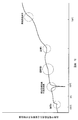
鋳造および熱間加工された原材料状態の形状記憶合金素材を焼き鈍し後、冷間ダイス引きや冷間圧延で所定寸法に加工する。この加工された形状記憶合金素材から、加工硬化したままの素材試験片Hと、JISで定められている900℃付近の温度で十分焼き鈍した正準化試験片Nとを作成する。両方の試験片H,Nとも連続的にゆっくりとした熱サイクルを与え、加熱−冷却中の比熱変化(DSC測定)や電気抵抗変化、寸法変化、硬さ変化、組織変化等を観測し、形状記憶合金素材の変態点および温度特異点等を測定する。図1は、変態点および温度特異点等の大まかな関係を模式的に示したものである。図中の数値は、おおよその目安であり、単に各変態点や温度特異点等の関係を示したものである。これらの温度は、素材の種類によってかなり異なる。図2,3は、実際のDSC(走査型熱量計)のデータ例である。
【0061】
本実施例では、この測定のため実施した熱サイクルの温度の範囲を、最高加熱温度が約800℃、最低冷却温度が液体窒素温度のマイナス196℃とした。加工硬化したままの試験片Hからは、主に温度特異点S、再結晶温度Rが観測される。ここで、温度特異点Sは後述する強度の塑性変形が緩和する温度域Dと再結晶温度Rとの間に見られる比熱や電気抵抗や硬さ等の変態を示す物性値の変曲点である。今のところ、本発明者は、この温度特異点は粒界の変態に関わるものであると推定している。一度、加熱再結晶をした試験片Nからは、形状記憶効果に関係したAs、Af、Ms、Mfの各変態点の他、試験片Hとの比熱の差として強度の塑性変形のみが緩和する温度域D、および温度特異点Bが観測できる。前記温度特異点Bは、サブゼロ温度域において見られる比熱や電気抵抗等の変態を示す物性値の変曲点であり、サブゼロ温度域の変態点と考えられるものである。試験片Hにおいてもこのような特異点が観測されることもあるが、試験片Nほど明確ではなく、内部応力のせいか、温度がずれる傾向があるため、温度域Dと再結晶温度R以外の変態点は、試験片Nのものを採用する。
【0062】
温度特異点Bは、材料の組成によっても異なるが、液体窒素等を使用しないと得にくい−40℃から−150℃に及ぶ極低温度域にあることが多く、普通の冶金学的測定環境では見つけにくい。また材料の状態によっては、明確に確認できないこともあり、これまで文献等でもほとんど見られない。しかしこの温度Bは、本実施例において特に重要な温度である。DSC(走査型熱量計)等で得られるMf点(マルテンサイト変態の終了温度)は、主に素材の体積の大半を占める結晶粒内部のそれを測定しているものと思われる。しかし結晶粒界は、このMf点温度でも方位の異なる結晶に挟まれて拘束された状態のため、オーステナイト相に近い状態のまま残留している成分があると考えられる(残留オーステナイト相)。さらに塑性変形による加工硬化や粒界特有の不純物析出等による弾性エネルギーの高い状態も考えられるため、拘束を受けた結晶粒界付近の組織のMf点だけが低い温度に移動しても不思議ではない。DSCによるMf点よりもかなり低い温度にある温度特異点Bは、このような粒界付近の組織のMf点的なものと本発明者は考えている。DSCのデータでは、各変態点および特異点とも比較的広い温度範囲を持ったなだらかな変曲点で明確なピークを持つことは少ない。これは測定している素材が結晶の大きさも方位も拘束状態もまちまちな多結晶体のためと考えられる。一般的に変態点といわれている温度もこの変態温度区間の中心や平均的な温度を指すものである。
【0063】
(工程1)
鋳造および熱間加工された原材料状態の形状記憶合金素材1を焼き鈍し後、該素材1に冷間加工で材料内部にまで強度の塑性変形が十分及ぶような強変形を引張方向に異方性を残しながら加え、線材状とする。具体的には、液体窒素を用いた極低温下で加工硬化度の限界に至るまで、図4のように、形状記憶合金素材1にダイス2による線引きを繰り返す( ただし、本発明においては、この作業は常温で行ってもよい )。ダイスの場合、全方向から外力が加わるため、強い変形で素材1の材料内にインゴット凝固時やそれ以後の熱間加工の際に生成された大きさも形も方位もランダムな結晶がほとんど破壊された状態になる。しかし、このような状態で加工しても引張方向には自由度があるため、収縮を起こすマルテンサイト的成分が残留する。本実施例においては、この成分は、引張方向に異方性があり、次に説明する工程2において再結晶時に結晶の成長方位を与える重要な要素となる。このような冷間加工後の形状記憶合金素材1の状態は、長手方向に異方性を残した状態で結晶がほとんど完全に砕かれたアモルファス的な状態と考えられる。
【0064】
前記冷間加工は、本発明においては、前述のように常温で行ってもよいが、本実施例のように液体窒素温度等のような温度特異点Bより十分低い、極低温下で行うことが好ましい。これは、材料内部に残留する僅かな非マルテンサイト組織もマルテンサイト化するためである。一般的にいうマルテンサイト変態終了点(Mf点)は、完全焼き鈍しをした試験片で測定した温度であり、現実の加工された材料には、この温度でも多くの非マルテンサイト組織が多く残留している。非マルテンサイト組織としては、残留オーステナイトや加工硬化により生じた組織等が考えられる。この処理は、残留オーステナイト的成分が、なるべく残らないような状態で加工することに要点がある。オーステナイト成分が残留すると、加工後の材料の状態によっては、部分的であれ、可逆的すべりを可能にしたり、異方性を持った再結晶過程を妨害し、以後の処理を不完全にする場合がある。これは最終的に形状回復率や伸び等で動作寿命に影響を与えることにもなる。ダイス2の加工熱による温度上昇にも注意する必要がある。特に共有結合性の強いTi−Ni系、Ti−Ni−Cu系形状記憶合金の場合、変形抵抗がひずみ速度に強く依存する傾向があり、発熱しやすい。強応力下で温度が上昇した状態では、マルテンサイトとオーステナイトが混在して存在するため、強度のあるオーステナイトより弱いマルテンサイトの方が優先的に破壊され、オーステナイトが残りやすくなる。完全に変態しきったオーステナイトは、方向性を持ちにくく、したがって引張方向に異方性を出しにくい。よって、高速な加工は注意が必要である。B点より十分低い、例えば液体窒素温度等で強加工すると、この処理の理想に近い状態が得られるものと考えられる。このような温度下では、形状記憶合金素材1中のオーステナイトのほとんど全てがマルテンサイト化するため引張方向に適した方位のマルテンサイトを除いて、他は全て均一に破壊される。残ったマルテンサイトが発生する応力が、次に説明する工程2の再結晶の異方性を司る因子となる。
【0065】
なお、強加工の方法としては、線引き加工の他に、冷間圧延加工やショットブラストも有効な方法である。また、スパッタリングやメッキ等で素材1を作った場合は、はじめからアモルファス的組織状態と考えられるので、この工程1のように冷間強加工により結晶構造を破壊する必要はなくなる。
【0066】
(工程2)
工程1を経た形状記憶合金素材1の両端部を、図5のように、たるまないように適当な張力を作用させたまま拘束手段3で拘束して固定することにより、引張方向の応力を加えた状態でひずみを拘束し、再結晶開始点以上でかつ該再結晶開始点付近の温度に数秒ないし数分の短時間加熱する。これにより、引張方向に異方性を持った実質的に大きさが均一で等軸の微細結晶粒が生成する。これは、引張方向の異方性のため加熱に伴って強い内部引張応力が発生するが、再結晶がこの内部応力を徐々に緩和する方向に優先的に進むためと考えられる。このような材料の状態にすると、最終的な寸法安定性や運動特性が良くなる。拘束、加熱する前に加える応力の大きさは、比較的制約が少なく広い範囲で同様の効果が期待できる。工程1のように冷間で強加工を加えた形状記憶合金素材1は、加熱中に形状を回復できる変形成分をある程度残留する。したがって本工程において応力を加えず、無負荷でたるまないように、ただ長さを拘束するだけでも、加熱中に形状記憶合金が収縮しようとして応力が発生するため、前記のように応力を負荷してひずみを拘束するのとほぼ同様な効果を持たせることができるので、そのようにしてもよい。反対に強い応力を負荷した状態で拘束を行っても、必要以上の応力は、再結晶中に緩和されるため影響が出にくいが、仕上がり寸法の精度が落ちる。例えば線材を引張りで処理する場合なら細くなってしまう。基本的には、回復再結晶が開始する段階で引張方向に適当な負荷応力状態であればよい。大切なのは、再結晶時になるべく引張方向以外の応力や拘束が加わらないようにすることである。実際には、本実施例では、10〜100Mpa程度の応力を加えて拘束した。
【0067】
なお、トンネル炉を使った量産化を考えた場合、上述のように拘束する代わりに外力によって応力を加えたままの状態で同様な加熱処理を行っても似たような処理ができるが、応力を負荷したままの状態だと、せっかくできた方向のそろった持った微細結晶が、一部壊れてしまうためか、拘束状態ほど性能のいい製品ができない。また応力の管理も難しい。
【0068】
応力をかけ拘束する効果は、以下のように考えられる。工程1を経た状態の材料では、材料内部の再結晶による結晶粒の生成が、より変形を強く受け、より格子構造が乱れた応力場が強い部分から優先的に起こると考えられる。引張方向の外力によって応力を加えた状態でこの結晶生成を行うと、その応力との釣り合いの中で結晶粒内部および結晶粒界がともに残留応力やひずみが消去された状態となる。このようにしてできた材料は、冷却後、外力を取り除くかまたは拘束を解いて、応力を取り去ると、緩和された内部応力のバランスが崩れ、構造的に引張方向に偏った残留応力場を持つような素材1となる。また一般的に結晶ができるとき、生成された結晶内部より結晶の外の部分の方が不純物濃度がはるかに高く、最終的には結晶粒界に集まるものと考えられる(組成的過冷現象)。この不純物としては、炭素、カーバイド、酸化物等の素材1の大半の部分と異なる組成の物質が考えられる。この工程2により、前記不純物も応力を加えた状態で安定な位置に落ち着き、冷却後、応力を取り去った状態では、構造的に引張方向に偏った状態になる。これらの再結晶の異方性と不純物による引張方向の偏りは、永久変形を防ぐ弾性的なエネルギー障壁および双方向性形状記憶効果を起こす応力場のもとになると考えられる。またその異方性のため次の工程3以降を行いやすくする。事実、炭素濃度の違いにより双方向性形状記憶効果の出現しやすさが異なる。
【0069】
この工程2では、共有結合性の強い材料の方が熱伝導が悪いためか微細結晶を作りやすい。現状では、Ti−Ni系よりもTi−Ni−Cu系の方が微細結晶を作りやすいようである。あくまで比較の問題であるが、加熱温度が高すぎたり、加熱時間が長すぎると、粒界付近の組織がなくなったり、結晶が大きくなりすぎるためか、できた材料のアクチュエータとしての性能が劣り、材料的にも不安定である。一般的には、材料中の結晶粒が大きな方が形状回復ひずみ、すなわち回復力が大きくなる傾向がある。しかし本処理方法では、金属材料としては小さめの数ミクロン以下のできるだけ実質的に大きさが均一で等軸の微細な結晶粒にする方が良い結果が得られる。これは、以後の結晶粒の方位を揃える過程が重要と考えられるからである。結晶粒が小さく実質的に大きさが均一の方が結晶粒を回転させやすいのである。また形状記憶効果による繰り返し運動に適した安定な結晶粒の大きさが存在するものと考えられ、この大きさは、比較的小さいようである。本処理に最適な結晶粒の大きさは、素材1や処理対象の形や大きさにも関係する。
【0070】
(工程3)
工程2を経た材料に再び、温度特異点Bを十分下回るような極低温下の完全なマルテンサイト状態において、図6のように、断面方向に無拘束の自由引張状態で、反力が急激に増加するところまで、強い引張り力F1を加え、引張方向に変形を与える。温度特異点Bは、強応力、強変形によって変化することもあるので、前記極低温状態を得るには、ドライアイスや液体窒素等を使う。この状態で結晶粒内部、結晶粒界ともに完全なマルテンサイト状態になっているものと考えられる。結晶粒内部にも粒界にもオーステナイト相を残留させないような状態で変形を与えることがポイントである。特に結晶粒内部は、先述の原子が可逆的なすべりを生ずる範囲では、非常に柔らかく外力にしたがって容易に変形して反発しない。この結晶粒内部の巨大な変形ひずみは、一般的な金属の弾性ひずみの数十〜100倍に達する。他方、方位の違う結晶粒に挾まれ拘束された結晶粒界付近の組織は、結晶粒内部の組織のように自由に移動ができないため、周りの結晶粒の変形とともに結晶粒同士が、外力にしたがってずれる方向に集中的に変形されることになる。結晶粒界付近の組織にとってこの巨大なすべり変形は、先の可逆的すべりの範囲を超えた塑性変形である。材料全体では、外力が緩和され、そのひずみが結晶粒界付近の組織に蓄積される形で変形が起こる。この過程では力をかけすぎて塑性変形が結晶粒内部まで及ばないようにしなければならない。しかしこの限界の力は、図7の例のように連続的に変形時の応力−ひずみ線を観測することで容易に知ることができる。本実施例のように形状記憶合金素材1が線材である場合、極低温下で、引張方向以外の外力を受けない自由引張り変形を行って行くと、比較的小さな力で変形が起こった後に、急激な反力の増加として前記限界が観測できる。反力を無視し無理に変形を行うと、結晶粒内部にも塑性変形が及び、内部に欠陥を生じたり、材料が突然破断する虞もある。一般には、300〜500Mpa位の応力を与えることが好ましい。
【0071】
なお、引張方向によりよい性能を得るには、この実施例のように特定の方位以外の拘束がない自由引張り等の変形が望ましい。比較的小さな断面の材料をこのような状態で変形させると断面内の拘束が緩いため、結晶粒同士の回転やすべりがおきやすい。反対にダイス線引きのような内部の結晶の動きまでも拘束するような強度の変形は、この過程の効果を損なう。
【0072】
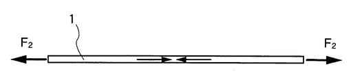
(工程4)
工程3を終了した形状記憶合金素材1を図8のように工程3より弱い引張り力F2を断面方向に無拘束の自由引張状態で作用させた状態で、温度特異点S付近まで析出や拡散等が生じない速度(例えば、100〜200℃/min程度の速度)で加熱後冷却する。力F2は、引張方向に連続的な変形が起こらない範囲の小さな力である。この過程でも強制的にひずみを加えるのではなく、応力を管理するといった方がいい。一般的には、100〜200Mpa位の応力が好ましいと考えられる。あらかじめ引張方向の変形を与えた状態で拘束し、温度Sまで加熱しても形状回復力が発生するため同様な効果が得られるが、拘束時のひずみの管理が難しい。この状態では、結晶粒内部が完全に硬いオーステナイト相になるため、結晶粒界付近の組織は拘束された状態になる。温度Sでは、無理な変形もなく、原子配列が比較的整った結晶粒内部の組織は安定しており、変化することは少ないが、工程3で強い塑性変形による強度の結晶的な乱れを含んだ結晶粒界付近の組織は、結晶粒内部より弾性エネルギーあるいは結晶を元に戻そうとする力学的なエネルギーが高い状態にあるものと考えられる。したがってこの部分は、より少ない熱エネルギーで再結晶的な変化を起こして、より安定な状態にもどろうとする。このように工程4の過程では、結晶粒界付近の組織だけが、選択的に不可逆なすべり変形を起こし、結果として隣り合う結晶粒同士が外部からの引張方向の力を緩和するように相対的にずれることになる。これをもう少し大きな視点から見ると、結晶粒が形状記憶効果によって可逆的な変形を行う際にその方位が揃って、よりスムーズに運動ができるように回転することになる。すなわち予定運動方向(引張方向)の運動に障害が少ない方向に全ての結晶が並ぶことになる。形状記憶合金の結晶には兄弟晶といわれる簡単に可逆的なすべり変形を起こす結晶面が立体的に多数存在する(例えばTi−Ni系合金の場合、この兄弟晶といわれる変形が可能な方位が立体的に24もある)ため、比較的僅かな回転で、この引張方向の変形の都合のいい方向に落ちつくことができる。各結晶粒は、いったんこの安定な位置に落ちつくと、材料全体が引張方向の変形を受けても、最大限自身の可逆的な変形を行えるため、結晶粒をさらに回転させる力は発生しにくい。すなわち材料的に安定になる。工程2がうまく行かず、各結晶粒のサイズが異なると整合性の悪い結晶の内部には、無理な応力や変形が発生し、材料的には不安定になる。当然、この工程4での荷重や温度や加熱時間が適切でなかった場合は、結晶粒が回転しないばかりか、結晶粒内部まで変化がおよび、性能が悪くなる。
【0073】
なお、微細な多結晶材料を使った工程3および4で起こる現象は、微細結晶粒超塑性 (Super Plasticity) に近い現象と思われる。従来知られている微細結晶粒超塑性と本発明における現象との大きな違いは、本発明においては連続的な変形が持続するような状態になる前に処理を終了する点である。ただし、温度Sより加熱温度を高め、保持時間を長くしてゆっくり変形させると、大きな永久ひずみを発生することがある。
【0074】
(工程5)
工程4を経た材料に再び工程3を行う。なお、通常は、工程3−工程4の過程を1回行えば、結晶の大半が運動方向に都合の良い向きに並ぶものと思われ、それ以降の繰り返しでは、対数的に効果が少なくなって行く傾向がある。しかし素材によっては、工程3および工程4の結果に差があり、この処理の繰り返し回数は、微妙にでき上がりの性能に影響する。そのため工程3および工程4を交互に繰り返すことで徐々に性能が向上することもある。これは、不純物や材料の成分、履歴によって結晶を作る金属間化合物に、兄弟晶を作りやすい方位が少ないものができることもあるためと考えられる。実際には、処理の繰り返し回数を全ての処理過程を一応終えた材料の運動試験の結果で決めることができる。一つの判断基準は、極低温の変形時の応力が、最初の工程3のときよりも充分小さいかまたはゼロになることを確認することである。ただし、本発明においては、必要がない場合はこの工程5を行わなくてもよい。
【0075】
(工程6)
最高加熱温度を温度D付近、最低冷却温度を工程3と同様な温度とする(なお、本発明においては、前記最低冷却温度はM f 点以下とすればよいが、できれば本実施例のように工程3の温度と同様な温度とするとよい )。アクチュエータとして使用される場合に想定されるより強く、材料を劣化させない位の力をかけた状態で最高加熱温度と最低冷却温度の間を繰り返し加熱冷却する。場合によるが、一般的には100〜300Mpa位の応力が好ましいと考えられる。この場合、加熱−冷却による材料の動きを拘束してはならない。加熱時に比べ、冷却時に加わる力を大きめにする(本発明においては、必ずしもそうしなくてもよいが、このように冷却時に加わる力を大きめにするとより効果的である)。この処理は、粒界付近の組織を適度に加工硬化させ、材料の寸法安定性を確保するとともに引張方向の変形と同じ方向すなわち、形状記憶効果による形状回復と反対の方向に弾性エネルギー場を与える作用がある。一般的なトレーニングと同じ効果をねらった処理である。この工程の完了により、全ての処理工程が完了する。
【0076】
図9の曲線Iは、本実施例により得られたTi−Ni−Cu系形状記憶合金の温度−ひずみ特性の一例を示している。なお、この図には、比較のために、従来のアクチュエータ用形状記憶合金の特性(曲線II,III)も一緒に示してある。図10は、図9の特性を求めるための試験条件を示しており、温度変化率1℃/minとした恒温槽内において、それぞれ線材状の形状記憶合金1’に100Mpaの荷重負荷を作用し、温度と収縮変位(ひずみ)εとの関係を測定した。図9の曲線Iに示されるように、本実施例により得られた形状記憶合金は比較的広い応力範囲で温度のヒステリシスをほぼ0にすることができた。曲線IIで示される従来の形状記憶合金は比較的に高温で動作する高温タイプのもの、曲線IIIで示される従来の形状記憶合金は中温処理されたものであり、いずれも大きなヒステリシス特性を示している。
【0077】
図11〜16は、本発明による形状記憶合金の処理方法の第二実施例を示す。本実施例は、完成後の形状記憶合金がコイルばね状をなし、アクチュエータとして使用される際、加熱すると記憶しているコイル長さに収縮する一方、冷却すると弛緩して低温時の元のコイル長さに伸張する(すなわち、引きばね型として機能する)か、または反対に、加熱すると元の記憶しているコイル長さに伸張する一方、冷却すると弛緩して低温時の元のコイル長さに収縮する(すなわち、押しばね型として機能する)ことが想定される場合である。本実施例における予定運動方向はねじり方向である。
【0078】
(準備作業)
前記第一実施例の準備作業と同様の作業を行う。
【0079】
(工程1)
前記第一実施例の工程1と同様の作業を行い、所定の太さの線材を作る。これにより、形状記憶合金素材1に引張方向に異方性が残るが、本実施例ではこの引張方向の異方性は最終的な結果に実質的な影響を与えない。
【0080】
(工程2)
工程1を経た線材状の形状記憶合金素材1を図11のように、予定運動方向に十分ねじってねじり変形を追加し、これを図12のように拘束手段3で拘束した状態とする。このねじり変形の追加は、前記実施例の場合と同様の理由により、常温で行ってもよいが、B点より十分低い、極低温下で行うことが好ましい。続いて、前記拘束状態で、再結晶開始点以上でかつ該再結晶開始点付近の温度に短時間加熱する。すると、ねじり方向の異方性のため、加熱に伴い強い内部せん断応力が発生するが、再結晶がこれを緩和する方向に優先的に起こり、ねじり方向に異方性を持つ、実質的に均一な微細結晶粒が生成する。
【0081】
(工程3)
図13のように、工程2を経た形状記憶合金素材1に低温または極低温下の完全なマルテンサイト状態で、反力が急激に増加するところまで、強いねじり力で工程2と同じ方向にねじり変形をさらに加える。この場合、第一実施例の場合と同様に結晶粒内部に塑性変形が及ばないように、ねじりトルクが管理される必要がある。またねじり方向以外、なるべく変形が拘束されないようにする。
【0082】
(工程4)
図14のように、工程3を経た材料をねじり変形が戻らないようにして心材4に巻き付けて行く。ねじりながら心材4に巻き付けてもよい。5は形状記憶合金素材1の端部を丸棒状の心材4に固定した箇所を示している。巻き付ける向きによって押しばね型(加熱時にコイル長が長くなるばね)と引きばね型(加熱時にコイル長が短くなるばね)の違いが出る。図14は引きばね型とする場合を示しており、押しばね型とする場合は逆向きにねじりながら心材4に巻き付ける。引きばね型の場合、強度にねじりながら巻くことで、強制的に心材4に巻き付けるというより、自分自身でばね状の形態を形成させる効果もある。
【0083】
(工程5)
次に、図15のようにねじりながら巻き付けた状態で拘束したまま温度Sまで析出や拡散等が生じない速度(例えば、100〜200℃/min程度の速度)で加熱後冷却する。これにより、前記第一実施例の場合と同様にして、結晶が予定運動方向、すなわちねじり方向に都合の良い向きに並ぶ。前記工程4では、ねじり以外に曲げ変形も入るため、引張りのときよりも強い変形が加わる可能性があり、加工硬化を起こす部分も出てくることがあるので、加熱温度を少し高めに設定し、短時間に余分な加工硬化の除去を行った方がよいこともある。
【0084】
(工程6)
心材4を抜き、極低温下で、引きばね型の場合は図16のように引き延ばし、押しばね型の場合は、圧縮方向に変形させる。コイルばね状の形状記憶合金素材1内に応力が残留しているためか、心材4に巻いたまま、再び極低温にするだけでもある程度の効果がある。このようにしてできたコイルばね状の形状記憶合金素材1を適当に伸ばした後、再びさらにねじりながらコイルばね状に巻き、工程3,4,5,6を数回繰り返すと性能はさらに向上することもある。
【0085】
(工程7)
工程6により得られたコイルばね状の形状記憶合金素材1に、必要に応じて変形を拘束しない状態で運動方向の力を加えたたまま、低温あるいは極低温と温度Dの間で熱サイクルを数回以上かける。この工程は、前記第一実施例における工程6に相当する慣らし運転ないしはトレーニングの過程である。この工程の完了により、全ての処理工程が完了する。
【0086】
なお、本発明は、前記各実施例以外の形状および運動を行う形状記憶合金にも適用できるものである。変形様式が異なるだけで基本的な処理工程は同様と考えられる。
【0087】
【発明の効果】
以上のように本発明による形状記憶合金の処理方法および形状記憶合金は、
(イ)応答性のよい形状記憶合金を得ることができる、
(ロ)使用可能な温度域が広い形状記憶合金を得ることができる、
(ハ)実用的に有効に取り出せる力が大きい形状記憶合金を得ることができる、
(ニ)繰り返し大きな運動ひずみが取り出せる形状記憶合金を得ることができる、
(ホ)巨大な双方向性形状記憶効果を持つ形状記憶合金を得ることができる、
(ヘ)破断に至るまでの寿命が長い形状記憶合金を得ることができる、
(ト)記憶形状が消失しにくい形状記憶合金を得ることができる、
(チ)運動ひずみの減少が少ない形状記憶合金を得ることができる、
(リ)前記の種々の優れた特性が長期多数回にわたる繰り返しにおいても安定している形状記憶合金を得ることができる、
(ヌ)これまで脆性が強く、割れやすいため利用が困難とされていた材料をも素材として用い、靱性を持った線材や板材状の形状記憶合金とすることができる、
(ル)形状記憶合金の組織を壊すことなく、結晶の方向を揃えることができる、
等の優れた効果を得られるものである。
【図面の簡単な説明】
【図1】 本発明の形状記憶合金の処理方法の第一実施例における形状記憶合金素材の変態点および温度特異点等を示す模式図である。
【図2】 加熱時に現れるTi−Ni−Cu系形状記憶合金の変態点および温度特異点等の実例を示すDSC測定図である。
【図3】 Ti−Ni−Cu系形状記憶合金の極低温の温度特異点Bの実例を示すDSC測定図である。
【図4】 前記第一実施例の工程1を示す断面図である。
【図5】 前記第一実施例の工程2を示す断面図である。
【図6】 前記第一実施例の工程3を示す断面図である。
【図7】 前記第一実施例の工程3における変形時の応力−ひずみ線図の例である。
【図8】 前記第一実施例の工程4を示す断面図である。
【図9】 前記第一実施例により得られた形状記憶合金および従来の形状記憶合金の温度−ひずみ特性の比較を示す特性図である。
【図10】 図9の特性を求めるための試験条件を示す説明図である。
【図11】 本発明の形状記憶合金の処理方法の第二実施例の工程2において形状記憶合金素材をねじり変形する状態を示す斜視図である。
【図12】 前記第二実施例の工程2においてねじり変形した形状記憶合金素材を拘束して加熱する状態を示す断面図である。
【図13】 前記第二実施例の工程3を示す斜視図である。
【図14】 前記第二実施例の工程4を示す斜視図である。
【図15】 前記第二実施例の工程5を示す斜視図である。
【図16】 前記第二実施例の工程6を示す斜視図である。
【符号の説明】
1 形状記憶合金素材
2 ダイス
3 拘束手段[0001]
BACKGROUND OF THE INVENTION
The present invention relates to a shape memory alloy suitable for use as an actuator (driving device) and a method for processing the shape memory alloy to obtain the shape memory alloy.
[0002]
[Prior art]
Conventionally, in general, when processing a shape memory alloy material so as to have characteristics suitable for use, the crystal grains have not been refined or the orientation of the crystal grains has not been adjusted.
[0003]
On the other hand, in order to use a shape memory alloy, it is necessary to memorize a predetermined shape, and for this purpose, it is necessary to perform a heat treatment specific to each alloy. Conventionally, this heat treatment is called a “shape memory process”, but it is a very delicate process, and it is necessary to strictly manage the conditions. For example, as a general shape memory processing method for Ti-Ni alloys, which has been performed more often than before, the shape memory alloy is sufficiently worked and hardened in advance, then processed into a predetermined shape, and the shape is left as it is. A method of fixing and placing at a temperature of 400 to 500 ° C. for several minutes to several hours (referred to as intermediate temperature treatment), or after placing it at a temperature of 800 ° C. or higher for a while and then rapidly cooling and processing into a predetermined shape There was a method of keeping this at a relatively low temperature of 200 to 300 ° C. (referred to as low temperature treatment), etc. (reference: published by Industrial Research Committee, Shoji Ishikawa, Sadao Kinashi, edited by Miwa Manabu, “ A collection of shape memory alloy applied ideas seen in the latest illustrated patents ”).
[0004]
[Problems to be solved by the invention]
When a conventional general shape memory alloy is used as an actuator, there are mainly the following drawbacks.
[0005]
(A) poor responsiveness (speed),
(B) Ms, MfSince it is difficult to raise the point, the usable temperature range is limited.
(C) The force that can be effectively removed is small,
(D) short life to break,
(E) Loss of memory shape or permanent distortion is likely to occur in a short period of time.
(F) Strain that can be taken out as motion within a short period (hereinafter referred to as motion strain) decreases.
(G) In the case of a difficult-to-work shape memory alloy material having strong covalent bonding as an intermetallic compound, such as Ti—Ni, Ti—Ni—Cu, etc., depending on the composition, the brittleness becomes particularly strong and easily cracked. Difficult to use,
Because of such problems, conventionally, 80% or 90% or more of the applications of the shape memory alloy have been used as superelastic spring materials, and the remaining few have been used as actuators. Moreover, most of the shape memory alloys used for actuators are in the shape of coil springs, wire rods or plate materials, and utilize bending deformation or torsion and shape recovery from bending deformation (in the case of coil spring shapes, macroscopic The shape memory alloy expands and contracts, but in the true sense, its deformation is torsional and bending deformation). The reason for using bending deformation or torsion and shape recovery from bending deformation is that the conventional general shape memory alloys have a very small range of shape memory effects that can be stably used, and this small strain This is because it must be used in such a form that is amplified. It is said that the kinetic strain of a conventional general shape memory alloy is a maximum of several to 10% in terms of tensile strain, but this is a story of one to several operations. When recovery was repeated, the kinematic strain also decreased, the memory shape was lost, and eventually it broke.
[0006]
Also beforeObedienceThe conventional shape memory treatment methods for general Ti-Ni alloys are all produced by generating a structure that can partially generate a shape memory effect and superelasticity in a structure strengthened by work hardening. It is intended to maintain the shape stability and at the same time obtain superelasticity and shape memory effect. In other words, in order to obtain the stability of the shape, it is a process that cannot be finished without sacrificing the superelasticity and the shape memory effect to some extent.
[0007]
On the other hand, the present inventor previously disclosed in JP-A-63-240939 a thermal cycle having a heating process including a transformation temperature section and a cooling process in a polycrystal, and at least a part of this thermal cycle. In addition, a crystal orientation rearrangement method for a polycrystal was proposed, in which an energy field having directionality is applied to the polycrystal. When this polycrystal crystal orientation rearrangement method is applied to a shape memory alloy, the drawbacks of the conventional general shape memory alloy can be drastically improved.
[0008]
However, in this crystal orientation rearrangement method, when applied to a shape memory alloy, the crystal grains are not refined, but rather the crystals are grown and enlarged. In addition, there is a surface that destroys the structure of the shape memory alloy finally obtained by applying a tensile force or the like in the final process of aligning the crystal directions of the shape memory alloy material. For this reason, there has been a somewhat insufficient aspect in solving the problems of the conventional general shape memory alloys.
[0009]
The present invention has been made in view of such conventional circumstances, and one object of the present invention is to provide a shape memory alloy having good responsiveness and a method for processing the shape memory alloy to obtain the shape memory alloy. There is to do.
[0010]
Still another object of the present invention is to provide a shape memory alloy having a wide usable temperature range and a processing method of the shape memory alloy for obtaining the shape memory alloy.
[0011]
Still another object of the present invention is to provide a shape memory alloy having a large force that can be effectively and effectively taken out, and a processing method of the shape memory alloy for obtaining the shape memory alloy.
[0012]
Still another object of the present invention is to provide a shape memory alloy capable of taking out a large kinematic strain repeatedly and a method of processing the shape memory alloy for obtaining the shape memory alloy.
[0013]
Still another object of the present invention is to provide a shape memory alloy having a huge bidirectional shape memory effect and a processing method of the shape memory alloy for obtaining the shape memory alloy.
[0014]
Still another object of the present invention is to provide a shape memory alloy having a long life until failure and a method for treating the shape memory alloy to obtain the shape memory alloy.
[0015]
Still another object of the present invention is to provide a shape memory alloy in which the memory shape is not easily lost and a method of processing the shape memory alloy to obtain the shape memory alloy.
[0016]
Still another object of the present invention is to provide a shape memory alloy with little reduction in kinematic strain and a method of processing the shape memory alloy to obtain the shape memory alloy.
[0017]
Still another object of the present invention is to provide a shape memory alloy in which the above-mentioned various excellent characteristics are stable even after repeated over a long period of time, and a method for processing the shape memory alloy to obtain the shape memory alloy. It is in.
[0018]
Still another object of the present invention is to use a material that has been considered to be difficult to use because of its strong brittleness and easily break, and a shape that can be used as a shape memory alloy in the form of a tough wire or plate. The object is to provide a method for treating a memory alloy.
[0019]
Still another object of the present invention is to provide a method of processing a shape memory alloy that can align the direction of crystals without destroying the structure of the shape memory alloy.
[0020]
Still other objects of the present invention will become apparent from the following description.
[0021]
[Means for Solving the Problems]
Shape memory alloy crystal grains have an orientation, and microscopically, there is a limited number of directions in which reversible slip or shear deformation (brother crystals) with limited movement range of atoms can occur, but there are multiple . For example, in the case of a Ti-Ni alloy, there are 24 three-dimensional orientations that can be deformed, referred to as brother crystals. In the present invention, the direction of the crystal of the shape memory alloy is substantially aligned with the direction suitable for the planned movement direction, in other words, the direction suitable for the movement of the shape memory alloy. Here, in the present specification, the planned movement direction refers to a direction assumed when the processed shape memory alloy is used as an actuator, such as tension or torsional bending movement. For example, when a linear object is used in a contracting-relaxing form, it is in the tension direction, and when it is used in a coil spring shape, it is in the torsion direction. Strictly speaking, the planned direction of motion can be said to be the direction of twisting and bending, but in reality the ratio of torsional elements is much higher, so the planned direction of motion is substantially Torsional direction).
[0022]
One of the processing methods of the shape memory alloy according to the present invention is a process in which the shape memory alloy material is made into a fine crystal structure having a substantially uniform crystal size, and the direction of the crystal is substantially suitable for the predetermined motion direction. And aligning the direction.
[0023]
One of the shape memory alloys according to the present invention is a polycrystal of a fine crystal, the size of the crystal is made substantially uniform, and the direction of the crystal is substantially in a direction suitable for movement in a predetermined direction. Are aligned.
Note that the size of each crystal grain is preferably 10 microns or less, particularly preferably several microns or 1 micron or less. With such a size, even if deformation-shape recovery is repeated, a particularly stable state is obtained.
[0024]
In general, the unique properties of each material in a crystalline material are often based on phenomena in the crystal of the material. Thus, of course, these unique properties are often most noticeable when the material is in a single crystal state. For this reason, in order to utilize a certain excellent property or function of a material, generally, the best result is obtained when the material is a single crystal. This is also basically the case for shape memory alloys. Single-crystal shape memory alloys can be deformed with a very small force in the slip direction in a range where reversible slip can occur in a low temperature state where the whole becomes a complete martensite state. A good shape memory effect can be obtained (the reversible slip deformation here is a shear deformation that allows reversible motion within a limited range that is the basis of the recoverable deformation by the shape memory effect. It is not a permanent and continuous slip of atoms that causes plastic deformation).
[0025]
However, in practice, it is extremely difficult to industrially produce a single crystal material, and even if it can be produced, it is very expensive. In the case of a shape memory alloy, the structure becomes unstable when a single crystal is used.
[0026]
The conventional general shape memory alloy is, of course, polycrystalline, and the orientation of each crystal is generally random and the size of each crystal is non-uniform. (This will be explained in more detail later).
[0027]
However, the present inventor made a polycrystal of a fine crystal like the shape memory alloy of the present invention, and made the crystal size substantially uniform and convenient for movement of the crystal in a predetermined direction. It has been found that a shape memory alloy having both the advantages of a single crystal shape memory alloy and the advantages of the conventional general shape memory alloy can be obtained if they are aligned substantially uniformly in a good direction. If the size and direction of movement of the crystal grains inside the shape memory alloy are aligned, there will be no excessive deformation even if a huge shape recovery force is generated in each crystal grain, and the internal structure will be difficult to break. . Moreover, if each crystal is appropriately small, structural contradiction caused by a difference in deformation direction and the like is small, and the crystal itself is not easily broken. Furthermore, such materials have a high capacity to absorb structural contradiction because the volume ratio of the structure near the crystal grain boundary is large. Further, in such a material, even if a material is brittle at the stage of the material, the structure in the vicinity of the crystal grain boundary shows an amorphous property, so that it can be made into a wire or plate material having high toughness in a wide strain range. Even if it is fine, if the direction of each crystal is aligned, a relatively large shape memory effect can be stably extracted. In addition, since the direction in which each crystal easily moves is aligned, the force required for deformation may be small. Since the volume ratio of the structure near the crystal grain boundary is large, large elastic energy can be stored in this part without using a method such as precipitation of impurities. In combination with this, a stable and large bidirectional shape memory effect can be obtained.
[0028]
Although this partly overlaps with the matters just described, the shape memory alloy of the present invention has excellent characteristics as listed below.
[0029]
(A) Since the temperature hysteresis is small on the temperature-strain line and the transformation temperature range is also narrow, heating-cooling is performed quickly, responsiveness is good, and high-speed reciprocating motion is possible. For example, when the present invention is applied to a Ti—Ni—Cu-based shape memory alloy, the temperature hysteresis can be almost zero in a relatively wide stress range. In addition, the shape memory alloy of the present invention succeeded in repeatedly taking out a continuous reciprocating strain of nearly 80% of the full stroke (strain ε = 4%) under a working load of 150 Mpa at a temperature range of only 10 ° C. ing. When compared to an engine, this is the same size as the conventional shape memory alloy, with a higher rotational speed. Combined with the improvement in load bearing capacity, it has the same meaning as increasing the horsepower by several steps. A mechanism that requires bi-directional motion, such as a servo actuator, can be expected to significantly improve responsiveness.
[0030]
(B) The force that can be practically extracted from the shape memory alloy (hereinafter referred to as recovery force) can be increased. The recovery force is determined not by the maximum recovery stress but by the limit of stress considering fatigue that can be used repeatedly. This is the maximum torque for an engine or motor. The shape memory alloy subjected to this treatment has a high limit of the stress that can be practically used in this repeated operation even if the material has the same maximum recovery stress. Conventional shape memory alloys have a small recovery force, and when the movement is repeated with excessively large stress applied, the memory shape is lost (so-called sagging), the movement strain is reduced, and the fracture occurs as described above. This means that the actuator motion life is shortened. As described above, the conventional general shape memory alloy actuator is often in the shape of a coil spring because of this circumstance. Even if the shape memory alloy in the shape of a coil spring is deformed. The strain of the material itself is very small. Therefore, the actual stress used is considerably smaller than the force that can actually be generated.
[0031]
(C) A large strain can be extracted repeatedly. In the case of a linear shape, it is possible to repeat deformation and shape recovery by 5% or more in tensile strain. A value of 5% or more in terms of kinematic strain corresponds to the fact that a 1 m long round bar expands and contracts by 5 cm. This is a much larger amount of deformation than a general coil spring is deformed-recovered between a coil shape and a linear shape. This value is much larger than the available range of common shape memory alloys, including superelastic alloys. When the treatment of the present invention is applied to a highly brittle material such as a Ti—Ni—Cu alloy, this huge kinematic strain may be stably taken out over 100 million times. When a conventional shape memory alloy is used in a coil spring, the kinematic strain is often 0.1% or less in terms of the tensile direction. Shape memory alloy coil springs are often used only with the same displacement as non-shape memory alloy springs such as iron.
[0032]
(D) It is possible to have a huge bidirectional shape memory effect. The bidirectional shape memory effect is a phenomenon in which a force is unnecessary or very little when deformation in the opposite direction to shape recovery is applied at a low temperature. In appearance, it behaves as if it remembered two shapes: a shape deformed at low temperatures and a shape recovered at high temperatures. For example, if you have a memory shape in the direction of the straight tension, when you heat it, it will shrink to the memorized length and become hard, but when it cools, it will soften so that your muscles will relax even under no load, It stretches to return to its original length and shape at low temperatures. In other words, it expands and contracts only by heating and cooling without applying a bias force from the outside. According to the literature and the like, the bidirectional shape memory effect is generally a partial phenomenon of ε = 1% or less in terms of tensile strain, and it is difficult to put it to practical use because it is unstable. In fact, there are few devices that use this phenomenon so far. On the other hand, when the processing of the present invention is used, a huge bidirectional shape memory effect can be generated in almost the entire region where the shape memory effect occurs, that is, in the range of the total strain amount that can recover the shape. In many cases using the treatment of the present invention, a bidirectional shape memory effect with a tensile strain of 5% or more can be exhibited even in a non-negative state. The polycrystalline shape memory alloy made by the process of the present invention is in a state in which the direction, size and arrangement of each crystal are adapted to deformation from the outside, so that it is opposite to the shape recovery direction inside the material applied during processing. The present inventor believes that a stable bidirectional shape memory effect having a magnitude close to the range of the total kinematic strain can be induced with a slight residual stress field. This enormous bidirectional shape memory effect is stably exhibited even in repeated operations close to 100 million times in a no-load state.
[0033]
(E) Long life to break. Conventionally, the operating life of shape memory alloy actuators is often about 100,000 times at most even when used with a small kinematic strain. In particular, when performing a large movement exceeding 2% by tensile strain, the life tends to be extremely short. However, in the shape memory alloy subjected to the treatment of the present invention, stable motion of 100 million times can be obtained within a huge motion strain range of nearly 5%.
[0034]
(F) The memory shape and the dynamic strain range are stable. That is, even if deformation-shape recovery is repeated, there is no or very little phenomenon in which the memorized shape is lost or the kinetic strain range gradually decreases. In other words, the influence of the magnitude of motion strain on the operating life is small. This material is thought to be because the size, direction and arrangement of each crystal grain are adapted to deformation from the outside. Deformation from the outside in a certain range is mainly handled by crystals that undergo massive reversible thermoelastic deformation unique to shape memory alloys, and strong external forces exceeding this range are in the grain boundary region where reversible thermoelastic deformation is unlikely to occur. The organization is considered responsible. Even with a large number of repetitive operations, each crystal grain is difficult to move, deform, rotate, etc., and the crystal itself is less susceptible to plastic deformation.
[0035]
(G) Even if the material is brittle, a tough wire or plate can be produced. The apparent toughness is higher than that of a material that has been subjected to general shape memory treatment, probably because it consists of fine grains that can be reversibly deformed and a structure near the amorphous grain boundary that has a large volume ratio. .
[0036]
(H) The excellent characteristics of each of the above items are stable even when repeated over a long period of time.
[0037]
One aspect of the processing method of the shape memory alloy according to the present invention is to at least recover the shape memory alloy material after applying a cold work to the shape memory alloy material to destroy the crystal structure inside the shape memory alloy material. In a state where stress is applied in the planned movement direction at the stage where recrystallization starts, the internal stress in the planned movement direction is generated by heating for a short time to a temperature above the recrystallization start temperature and near the recrystallization start temperature. Generating fine and substantially uniform crystal grains having anisotropy in the planned movement direction in a gradually relaxing manner;
Under extremely low temperatures at which no austenite phase remains, the shape memory alloy material is strongly deformed by the stress in the planned motion direction, and the crystal grains that are completely martensified in the direction along the stress are slip-deformed in a reversible range. A process of
Austenite transformation end temperature A in a state where an appropriate working stress is applied and restrained or the stress is still applied.fHeating the shape memory alloy material to a temperature between the point and the recrystallization temperature, and aligning the reversible sliding motion direction of each crystal grain in a direction suitable for the planned motion direction.
[0038]
The shape memory alloy material is preferably tempered in advance.
In the step of generating fine and substantially uniform crystal grains having anisotropy, applying a strong cold work to the shape memory alloy material means that the shape memory alloy material is in a state close to an amorphous state. It is to do. If the shape memory alloy material is already in an amorphous state or a state close thereto, this cold work is not necessary.
[0039]
In the step of generating fine and substantially uniform crystal grains having anisotropy, cold strong processing shows a temperature singularity B (transformation such as specific heat and electrical resistance seen in a sub-zero temperature range). It is preferably applied at a cryogenic temperature sufficiently lower than the inflection point of the physical property value, which will be described in detail later in the section “Example”. This is because a slight non-martensite structure remaining in the material also becomes martensite. Generally speaking, the martensite transformation end point (Mf point) is a temperature measured with a completely annealed test piece, and many non-martensite structures remain in the processed material even at this temperature. . As the non-martensite structure, a retained austenite, a structure generated by work hardening, or the like can be considered.
[0040]
In the step of generating fine and substantially uniform crystal grains having anisotropy, when heating the shape memory alloy material to a temperature above the recrystallization start temperature and near the recrystallization start temperature for a short time The shape memory alloy material may be in a state in which a stress in a predetermined motion direction is applied, or the shape memory alloy material may be in a state in which the shape is constrained in an unloaded state without loosening. At this time, since the shape memory alloy material has a martensitic deformation component that can recover the shape in the planned movement direction during heating, even if the shape is constrained in a no-load state without loosening, Since stress is generated, the same effect as that obtained when heating is performed with the stress applied. Basically, it is necessary to be in the state of a load stress in the planned motion direction at the stage where recovery recrystallization starts.
[0041]
The direction of the crystal grains is aligned by the step of aligning the reversible sliding motion directions of the crystal grains. The crystal grain direction here is a direction in which reversible slip deformation due to martensite transformation is actually likely to occur. For example, it is one of the directions of brother crystals, and does not necessarily mean the same crystallographic orientation.
[0042]
If the step of deforming the crystal grains in a reversible range and the step of aligning the reversible sliding motion direction of each crystal grain are performed once, sufficient effects may not be obtained. . Usually, it may be performed 1 to 3 times.
[0043]
In the shape memory alloy processing method of the present invention, as described above, after realigning the crystals of the shape memory alloy material so as to be aligned in a direction suitable for reversible deformation with respect to the planned movement direction, repeated movement is performed. In order to remove the instability that appears in the initial stage, it is preferable to perform a process of running-in (a process aiming at the same effect as the training performed in the conventional shape memory alloy).
[0044]
In this break-in operation, after the step of aligning the reversible sliding motion direction of each crystal grain, the stress is controlled and the strain is not restrained.fIt is preferable to carry out by applying a thermal cycle between a temperature below the point and a temperature at which only the strong plastic deformation is relaxed. The thermal cycle is usually preferably applied several times to several tens of times or more. Due to this, structural defects with work hardening and elastic energy fields for dimensional stability and bidirectional shape memory effect are accumulated moderately only in the structure near the crystal grain boundary, thereby the shape appearing at the beginning of the repetitive motion The instability of the memory alloy can be removed.
[0045]
It is still scholarly to understand what phenomenon occurs in the shape memory alloy by the treatment of the present invention and why the shape memory alloy treated in the present invention has various excellent characteristics as described above. Is not fully elucidated. However, in order to facilitate understanding of the present invention, a supplementary explanation is given below based on the hypothesis that the present inventor currently considers.
[0046]
In a polycrystal shape memory alloy, each crystal behaves as a single crystal, and it is considered that the structure in the vicinity of the grain boundary connects each crystal. Therefore, when the orientation and size of the crystal are random, when each crystal undergoes a large deformation due to superelasticity or the shape memory effect, a structural contradiction caused by the deformation of each crystal is added to the structure near the grain boundary. A conventional general shape memory alloy that is made by general processing such as casting or hot processing and then subjected to shape memory processing is a polycrystalline body, and the crystal orientation and size are random. Since the crystals themselves are destroyed by strong processing, they become obstacles to smooth deformation and shape recovery, and require considerable force to deform the material even at a low temperature sufficient to complete the martensitic transformation. To do. For this reason, it is difficult to obtain a good shape memory effect as an actuator even after a general shape memory process.
[0047]
In addition, the shape recovery force inside the crystal grains is strong, and it is large enough to permanently deform or destroy the structure near the grain boundary, which is the joint between the crystal grains, or the crystal grains that do not have shape recovery behavior. There is. In conventional general shape memory alloys that have been subjected to practical treatment, as soon as large deformation and shape recovery are repeated, the memory shape is lost or the amount of strain that can be hardened and moved decreases. This is probably because the inside of the material gradually changes due to the above phenomenon. In particular, when a large deformation is applied and shape recovery is performed in a state where the deformation is constrained, the shape recovery force of each crystal acts on the inside of the material at once, and the shape memory alloy is rapidly deteriorated. In general, shape memory alloys, superelastic springs, and the like are superior in that they are hard-worked and have an internal structure of the material that suppresses the shape recovery force of these giant crystals by work hardening.
[0048]
However, as in the present invention, if the size of the crystal grains inside the material and the direction of movement are aligned, even if a huge shape recovery force is generated in each crystal grain, there is no portion where excessive deformation is applied, The internal structure becomes difficult to break. Further, if each crystal is appropriately fine, structural contradiction caused by a difference in deformation direction or the like is small, and the crystal itself is hardly broken. Further, such a fine crystal material has a high ability to absorb structural contradiction because the volume ratio of the structure near the crystal grain boundary is large. And even if the material is brittle at the stage of the raw material, the structure near the grain boundary can be made into a wire or plate having high toughness in a wide strain range. Even if it is fine, if the direction of each crystal is aligned, a relatively large shape memory effect can be stably extracted. In addition, since the direction in which each crystal easily moves is aligned, the force required for deformation may be small. In addition, since the volume ratio of the structure near the grain boundary is large, large elastic energy can be stored in this part without using a method such as precipitation of impurities, so the force required for deformation is small. Combined with good properties, a stable and large bidirectional shape memory effect can be obtained.
[0049]
When the crystal orientation of the shape memory alloy is random, the shape memory effect becomes more prominent as the average crystal grain size is larger. However, the stability as a material is impaired. This is presumably because structural contradiction is likely to occur because the crystal grains are large and the crystal orientation is random, and internal structural changes are likely to occur. For example, as a process for shape memory alloys, there is a process conventionally called a high temperature process. This treatment is sufficiently annealed at a high temperature, and since the crystal grains become large, a large shape memory effect can be generated. However, when deformation-shape recovery is repeated, the disappearance of the memory shape, the occurrence of permanent deformation, the reduction of motion strain is reduced. Etc happens immediately. Therefore, the high-temperature treatment is not used as a practical treatment method at present because the material is uneasy even if a large kinetic strain can be taken out. On the contrary, if the crystal grains are small, the shape memory effect appearing on the surface is small, but the structural contradiction caused by the movement of each crystal is small, so that each crystal is hardly affected and the material stability is good.
[0050]
Further, when the structure inside the material is in the form of fine crystal grains, the ratio of the structure near the grain boundary is larger than in the state of large crystal grains. For this reason, not only the properties inside the crystal grains, but also the properties of the crystal grain boundaries appear remarkably. Compared to the inside of a crystal grain with a well-arranged atomic arrangement, the structure near the grain boundary is disordered and is considered to have a strong amorphous nature. The metal structures inside the crystal grains and in the vicinity of the crystal grain boundaries are materials having different structures even if there is no significant difference in components. Naturally, the properties in the vicinity of the grain boundaries should be considerably different from those inside the crystal grains. Compared to the fact that the inside of a crystal grain is easily deformed by the shape memory effect, the structure near the crystal grain boundary is sandwiched and restrained by the inside of the crystal grain. Because it is difficult, it is considered to be a different material from the inside of the crystal grains. Naturally, the transformation point is different between the inside of the crystal grain and the grain boundary. It is considered that the rearrangement process for aligning the direction inside the crystal grains performed in the process of the present invention utilizes the properties of this grain boundary and its vicinity.
[0051]
The major feature of the processing of the present invention is that most of the conventional processing methods and shape memory processing forcibly manage strain and create the required shape and memory shape, whereas the main process hardly controls strain. It is performed in a freely deformable environment with controlled stress. By not managing the strain, the material itself utilizes the property that the internal structure itself can be made into a structure suitable for its movement environment.
[0052]
In addition, since all the processing steps are performed in high-speed dynamic heating and cooling, the heat treatment for a long time unlike the conventional processing heat treatment is not required although the treatment is complicated. Enables high-speed continuous mass processing of high-performance shape memory alloy actuator materials.
[0053]
Shape memory alloys, particularly Ti—Ni and Ti—Ni—Cu shape memory alloys, are not simply alloys of a mixture of several metals, but are highly covalent intermetallic compounds. Because of its strong covalent bonding properties, it is considered that it has characteristics of inorganic compounds such as ceramics, although it is a metal. A strong covalent bond is a material in which free electrons are considerably restrained inside the material as compared with a metal bond. The fact that there is little movement of free electrons is supported by the characteristic that although it is a metal, its heat conduction is poor and its electric resistance is high. In addition, the fact that free electrons are difficult to move makes electron cloud fusion and reorganization difficult. This is the main reason why Ti-Ni and Ti-Ni-Cu shape memory alloys are made of a material that is difficult to plastically deform and has high brittleness. The treatment method of the present invention is effective for all shape memory alloys, but it is particularly effective for Ti-Ni-based, Ti-Ni-Cu-based alloys that are particularly strong in covalent bonding and brittle in terms of materials. Is recognized. When applied to such a material, the motion life, particularly the stability of the motion range and dimensions is excellent in repeated operation under a large load, and the toughness increases in strength.
[0054]
In addition, it is difficult to process in the past, or even if it can be processed, it is fragile and unusable, and since many compositions that have been given up can be used, it may be possible to create a shape memory alloy with performance that has never been achieved before.
[0055]
Another method of processing a shape memory alloy according to the present invention is to apply a stress in the predetermined motion direction to a shape memory alloy material having a crystal having anisotropy in the predetermined motion direction at an extremely low temperature where no austenite phase remains. A process of applying strong deformation by the method, and sliding the martensitic crystal grains in the direction along the stress in a reversible range;
Austenite transformation end temperature A in a state where an appropriate working stress is applied and restrained or the stress is still applied.fHeating the shape memory alloy material to a temperature between the point and the recrystallization temperature, and aligning the reversible sliding motion direction of each crystal grain in a direction suitable for the planned motion direction.
[0056]
In this case, it is not always necessary that the crystal structure of the shape memory alloy material is fine and substantially uniform before this treatment. Also in this case, the crystal directions can be aligned without breaking the shape memory alloy structure in the same manner as described above.
[0057]
DETAILED DESCRIPTION OF THE INVENTION
Hereinafter, the present invention will be described based on embodiments shown in the drawings.
[0058]
4 to 9 show a first embodiment of a method for processing a shape memory alloy according to the present invention. In the case of the present embodiment, when the completed shape memory alloy is used as an actuator, when it is heated, it shrinks to the memorized length, while when it is cooled, it relaxes and relaxes to the original length (remembered) It is assumed that the film is stretched to a length that has undergone elongation deformation compared to the length). Therefore, the planned motion direction in the present embodiment is the tension direction. In this embodiment, the shape
[0059]
The processing in this embodiment basically has three stages. The first stage is a process of producing fine crystals having anisotropy (
[0060]
(preparation work)
The shape memory alloy material in the raw material state that has been cast and hot worked is annealed, and then processed into a predetermined size by cold die drawing or cold rolling. From the processed shape memory alloy material, a material test piece H that has been work-hardened and a canonical test piece N that has been sufficiently annealed at a temperature in the vicinity of 900 ° C. defined by JIS are prepared. Both specimens H and N are given a continuous and slow thermal cycle, and the specific heat change (DSC measurement), electrical resistance change, dimensional change, hardness change, and structural change during heating-cooling are observed, and the shape is observed. Measure the transformation point and temperature singularity of the memory alloy material. FIG. 1 schematically shows a rough relationship such as a transformation point and a temperature singularity. The numerical values in the figure are approximate guidelines, and simply show the relationship between each transformation point, temperature singularity, and the like. These temperatures vary considerably depending on the type of material. 2 and 3 are data examples of actual DSC (scanning calorimeter).
[0061]
In this example, the temperature range of the thermal cycle carried out for this measurement was set at a maximum heating temperature of about 800 ° C. and a minimum cooling temperature of minus 196 ° C. of the liquid nitrogen temperature. A temperature singularity S and a recrystallization temperature R are mainly observed from the test piece H that has been work-hardened. Here, the temperature singularity S is an inflection point of a physical property value indicating a transformation such as specific heat, electrical resistance, hardness, etc., which is seen between a temperature range D where reinforce plastic deformation of strength described later relaxes and a recrystallization temperature R. is there. At present, the present inventor presumes that this temperature singularity is related to the transformation of the grain boundary. From the test piece N once heated and recrystallized, As, A related to the shape memory effectf, Ms, MfIn addition to these transformation points, a temperature range D in which only strong plastic deformation is relaxed and a temperature singular point B can be observed as a difference in specific heat from the specimen H. The temperature singularity B is an inflection point of a physical property value showing transformation such as specific heat and electric resistance seen in the sub-zero temperature range, and is considered as a transformation point in the sub-zero temperature range. Although such a singular point may be observed in the test piece H, it is not as clear as the test piece N, and the temperature tends to shift due to internal stress, so other than the temperature range D and the recrystallization temperature R The transformation point of is that of the test piece N.
[0062]
Although the temperature singularity B varies depending on the composition of the material, it is often in an extremely low temperature range from −40 ° C. to −150 ° C., which is difficult to obtain without using liquid nitrogen or the like, and in an ordinary metallurgical measurement environment, Hard to find. In addition, depending on the state of the material, it may not be clearly confirmed, so far it has hardly been seen in literature. However, this temperature B is a particularly important temperature in this embodiment. M obtained by DSC (scanning calorimeter)fThe point (end temperature of the martensitic transformation) seems to be measured mainly within the crystal grains that occupy most of the volume of the material. However, the grain boundary is MfIt is considered that there is a component remaining in a state close to the austenite phase (residual austenite phase) since it is sandwiched and restrained by crystals having different orientations even at a point temperature. In addition, since the state of high elastic energy due to work hardening due to plastic deformation and impurity precipitation peculiar to the grain boundary is also conceivable, the M of the structure near the grain boundary subjected to restraint is considered.fIt is no wonder that only the point moves to a lower temperature. DS by DSCfThe temperature singularity B, which is considerably lower than the point, is the M of the texture near the grain boundary.fThe inventor believes that this is a point. In the DSC data, each transformation point and singular point rarely have a clear peak at a gentle inflection point having a relatively wide temperature range. This is presumably because the material being measured is a polycrystal with various crystal sizes, orientations, and restraints. The temperature generally referred to as the transformation point also refers to the center of the transformation temperature interval and the average temperature.
[0063]
(Process 1)
After annealing the shape
[0064]
The cold working isIn the present invention,As mentioned above, it may be performed at room temperature,Like this exampleIt is preferably performed at an extremely low temperature that is sufficiently lower than the temperature singularity B such as the liquid nitrogen temperature. This is because a slight non-martensite structure remaining in the material also becomes martensite. General end point of martensitic transformation (MfA point) is a temperature measured with a completely annealed test piece, and a lot of non-martensite structure remains in the actual processed material even at this temperature. As the non-martensite structure, a retained austenite, a structure generated by work hardening, or the like can be considered. The main point of this treatment is that the processing is performed in such a manner that residual austenitic components do not remain as much as possible. If the austenite component remains, depending on the state of the material after processing, it may be possible to partially or reversibly slide, or to obstruct the recrystallization process with anisotropy and make subsequent processing incomplete. There is. This ultimately affects the operating life due to the shape recovery rate and elongation. It is necessary to pay attention to the temperature rise due to the processing heat of the
[0065]
In addition to the drawing process, a cold rolling process or shot blasting is also an effective method for the strong process. Further, when the
[0066]
(Process 2)
As shown in FIG. 5, both ends of the shape
[0067]
When mass production using a tunnel furnace is considered, a similar process can be performed by performing similar heat treatment while applying stress by external force instead of restraining as described above. If it is in a state of being loaded, a fine crystal with the same orientation can be broken, or a product with better performance than the restraint state cannot be made. Also, stress management is difficult.
[0068]
The effect of restraining by applying stress is considered as follows. In the material in the state after the
[0069]
In this
[0070]
(Process 3)
In the complete martensite state at a cryogenic temperature that is well below the temperature singularity B, the reaction force is rapidly increased in the free tension state that is unconstrained in the cross-sectional direction as shown in FIG. Strong tensile force F until it increases1To give deformation in the tensile direction. Since the temperature singularity B may change due to strong stress or strong deformation, dry ice, liquid nitrogen, or the like is used to obtain the cryogenic state. In this state, it is considered that both the inside of the crystal grains and the crystal grain boundary are in a complete martensite state. The point is to give deformation in a state that does not leave the austenite phase inside the crystal grains or at the grain boundaries. In particular, the inside of the crystal grains is very soft and easily deforms according to the external force and does not repel within the range in which the atoms described above cause reversible slip. The huge deformation strain inside the crystal grains reaches several tens to 100 times the elastic strain of a general metal. On the other hand, the structure near the grain boundary that is constrained by the crystal grains with different orientations cannot move freely like the structure inside the crystal grains. Therefore, the deformation is concentrated in the direction of deviation. For the structure near the grain boundary, this huge slip deformation is a plastic deformation that exceeds the range of the previous reversible slip. In the entire material, the external force is relaxed and the deformation occurs in such a way that the strain is accumulated in the structure near the grain boundary. In this process, too much force must be applied to prevent plastic deformation from reaching the inside of the crystal grains. However, this limit force can be easily known by continuously observing the stress-strain line during deformation as in the example of FIG. When the shape
[0071]
In order to obtain better performance in the pulling direction, it is desirable to use a deformation such as free pulling that does not have any constraint other than a specific orientation as in this embodiment. When a material having a relatively small cross section is deformed in such a state, since the constraint in the cross section is loose, rotation and slipping between crystal grains are likely to occur. On the other hand, a strong deformation that restrains even the movement of the internal crystal, such as die drawing, impairs the effect of this process.
[0072]
(Process 4)
The shape
[0073]
It should be noted that the phenomenon that occurs in
[0074]
(Process 5)
[0075]
(Step 6)
Maximum heating temperature around temperature D, minimum cooling temperatureCraftThe temperature is the same as in step 3 (In the present invention, the minimum cooling temperature is M. f However, if possible, the temperature should be the same as the temperature in
[0076]
A curve I in FIG. 9 shows an example of temperature-strain characteristics of the Ti—Ni—Cu-based shape memory alloy obtained by this example. In this figure, the characteristics (curves II and III) of a conventional shape memory alloy for actuator are also shown for comparison. FIG. 10 shows test conditions for obtaining the characteristics shown in FIG. 9, and a load of 100 Mpa was applied to the wire-shaped
[0077]
FIGS. 11-16 show the 2nd Example of the processing method of the shape memory alloy by this invention. In this example, when the shape memory alloy after completion has a coil spring shape and is used as an actuator, when it is heated, it shrinks to the stored coil length, while it cools and relaxes, the original coil at low temperature Stretch to length (ie, function as a pull spring type), or conversely, when heated, it will stretch to the original stored coil length, while cooling it will relax and the original coil length at low temperatures This is a case where it is assumed that it contracts (ie, functions as a push spring type). The planned movement direction in the present embodiment is a twisting direction.
[0078]
(preparation work)
The same operation as the preparation operation of the first embodiment is performed.
[0079]
(Process 1)
The same operation as in
[0080]
(Process 2)
As shown in FIG. 11, the wire-shaped shape
[0081]
(Process 3)
As shown in FIG. 13, the shape
[0082]
(Process 4)
As shown in FIG. 14, the material that has undergone
[0083]
(Process 5)
Next, it cools after heating at the speed | rate (for example, speed | rate about 100-200 degreeC / min) which does not produce precipitation, a spreading | diffusion, etc. to the temperature S, restraining in the state wound while twisting like FIG. As a result, as in the case of the first embodiment, the crystals are arranged in a convenient direction in the planned movement direction, that is, the twist direction. In
[0084]
(Process 6)
The
[0085]
(Step 7)
The coil spring-shaped shape
[0086]
In addition, this invention is applicable also to the shape memory alloy which performs shapes and motions other than the said each Example. The basic processing steps are considered to be the same except that the deformation mode is different.
[0087]
【The invention's effect】
As described above, the shape memory alloy processing method and the shape memory alloy according to the present invention are:
(A) A shape memory alloy with good responsiveness can be obtained.
(B) A shape memory alloy having a wide usable temperature range can be obtained.
(C) A shape memory alloy having a large force that can be effectively and effectively taken out can be obtained.
(D) A shape memory alloy can be obtained from which large kinematic strain can be extracted repeatedly.
(E) A shape memory alloy having a huge bidirectional shape memory effect can be obtained.
(F) It is possible to obtain a shape memory alloy having a long life until breakage.
(G) A shape memory alloy in which the memory shape does not easily disappear can be obtained.
(H) It is possible to obtain a shape memory alloy with little reduction in motion strain,
(Li) A shape memory alloy in which the above-mentioned various excellent characteristics are stable even after repeated over a long period of time can be obtained.
(Nu) Strongly brittle and easy to break, so it can be used as a raw material, and it can be used as a tough wire or plate-like shape memory alloy.
(L) The crystal orientation can be aligned without breaking the shape memory alloy structure.
It is possible to obtain excellent effects such as.
[Brief description of the drawings]
FIG. 1 is a schematic diagram showing a transformation point, a temperature singularity, and the like of a shape memory alloy material in a first embodiment of a processing method of a shape memory alloy of the present invention.
FIG. 2 is a DSC measurement diagram showing actual examples of transformation points and temperature singularities of a Ti—Ni—Cu-based shape memory alloy appearing during heating.
FIG. 3 is a DSC measurement diagram showing an example of a cryogenic temperature singularity B of a Ti—Ni—Cu-based shape memory alloy.
FIG. 4 is a cross-sectional
FIG. 5 is a sectional view showing a
FIG. 6 is a sectional view showing a
FIG. 7 is an example of a stress-strain diagram at the time of deformation in
FIG. 8 is a cross sectional view showing a
FIG. 9 is a characteristic diagram showing a comparison of temperature-strain characteristics of the shape memory alloy obtained by the first embodiment and a conventional shape memory alloy.
10 is an explanatory diagram showing test conditions for obtaining the characteristics of FIG. 9. FIG.
FIG. 11 is a perspective view showing a state in which the shape memory alloy material is torsionally deformed in
12 is a cross-sectional view showing a state in which the shape memory alloy material twisted and deformed in
FIG. 13 is a perspective
FIG. 14 is a perspective
FIG. 15 is a perspective
FIG. 16 is a perspective
[Explanation of symbols]
1 Shape memory alloy material
2 dice
3 restraint means
Claims (22)
粒界にもオーステナイト相が残留しない極低温下で、前記予定運動方向の応力によって前記形状記憶合金素材に変形を加え、該応力に沿った方向に完全にマルテンサイト化した結晶粒を可逆的範囲ですべり変形させる工程と、
作用応力を与え拘束するか、または応力が負荷されたままの状態で、オーステナイト変態終了温度Af点と再結晶温度との間の温度に前記形状記憶合金素材を加熱し、前記予定運動方向に運動するのに適した方向に各結晶粒の可逆的すべり運動方向を揃える工程とを有してなる形状記憶合金の処理方法。When using a shape memory alloy material in an amorphous state or a state close to an amorphous state whose crystal structure has been destroyed due to cold working , at least at the stage where recovery recrystallization begins , the processed shape memory alloy is used as an actuator. while the forecasted motion direction stress where a movement direction of the shape memory alloy envisaged is to be working, it heated pressurized to a temperature on the recrystallization starting temperature than, said predetermined direction of movement of the internal stress generated a step is of atmosphere to produce a uniform crystal grains in the fine was gradually with anisotropy in said predetermined direction of movement in the form of relaxation,
Under cryogenic without residual austenite phase in the grain boundaries, the planned deformation applied by the movement direction of the stress in said shape memory alloy material, reversibly grains fully martensite in a direction along the the stress The process of sliding deformation in the range,
Or restraining give create a stress or in a state where stress is loaded, heating the shape memory alloy material to a temperature between the austenite transformation finish temperature A f point and recrystallization temperature, said predetermined direction of movement And a step of aligning the reversible sliding motion direction of each crystal grain in a direction suitable for moving in a uniform manner.
粒界にもオーステナイト相が残留しない極低温下で、前記予定運動方向の応力によって前記形状記憶合金素材に変形を加え、該応力に沿った方向に完全にマルテンサイト化した結晶粒を可逆的範囲ですべり変形させる工程と、
作用応力を与え拘束するか、または応力が負荷されたままの状態で、オーステナイト変態終了温度Af点と再結晶温度との間の温度に前記形状記憶合金素材を加熱し、前記予定運動方向に運動するのに適した方向に各結晶粒の可逆的すべり運動方向を揃える工程とを有してなる形状記憶合金の処理方法。After the shape memory alloy material is subjected to strong cold working to destroy the crystal structure inside the shape memory alloy material, the shape memory alloy material is treated as an actuator at least at the stage where recovery recrystallization starts. in a state where the shape memory scheduled motion direction stress where a movement direction of the alloy was to be action which is assumed to be used as, heated pressurized to a temperature on the recrystallization starting temperature than, the expected generated motion a step of atmosphere of fine having anisotropy in the planned direction of movement in a way that gradually relax the direction of internal stress to produce a uniform crystal grains,
Under cryogenic without residual austenite phase in the grain boundaries, the planned deformation applied by the movement direction of the stress in said shape memory alloy material, reversibly grains fully martensite in a direction along the the stress The process of sliding deformation in the range,
Or restraining give create a stress or in a state where stress is loaded, heating the shape memory alloy material to a temperature between the austenite transformation finish temperature A f point and recrystallization temperature, said predetermined direction of movement And a step of aligning the reversible sliding motion direction of each crystal grain in a direction suitable for moving in a uniform manner.
作用応力を与え拘束するか、または応力が負荷されたままの状態で、オーステナイト変態終了温度Af点と再結晶温度との間の温度に前記形状記憶合金素材を加熱し、前記予定運動方向に運動するのに適した方向に各結晶粒の可逆的すべり運動方向を揃える工程とを有してなる形状記憶合金の処理方法。Under an extremely low temperature at which no austenite phase remains at the grain boundaries, the shape memory alloy has anisotropy in the expected motion direction that is assumed when the processed shape memory alloy is used as an actuator . the shape memory alloy material having a crystal, a step of slip deformation in said predetermined by the direction of movement of the stress deformation addition, reversible range fully martensitic crystal grains in the direction along the the stress,
Or restraining give create a stress or in a state where stress is loaded, heating the shape memory alloy material to a temperature between the austenite transformation finish temperature A f point and recrystallization temperature, said predetermined direction of movement And a step of aligning the reversible sliding motion direction of each crystal grain in a direction suitable for moving in a uniform manner.
粒界にもオーステナイト相が残留しない極低温下で、前記予定運動方向の応力によって前記形状記憶合金素材に変形を加え、該応力に沿った方向に完全にマルテンサイト化した結晶粒を可逆的範囲ですべり変形させる工程と、
作用応力を与え拘束するか、または応力が負荷されたままの状態で、オーステナイト変態終了温度Af点と再結晶温度との間の温度に前記形状記憶合金素材を加熱し、前記予定運動方向に運動するのに適した方向に各結晶粒の可逆的すべり運動方向を揃える工程とを経て処理されたことを特徴とする形状記憶合金。When using a shape memory alloy material in an amorphous state or a state close to an amorphous state whose crystal structure has been destroyed due to cold working , at least at the stage where recovery recrystallization begins , the processed shape memory alloy is used as an actuator. while the forecasted motion direction stress where a movement direction of the shape memory alloy envisaged is to be working, it heated pressurized to a temperature on the recrystallization starting temperature than, said predetermined direction of movement of the internal stress generated a step is of atmosphere to produce a uniform crystal grains in the fine was gradually with anisotropy in said predetermined direction of movement in the form of relaxation,
Under cryogenic without residual austenite phase in the grain boundaries, the planned deformation applied by the movement direction of the stress in said shape memory alloy material, reversibly grains fully martensite in a direction along the the stress The process of sliding deformation in the range,
Or restraining give create a stress or in a state where stress is loaded, heating the shape memory alloy material to a temperature between the austenite transformation finish temperature A f point and recrystallization temperature, said predetermined direction of movement shape memory alloy, characterized in that in a direction suitable for motion is processed through the steps of aligning the reversible sliding direction of movement of the crystal grains.
粒界にもオーステナイト相が残留しない極低温下で、前記予定運動方向の応力によって前記形状記憶合金素材に変形を加え、該応力に沿った方向に完全にマルテンサイト化した結晶粒を可逆的範囲ですべり変形させる工程と、
作用応力を与え拘束するか、または応力が負荷されたままの状態で、オーステナイト変態終了温度Af点と再結晶温度との間の温度に前記形状記憶合金素材を加熱し、前記予定運動方向に運動するのに適した方向に各結晶粒の可逆的すべり運動方向を揃える工程とを経て処理されたことを特徴とする形状記憶合金。After the shape memory alloy material is subjected to strong cold working to destroy the crystal structure inside the shape memory alloy material, the shape memory alloy material is treated as an actuator at least at the stage where recovery recrystallization starts. in a state where the shape memory scheduled motion direction stress where a movement direction of the alloy was to be action which is assumed to be used as, heated pressurized to a temperature on the recrystallization starting temperature than, the expected generated motion a step of atmosphere of fine having anisotropy in the planned direction of movement in a way that gradually relax the direction of internal stress to produce a uniform crystal grains,
Under cryogenic without residual austenite phase in the grain boundaries, the planned deformation applied by the movement direction of the stress in said shape memory alloy material, reversibly grains fully martensite in a direction along the the stress and as factory to slip deformation in the range,
Or restraining give create a stress or in a state where stress is loaded, heating the shape memory alloy material to a temperature between the austenite transformation finish temperature A f point and recrystallization temperature, said predetermined direction of movement shape memory alloy, characterized in that in a direction suitable for motion is processed through the steps of aligning the reversible sliding direction of movement of the crystal grains.
作用応力を与え拘束するか、または応力が負荷されたままの状態で、オーステナイト変態終了温度Af点と再結晶温度との間の温度に前記形状記憶合金素材を加熱し、前記予定運動方向に運動するのに適した方向に各結晶粒の可逆的すべり運動方向を揃える工程とを経て処理されたことを特徴とする形状記憶合金。Under cryogenic without residual austenite phase in the grain boundaries, will the deformation by movement direction of the stress in the shape memory alloy material added, in a reversible range grains fully martensite in a direction along the the stress A process of sliding deformation,
Or restraining give create a stress or in a state where stress is loaded, heating the shape memory alloy material to a temperature between the austenite transformation finish temperature A f point and recrystallization temperature, said predetermined direction of movement shape memory alloy, characterized in that in a direction suitable for motion is processed through the steps of aligning the reversible sliding direction of movement of the crystal grains.
Priority Applications (5)
| Application Number | Priority Date | Filing Date | Title |
|---|---|---|---|
| JP2000204927A JP3782289B2 (en) | 2000-07-06 | 2000-07-06 | Method of processing shape memory alloy and shape memory alloy |
| US09/871,619 US6596102B2 (en) | 2000-07-06 | 2001-06-04 | Shape memory alloy and method of treating the same |
| DE60141872T DE60141872D1 (en) | 2000-07-06 | 2001-06-12 | Shape memory alloy and method of treating same |
| EP01114222A EP1170393B1 (en) | 2000-07-06 | 2001-06-12 | Shape memory alloy and method of treating the same |
| US10/244,524 US6946040B2 (en) | 2000-07-06 | 2002-09-17 | Shape memory alloy and method of treating the same |
Applications Claiming Priority (1)
| Application Number | Priority Date | Filing Date | Title |
|---|---|---|---|
| JP2000204927A JP3782289B2 (en) | 2000-07-06 | 2000-07-06 | Method of processing shape memory alloy and shape memory alloy |
Publications (3)
| Publication Number | Publication Date |
|---|---|
| JP2002020848A JP2002020848A (en) | 2002-01-23 |
| JP2002020848A5 JP2002020848A5 (en) | 2005-11-24 |
| JP3782289B2 true JP3782289B2 (en) | 2006-06-07 |
Family
ID=18702104
Family Applications (1)
| Application Number | Title | Priority Date | Filing Date |
|---|---|---|---|
| JP2000204927A Expired - Fee Related JP3782289B2 (en) | 2000-07-06 | 2000-07-06 | Method of processing shape memory alloy and shape memory alloy |
Country Status (4)
| Country | Link |
|---|---|
| US (2) | US6596102B2 (en) |
| EP (1) | EP1170393B1 (en) |
| JP (1) | JP3782289B2 (en) |
| DE (1) | DE60141872D1 (en) |
Families Citing this family (54)
| Publication number | Priority date | Publication date | Assignee | Title |
|---|---|---|---|---|
| USRE40351E1 (en) * | 1996-07-24 | 2008-06-03 | Lincoln Global, Inc. | Mechanism for braking the unwinding of a bundle of metallic wire housed in a drum |
| JP3782289B2 (en) * | 2000-07-06 | 2006-06-07 | トキコーポレーション株式会社 | Method of processing shape memory alloy and shape memory alloy |
| JP4243042B2 (en) * | 2001-06-22 | 2009-03-25 | トキコーポレーション株式会社 | Shape memory alloy actuator and design method thereof |
| US8562664B2 (en) * | 2001-10-25 | 2013-10-22 | Advanced Cardiovascular Systems, Inc. | Manufacture of fine-grained material for use in medical devices |
| US7063752B2 (en) * | 2001-12-14 | 2006-06-20 | Exxonmobil Research And Engineering Co. | Grain refinement of alloys using magnetic field processing |
| US7040323B1 (en) * | 2002-08-08 | 2006-05-09 | Tini Alloy Company | Thin film intrauterine device |
| US7192496B2 (en) * | 2003-05-01 | 2007-03-20 | Ati Properties, Inc. | Methods of processing nickel-titanium alloys |
| US7789979B2 (en) | 2003-05-02 | 2010-09-07 | Gore Enterprise Holdings, Inc. | Shape memory alloy articles with improved fatigue performance and methods therefor |
| US7648599B2 (en) * | 2005-09-13 | 2010-01-19 | Sportswire, LLC | Method of preparing nickel titanium alloy for use in manufacturing instruments with improved fatigue resistance |
| US20070246233A1 (en) * | 2006-04-04 | 2007-10-25 | Johnson A D | Thermal actuator for fire protection sprinkler head |
| JP2008039502A (en) * | 2006-08-03 | 2008-02-21 | Alps Electric Co Ltd | Contact and its manufacturing method |
| US8349099B1 (en) | 2006-12-01 | 2013-01-08 | Ormco Corporation | Method of alloying reactive components |
| US8584767B2 (en) | 2007-01-25 | 2013-11-19 | Tini Alloy Company | Sprinkler valve with active actuation |
| WO2008092028A1 (en) | 2007-01-25 | 2008-07-31 | Tini Alloy Company | Frangible shape memory alloy fire sprinkler valve actuator |
| US7604398B1 (en) | 2007-03-26 | 2009-10-20 | Akers Jeffrey W | Remote indicating cumulative thermal exposure monitor and system for reading same |
| JP5295104B2 (en) * | 2007-05-09 | 2013-09-18 | 独立行政法人科学技術振興機構 | Guidewire and stent |
| JP4946619B2 (en) * | 2007-05-15 | 2012-06-06 | コニカミノルタオプト株式会社 | Drive device |
| WO2009018289A2 (en) | 2007-07-30 | 2009-02-05 | Tini Alloy Company | Method and devices for preventing restenosis in cardiovascular stents |
| US7775385B2 (en) * | 2007-11-02 | 2010-08-17 | Dudley Curtis L | Remote-controlled model railway vehicle coupling device |
| WO2009073609A1 (en) | 2007-11-30 | 2009-06-11 | Tini Alloy Company | Biocompatible copper-based single-crystal shape memory alloys |
| US8382917B2 (en) | 2007-12-03 | 2013-02-26 | Ormco Corporation | Hyperelastic shape setting devices and fabrication methods |
| US7842143B2 (en) * | 2007-12-03 | 2010-11-30 | Tini Alloy Company | Hyperelastic shape setting devices and fabrication methods |
| WO2009143917A1 (en) | 2008-05-27 | 2009-12-03 | Awds Technologies Srl | Wire guiding system |
| EP2174741B1 (en) | 2008-10-07 | 2012-06-20 | SIDERGAS SpA | Cover for welding wire container |
| GB2467584B (en) * | 2009-02-10 | 2010-12-29 | Rolls Royce Plc | An assembly |
| US7938352B2 (en) * | 2009-03-10 | 2011-05-10 | Lincoln Global, Inc. | Wire dispensing apparatus for packaged wire |
| JP2012107262A (en) * | 2009-03-12 | 2012-06-07 | Yoshimi Seisakusho:Kk | Method of producing member composed of shape memory alloy and actuator utilizing member composed of shape memory alloy |
| US8674263B2 (en) | 2009-07-20 | 2014-03-18 | Awds Technologies Srl | Wire guiding liner, in particular a welding wire liner, with biasing means between articulated guiding bodies |
| US8393467B2 (en) * | 2009-08-21 | 2013-03-12 | Sidergas Spa | Retainer for welding wire container, having fingers and half-moon shaped holding tabs |
| US8235211B2 (en) | 2009-08-21 | 2012-08-07 | Sidergas Spa | Retainer for welding wire container, having fingers and half-moon shaped holding tabs |
| US8915180B2 (en) * | 2010-01-08 | 2014-12-23 | William J. Jacob | Autonomously rotating cookware |
| US8389901B1 (en) | 2010-05-27 | 2013-03-05 | Awds Technologies Srl | Welding wire guiding liner |
| US8475711B2 (en) | 2010-08-12 | 2013-07-02 | Ati Properties, Inc. | Processing of nickel-titanium alloys |
| EP2740811B1 (en) * | 2010-08-24 | 2018-08-01 | Ormco Corporation | Method for shape setting a shape memory alloy wire |
| US8409372B1 (en) | 2010-09-02 | 2013-04-02 | The United States of America as Represented by the Administraton of National Aeronautics and Space Administration | Thermomechanical methodology for stabilizing shape memory alloy (SMA) response |
| US9169545B2 (en) * | 2010-09-30 | 2015-10-27 | The United States Of America As Represented By The Administrator Of National Aeronautics And Space Administration | Mechanical components from highly recoverable, low apparent modulus materials |
| US8882018B2 (en) | 2011-12-19 | 2014-11-11 | Sidergas Spa | Retainer for welding wire container and welding wire container with retainer |
| US11040230B2 (en) | 2012-08-31 | 2021-06-22 | Tini Alloy Company | Fire sprinkler valve actuator |
| US10124197B2 (en) | 2012-08-31 | 2018-11-13 | TiNi Allot Company | Fire sprinkler valve actuator |
| JP5567093B2 (en) | 2012-09-16 | 2014-08-06 | 国立大学法人東北大学 | Cu-Al-Mn alloy material showing stable superelasticity and method for producing the same |
| US9279171B2 (en) | 2013-03-15 | 2016-03-08 | Ati Properties, Inc. | Thermo-mechanical processing of nickel-titanium alloys |
| US10294065B2 (en) | 2013-06-06 | 2019-05-21 | Sidergas Spa | Retainer for a welding wire container and welding wire container |
| US10343231B2 (en) | 2014-05-28 | 2019-07-09 | Awds Technologies Srl | Wire feeding system |
| US10010962B1 (en) | 2014-09-09 | 2018-07-03 | Awds Technologies Srl | Module and system for controlling and recording welding data, and welding wire feeder |
| US10350696B2 (en) | 2015-04-06 | 2019-07-16 | Awds Technologies Srl | Wire feed system and method of controlling feed of welding wire |
| JP6583063B2 (en) * | 2016-03-09 | 2019-10-02 | 株式会社デンソー | Actuator device |
| US10661978B2 (en) * | 2016-05-11 | 2020-05-26 | American Plastic Technologies, LLC | Bumper and methods of making and shipping bumpers |
| US9950857B1 (en) | 2016-10-17 | 2018-04-24 | Sidergas Spa | Welding wire container |
| US10274017B2 (en) * | 2016-10-21 | 2019-04-30 | General Electric Company | Method and system for elastic bearing support |
| US11174121B2 (en) | 2020-01-20 | 2021-11-16 | Awds Technologies Srl | Device for imparting a torsional force onto a wire |
| US11278981B2 (en) | 2020-01-20 | 2022-03-22 | Awds Technologies Srl | Device for imparting a torsional force onto a wire |
| CN113444986B (en) * | 2020-03-26 | 2022-07-26 | 中国科学院金属研究所 | Ti-based amorphous endogenetic composite material with tensile plasticity and shear deformation modes |
| CN112697834A (en) * | 2020-12-06 | 2021-04-23 | 西安长峰机电研究所 | Method and system for testing restoring force performance of shape memory alloy |
| CN117107177B (en) * | 2023-08-30 | 2024-04-23 | 烟台大学 | Mechanical training method and device for realizing high strength and high hardness of Ti-V-Al-Zr memory alloy |
Family Cites Families (18)
| Publication number | Priority date | Publication date | Assignee | Title |
|---|---|---|---|---|
| CH606456A5 (en) * | 1976-08-26 | 1978-10-31 | Bbc Brown Boveri & Cie | |
| US4304613A (en) * | 1980-05-12 | 1981-12-08 | The United States Of America As Represented By The Secretary Of The Navy | TiNi Base alloy shape memory enhancement through thermal and mechanical processing |
| US4337090A (en) * | 1980-09-05 | 1982-06-29 | Raychem Corporation | Heat recoverable nickel/titanium alloy with improved stability and machinability |
| JPS57207134A (en) * | 1981-06-16 | 1982-12-18 | Furukawa Electric Co Ltd:The | Manufacture of shape memorizing alloy |
| US4565589A (en) * | 1982-03-05 | 1986-01-21 | Raychem Corporation | Nickel/titanium/copper shape memory alloy |
| JPS5938367A (en) * | 1982-08-28 | 1984-03-02 | Sumitomo Electric Ind Ltd | Manufacture of functional copper alloy member |
| JPS59179771A (en) * | 1983-03-30 | 1984-10-12 | Sumitomo Electric Ind Ltd | Using method of functional alloy member |
| JPS59230741A (en) * | 1983-06-15 | 1984-12-25 | 株式会社日立製作所 | Shape memory composite material |
| JPS61286639A (en) * | 1985-06-11 | 1986-12-17 | Tsubakimoto Chain Co | Strat of friction transmission chain |
| JP2769616B2 (en) | 1987-03-30 | 1998-06-25 | 時枝 直満 | Polycrystalline crystal orientation rearrangement method |
| US5061914A (en) * | 1989-06-27 | 1991-10-29 | Tini Alloy Company | Shape-memory alloy micro-actuator |
| JPH03229844A (en) * | 1990-02-05 | 1991-10-11 | Furukawa Electric Co Ltd:The | Manufacture of ni-ti series shape memory alloy stock |
| JP3141328B2 (en) * | 1990-06-07 | 2001-03-05 | 株式会社トーキン | Manufacturing method of super elastic spring alloy |
| JPH0776747A (en) * | 1993-09-10 | 1995-03-20 | Olympus Optical Co Ltd | Shape memory alloy and its production |
| JP3300684B2 (en) * | 1999-07-08 | 2002-07-08 | 清仁 石田 | Copper-based alloy having shape memory characteristics and superelasticity, member made of the same, and method of manufacturing the same |
| WO2001055473A1 (en) * | 2000-01-25 | 2001-08-02 | Boston Scientific Limited | Manufacturing medical devices by vapor deposition |
| US20020043456A1 (en) * | 2000-02-29 | 2002-04-18 | Ho Ken K. | Bimorphic, compositionally-graded, sputter-deposited, thin film shape memory device |
| JP3782289B2 (en) * | 2000-07-06 | 2006-06-07 | トキコーポレーション株式会社 | Method of processing shape memory alloy and shape memory alloy |
-
2000
- 2000-07-06 JP JP2000204927A patent/JP3782289B2/en not_active Expired - Fee Related
-
2001
- 2001-06-04 US US09/871,619 patent/US6596102B2/en not_active Expired - Lifetime
- 2001-06-12 EP EP01114222A patent/EP1170393B1/en not_active Expired - Lifetime
- 2001-06-12 DE DE60141872T patent/DE60141872D1/en not_active Expired - Lifetime
-
2002
- 2002-09-17 US US10/244,524 patent/US6946040B2/en not_active Expired - Lifetime
Also Published As
| Publication number | Publication date |
|---|---|
| US20020003014A1 (en) | 2002-01-10 |
| JP2002020848A (en) | 2002-01-23 |
| EP1170393A3 (en) | 2004-03-24 |
| EP1170393A2 (en) | 2002-01-09 |
| EP1170393B1 (en) | 2010-04-21 |
| US6596102B2 (en) | 2003-07-22 |
| DE60141872D1 (en) | 2010-06-02 |
| US20030010413A1 (en) | 2003-01-16 |
| US6946040B2 (en) | 2005-09-20 |
Similar Documents
| Publication | Publication Date | Title |
|---|---|---|
| JP3782289B2 (en) | Method of processing shape memory alloy and shape memory alloy | |
| Ma et al. | High temperature shape memory alloys | |
| Scherngell et al. | Generation, development and degradation of the intrinsic two-way shape memory effect in different alloy systems | |
| JP5535426B2 (en) | Method for processing nickel-titanium shape memory alloy | |
| Gallardo Fuentes et al. | Phase change behavior of nitinol shape memory alloys | |
| Piao et al. | Characteristics of deformation and transformation in Ti44Ni47Nb9 shape memory alloy | |
| TWI602930B (en) | Methods for processing titanium alloys | |
| CN111607719B (en) | Nickel-based alloy containing stacking fault and gamma' phase composite structure and preparation method thereof | |
| Lei et al. | The optimization of annealing and cold-drawing in the manufacture of the Ni–Ti shape memory alloy ultra-thin wire | |
| Shahmir et al. | Shape memory characteristics of a nanocrystalline TiNi alloy processed by HPT followed by post-deformation annealing | |
| Murray et al. | Magnetic and mechanical properties of FeNiCoTi and NiMnGa magnetic shape memory alloys | |
| Pushin et al. | On the nature of anomalously high plasticity of high-strength titanium nickelide alloys with shape-memory effects: I. Initial structure and mechanical properties | |
| CN107177756B (en) | Wide-temperature-range high-strength linear elastic metal nano material and preparation method and application thereof | |
| Parvizi et al. | NiTi shape memory alloys: properties | |
| Yoo et al. | An experimental study of the two-way shape memory effect in a NiTi tubular actuator | |
| Cho et al. | Transformation behavior and mechanical properties of a nanostructured Ti− 50.0 Ni (at.%) alloy | |
| Yang et al. | Comparative study on mechanical and shape memory properties of hot forged NiTiNb in axial and radial direction | |
| Rodriguez et al. | The mechanical properties of SME alloys | |
| Kuranova et al. | Thermo-and deformation induced martensitic transformations in binary TiNi-Based alloys subjected to severe plastic deformation | |
| Wang et al. | Textures and compressive properties of ferromagnetic shape-memory alloy Ni48Mn25Ga22Co5 prepared by isothermal forging process | |
| JPS6144150B2 (en) | ||
| Liu et al. | Effect of ferroelastic cycling via Martensite reorientation on the transformation behaviour of nickel-titanium | |
| Wagner et al. | Evolution of microstructural parameters during cycling of NiTi and their effect on mechanical and thermal memory | |
| da Silva et al. | Behaviors of Thermoelastic Properties in Ni-Ti Based Shape Memory Alloys, Processed by Metal Forming Techniques | |
| JPS59162262A (en) | Production of spring having two-way shape memory effect |
Legal Events
| Date | Code | Title | Description |
|---|---|---|---|
| A521 | Request for written amendment filed |
Free format text: JAPANESE INTERMEDIATE CODE: A523 Effective date: 20051005 |
|
| A621 | Written request for application examination |
Free format text: JAPANESE INTERMEDIATE CODE: A621 Effective date: 20051005 |
|
| A871 | Explanation of circumstances concerning accelerated examination |
Free format text: JAPANESE INTERMEDIATE CODE: A871 Effective date: 20051005 |
|
| A975 | Report on accelerated examination |
Free format text: JAPANESE INTERMEDIATE CODE: A971005 Effective date: 20051101 |
|
| A521 | Request for written amendment filed |
Free format text: JAPANESE INTERMEDIATE CODE: A821 Effective date: 20051005 |
|
| A131 | Notification of reasons for refusal |
Free format text: JAPANESE INTERMEDIATE CODE: A131 Effective date: 20051110 |
|
| A521 | Request for written amendment filed |
Free format text: JAPANESE INTERMEDIATE CODE: A523 Effective date: 20051227 |
|
| TRDD | Decision of grant or rejection written | ||
| A01 | Written decision to grant a patent or to grant a registration (utility model) |
Free format text: JAPANESE INTERMEDIATE CODE: A01 Effective date: 20060214 |
|
| A61 | First payment of annual fees (during grant procedure) |
Free format text: JAPANESE INTERMEDIATE CODE: A61 Effective date: 20060309 |
|
| R150 | Certificate of patent or registration of utility model |
Ref document number: 3782289 Country of ref document: JP Free format text: JAPANESE INTERMEDIATE CODE: R150 Free format text: JAPANESE INTERMEDIATE CODE: R150 |
|
| S531 | Written request for registration of change of domicile |
Free format text: JAPANESE INTERMEDIATE CODE: R313531 |
|
| R350 | Written notification of registration of transfer |
Free format text: JAPANESE INTERMEDIATE CODE: R350 |
|
| R250 | Receipt of annual fees |
Free format text: JAPANESE INTERMEDIATE CODE: R250 |
|
| R250 | Receipt of annual fees |
Free format text: JAPANESE INTERMEDIATE CODE: R250 |
|
| LAPS | Cancellation because of no payment of annual fees |