JP3782002B2 - Method for producing a synthetic resin hose having an enlarged diameter base - Google Patents
Method for producing a synthetic resin hose having an enlarged diameter base Download PDFInfo
- Publication number
- JP3782002B2 JP3782002B2 JP2001355167A JP2001355167A JP3782002B2 JP 3782002 B2 JP3782002 B2 JP 3782002B2 JP 2001355167 A JP2001355167 A JP 2001355167A JP 2001355167 A JP2001355167 A JP 2001355167A JP 3782002 B2 JP3782002 B2 JP 3782002B2
- Authority
- JP
- Japan
- Prior art keywords
- diameter
- enlarged
- hose
- molding
- synthetic resin
- Prior art date
- Legal status (The legal status is an assumption and is not a legal conclusion. Google has not performed a legal analysis and makes no representation as to the accuracy of the status listed.)
- Expired - Lifetime
Links
Images


Description
【0001】
【発明の属する技術分野】
本発明は両端部に接続口となる拡径口元部を形成している可撓性を有する軟質合成樹脂製ホースの製造方法に関するものである。
【0002】
【従来の技術】
給、排水用ホースや散水用ホースなどに使用される塩化ビニル樹脂等の軟質合成樹脂製ホースとしては、従来から図15に示すように、内周面が全長に亘って同一径の平坦な面に形成されている管壁51の外周面に、内部に合成樹脂製補強芯線(図示せず)を配設している螺旋突条52を一体に設けてなるホースが広く知られている。
【0003】
このような軟質合成樹脂製ホースを製造するには、一定幅を有する半溶融状態の合成樹脂製帯状材を形成ノズルから押し出しながら成形回転軸上に螺旋状に巻回する際に、先行する帯状材の一側部上に後続する帯状材の他側部を重ね合わせて一体に溶着させることにより管壁51を形成していくと共に、先行する帯状材上に芯線材を螺旋状に巻回して後続する帯状材をその芯線材を被覆するように螺旋状に巻回することによって、芯線材を内装した補強用螺旋突条52を形成することにより製造している。
【0004】
【発明が解決しようとする課題】
しかしながら、この方法によって製造された軟質合成樹脂製ホースを所定長さ毎に切断して一定長さの排水用ホースを得た場合、このホースはその両端開口部間の全長に亘って内周面が同一径の平坦な面に形成されているために、開口端部内に内径がこのホースの内径と同径に形成されている別なホース或いは管体の端部を直接、接続させることができない。このため、ホースの開口端部にニップル等の接続口部材を挿嵌、固定しているが、この接続口部材の中央に貫通している通水孔がホースの内径よりも小径に形成されているので、流通抵抗が大きくなって円滑の排水、給水が行えなくなるという問題点が生じる。
【0005】
また、接続口部材の中央通水孔を上記軟質合成樹脂製ホースの内径に等しい径に形成すると共にこの接続口部材の端部を大径口部に形成して、この大径口部を上記軟質合成樹脂製ホースの開口端部の外周面に被嵌した状態で取付けるようにすれば、該接続口部材の中央通水孔を軟質合成樹脂製ホースの内径に面一状に連通させることができるが、軟質合成樹脂製ホースの外周面には両端間に亘って上記補強用螺旋突条を設けているので、この接続口部材によってホースの対向端部同士を互いに接続すると、接続口部材の端部内周面に補強用螺旋突条が嵌合した状態となってこの螺旋突条間の螺旋溝を通じて漏水が生じることになり、このため、螺旋溝に適宜な充填材を埋設してホースの端部外周面を平坦面に形成したのち、接続口部材の端部に内嵌させなければならず、その接続口部材の装着作業に手間を要して製品がコスト高になるという問題点がある。
【0006】
さらに、台所や洗面台等の排水口と屋外の排水管とを接続するための短尺な排水ホースとして使用する場合、両端口部が上述したようにホースの中間部と同一断面形状に形成されているから、別な接続口部材を用いて接続しなければならない。
【0007】
本発明はこのような問題点に鑑みてなされたもので、その目的とするところは接続口部材を用いることなく水密的に且つ円滑な流通が可能となるように接続し得る可撓性を有する合成樹脂製ホースを能率よく製造することができる製造方法を提供するにある。
【0008】
【課題を解決するための手段】
上記目的を達成するために、本発明の請求項1に係る拡径口元部を有する合成樹脂製ホースの製造方法は、成形回転軸上に半溶融状態の軟質合成樹脂製帯状材を重合、溶着させながら一定のピッチでもって螺旋巻きすることにより、内面が全長に亘って同一径の所定長さのホース主体を形成するホース主体成形工程と、この所定長さのホース主体の成形工程に後続して上記成形回転軸に内径が成形回転軸の外径に等しい円筒形状の拡径口元部成形部材を該成形回転軸の長さ方向に摺動移動可能に被せてこの拡径口元部成形部材上に上記半溶融状態の合成樹脂製帯状材を重合、溶着させながら螺旋巻きすることにより上記ホース主体よりも大径でこのホース主体の端部に一体に連なる一定厚みを有する拡径口元部分を形成する成形工程とからなり、上記ホース主体成形工程と拡径口元部分成形工程とを交互に連続して行ったのち、拡径口元部分を長さ方向の中央部から順次、分割して両端部に拡径口元部を一体に設けた一定長さのホース主体を得ると共にこの拡径口元部から上記拡径口元部成形部材を抜き取ることを特徴としている。
【0009】
また、請求項2に係る発明は、上記拡径口元部を有する合成樹脂製ホースの製造方法に使用される拡径口元部成形部材であって、ホース主体の両端部に形成される拡径口元部の二倍の長さを有し且つ一部を全長に亘って切断しているゴム製円筒体からなり、この円筒体を上記切断面から拡開させて成形回転軸上に取り外し可能に装着することを特徴としている。
【0010】
さらに、請求項3に係る発明は、別な形状を有する拡径口元部成形部材であって、この拡径口元部成形部材は、ホース主体の両端部に形成される拡径口元部の二倍の長さを有する半筒形状の成形部材一半片と半筒形状の成形部材他半片とからなり、これらの一半片と他半片とを組み合わせて成形回転軸上に取り外し可能に装着することを特徴としている。
【0011】
上記請求項1乃至請求項3に記載の発明において、請求項4に係る発明は、成形回転軸上で一定長のホース主体を形成する毎に外径の異なる拡径口元部成形部材を成形回転軸上に装着して両端部に大径の拡径口元部分と小径の拡径口元部分を有するホースを製造することを特徴とする。
【0012】
【作用】
成形回転軸上に半溶融状態の軟質合成樹脂製帯状材を、先に巻回した帯状材部の一部に次に巻回する帯状材部の対向部を重合、溶着させながら螺旋巻きすることによりホース主体の管壁を連続的に形成していく。この際、この管壁の外周面に芯線材を螺旋状に巻着してこの芯線材を上記合成樹脂製帯状材で被覆させることにより補強用螺旋突条を形成してもよい。このホース主体は形成されるに従って成形回転軸上を該回転軸の長さ方向に送られて冷却させられる。
【0013】
このように成形回転軸上に半溶融状態の合成樹脂製帯状材を螺旋巻きすることによってホース主体を形成している途上において、所定長さのホース主体が形成されると、このホース主体に後続して成形回転軸上に円筒形状の拡径口元部部材を被せ、上記半溶融状態の合成樹脂製帯状材でホース主体の端部を形成しながら該端部からこの拡径口元部成形部材上に半溶融状態の合成樹脂製帯状材を連続的に螺旋巻きしていくことによりホース主体よりも大径の所定厚みと長さを有する円筒形状の拡径口元部分を形成する。
【0014】
上記拡径口元部成形部材は、その外周面に上記半溶融状態の合成樹脂製帯状材を螺旋巻きされながら先に該合成樹脂帯状材によって形成された所定長さのホース主体と共に成形回転軸上を前方に移動し、この拡径口元部成形部材上に螺旋巻きしてホース主体に連続した円筒形状の拡径口元部分を形成していく上記半溶融状態の合成樹脂製帯状材が該拡径口元部成形部材の終端部に達すると、この終端部から再び成形回転軸上に上記半溶融状態の合成樹脂製帯状材を連続的に螺旋巻きして拡径口元部分に連なるホース主体の成形が行われ、さらに、このホース主体を所定長さ形成すると、成形回転軸上に次の拡径口元部成形部材を被せてこの拡径口元部成形部材上に上記同様にしてこのホース主体の後端に連続する拡径口元部分を形成する。
【0015】
このように、所定長さのホース主体の成形工程と、このホース主体の端部に一体に連なる円筒形状の拡径口元部分の成形工程とを成形回転軸上で交互に連続的に行う一方、成形回転軸上の前方部において冷却された拡径口元部分をその長さ方向の中央部から順次、分断することによって両端部に拡径口元部を一体に設けてなる一定長さの合成樹脂製ホースを順次、得るものである。
【0016】
拡径口元部成形部材上に形成された上記円筒形状の拡径口元部分を二分割したのち、ホース主体を成形回転軸から引き抜くと、拡径口元部成形部材が拡径口元部に残存した状態となり、この拡径口元部成形部材を拡径口元部から抜き取って成形回転軸におけるホース製造部側に戻し、再び成形回転軸上に被せて半溶融状態の合成樹脂製帯状材の螺旋巻きによるホース主体の成形工程に連続してその外周面にホース主体よりも大径の円筒形状の拡径口元部分を形成する。
【0017】
こうして、製造された合成樹脂製ホースは、可撓性を有する一定長さのホース主体の両端部にこのホース主体と同一樹脂よりなる内径が該ホース主体の内径よりも大径で且つ内周面が上記拡径口元部成形部材の外周面によって平滑な面に形成された拡径口元部を有しており、この拡径口元部をホースや管体との接続口として使用するものである。
【0018】
【発明の実施の形態】
次に、本発明の具体的な実施の形態を図面について説明すると、図1(イ)、図1(ロ)はEVA樹脂やポリエチレン、ポリプロピレン樹脂などのオレフィン系樹脂、或いは塩化ビニル樹脂等の軟質合成樹脂よりなる可撓性を有する合成樹脂製ホース主体1の両端部に同一合成樹脂材よりなる肉厚の拡径口元部2、2を一体に形成してなる合成樹脂製ホースA、A'を示すもので、合成樹脂製ホース主体1は、内周面を全長に亘って同一径の平滑な面3に形成している管壁1aの外周面に、補強螺旋突条4を一体に形成してなり、拡径口元部2はホース主体1よりも肉厚に形成されていると共に、その内周面をホース主体1の端部に連なる基端から開口先端に至る全長に亘ってホース主体1の内径よりも大径で且つ平滑な面5に形成している。
【0019】
ホース主体1の管壁外周面に一体に設けている上記補強螺旋突条4は、ホース主体1と同一合成樹脂よりなる中空螺旋突条4a内に断面円形ないしは楕円形のポリプロピレン、ポリエチレン、硬質塩化ビニル等の適度な弾性と硬度を有する合成樹脂製補強芯線4bを連続螺旋状に内装してなるものである。
【0020】
一方、このホース主体1の両端部に連なった上記拡径口元部2、2の基端部は、ホース主体1の端部から徐々の拡径した傾斜基端部2aに形成していると共に該傾斜基端部2aの拡径端から先端開口部に至るこれらの拡径口元部2、2の外周面を内周面と同様に全長に亘って同一径の平滑な面6に形成している。さらに、この拡径口元部2の内部には、ホース主体1の補強用螺旋突条4を形成している合成樹脂製補強芯線4bがホース主体1の端部からこの拡径口元部2の傾斜基端部2aの内部を介して徐々に小径4b' になりながら連続して埋設されている。なお、拡径口元部2の基端部を上記のように傾斜基端部2aに形成することなく、直角形状に形成しておいてもよい。
【0021】
このように構成している合成樹脂製ホースA、A'において、図1(イ)に示した合成樹脂製ホースAはホース主体1の両端部に連なった上記拡径口元部2、2を同大、同形、即ち、これらの拡径口元部2、2の内外径を同径に形成しているが、図1(ロ)に示した合成樹脂製ホースA'は、ホース主体1の両端部に連なった上記拡径口元部2、2において、一方の拡径口元部2(以下、この拡径口元部を2Aとする)を他方の拡径口元部2(以下、この拡径口元部を2Bとする)よりも大径に形成している。
【0022】
即ち、これらの拡径口元部2A、2Bは同一の厚みに形成されているが、一方の拡径口元部2Aの内径及び外径を他方の拡径口元部2Bの内径及び外径よりもそれぞれ大径に形成している。このようにホース主体1の両端部に大径の拡径口元部2Aと小径の拡径口元部2Bを設けた合成樹脂製ホースA'によれば、大径の拡径口元部2Aに、外径がこの拡径口元部2Aの内径と同径の大径の配管の端部を内嵌させることによって接続し,小径の拡径口元部2Bに、外径がこの拡径口元部2Bの内径と同径の小径配管の端部を内嵌させることによって接続させることができ、従って、外径が異なる配管間をこの合成樹脂製ホースA'によって接続することができる。
【0023】
また、大径の拡径口元部2Aの内径を小径の拡径口元部2Bの外径に等しくしておくことによって、合成樹脂製ホースA'、A'同士を、一方の合成樹脂製ホースA'の大径拡径口元部2Aに他方の合成樹脂製ホースA'の小径拡径口元部2Bを挿嵌、接続させることによって長尺の合成樹脂ホースとすることもできる。
【0024】
次に、上記のように形成されている合成樹脂製ホースA、A'の製造方法を説明すると、まず、図2に示すように一定幅を有する半溶融状態の軟質塩化ビニル樹脂等の軟質合成樹脂製帯状材11を第1成形ノズル21から押し出しながら周知のように金属製成形回転軸20の基端部上に、先行する帯状材部11a の一側部上に後続する帯状材部11b の対向側部を重ね合わせて一体に溶着させながら一定のピッチでもって螺旋状に巻回することによって管壁1aを形成していくと共に、この管壁1aの形成途上において、第2成形ノズル22から一定径を有する半溶融状態のポリエチレン、ポリプロピレン、硬質塩化ビニル等の合成樹脂製補強芯線4bを押し出しながら先に巻回した上記合成樹脂帯状材部11a 上に螺旋状に巻回し、この補強芯線4b上に次に巻回する上記合成樹脂帯状材11b を被せることによって上記管壁1aの外周面に補強線状物4bを内装した中空螺旋突条4aを形成していく。
【0025】
このように、成形回転軸20上に半溶融状態の軟質合成樹脂製帯状材11を螺旋巻きすることによって管壁1aの外周面に合成樹脂製補強芯線4bとこの補強芯線4bを内装した中空螺旋突条4aとからなる補強螺旋突条4を形成してなる可撓性を有する合成樹脂製ホース主体1を製造しながら該合成樹脂製ホース主体1を成形回転軸20上を先端に向かって前方に連続的に送り出す。そして、所定長さの合成樹脂製ホース主体1が形成されると、このホース主体1の端部に上記管壁1aよりも肉厚で且つ内径が該管壁1aの内径よりも大径の拡径口元部2を得るための拡径口元部分2'を上記軟質合成樹脂製帯状材11によって連続的に形成する。
【0026】
ホース主体1よりも大径の上記拡径口元部分2'の形成は、図3、図6に示すように、内径が成形回転軸20の外径に等しく且つ外径がホース主体1の補強螺旋突条4の外径に略等しいか或いはそれ以上の径に形成されていると共に長さが上記拡径口元部2の2倍の長さを有する一定厚みの円筒形状のゴム製拡径口元部成形部材7を用いることによって行われる。
【0027】
この拡径口元部成形部材7は、前後開口部の外周面を開口端に向かうに従って徐々に小径となるテーパ面91、92に形成していると共に、その一部を全長に亘って切断されていてこの切断によって互いに弾性的に密接した対向端面93、94を形成している。
【0028】
このように形成した拡径口元部成形部材7を成形回転軸20上に装着するには、該拡径口元部成形部材7の対向端面93、94間を離間する方向に拡開させて成形回転軸20の基端部上に被せたのち、その弾性力によって対向端面93、94を元の状態に密接させることによって行われ、成形回転軸20の長さ方向に摺動移動可能に遊嵌、装着された状態にする。
【0029】
成形回転軸20の基端部上に装着したこの拡径口元部成形部材7は、製造中のホース主体1の回転に同調しながら送りローラ23、23によって成形回転軸20上を上記第1成形ノズル21によるホース製造部にまで前方に送り込まれ、所定長さに製造された上記合成樹脂製ホース主体1の後端に図3に示すように突き合わせ状に接合させられる。そうすると、第1成形ノズル21から押し出されて合成樹脂製ホース主体1の後端部を製造中の上記半溶融状態の合成樹脂製帯状材11は、この拡径口元部成形部材7の前端外周面に連続的に螺旋状に巻回する。
【0030】
この時、第1成形ノズル21から押し出される半溶融状態の合成樹脂製帯状材11は、その厚みを大きくして押し出され、この肉厚の帯状材11' を拡径口元部成形部材7の前端のテーパ面91からその外周面に連続螺旋状に巻回してホース主体1の管壁1aの数倍の厚みを有し且つ上記拡径口元部2の2倍の長さを有する肉厚の円筒状樹脂部からなる拡径口元部分2'を拡径口元部成形部材7の外周面に形成していくと共に上記第2成形ノズル22からは半溶融状態の合成樹脂製補強芯線4bが小径4b' に成形されながら押し出されて拡径口元部成形部材7に螺旋巻きされる半溶融状態の合成樹脂製帯状材11' 内に埋設される。
【0031】
即ち、拡径口元部成形部材7の外周面に、半溶融状態の合成樹脂製帯状材11' を螺旋巻きする時に、ホース主体1の製造時と同様に先行する帯状材部の一側部上に後続する帯状材部の対向側部を重ね合わせて一体に溶着させながら一定のピッチでもって螺旋状に巻回し且つこれらの帯状材部間に上記小径の合成樹脂製補強芯線4b' を挿入していくものであるが、帯状材11' は肉厚である一方、補強芯線4b' は補強螺旋突条4の形成時によりも小径であるので、該補強芯線4b' は帯状材部内に没入した状態で埋設されて帯状材11' の螺旋巻きにより形成される円筒形状の拡径口元部分2'の外周面を螺旋状に突出させることはない。さらに、この拡径口元部分2'の外周面は転圧ローラ24によって押圧されて平坦な面に成形される。
【0032】
こうして、拡径口元部成形部材7の外周面に半溶融状態の肉厚合成樹脂製帯状材11' を螺旋巻きすることによって一定厚みの拡径口元部分2'を形成しながら成形回転軸20上をホース主体1と一体に前方に移動する該拡径口元部成形部材7の進行に伴って該肉厚帯状材11' が拡径口元部成形部材7の後端テーパ面92に達すると、このテーパ面92上から再び薄肉の半溶融状態の合成樹脂製帯状材11を成形回転軸20上に連続的に螺旋巻きして上述したように外周面に補強螺旋突条4を設けたホース主体1を形成していく。この時、拡径口元部成形部材7の後端テーパ面92から成形回転軸20上に螺旋巻きする第1成形ノズル21からの半溶融状態の帯状材11は再び、その厚みを小さくした状態で押し出されながら且つ第2成形ノズル22からは半溶融状態の補強芯線を元の大径芯線4bとして押し出しながらホース主体1を形成していくものである。
【0033】
このホース主体1が成形回転軸20上で所定長、形成されると、再び、成形回転軸20上に上述したように円筒形状の拡径口元部成形部材7を摺動自在に被せてその前端をホース主体1の後端に連続させ、この拡径口元部成形部材7上に半溶融状態の肉厚合成樹脂製帯状材11' を螺旋巻きすることによって一定厚みの拡径口元部分2'を形成する。
【0034】
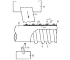
このように、成形回転軸20上において一定長さのホース主体1と拡径口元部分2'とを交互に連続して形成しながら成形回転軸20上を前方に向かって移動させ、引き続いて、図4に示すように、成形回転軸20の前端側に送り出したホース主体1と拡径口元部分2'を、成形回転軸20の外側方に配設している冷却装置25から噴射される冷却水によって冷却して硬化させたのち、さらに前進させて成形回転軸20の前端側外周方に配設している回転切断刃26によりその拡径口元部分2'の長さ方向の中央部を順次、全周に亘って切断する。
【0035】
回転切断刃26は拡径口元部分2'の外周面から拡径口元部成形部材7の外周面に達するまで切り込まれ、従って、拡径口元部分2'は前側のホース主体1の後端に連らなった拡径口元部2と、後側のホース主体1の前端に連なった拡径口元部2とに二分割される。拡径口元部分2'の分割後、前側のホース主体1を成形回転軸20からこの成形回転軸20の軸芯延長方向に引き抜くと、分割された拡径口元部2、2間が分離してホース主体1の両端部に上記拡径口元部分2'の1/2の長さを有する拡径口元部2、2を一体に設けてなる合成樹脂製ホースAが得られるものである。
【0036】
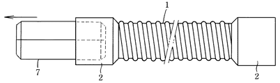
この時、拡径口元部成形部材7は二分割された拡径口元部2、2のいずれか一方の拡径口元部2にその長さ方向の一半部を挿嵌し、他半部を該拡径口元部2から突出させた状態で残存してあり、この拡径口元部成形部材7を図5に示すように拡径口元部2から引き抜いたのち、再び、成形回転軸20の基端部側におけるホース製造部に供給して上記同様に成形回転軸20上に被せ、拡径口元部分2'の成形に使用するものである。
【0037】
こうして得られた合成樹脂製ホースAは、図1(イ)に示すように、内周面が全長に亘って同一径の平滑(平坦)な面3に形成している管壁1aの外周面に補強螺旋突条4を一体に形成してなる所定長さのホース主体1の両端部に、内径が該ホース主体1の管壁1aの内径よりも大径に形成された肉厚の拡径口元部2、2を一体に設けた構造を有し、且つ、拡径口元部2、2はその内部に上記補強螺旋突条4を形成している合成樹脂製補強芯線4bの小径補強芯線4b' がホース主体1側から連続した状態で螺旋状に埋設した構造を有している。
【0038】
なお、上記合成樹脂製ホースの製造方法において、拡径口元部成形部材7としては、一部分を全長に亘って切断して互いに密接した対向端面93、94を形成し、この対向端面93、94間を拡げることによって成形回転軸20上に装着するように形成した成形部材を使用しているが、図7に示すように、長さが形成すべき拡径口元部2の二倍の長さを有し、且つ前後両端部の外周面を端面に向かうに従って徐々に小径となるテーパ面91、92に形成してなる半筒形状の成形部材一半片7A1 と半筒形状の成形部材他半片7A2 とから円筒形状の拡径口元部成形部材7Aを構成してもよい。
【0039】
この場合、成形部材一半片7A1 と他半片7A2 との接合端面95、96の何れか一方に数個の小径の係合孔97を、他方にこの係合孔97に係脱可能に挿嵌させる突起体98を設けておき、これらの成形部材一半片7A1 と他半片7A2 とを成形回転軸20の基端部における外周面に被せて突起体98を係合孔97に挿嵌させることにより相対する端面95、96を接合させ、円筒形状の拡径口元部成形部材7Aを組み立てるものである。なお、このような係合孔97と突起体98とによる成形部材一半片7A1 と他半片7A2 との接合手段以外に、いずれか一方の端面に蟻溝を、他方の端面にこの蟻溝に挿入、係止可能な突条部を形成しておく等の適宜な手段を採用してもよい。また、この成形部材一半片7A1 と他半片7A2 とは、ゴム製に限らず、アルミやアルミ合金等の金属製であってもよい。
【0040】
この拡径口元部成形部材7'を用いての拡径口元部2を有する合成樹脂製ホースの製造方法は上記実施例と同様であるので、その説明を省略する。また、いずれの合成樹脂製ホースの製造方法においても、所定長さのホース主体1を形成する毎に、同大、同形の上記拡径口元部成形部材7、7・・・又は、拡径口元部成形部材7A、7A・・・を成形回転軸20上に被せることによってこれらの拡径口元部成形部材7又は7A上に同一厚みで同一内外径の拡径口元部分2'を順次形成し、この拡径口元部分2'を二分割することにより図1(イ)に示すように、両端部に同大、同形の拡径口元部2、2を有する合成樹脂製ホースAを製造しているが、図1(ロ)に示すように、ホース主体1の両端部に連なった拡径口元部2、2において、一方を大径拡径口元部2Aに、他方を小径拡径口元部2Bに形成した合成樹脂製ホースA'を得るには、上記同大、同形の拡径口元部成形部材7又は7Aに代えて、異なった外径を有する拡径口元部成形部材7B、7Cを使用すればよい。
【0041】
即ち、図8に示すように、上記合成樹脂ホースの製造時において、成形回転軸20上に第1成形ノズル21からの薄肉の半溶融状態の合成樹脂製帯状材11を螺旋巻きすることによって所定長さのホース主体1を形成する毎に、外径が大径の拡径口元部成形部材7Bと外径がこの成形部材7Bよりも小径の拡径口元部成形部材7Cとを交互に成形回転軸20上に被せ、これらの拡径口元部成形部材7B、7C上に上記ホース主体1の形成に引き続いて第1成形ノズル21からの肉厚の半溶融状態の合成樹脂製帯状材11' を順次螺旋巻きすることによって一定厚みを有する円筒形状の大径の拡径口元部分2A' と小径の拡径口元部分2B' をそれぞれ形成したのち、これらの拡径口元部分2A' 、2B' を二分割すればよく、二分割後に拡径口元部成形部材7B、7Cを分割された拡径口元部から引き抜くことによってホース主体1の両端部にそれぞれ大径の拡径口元部2Aと小径の拡径口元部2Bを有する合成樹脂ホースA'を得ることができる。
【0042】
なお、上記大小径の拡径口元部成形部材7B、7Cの構造は、図6で示した拡開可能な接合端面93、94を有する円筒形状のゴム製からなる構造、或いは、図7で示した一半片7A1 と他半片7A2 とからなる構造を採用しており、上記大径拡径口元部部分2A' と小径拡径口元部分2B' とは、その長さ方向の中央部を回転切断刃26により切断されてホース主体1の一端部に大径の拡径口元部2Aを、他端部に小径の拡径口元部2Bをそれぞれ形成した図1(ロ)に示す合成樹脂製ホースA'を得るものであるが、他端側の拡径口元部2Bの外径は一端側の拡径口元部2Aの外径よりも小径であっても、内径は、ホース主体1の内径よりも成形回転軸20上に被せる小径の拡径口元部成形部材7Cの厚み分だけ大径に形成されている。また、大径の拡径口元部成形部材7Bはその厚みが大きいので、例えば、前後両端部を除く内周面側を切除して薄く形成しておいてもよい。
【0043】
また、上記拡径口元部成形部材7、7A、7B、7Cに代えて、図9に示すように、長さが拡径口元部2の長さに等しい半円筒形状の割型片71、71を分割可能に組み合わせてなる円筒形状の成形部材一半部7'と、同じく長さが拡径口元部2の長さに等しい半円筒形状の割型片72、72を分割可能に組み合わせてなる円筒形状の成形部材他半部7'' とからなる拡径口元部成形部材7Dを用いてもよい。
【0044】
なお、図示していないが、割型片71、71及び72、72との対向端面と、これらの割型片によって形成される成形部材一半部7'と他半部7'' との対向端面には、上述したような係合孔と突起体等からなる接合手段によって分離可能に連結するように形成されている。
【0045】
このように形成した拡径口元部成形部材7Dを成形回転軸20上に装着するには、半円筒形状の割型片71、71を組み合わせて円筒形状の成形部材一半部7'に形成しながら成形回転軸20に被嵌させ、同様に半円筒形状の割型片72、72を組み合わせて円筒形状の成形部材一半部7'' に形成しながら成形回転軸20に被嵌させて成形部材一半部7'の後端接合部を成形部材他半部7'' の前端受け口部に突き合わせ状に接合するか、或いは、図10に示すように、成形部材一半部7'と他半部7'' との一方の割型片71、72同士と他方の割型片71、72同士をそれぞれ組み合わせたのち、これらの割型片71、72を成形回転軸20上で円筒形状となるように接合させることにより行うことができる。
【0046】
成形回転軸20の基端部上に装着した拡径口元部成形部材7Dは、上記合成樹脂製ホースの製造方法と同じく、送りローラ23、23によって第1成形ノズル21によるホース製造部にまで前方に送り込まれ、成形回転軸20上に第1成形ノズル21からの半溶融状態の薄肉合成樹脂製帯状材11を螺旋巻きすることによって製造された合成樹脂製ホース主体1の後端に突き合わせ状に接合させられてこの外周面に、第1成形ノズル21からの肉厚の半溶融状態の薄肉合成樹脂製帯状材11' を連続的に螺旋状に巻回することにより、拡径口元部分2'を形成していくと共に、第2成形ノズル22からは半溶融状態の大小径の合成樹脂製補強芯線4b、4b' をそれぞれホース主体1の管壁外周面と拡径口元部分2'内とに螺旋状に配設する。
【0047】
そして、成形回転軸20上において一定長のホース主体1を形成される毎に拡径口元部成形部材7Dを供給することにより一定長のホース主体1と拡径口元部分2'とを交互に連続して形成しながら成形回転軸20上を前方に送って冷却装置25により冷却し、しかるのち、回転切断刃26によってその拡径口元部分2'の長さ方向の中央部を全周に亘って切断する。
【0048】
この時、回転切断刃26は図11に示すように、拡径口元部分2'の外周面から拡径口元部成形部材7Dの外周面に達するまで切り込まれ、且つその切り込み個所は拡径口元部成形部材7Dの成形部材一半部7'と他半部7'' との接合部である。従って、拡径口元部分2'の分割後、前側のホース主体1を成形回転軸20からこの成形回転軸20の軸芯延長方向に引き抜くと、拡径口元部成形部材7Dの一半部7'と他半部7'' とが分離してホース主体1の両端部に上記拡径口元部分2'の1/2の長さを有する拡径口元部2、2を一体に設けてなる合成樹脂ホースAが得られる。
【0049】
こうして、得られた合成樹脂製ホースAの両端側の拡径口元部2、2内には、成形部材一半部7'と他半部7'' とがそれぞれ内嵌状態で収納されてあり、これらの成形部材一半部7'と他半部7'' とを拡径口元部2、2から抜き取ったのち、再び、成形回転軸20の基端部側におけるホース製造部に送り、上記同様にこれらの成形部材一半部7'と他半部7'' との割型片71、72を組み合わせて円筒形状の拡径口元部成形部材7Dを形成するものである。
【0050】
なお、この拡径口元部成形部材7Dにおいても、小径の拡径口元部成形部材と大径の拡径口元部成形部材とに形成しておき、これらの大小径の拡径口元部成形部材によって上述したようにホース主体1の両端部に大径の拡径口元部2Aと小径の拡径口元部2Bとをそれぞれ設けてなる合成樹脂製ホースを製造し得るのは勿論である。
【0051】
次に、上記のように形成している可撓性を有する軟質合成樹脂製ホースA、A'の使用の一例としては、例えば、図12(a)に示すように、硬質合成樹脂製管B、Bを地中等に敷設する場合にこれらの硬質合成樹脂製管B、Bの対向端部間を接続するのに使用される。即ち、上記硬質合成樹脂管B、Bが同一径を有する場合には両端に同一内外径の拡径口元部2、2を有する軟質合成樹脂製ホースAを用いてこの拡径口元部2、2にそれぞれ対向する硬質合成樹脂製管B、Bの端部をパッキン等を介して挿嵌することにより連結、連通させる。
【0052】
また、上記硬質合成樹脂製管B1、B2の径が異なる場合には図12(b)に示すように、両端にこれらの硬質合成樹脂製管B1、B2の端部を挿嵌させることができる内径に形成された大径の拡径口元部2Aと小径の拡径口元部2Bを有する軟質合成樹脂製ホースA'を用い、大径の拡径口元部2Aに大径の合成樹脂製管B1の端部を、小径の拡径口元部2Bに小径の合成樹脂管B2の端部をそれぞれパッキン等を介して挿嵌することにより連結、連通させればよい。
【0053】
いずれの場合においても、硬質合成樹脂B(B1)、B(B2)が互いに一直線状に施工されていなくても、軟質合成樹脂製ホースA、A'のホース主体1部分を湾曲、或いは、撓ませてその両端の拡径口元部2(2A)、2(2B)にそれぞれ対向する硬質合成樹脂製管B(B1)、B(B2)の端部を挿嵌させて正確且つ簡単に接続させることができ、その接続部においても流体円滑に流通させることができる管路を構成し得ると共に地震が発生しても、その振動を可撓性を有する軟質合成樹脂製ホースA、A'のホース主体1部分によって吸収して所定の接続構造を維持することができる。また、この軟質合成樹脂製ホースA、A'は、台所や洗面台等の排水口と屋外の排水管との接続用ホースとして使用した場合、上述した地中配管と同様に、施工が極めて容易に且つ確実に行えると共に排水性も良好であり、その上、優れた耐久性、耐震性を発揮することができる。さらに、小径の拡径口元部2Bを大径の拡径口元部2Aにパッキン等を介して挿嵌させることにより、可撓性を有する合成樹脂製ホースA'、A'同士を接続することもできる。
【0054】
図13、図14は、上記合成樹脂製ホースA、A'の別な製造方法を示すもので、上記実施例で述べたホース製造方法においては、ホース主体1に連なる拡径口元部分2'(2A')(2B')を2分割するには回転切断刃26によって行っているが、この製造方法においては回転切断刃26を使用することなく、上記拡径口元部成形部材7〜7Dに分断刃部を一体に設けてなる拡径口元部成形部材7Eによって行っているものである。なお、この実施例では、ホース主体1の両端部に同大、同形の拡径口元部2、2を形成するための拡径口元部成形部材7Eを使用している場合について以下に説明するが、ホース主体1の両端部に互いに異なる径の拡径口元部2A、2Bを形成する場合も、上記拡径口元部係合7Eとして上記実施例で述べた大径成形部材と小径成形部材に分断刃部を設けた形状のものを使用すればよい。
【0055】
この拡径口元部成形部材7Eは図13に示すように、上記製造方法において用いた長さが形成すべき拡径口元部2の二倍の長さを有し、且つ前後両端部の外周面を端面に向かうに従って徐々に小径となるテーパ面91、92に形成してなる金属製の半筒形状の成形部材一半片7A1 と同じく金属製の半筒形状の成形部材他半片7A2 とからなり、これらの一半片7A1 と他半片7A2 との長さ方向の中央部外周面に高さが拡径口元部成形部材7E上に形成される拡径口元部分2'の厚みに等しい先端が尖鋭な分断刃部73を全周に亘って突設してなるものである。
【0056】
このように構成した拡径口元部成形部材7Eを用いて上記合成樹脂製ホースAを製造するには、成形回転軸20上に上記製造方法と同じく、第1成形ノズル21から押し出される一定幅を有する半溶融状態の軟質合成樹脂製帯状材11を一定のピッチでもって螺旋巻きしながら管壁1aを形成していくと共に、この管壁1aの形成途上において、第2成形ノズル22から一定径を有する半溶融状態のポリエチレン、ポリプロピレン等の合成樹脂製補強芯線4bを押し出しながら先に巻回した上記合成樹脂製帯状材部11a 上に螺旋状に巻回し、この補強芯線4b上に次に巻回する合成樹脂帯状材部11b を被せることによって上記管壁1aの外周面に補強芯線4bを内装した中空螺旋突条4aを形成してなるホース主体1を製造していく。
【0057】
そして、所定長さのホース主体1が製造されると、図13に示すように、このホース主体1の後端に拡径口元部成形部材7Eを接続させてこの拡径口元部成形部材7E上に第1成形ノズル21から押し出される半溶融状態の合成樹脂製帯状材11の厚みを大きくしながら該肉厚の帯状材11' を螺旋巻きすると共に第2成形ノズル22から押し出される半溶融状態の合成樹脂製補強芯線4bを小径にしながらこの小径補強芯線4b' を上記帯状材11' に埋設されるように螺旋巻きすることによって肉厚の円筒形状の拡径口元部分2'を形成していく。
【0058】
なお、この拡径口元部成形部材7Eを所定長さに成形されたホース主体1の後端に向かって成形回転軸20上を滑動させながら送り込むには、成形回転軸20の基端部外周三方に配設した外周に螺旋溝8aを全長に亘って形成している回転送り軸8によって行う。即ち、これらの回転送り軸8の螺旋溝8aの一部を上記拡径口元部成形部材7Eの中央部に突設している分断刃部73に係合させた状態にして回転させることにより行われる。
【0059】
こうして、拡径口元部成形部材7Eは、回転送り軸8によって成形回転軸20上を上記第1成形ノズル21によるホース製造部にまで前方に送り込まれ、所定長さに製造された上記合成樹脂製ホース主体1の後端に突き合わせ状に接合させられる。そして、第1成形ノズル21から押し出されて合成樹脂製ホース主体1の後端部を製造中の上記半溶融状態の合成樹脂製帯状材11は、その厚みを大きくして押し出されながら拡径口元部成形部材7Eの前端の外周テーパ面91側から拡径口元部成形部材7Eの外周面に連続螺旋状に巻回してホース主体1の管壁1aの数倍の厚みを有し、且つ該ホース主体1の拡径口元部2の2倍の長さを有する肉厚の円筒状拡径口元部分2'を形成していくと共に上記第2成形ノズル22からは半溶融状態の合成樹脂製補強芯線4bが小径に成形されながら押し出されて拡径口元部成形部材7Eに螺旋巻きされる半溶融状態の合成樹脂製帯状材11' 内に埋設され、さらに、この拡径口元部2'の外周面は転圧ローラ24によって押圧されて平坦な面に成形される。
【0060】
この拡径口元部2'の形成中において、拡径口元部成形部材7E上に半溶融状態の肉厚帯状材11' を螺旋巻きする際に、分断刃部73によって全周に亘り切り込まれて2分されながら該分断刃部73上を通過する。こうして、拡径口元部成形部材7Eの外周面に半溶融状態の肉厚合成樹脂製帯状材11' を螺旋巻きすることによって一定厚みの拡径口元部分2'を形成しながら成形回転軸20上をホース本体1と一体に前方に移動する該拡径口元部成形部材7Eの進行に伴って該肉厚帯状材11' が拡径口元部成形部材7Eの後端テーパ面92に達すると、再び成形回転軸20上に連続的に螺旋巻きして上述したように外周面に補強螺旋突条4を設けたホース主体1を形成していく。この時、図14に示すように拡径口元部成形部材7Eの後端テーパ面92から成形回転軸20上に螺旋巻きする第1成形ノズル21からの半溶融状態の帯状材11は再び、その厚みを小さくした状態で押し出されながら且つ第2成形ノズル22からは半溶融状態の補強芯線を元の大径芯線4bとして押し出しながらホース主体1を形成しているものである。
【0061】
このように、成形回転軸20上において一定長さのホース本体1と円筒形状の拡径口元部分2'とが交互に連続して形成されると共に成形回転軸20の先端側に送り出されたホース本体1と拡径口元部2'は成形回転軸20の外側方に配設している冷却装置25から噴射される冷却水によって冷却されて硬化し、次いで、ホース本体1を成形回転軸20からホース本体1の進行方向に向かって引き抜くと、拡径口元部分2'の長さ方向の中央部が拡径口元部成形部材7Eの分断刃部73によって、切断されているので、この分断箇所から拡径口元部分2'が二分してホース本体1の両端部に拡径口元部2、2を一体に形成してなる合成樹脂製ホースAが得られる。
【0062】
なお、拡径口元部成形部材7Eは拡径口元部2から抜き取ったのち、再び、成形回転軸20の基端部側におけるホース製造部側に送られて上記同様に成形回転軸20上で割型片71、72を組み合わせて円筒形状の拡径口元部成形部材7Eに形成するものである。
【0063】
この拡径口元部成形部材7Cの外周面に突設している上記分断刃部73は、その基端から先端に向かって前後側面を緩やかに湾曲した傾斜面に形成されているのでホース主体1の拡径口元部2、2の開口端面がラッパ状に拡開した形状となり、従って、この拡径口元部2内への管体端部の挿嵌、接続作業が容易に行うことができる。
【0064】
なお、外周面に分断刃部73を一体に設けている拡径口元部成形部材7Eとして、大径の成形部材と小径の成形部材とを用いることにより、上記同様にして、ホース主体1の両端部に大径の拡径口元部2Aと小径の拡径口元部2Bとを有する合成樹脂製ホースA'を製造することができるのは勿論である。
【0065】
【発明の効果】
以上のように本発明の軟質合成樹脂製ホースの製造方法は、請求項1に記載したように、成形回転軸上に半溶融状態の合成樹脂製帯状材を重合、溶着させながら一定のピッチでもって螺旋巻きすることにより、内面が全長に亘って同一径の所定長さのホース主体を形成するホース主体成形工程と、このホース主体の成形工程に後続して上記成形回転軸に内径が成形回転軸の外径に等しい円筒形状の拡径口元部成形部材を成形回転軸の長さ方向に摺動移動可能に被せてこの拡径口元部成形部材上に上記半溶融状態の合成樹脂製帯状材を重合、溶着させることにより一定厚みを有する拡径口元部分を形成する口元部成形工程とからなり、上記ホース主体成形工程と拡径口元部分成形工程とを交互に行ったのち、拡径口元部分を長さ方向の中央部から分断すると共に拡径口元部成形部材を分断した上記拡径口元部分から抜き取ることにより、一定長さのホース主体の両端部に上記拡径口元部分の半分の長さを有する拡径口元部を設けた合成樹脂製ホースを得ることを特徴とするものであるから、ホース主体の両端部にこのホース主体と同一の軟質合成樹脂によって拡径口元部を設けてなる合成樹脂製ホースを連続的に能率よく製造することができて製品コストの低減を図ることができる。
【0066】
その上、成形回転軸上に拡径口元部成形部材を被せる間隔を変更することによってホース主体の長さを所望の長さとなるように自由に設定することができると共に、ホース主体の両端に拡径口元部成形部材の外径に応じた内径を有する拡径口元部を精度よく形成することができる。さらに、分断された拡径口元部分から抜き取った拡径口元部分形部材は再び、成形回転軸上に配設してその外周面にホース主体に連なる拡径口元部分の形成に使用することができ、従って、ホース主体の両端に形成される拡径口元部の形状にバラツキを生じさせることなく、品質的に均一な合成樹脂製ホースを製造することができる。
【0067】
上記合成樹脂製ホースの製造方法において、請求項2に係る発明は、ゴム質材によって円筒形状の拡径口元部成形部材を形成し、この拡径口元部成形部材の一部を全長に亘って切断してその切断面から弾性的に拡開させることにより成形回転軸上に装着するように形成しているので、成形回転軸に対するこの拡径口元部成形部材の装着作業がワンタッチで且つ確実に行えるのは勿論、成形回転軸上に半溶融状態の合成樹脂製帯状材を螺旋巻きすることによって成形されるホース主体が所望長さに達する毎に、正確に該ホース主体に後続させることができ、この成形部材の外周面にホース主体の端部を形成中の上記合成樹脂製帯状材を連続的に螺旋巻きさせて拡径口元部を円滑に形成することができる。
【0068】
また、成形回転軸上でホース主体とこの拡径口元部成形部材上での拡径口元部分との成形を行ったのち、拡径口元部分をその長さ方向の中央部から二分割し、しかるのち、ホース主体を成形回転軸上から引き抜くと、拡径口元部成形部材が分割した拡径口元部のいずれか一方に残存させることができ、この拡径口元部から突出している部分を引っ張ることによって簡単に引き抜くことができ、再び、成形回転軸上に装着して拡径口元部分の成形に使用することができる。
【0069】
一方、請求項3に記載の拡径口元部成形部材においては、ホース主体の両端部に形成される拡径口元部の二倍の長さを有する半筒形状の成形部材一半片と半筒形状の成形部材他半片とを組み合わせることによって円筒形状の拡径口元部成形部材を形成するように構成しているので、成形回転軸上に対するこの拡径口元部成形部材の配設作業が上記拡径口元部成形部材と同様に容易に且つ正確に行えると共に、この拡径口元部成形部材一半片と他半片とをアルミ等の金属材料によって形成しておくことにより、内外周面を極めて平滑な面に加工することができ、精度のよい拡径口元部を形成することができる。
【0070】
さらに、請求項4に係る発明によれば、成形回転軸上で所定長さのホース主体を形成する毎に、外径の異なる拡径口元部成形部材を交互に成形回転軸上に装着するものであるから、ホース主体の両端部に内径の異なる拡径口元部を有する合成樹脂製ホースを上記製造方法と同じ方法によって簡単に製造することができると共に、同大、同形の拡径口元部成形部材を必要に応じて使用して、同一製造工程中で所望長さのホース主体の両端部に同大、同形の拡径口元部を有する合成樹脂製ホースや、異なった径の拡径口元部を有する合成樹脂製ホースを連続的に能率よく製造することができる。
【図面の簡単な説明】
【図1】 (イ)及び(ロ)は軟質合成樹脂製ホースの一部縦断側面図、
【図2】 ホース主体を形成している状態の一部を断面した簡略側面図、
【図3】 拡径口元部分を形成している状態を示す一部を断面した簡略側面図、
【図4】 冷却後に拡径口元部分を分断した状態を示す側面図、
【図5】 ホースの拡径口元部内から成形部材を抜き取る状態を示す側面図、
【図6】 拡径口元部成形部材の斜視図、
【図7】 別な構造に形成している拡径口元部成形部材の斜視図、
【図8】 ホース主体の両端部に大径拡径口元部と小径拡径口元部とを製造する方法を示す簡略側面図、
【図9】 拡径口元部成形部材の別な構造を示す分解斜視図、
【図10】 図9の拡径口元部成形部材を用いたホースの製造方法を示す一部を断面した簡略側面図、
【図11】 拡径口元部分を切断している状態の側面図、
【図12】 使用状態の一例を示す簡略側面図、
【図13】 別な製造方法を説明するための一部を断面した簡略側面図、
【図14】 拡径口元部からホース主体を連続的に製造している状態の側面図、
【図15】 従来例を示す側面図。
【符号の説明】
A 軟質合成樹脂製ホース
1 ホース主体
2、2A、2B 拡径口元部
2' 拡径口元部分
4 補強螺旋突条
7、7A、7B、7C、7D、7E 拡径口元部成形部材
11 軟質合成樹脂製帯状材
20 成形回転軸[0001]
BACKGROUND OF THE INVENTION
The present invention is a soft synthetic resin hose having flexibility in which a diameter-expanded mouth portion serving as a connection port is formed at both ends. of It relates to a manufacturing method.
[0002]
[Prior art]
As a hose made of soft synthetic resin such as vinyl chloride resin used for water supply, drainage hose, watering hose, etc., as shown in Fig. 15, the inner peripheral surface is a flat surface with the same diameter over the entire length. A hose is widely known in which a
[0003]
In order to manufacture such a soft synthetic resin hose, when a semi-molten synthetic resin strip having a certain width is spirally wound on a molding rotating shaft while being extruded from a forming nozzle, a preceding strip shape is formed. The
[0004]
[Problems to be solved by the invention]
However, when a soft synthetic resin hose manufactured by this method is cut into predetermined lengths to obtain a drainage hose of a certain length, this hose has an inner peripheral surface over the entire length between the openings at both ends. Are formed on a flat surface having the same diameter, and therefore, it is impossible to directly connect another hose or the end of a pipe body having an inner diameter equal to the inner diameter of the hose in the opening end. . For this reason, a connection port member such as a nipple is inserted and fixed to the opening end of the hose, but the water passage hole penetrating through the center of the connection port member is formed to be smaller than the inner diameter of the hose. As a result, there arises a problem that the flow resistance increases and smooth drainage and water supply cannot be performed.
[0005]
Further, the central water passage hole of the connection port member is formed to have a diameter equal to the inner diameter of the soft synthetic resin hose, and the end portion of the connection port member is formed as a large diameter mouth portion. If it is attached in a state of being fitted on the outer peripheral surface of the opening end of the synthetic resin hose, the central water passage hole of the connection port member can be communicated with the inner diameter of the soft synthetic resin hose in a flush manner. Since the reinforcing spiral protrusion is provided across the outer peripheral surface of the soft synthetic resin hose across the both ends, when the opposite ends of the hose are connected to each other by the connection port member, the end of the connection port member Since the reinforcing spiral ridge is fitted to the peripheral surface, water leakage occurs through the spiral groove between the spiral ridges. For this reason, an appropriate filler is embedded in the spiral groove and the end of the hose After forming the outer peripheral surface into a flat surface, the end of the connection port member Must let inner fitting, there is a problem that products takes the trouble in the mounting work of the connecting port member increases costs.
[0006]
Furthermore, when using it as a short drainage hose for connecting a drainage outlet such as a kitchen or a wash basin and an outdoor drainage pipe, both ends are formed in the same cross-sectional shape as the middle part of the hose as described above. Therefore, it must be connected using another connection port member.
[0007]
The present invention has been made in view of such problems, and the object of the present invention is to have flexibility that allows connection so that water-tight and smooth circulation is possible without using a connection port member. Synthetic resin hose The It is in providing the manufacturing method which can manufacture efficiently.
[0008]
[Means for Solving the Problems]
In order to achieve the above object, a synthetic resin hose having an enlarged-diameter mouth portion according to
[0009]
[0010]
And claims 3 The invention according to the present invention is an enlarged-diameter base part molding member having another shape, and the enlarged-diameter base part molding member has twice the length of the enlarged-diameter base part formed at both ends of the hose main body. It consists of a half-cylindrical shaped member half and a half-cylindrical shaped member other half, and these one half and other half are combined and detachably mounted on the molding rotating shaft.
[0011]
Claims above 1 To claims 3 In the invention described in
[0012]
[Action]
A semi-molten soft synthetic resin strip material is spirally wound on a rotating part of the molding material while the opposite portion of the strip material portion to be wound next is superposed and welded to a part of the previously wound belt material portion. Thus, the tube wall mainly composed of the hose is continuously formed. At this time, a reinforcing spiral protrusion may be formed by winding a core wire in a spiral shape around the outer peripheral surface of the tube wall and covering the core wire with the synthetic resin strip. As the hose main body is formed, the hose main body is sent along the length of the rotating shaft to be cooled.
[0013]
In this way, when a hose main body having a predetermined length is formed in the course of forming the hose main body by spirally winding a semi-molten synthetic resin strip on the molding rotating shaft, the hose main body is followed. Then, the cylindrical enlarged diameter mouth portion member is covered on the molding rotating shaft, and the end portion of the hose main body is formed from the above-mentioned semi-molten synthetic resin belt-like material, and the enlarged diameter mouth portion shaping member is formed from the end portion. A semi-molten synthetic resin strip is continuously spirally wound to form a cylindrical enlarged diameter mouth portion having a predetermined thickness and length larger than that of the hose main body.
[0014]
The diameter-enlarged mouth portion molding member is formed on the rotating shaft together with a hose main body of a predetermined length previously formed by the synthetic resin strip material while the semi-molten synthetic resin strip material is spirally wound around the outer peripheral surface thereof. The semi-molten synthetic resin strip is spirally wound on the expanded diameter part forming member to form a cylindrical expanded diameter part continuous with the hose main body. When reaching the end of the mouth part molded member, the semi-molten synthetic resin strip is continuously spirally wound from the end part onto the molding rotating shaft, and the hose main body connected to the enlarged diameter mouth part is formed. Further, when the hose main body is formed to a predetermined length, the rear end of the hose main body is covered in the same manner as described above on the diameter-expanded mouth part molding member by covering the molding rotating shaft with the next diameter-expanding mouth part molding member. A diameter-enlarged mouth portion that is continuous with the outer diameter is formed.
[0015]
As described above, while the hose main body molding process of a predetermined length and the cylindrical diameter expansion mouth part molding process integrally connected to the end of the hose main body are alternately and continuously performed on the molding rotating shaft, Made of a synthetic resin with a fixed length that is formed by integrating the enlarged diameter mouth part at both ends by dividing the enlarged diameter mouth part cooled at the front part on the molding rotating shaft sequentially from the central part in the length direction. Obtain the hoses sequentially.
[0016]
After the cylinder-shaped diameter-enlarged mouth portion formed on the diameter-enlarged mouth portion is divided into two parts, when the hose main body is pulled out from the molding rotating shaft, the diameter-enlarged mouth-portion molded member remains in the diameter-enlarged mouth portion. The hose formed by spirally winding a semi-molten synthetic resin strip-like material on the molded rotating shaft, which is pulled out from the expanded diameter mouth portion, returned to the hose manufacturing portion side of the molded rotating shaft. A cylindrical enlarged diameter mouth portion having a diameter larger than that of the hose main body is formed on the outer peripheral surface continuously with the main molding step.
[0017]
Thus, the manufactured synthetic resin hose has an inner peripheral surface in which the inner diameter made of the same resin as the hose main body is larger than the inner diameter of the hose main body at both ends of the flexible hose main body having a certain length. Has an enlarged-diameter base part formed on a smooth surface by the outer peripheral surface of the above-mentioned enlarged-diameter base part forming member, and this enlarged-diameter base part is used as a connection port with a hose or a tubular body.
[0018]
DETAILED DESCRIPTION OF THE INVENTION
Next, specific embodiments of the present invention will be described with reference to the drawings. FIGS. 1 (a) and 1 (b) are olefin resins such as EVA resin, polyethylene, and polypropylene resin, or soft resins such as vinyl chloride resin. Synthetic resin hoses A and A ′, which are formed by integrally forming thickened enlarged
[0019]
The reinforcing
[0020]
On the other hand, the base end portions of the enlarged
[0021]
In the synthetic resin hoses A and A ′ configured as described above, the synthetic resin hose A shown in FIG. 1 (b) has the same diameter-enlarged
[0022]
That is, these enlarged
[0023]
Also, by making the inner diameter of the large diameter enlarged
[0024]
Next, a method for producing the synthetic resin hoses A and A ′ formed as described above will be described. First, as shown in FIG. 2, a soft synthetic material such as a semi-molten soft vinyl chloride resin having a certain width is used. As is well known, the
[0025]
In this way, by winding the semi-molten soft
[0026]
As shown in FIGS. 3 and 6, the above-mentioned
[0027]
The diameter-enlarged mouth
[0028]
In order to mount the diameter-enlarged mouth
[0029]
The diameter-enlarged mouth
[0030]
At this time, the semi-molten
[0031]
That is, when the semi-molten synthetic resin strip 11 'is spirally wound around the outer peripheral surface of the diameter-enlarged mouth
[0032]
In this way, a semi-molten thick synthetic resin strip 11 'is spirally wound around the outer peripheral surface of the enlarged diameter
[0033]
When the hose
[0034]
In this way, the hose
[0035]
The
[0036]
At this time, the enlarged-diameter mouth
[0037]
In the synthetic resin hose A thus obtained, the outer peripheral surface of the tube wall 1a formed on the smooth (flat)
[0038]
In the synthetic resin hose manufacturing method described above, the diameter-enlarged mouth
[0039]
In this case, several small-diameter engagement holes 97 are inserted into either one of the joining end surfaces 95, 96 of the molded member half piece 7A1 and the other half piece 7A2, and the other is detachably inserted into the
[0040]
Since the manufacturing method of the synthetic resin hose having the enlarged-
[0041]
That is, as shown in FIG. 8, at the time of manufacturing the synthetic resin hose, a thin, semi-molten
[0042]
Note that the structure of the large and small diameter enlarged diameter
[0043]
Further, in place of the above-mentioned diameter-enlarged mouth
[0044]
Although not shown, the opposed end surfaces of the
[0045]
In order to mount the diameter-enlarged mouth
[0046]
The diameter-enlarged mouth
[0047]
Then, each time a constant length hose
[0048]
At this time, as shown in FIG. 11, the
[0049]
Thus, in the enlarged
[0050]
In addition, in this enlarged diameter mouth
[0051]
Next, as an example of the use of the flexible synthetic resin hoses A and A ′ having flexibility formed as described above, for example, as shown in FIG. , B is used to connect the opposite ends of the hard synthetic resin pipes B, B when laying in the ground or the like. That is, when the hard synthetic resin pipes B and B have the same diameter, the diameter-expanded
[0052]
When the diameters of the hard synthetic resin pipes B1 and B2 are different, as shown in FIG. 12B, the ends of these hard synthetic resin pipes B1 and B2 can be inserted into both ends. Using a soft synthetic resin hose A 'having a large diameter enlarged
[0053]
In any case, even if the hard synthetic resins B (B1) and B (B2) are not installed in a straight line with each other, the soft synthetic resin hoses A and A 'hose
[0054]
FIG. 13 and FIG. 14 show another manufacturing method of the synthetic resin hoses A and A ′. In the hose manufacturing method described in the above embodiment, the diameter-enlarged
[0055]
As shown in FIG. 13, the diameter-enlarged mouth
[0056]
In order to manufacture the synthetic resin hose A using the diameter-enlarged mouth
[0057]
Then, when the hose
[0058]
In order to feed the diameter-enlarged mouth
[0059]
In this manner, the diameter-enlarged mouth
[0060]
During the formation of the enlarged diameter portion 2 ', when the thick strip 11' in a semi-molten state is spirally wound on the enlarged diameter
[0061]
As described above, the
[0062]
In addition, after the diameter-enlarged mouth
[0063]
The
[0064]
In addition, by using a large-diameter molding member and a small-diameter molding member as the enlarged-diameter mouth
[0065]
【The invention's effect】
As described above, the soft synthetic resin hose of the present invention The manufacturing method of
[0066]
In addition, the length of the hose main body can be freely set to a desired length by changing the interval over which the diameter-enlarged mouth portion molding member is placed on the molding rotating shaft, and the hose main body can be expanded at both ends. A diameter-enlarged mouth portion having an inner diameter corresponding to the outer diameter of the diameter-portion portion molded member can be formed with high accuracy. Furthermore, the diameter-enlarged mouth part-shaped member extracted from the divided diameter-enlarged mouth part can be used again to form the diameter-enlarged mouth part connected to the hose main body on the outer peripheral surface of the member. Therefore, a synthetic resin hose that is uniform in quality can be manufactured without causing variations in the shape of the enlarged-diameter mouth portion formed at both ends of the hose main body.
[0067]
In the manufacturing method of the synthetic resin hose,
[0068]
In addition, after forming the hose main body and the diameter-expanded mouth part on the diameter-expanded mouth part on the molding rotation shaft, the diameter-expanded mouth part is divided into two parts from the center in the length direction. After that, when the hose main body is pulled out from the molding rotating shaft, it can be left in either one of the enlarged diameter mouth parts divided by the enlarged diameter mouth part molding member, and the portion protruding from the enlarged diameter mouth part is pulled. Can be easily pulled out and mounted again on the molding rotating shaft and used for molding the diameter-enlarged mouth portion.
[0069]
Meanwhile, claims 3 In the diameter-enlarged mouth portion molding member described in 1), a half-cylindrical molded member half piece and a half-cylindrical shaped member other half piece having twice the length of the enlarged diameter mouth portion formed at both ends of the hose main body Is formed so as to form a cylindrical-shaped enlarged-diameter mouth part molding member. Similarly, the inner and outer peripheral surfaces can be processed into an extremely smooth surface by forming the half-diameter enlarged portion molding member half and the other half with a metal material such as aluminum. It is possible to form an accurate diameter-expanded mouth portion.
[0070]
And claims 4 According to the invention according to the present invention, every time the hose main body having a predetermined length is formed on the molding rotating shaft, the enlarged-portion portion molding members having different outer diameters are alternately mounted on the molding rotating shaft. A synthetic resin hose having enlarged diameter base portions with different inner diameters at both ends of the main body can be easily manufactured by the same method as the above manufacturing method, and an enlarged diameter shaped mouth portion molding member of the same size and the same shape as required Used in the same manufacturing process, both ends of the hose main body of the desired length are made of synthetic resin hose having the same size and the same shape of the enlarged diameter mouth portion, and synthetic resin having enlarged diameter mouth portions of different diameters A hose can be manufactured continuously and efficiently.
[Brief description of the drawings]
FIG. 1 (a) and (b) Is soft A partially cutaway side view of a synthetic resin hose,
FIG. 2 is a simplified side view of a part of a state in which a hose main body is formed,
FIG. 3 is a simplified side view, partly in section, showing a state where an enlarged diameter mouth portion is formed;
FIG. 4 is a side view showing a state where the diameter-expanded mouth portion is divided after cooling;
FIG. 5 is a side view showing a state in which a molded member is extracted from the inside of the expanded diameter portion of the hose;
FIG. 6 is a perspective view of an enlarged diameter base portion molding member;
FIG. 7 is a perspective view of a diameter-enlarged mouth portion molding member formed in another structure;
FIG. 8 is a simplified side view showing a method for manufacturing a large-diameter enlarged diameter mouth portion and a small-diameter enlarged diameter mouth portion at both ends of the hose main body;
FIG. 9 is an exploded perspective view showing another structure of the enlarged diameter base portion molding member;
10 is a simplified side view showing a method of manufacturing a hose using the diameter-enlarged mouth portion molding member of FIG.
FIG. 11 is a side view showing a state in which the diameter-enlarged mouth portion is cut;
FIG. 12 is a simplified side view showing an example of a usage state;
FIG. 13 is a simplified side view, partly in section, for explaining another manufacturing method;
FIG. 14 is a side view showing a state in which a hose main body is continuously manufactured from an enlarged diameter base portion;
FIG. 15 is a side view showing a conventional example.
[Explanation of symbols]
A Soft plastic hose
1 Main hose
2, 2A, 2B Expanded mouth
2 'Expanded mouth part
4 Reinforcing spiral ridges
7, 7A, 7B, 7C, 7D, 7E Expanded mouth part
11 Strips made of soft synthetic resin
20 Molding axis
Claims (4)
Priority Applications (1)
| Application Number | Priority Date | Filing Date | Title |
|---|---|---|---|
| JP2001355167A JP3782002B2 (en) | 2001-01-18 | 2001-11-20 | Method for producing a synthetic resin hose having an enlarged diameter base |
Applications Claiming Priority (3)
| Application Number | Priority Date | Filing Date | Title |
|---|---|---|---|
| JP2001-10635 | 2001-01-18 | ||
| JP2001010635 | 2001-01-18 | ||
| JP2001355167A JP3782002B2 (en) | 2001-01-18 | 2001-11-20 | Method for producing a synthetic resin hose having an enlarged diameter base |
Publications (2)
| Publication Number | Publication Date |
|---|---|
| JP2002286172A JP2002286172A (en) | 2002-10-03 |
| JP3782002B2 true JP3782002B2 (en) | 2006-06-07 |
Family
ID=26607909
Family Applications (1)
| Application Number | Title | Priority Date | Filing Date |
|---|---|---|---|
| JP2001355167A Expired - Lifetime JP3782002B2 (en) | 2001-01-18 | 2001-11-20 | Method for producing a synthetic resin hose having an enlarged diameter base |
Country Status (1)
| Country | Link |
|---|---|
| JP (1) | JP3782002B2 (en) |
Families Citing this family (3)
| Publication number | Priority date | Publication date | Assignee | Title |
|---|---|---|---|---|
| JP2008256013A (en) * | 2007-04-02 | 2008-10-23 | Evuc Kk | Synthetic resin hose having joint portion at each end, and its manufacturing method |
| JP5078430B2 (en) * | 2007-05-16 | 2012-11-21 | アキレス株式会社 | Flexible pipe fittings |
| JP5631707B2 (en) * | 2010-12-01 | 2014-11-26 | 三桜工業株式会社 | Tube and tube manufacturing method |
-
2001
- 2001-11-20 JP JP2001355167A patent/JP3782002B2/en not_active Expired - Lifetime
Also Published As
| Publication number | Publication date |
|---|---|
| JP2002286172A (en) | 2002-10-03 |
Similar Documents
| Publication | Publication Date | Title |
|---|---|---|
| US3538209A (en) | Method of producing plastic tubing having a corrugated outer wall | |
| JP5155756B2 (en) | Apparatus for forming curl of strip-shaped member with reinforcing material, method for producing spiral tube, method for producing the same, and method for rehabilitating existing tube | |
| JP3868274B2 (en) | Method for producing synthetic resin hose having joints at both ends | |
| CS202541B2 (en) | Appliance for making the ribbed pipes from the plastic or other extruded material | |
| EP2000723A1 (en) | Fluid conducting pipe having rigid sections alternating with flexible sections | |
| JP3782002B2 (en) | Method for producing a synthetic resin hose having an enlarged diameter base | |
| JP5007165B2 (en) | Synthetic resin joint pipe and manufacturing method thereof | |
| JP6325366B2 (en) | Method and apparatus for manufacturing synthetic resin hose | |
| JP5350687B2 (en) | Manufacturing method of synthetic resin hose | |
| JP4567376B2 (en) | Lining construction method for existing pipe and pipe making machine used for the construction method | |
| JP2005214425A (en) | Synthetic resin-made hose having joint part in both end parts | |
| JP4357833B2 (en) | Manufacturing method of synthetic resin hose for pipe joint | |
| JP2002283433A (en) | Method for manufacturing tube | |
| JPH0628892B2 (en) | Method of manufacturing cladding tube with hollow spiral rib | |
| JP2003175547A (en) | Method and equipment for lining inside conduit | |
| JP5393019B2 (en) | Synthetic resin connecting pipe and its manufacturing method | |
| JP3222890B2 (en) | Extrusion die with replaceable extrusion nozzle | |
| JP2008256013A (en) | Synthetic resin hose having joint portion at each end, and its manufacturing method | |
| JP2000272007A (en) | Formation of spiral tube, self-traveling tube making machine and welding device | |
| JPS5831289B2 (en) | Manufacturing equipment for spirally corrugated plastic pipes | |
| JP5912301B2 (en) | Synthetic resin hose and its manufacturing method | |
| JPH0572852B2 (en) | ||
| JP4422859B2 (en) | Synthetic resin molding extrusion method and hose molding method | |
| JP2004190719A (en) | Flexible synthetic resin pressure-resistant pipe body for fitting | |
| RU2288841C2 (en) | Molding device having the molding ducted work tool making the reciprocating movement and capable to mold the products of the various configuration |
Legal Events
| Date | Code | Title | Description |
|---|---|---|---|
| A977 | Report on retrieval |
Free format text: JAPANESE INTERMEDIATE CODE: A971007 Effective date: 20050322 |
|
| A131 | Notification of reasons for refusal |
Free format text: JAPANESE INTERMEDIATE CODE: A131 Effective date: 20050705 |
|
| A521 | Written amendment |
Free format text: JAPANESE INTERMEDIATE CODE: A523 Effective date: 20050902 |
|
| TRDD | Decision of grant or rejection written | ||
| A01 | Written decision to grant a patent or to grant a registration (utility model) |
Free format text: JAPANESE INTERMEDIATE CODE: A01 Effective date: 20060207 |
|
| A61 | First payment of annual fees (during grant procedure) |
Free format text: JAPANESE INTERMEDIATE CODE: A61 Effective date: 20060308 |
|
| R150 | Certificate of patent or registration of utility model |
Free format text: JAPANESE INTERMEDIATE CODE: R150 Ref document number: 3782002 Country of ref document: JP Free format text: JAPANESE INTERMEDIATE CODE: R150 |
|
| S531 | Written request for registration of change of domicile |
Free format text: JAPANESE INTERMEDIATE CODE: R313531 |
|
| R350 | Written notification of registration of transfer |
Free format text: JAPANESE INTERMEDIATE CODE: R350 |
|
| FPAY | Renewal fee payment (event date is renewal date of database) |
Free format text: PAYMENT UNTIL: 20100317 Year of fee payment: 4 |
|
| R250 | Receipt of annual fees |
Free format text: JAPANESE INTERMEDIATE CODE: R250 |
|
| FPAY | Renewal fee payment (event date is renewal date of database) |
Free format text: PAYMENT UNTIL: 20100317 Year of fee payment: 4 |
|
| FPAY | Renewal fee payment (event date is renewal date of database) |
Free format text: PAYMENT UNTIL: 20110317 Year of fee payment: 5 |
|
| R250 | Receipt of annual fees |
Free format text: JAPANESE INTERMEDIATE CODE: R250 |
|
| FPAY | Renewal fee payment (event date is renewal date of database) |
Free format text: PAYMENT UNTIL: 20110317 Year of fee payment: 5 |
|
| R250 | Receipt of annual fees |
Free format text: JAPANESE INTERMEDIATE CODE: R250 |
|
| FPAY | Renewal fee payment (event date is renewal date of database) |
Free format text: PAYMENT UNTIL: 20120317 Year of fee payment: 6 |
|
| FPAY | Renewal fee payment (event date is renewal date of database) |
Free format text: PAYMENT UNTIL: 20130317 Year of fee payment: 7 |
|
| R250 | Receipt of annual fees |
Free format text: JAPANESE INTERMEDIATE CODE: R250 |
|
| FPAY | Renewal fee payment (event date is renewal date of database) |
Free format text: PAYMENT UNTIL: 20130317 Year of fee payment: 7 |
|
| FPAY | Renewal fee payment (event date is renewal date of database) |
Free format text: PAYMENT UNTIL: 20140317 Year of fee payment: 8 |
|
| R250 | Receipt of annual fees |
Free format text: JAPANESE INTERMEDIATE CODE: R250 |
|
| R250 | Receipt of annual fees |
Free format text: JAPANESE INTERMEDIATE CODE: R250 |
|
| R250 | Receipt of annual fees |
Free format text: JAPANESE INTERMEDIATE CODE: R250 |
|
| R250 | Receipt of annual fees |
Free format text: JAPANESE INTERMEDIATE CODE: R250 |
|
| R250 | Receipt of annual fees |
Free format text: JAPANESE INTERMEDIATE CODE: R250 |
|
| R250 | Receipt of annual fees |
Free format text: JAPANESE INTERMEDIATE CODE: R250 |
|
| R250 | Receipt of annual fees |
Free format text: JAPANESE INTERMEDIATE CODE: R250 |
|
| R250 | Receipt of annual fees |
Free format text: JAPANESE INTERMEDIATE CODE: R250 |
|
| R250 | Receipt of annual fees |
Free format text: JAPANESE INTERMEDIATE CODE: R250 |
|
| EXPY | Cancellation because of completion of term |