JP3780823B2 - Control device for electric power steering device - Google Patents
Control device for electric power steering device Download PDFInfo
- Publication number
- JP3780823B2 JP3780823B2 JP2000154284A JP2000154284A JP3780823B2 JP 3780823 B2 JP3780823 B2 JP 3780823B2 JP 2000154284 A JP2000154284 A JP 2000154284A JP 2000154284 A JP2000154284 A JP 2000154284A JP 3780823 B2 JP3780823 B2 JP 3780823B2
- Authority
- JP
- Japan
- Prior art keywords
- steering
- motor
- electric power
- power steering
- torque
- Prior art date
- Legal status (The legal status is an assumption and is not a legal conclusion. Google has not performed a legal analysis and makes no representation as to the accuracy of the status listed.)
- Expired - Fee Related
Links
Images


Classifications
-
- B—PERFORMING OPERATIONS; TRANSPORTING
- B62—LAND VEHICLES FOR TRAVELLING OTHERWISE THAN ON RAILS
- B62D—MOTOR VEHICLES; TRAILERS
- B62D5/00—Power-assisted or power-driven steering
- B62D5/04—Power-assisted or power-driven steering electrical, e.g. using an electric servo-motor connected to, or forming part of, the steering gear
- B62D5/0457—Power-assisted or power-driven steering electrical, e.g. using an electric servo-motor connected to, or forming part of, the steering gear characterised by control features of the drive means as such
- B62D5/046—Controlling the motor
- B62D5/0472—Controlling the motor for damping vibrations
-
- B—PERFORMING OPERATIONS; TRANSPORTING
- B62—LAND VEHICLES FOR TRAVELLING OTHERWISE THAN ON RAILS
- B62D—MOTOR VEHICLES; TRAILERS
- B62D5/00—Power-assisted or power-driven steering
- B62D5/04—Power-assisted or power-driven steering electrical, e.g. using an electric servo-motor connected to, or forming part of, the steering gear
- B62D5/0457—Power-assisted or power-driven steering electrical, e.g. using an electric servo-motor connected to, or forming part of, the steering gear characterised by control features of the drive means as such
- B62D5/046—Controlling the motor
- B62D5/0463—Controlling the motor calculating assisting torque from the motor based on driver input
Description
【0001】
【発明の属する技術分野】
本発明は、自動車や車両の操舵系にモータによる操舵補助力を付与するようにした電動パワーステアリング装置の制御装置に関し、特に望ましい相補感度関数を求め、その相補感度関数に合わせて機械系及び制御系を設計した電動パワーステアリング装置の制御装置に関する。
【0002】
【従来の技術】
自動車や車両のステアリング装置をモータの回転力で補助負荷付勢する電動パワーステアリング装置は、モータの駆動力を減速機を介してギア又はベルト等の伝達機構により、ステアリングシャフト或いはラック軸に補助負荷付勢するようになっている。かかる従来の電動パワーステアリング装置は、アシストトルク(操舵補助トルク)を正確に発生させるため、モータ電流のフィードバック制御を行っている。フィードバック制御は、電流制御値とモータ電流検出値との差が小さくなるようにモータ印加電圧を調整するものであり、モータ印加電圧の調整は、一般的にPWM(パルス幅変調)制御のデュ−ティ比の調整で行っている。
【0003】
電動パワーステアリング装置が市場に出てから約10年が経過し、適応車格も2000ccクラスにまで拡大している。それと同時に、ステアリング装置に求められている性能についても高度化してきている。最近では、従来の油圧式パワーステアリングの性能に追いつくだけではなく、電動パワーステアリングの特徴を生かした機能を開発し、新たなる付加価値のある製品の出現を目指している。
【0004】
ここで、電動パワーステアリング装置の一般的な構成を図28に示して説明すると、ステアリングホイールの軸はトーションバー、減速ギア、ユニバーサルジョイント等を経て走行車輪のタイロッドに結合されている。ステアリングホイールの軸には、ステアリングホイールの操舵トルクを検出するトルクセンサが設けられており、ステアリングホイールの操舵力を補助するモータがクラッチ(図示せず)、減速ギアを介して軸に結合されている。パワーステアリング装置を制御するコントロールユニット(ECU)には、バッテリからイグニションキー(図示せず)を経て電力が供給され、コントロールユニットは、トルクセンサで検出された操舵トルクTと車速センサ(図示せず)で検出された車速Vとに基いてアシスト指令の操舵補助指令値Iの演算を行い、演算された操舵補助指令値Iに基いてモータに供給する電流を制御する。なお、図28において、SATはセルフアライニングトルクを示している。
【0005】
コントロールユニットは主としてCPUで構成されるが、そのCPU内部においてプログラムで実行される一般的な機能を示すと図29のようになる。
【0006】
コントロールユニット30の機能及び動作を説明すると、トルクセンサ10で検出されて入力される操舵トルクTは、操舵系の安定性を高めるために位相補償器31で位相補償され、位相補償された操舵トルクTAが操舵補助指令値演算器32に入力される。また、車速センサ12で検出された車速Vも操舵補助指令値演算器32に入力される。操舵補助指令値演算器32は、入力された操舵トルクTA及び車速Vに基いてモータ20に供給する電流の制御目標値である操舵補助指令値Iを決定する。操舵補助指令値Iは減算器30Aに入力されると共に、応答速度を高めるためのフィードフォワード系の微分補償器34に入力され、減算器30Aの偏差(I−i)は比例演算器35に入力されると共に、フィードバック系の特性を改善するための積分演算器36に入力される。微分補償器34及び積分補償器36の出力も加算器30Bに加算入力され、加算器30Bでの加算結果である電流制御値Eが、モータ駆動信号としてモータ駆動回路37に入力される。モータ20のモータ電流値iはモータ電流検出回路38で検出され、モータ電流値iは減算器30Aに入力されてフィードバックされる。
【0007】
このような電動パワーステアリング装置の伝達関数によるブロック線図は図30のように示され、「s」はラプラス演算子を示している。
【0008】
【発明が解決しようとする課題】
特に電動パワーステアリングでは、その設計の自由度を生かし、ドライバが運転し易いように、路面からの情報を加工し伝えることが可能であるという利点がある。図28及び図30より、路面情報に対する感度設計は、路面からの入力から操舵トルクまでの伝達特性をいかに望ましい特性に定義できるかという課題として扱えることが分る。
【0009】
一方、ドライバにとって望ましい操舵感を実現するためには、操舵角から操舵トルクまでの伝達特性をチューニングすることによって実現している。一般に、すっきりとした操舵感或はしっとりとした操舵感等に対する要求は、この伝達特性に大きく依存する。ここで、この2つの仕様はそれぞれトレードオフの関係にあることが、図30の概略ブロック線図より分る。具体的には、高速走行において発生するフラッタに対する感度を下げるためにパワーステアリング系に摩擦を加えた結果、操舵に摩擦感が出てきてしまった例がこれに相当する。
【0010】
電動パワーステアリング装置の分野においては、電動パワーステアリングの特徴を生かした機能でかつ油圧式のパワーステアリング性能を凌駕し、路面情報に合致した望ましい相補感度関数に適合するように機械制御系及び電気制御系を設計し、安定かつ快適な操舵感を得るようにした装置の出現が要請されている
本発明は上述のような事情よりなされたものであり、本発明の目的は、望ましい相補感度関数を求め、その相補感度関数に合わせて制御系を設計した電動パワーステアリング装置の制御装置を提供することにある。
【0011】
【課題を解決するための手段】
本発明は、ステアリングシャフトに発生する操舵トルクに基いて演算された操舵補助指令値と、モータの電流値とから演算した電流制御値に基いてステアリング機構に操舵補助力を与える前記モータを制御するようになっている電動パワーステアリング装置の制御装置に関するもので、本発明の上記目的は、周波数に対する相補感度関数を、抑圧したい外乱が存在する帯域では1に近づくようにし、伝えたい外乱が存在する帯域ではゼロに近づくように設定し、前記抑圧したい外乱が存在する帯域に、パワーステアリング装置の固有値、サスペンションの固有値、フラッタ振動領域及びモータのトルクリップル領域が含まれていることによって達成される。
【0012】
また、前記抑圧したい外乱の周波数帯を10〜30Hzとすることにより、或いは前記パワーステアリング装置の固有値を10〜13Hz、前記サスペンションの固有値を13〜17Hz、前記フラッタ振動領域を15〜25Hz、前記モータのトルクリップル領域を15〜30Hzとすることにより、或は前記相補感度関数を機械制御系及び電気制御系の設計より得るようにし、前記機械制御系を転がり式ラックアンドピニオン機構、モータ減速機構のラバーダンパ及び非接触式トルクセンサの機構設計より得ることによって、本発明の上記目的はより効果的に達成される。
【0013】
【発明の実施の形態】
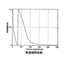
電動パワーステアリングでは、路面情報をドライバに伝える途中に油圧式パワーステアリングにはない電動式モータが存在し、モータの持つ摩擦及び慣性により路面情報のほとんどがブロックされてしまい、ドライバに伝えにくい構成となっている。一方、電動パワーステアリングは、モータの存在により不要外乱を遮断できる利点も持ち合わせている。本発明者は永年電動パワーステアリング装置の研究に携わって来ており、路面からの情報について、必要な情報と外乱として抑圧されるべき情報とで、大よそ図1のように分けられることを知見した。即ち、ドライバが感応する周波数に対する相補感度関数T(s)は常時1以下であり、電動パワーステアリング装置の固有値(10Hz〜13Hz)からサスペンションの固有値(13Hz〜17Hz)を経て、更にフラッタ振動領域(15Hz〜25Hz)を経てモータのトルクリップル領域(15Hz〜30Hz)までの領域において平坦、つまり0dB=1に近い直線特性となっており、他の領域においてゼロに近づくような傾斜特性となっている。
【0014】
ここにおいて、電動パワーステアリング装置では周波数領域上での設計が可能であるため、トレードオフの問題を図30における相補感度関数の周波数領域上で区別して解決することが可能である。つまり、良いステアリングでは不要な外乱は抑圧し、必要な外乱をハンドルに伝えることができる。例えば従来の油圧式パワーステアリングでは、この問題に対してステアリング系の摩擦を調整することで対処しているが、両方を同時に満足させることはできない。これに対し電動パワーステアリングでは、路面からハンドルまでの伝達特性を定義できるので、周波数領域でトレードオフの問題を解決することができる。具体的には、制御系の相補感度関数を抑圧したい外乱が存在する帯域では相補感度関数T(s)が“1”に近づくように、伝えたい外乱が存在する領域では相補感度関数T(s)をゼロに近づけるように設定する。即ち、相補感度関数T(s)の定義から、“1”のときは完全に外乱を抑圧し、ゼロのときは全く抑圧されずに伝わることを意味するからである。
【0015】
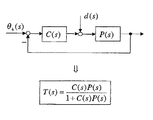
相補感度関数は自動車がSAT(セルフアライニングトルク)を発生するまでの伝達特性を単純なばね(ばね乗数Kv)を持つものとして計算し、常数ゲインはK/Kv/α2となる。また、抑圧したい外乱が存在する帯域では、相補感度関数は1に近くなる。そして、相補感度関数を定義する上で、図30を以下のように解釈する。図30はトーションバーの変位を減少させるように制御を行う制御系という解釈ができ、トーションバーの変位を減らすことは、図30より操舵トルクを減らすことと等価である。従って、θhを目標にθbをフィードバックし、制御ゲインK(トーションバーの剛性)と電動パワーステアリングのコントローラを持つ制御系とみなすことができる。ここで、電動パワーステアリングのコントローラの定常ゲインはアシスト特性の勾配になるので、トルクの小さい領域では定常ゲインはゼロである。トーションバーの剛性とコントローラを合わせて新たなコントローラC(s)とし、ステアリング系をP(s)とすると、図2のような一般的な制御系に単純化できる。そして、相補感度関数T(s)は図2に示す式で表わされ、d(s)はタイヤから入ってくる外乱を示しており、この外乱d(s)は不要外乱及び自動車の特性と単純なばねとの動特性の差を含んでいる。従って、相補感度関数T(s)の目的は単純なばねと実際の動特性との差を適度な帯域で伝え、かつ不要外乱を抑圧することになる。
【0016】
そこで、本発明では、路面情報から操舵トルクまでの伝達特性と、操舵角から操舵トルクまでの伝達特性との違いに着目し、不要外乱に対してはモータの慣性を積極的に利用し、操舵したときに感じるモータの慣性はトルク制御系で補償する。図3のゲイン図に、モータの慣性(高慣性、低慣性)による操舵角から操舵トルクまでの伝達特性の比較を示す。図3に示すモータの周波数応答より、モータの慣性の影響は位相遅れ特性として現れることが明らかであり、モータの慣性の影響は位相遅れ特性の逆特性となる位相進み特性を用いることにより、トルク制御系で補償することができる。図3の位相図の特性Aが補償なしの場合であり、特性Bが補償した場合である。
【0017】
路面感度設計を行うに際し、先ずは路面情報がトルクセンサによって検出できなくてはならない。即ち、モータが路面情報を阻止するのを防ぐような構成をとった上で、トルク制御系の相補感度関数が図1に示す特性に近づくように設計する。タイヤで発生する路面情報は各要素の摩擦分を差し引いた量で伝えられ、モータの慣性は機械的なローパスフィルタとして働くため、慣性が大きいと路面情報が減衰してしまう。相補感度関数の設計は、一般の制御系設計方法等を応用し十分に制御系の安定性を確保した上で、車両に合わせたファインチュ−ニングを行う。というのは、人の感性は微妙であり、理想的な特性を伝達特性で表現できないからであり、保守的になり易い一般の設計方法では十分な対応がなし得ないからである。このため、チューニング自体がチューニング技術者のノウハウに依存しているのが実情である。
【0018】
これに対し、本発明では図1に示す相補感度関数を実現するために、転がり式ラックアンドピニオン、モータ減速機構のラバーダンパ、非接触式トルクセンサ及びトルク制御系を改善している。以下に、これら手法を順次説明する。
【0019】
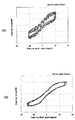
モータが路面情報を阻止するのを防ぐ上で、次の要素(1)〜(3)が有効である。即ち、(1)オブザーバを用いた状態フィードバックによる路面情報に適したモータ特性の定義、(2)メカニカルクラッチ機構採用によるモータとコラム軸のディカップリング、(3)低摩擦要素の採用、である。このようにして設計した電動パワーステアリング装置の特性例を、油圧式の特性と比較して図4乃至図7に示す。図4はチューニングされた路面感度の測定例であり、太線が感度(dB)であり、細線が位相(度)を示している。また、図5及び図6はそれぞれベルジアン路を走行したときの操舵トルクの測定例を油圧式と電動式について示しており、油圧式パワーステアリング装置の操舵トルクが変動しているのはサスペンションの振動を検知しているためである。図5及び図6の各(A)図は時間に対する操舵トルクの変動を示しており、各(B)図は0〜60Hzの周波数応答を示している。図7(A)は100Km/hで走行したときの油圧式パワーステアリング装置の操舵特性(操舵角度対操舵トルク)の測定例であり、図7(B)は100Km/hで走行したときの電動パワーステアリング装置の操舵特性(操舵角度対操舵トルク)の測定例であり、油圧式パワーステアリング装置の操舵トルクが変動しているのはフラッタによる振動を検知しているためである。
【0020】
次に、本発明で使用する転がり式ラックアンドピニオンの機構を図8に示し、その特性を図9に示して従来機構と比較して説明する。即ち、入力軸にはピニオン軸が同軸に装着され、そのピニオン軸がラック軸に噛合されており、ラック軸はローラを介してハウジング内のプレッシャパッド部のピン軸に結合されている。ピン軸はニードル軸受で保持され、摩擦ブロックを経てコイルスプリングに結合されている。コイルスプリングは保持器に収容され、プレッシャパッド部に押圧力を印加するようになっており、保持器はハウジングの内壁との間に懸架されたスプリングによって弾性的に保持されている。なお、かかる転がり式ラックアンドピニオンの詳細は、本出願人による特願平10−335218号に詳述されている。
【0021】
本発明の転がり式ラックアンドピニオンはピニオンを支持しているプレッシャパッド部が、ローラ、摩擦ブロック、ニードル軸受、保持器等で構成されているため、高支持剛性と低作動抵抗を両立できる。特に、図10に示す従来の滑り式ラックアンドピニオンの機構と比較すると、図9の特性図から分るようにプレッシャパッド部に摩擦ブロックが配設されていることにより、ラック推力が低い領域での逆入力が低いことが特徴で、高速走行で重要な微小舵角領域での路面情報改善に役立つ。図10に示す従来の機構(摩擦ブロックなし)では、プレッシャパッド部に摩擦ブロック等がないため、ラック推力が低い領域で逆入力が高くなっている。
【0022】
次に、本発明によるモータ減速ギア部におけるラバーダンパについて説明する。
【0023】
電動パワーステアリング装置では図11に示すように、モータ減速ギアのウォーム軸支持部に、ギアのラトル音の低減のために、ラバーダンパ(ゴム)をブッシュを介してスプライン部に挿入している。一方、ゴムの弾性域では、モータの変位とコラム軸の変位とが独立して作動可能であるため、モータの摩擦及び慣性に阻止されることなく路面情報をハンドル軸に伝えることができる。従って、図1に示すような路面情報の感度関数の設計を、本機構により実現することが可能である。ただし、ラバーダンパの挿入により、制御対象が固有振動数の低い動特性を持つことになるので、制御器の構成が高次になる。
【0024】
ラバーダンパを装着しない場合の周波数特性は図12に示すようになり、ラバーダンパを装着すると図13に示すような周波数特性となり、ノイズレベルが減少することが分る。
【0025】
次に、電動パワーステアリングに使用するトルクセンサの改良について説明する。
【0026】
トルクセンサの検出特性のヒステリシス特性は、微小トルクにおいては遅れ特性として見えてくるため、なるべく小さく抑える必要がある。この目的から、本発明では、図14及び図15に示すようなヒステリシス幅の小さい非接触式トルクセンサを使用する。即ち、図14は非接触式トルクセンサのステアリングホイール軸への配設構造を示しており、図15はセンサ部の構造を一部断面の斜視図で示している。SUS,Fe等の磁性材で成る入力軸(センサシャフト)の外周部には、検出回路ユニットを形成するボビンヨークがスリーブ上に配設されており、ボビンヨーク内には2組のコイルが巻回されている。スリーブは導電性の非磁性材(例えばアルミニウム)で成り、円環状のコイル列に沿って窓が形成されており、入力軸の内部にはトーションバーが配設されている。
【0027】
このような構成において、スリーブの導電性及び非磁性と入力軸の磁性を利用して、入力軸に対するトルクを非接触で検出する。即ち、表皮効果を利用してスリーブ内側に周方向に周期的な磁界の緻密状態を作り出し、その磁界と入力軸のスプラインの位相差によって入力軸の自発磁化を増減させ、それにより生じるインピーダンス変化を、コイル等で形成されたブリッジ回路によりコイル端電圧変化として検出するようになっている。
【0028】
次に、電気制御系の設計について説明する。
【0029】
路面情報の感度設計を実現する上で、電流制御の応答性も重要な要素である。特に電流が流れ始めるあたりの応答性は、中立付近の操舵性を改善する上でできるだけ線形化することが望ましい。線形化に際し、従来のようなPI制御器をベースにした電流制御の代わりに、規範モデルをベースにしたロバスト制御を採用することにより、電流制御の線形化を行っている。
【0030】
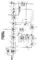
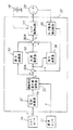
図16は本発明による制御機能のブロック図である。操舵トルクTは操舵補助指令値演算部100及びセンタ応答性改善部101に入力され、各出力が加算器102に入力され、その加算結果がトルク制御演算部103に入力されている。トルク制御演算部103の出力信号はモータロス電流補償部104に入力され、その出力が加算器105を経て最大電流制限部106に入力され、最大電流値が制限されて電流制御部110に入力される。電流制御部110の出力は、Hブリッジ特性補償部111を経て電流ドライブ回路112に入力され、これによりモータ113を駆動する。
【0031】
モータ113のモータ電流iは、モータ電流オフセット補正部120を経てモータ角速度推定部121、電流ドライブ切換部122及び電流制御部110に入力され、モータ端子電圧Vmはモータ角速度推定部121に入力される。モータ角速度推定部121で推定された角速度ωはモータ角加速度推定部・慣性補償部123、モータロストルク補償部124及びヨーレート推定部125に入力され、ヨーレート推定部125の出力は収れん制御部126に入力され、収れん制御部126及びモータロストルク補償部124の各出力は加算器127で加算され、その加算結果が加算器102に入力される。また、電流ディザ信号発生部130が設けられており、電流ディザ信号発生部130及びモータ角加速度推定部・慣性補償部123の各出力が加算器131で加算され、その加算結果が加算器105に入力されている。
【0032】
このような構成において、本発明では先ずセンタ応答性改善部101を図17に示すように、位相補償部101A、近似微分部101B及びゲイン設定部101Cで構成とし、位相補償部101Aを図18に示す周波数特性とし、近似微分部101Bを図19に示す周波数特性とする。これにより、位相補償と近似微分との合成特性は図20に示すようになる。また、ゲイン設定部101Cでは、車速V及び操舵トルクTによってゲインを図21のように切り換えて設定する。更に、ハンドルが急に戻されるような不安な操舵感を低減し、保舵を安定させるため、操舵トルク大で、かつ操舵トルク変化率大とし、操舵トルク減少方向の場合にゲインを小さくする。即ち、切り換え条件は、|操舵トルク|(=A)>約1.37Nm、かつ|操舵トルクー操舵トルク(1サンプリング前)|(=B)>約0.137Nm、かつsign(A)<>sign(B)である。切り換え後のゲインは例えば、車速0〜2で“46”、車速4〜78で“47”、車速80以上で“41”である。なお、sign(A)<>sign(B)は、A=操舵トルクと、B=操舵トルクー操舵トルク(1サンプリング前)の符号が異なることを意味している。
【0033】
また、本発明では操舵補助指令値演算部100におけるアシスト量の計算において、3つの代表車速(0、30、254Km/h)によるアシスト特性を基本特性として設定し、その他の車速では車速補間ゲインに応じて各基本特性間を車速2Km/h毎の補間を行う。そして、アシスト特性の車速設定範囲0〜254Km/h、分解能2Km/hとする。基本アシスト特性(トルク対電流)は図22に示すものであり、0Km/h=lo特性、30Km/h=la特性、254Km/h=lb特性で表わされている。そして、その他の車速についての車速補間演算は、図23で示す車速(Km/h)対車速補間係数γで2Km/h毎に行う。車速0〜30Km/hのとき、アシスト電流IはI=la(T)+γ(V)(lo(T)−la(T))であり、車速32〜254Km/hのとき、アシスト電流IはI=lb(T)+γ(V)(la(T)−lb(T))である。
【0034】
更に、本発明ではトルク制御演算部103として電動パワーステアリング装置の機械系の安定化、減速ギア部ゴムダンパによる振動の安定化、操舵フィーリングの調整のため、操舵トルク応答を設定するようにしている。その構成は図24に示すようになっており、クランプ回路103Aの後段に応答性定義部103Bが設けられ、その後段にクランプ回路103Cを経てロバスト安定化補償部103Dが設置されている。そして、ロバスト安定化補償部103Dの後段にクランプ回路103Eを経て位相補償部103Fが設けられ、更にクランプ回路103Gを経てロバスト安定化補償部103Hが設置されている。
【0035】
ロバスト安定化補償部103Hの特性は図25に示すものであり、制御系全体の特性を図26のようにする。機械系の特性が図27に示すようになっているため、総合的には山部と谷部が相殺されて、ほぼ平坦な特性となる。
【0036】
また、本発明では、モータ電流が流れてもモータ出力に現れない電流を上乗せして、モータ出力トルク0からの立ち上りを改善するため、センタ感のチューニングとして設定する。そのため、補償値はトルク制御演算出力の符号と同じ符号となるように加算し、補償値は車速により4段階に切り換える。
【0037】
【発明の効果】
本発明では路面情報からの望ましい相補感度関数を求め、その相補感度関数に対応して機械系及び電流制御系を設計しているので、不自然な操舵感を防ぐことができ、快適な操舵フィーリングを得ることができる。
【図面の簡単な説明】
【図1】望ましい相補感度関数を示す特性図である。
【図2】図30の単純化ブロック構成図である。
【図3】モータ特性を示す周波数応答図である。
【図4】路面入力から操舵トルクまでの伝達特性のチューニング例を示す図である。
【図5】ベルジアン路を走行したときの操舵トルクの測定例(油圧式)を示す図である。
【図6】ベルジアン路を走行したときの操舵トルクの測定例(電動式)を示す図である。
【図7】100Km/hで走行したときの操舵特性例を示す図である。
【図8】本発明で使用する転がり式ラックアンドピニオンの機構図である。
【図9】図7の機構の特性例を従来装置と比較して示す図である。
【図10】従来の転がり式ラックアンドピニオンの機構図である
【図11】モータ減速ギアのウォーム軸支持部の機構図である。
【図12】ウォーム軸支持部にゴムを装着しない場合の特性を示す図である。
【図13】ウォーム軸支持部にゴムを装着した場合の特性を示す図である。
【図14】本発明で使用するトルクセンサの断面機構図である。
【図15】本発明で使用するトルクセンサの斜視図である。
【図16】本発明の電動パワーステアリング装置の構成例を示すブロック図である。
【図17】センタ応答改善部のブロック構成図である。
【図18】位相補償部の特性例を示す図である。
【図19】近似微分部の特性例を示す図である。
【図20】位相補償部及び近似微分部の合成特性を示す図である。
【図21】車速及び操舵トルクによるゲインの設定例を示す図である。
【図22】基本アシスト特性を示す図である。
【図23】車速補間演算の一例を示す図である。
【図24】トルク制御演算の構成例を示すブロック図である。
【図25】ロバスト安定化補償の特性例を示す図である。
【図26】制御系の特性例を示す図である。
【図27】機械系の特性例を示す図である。
【図28】電動パワーステアリングの一般例を示す機構図である。
【図29】コントロールユニットの一般的な内部構成を示すブロック図である。
【図30】その伝達関数を示すブロック線図である。
【符号の説明】
10 トルクセンサ
12 車速センサ
20 モータ
30 コントロールユニット
100 操舵補助指令値演算部
101 センタ応答性改善部
103 トルク制御演算部
110 電流制御部
112 電流ドライブ回路
113 モータ
121 モータ角速度推定部
124 モータロストルク補償部
125 ヨーレート推定部
126 収れん制御部[0001]
BACKGROUND OF THE INVENTION
The present invention relates to a control device for an electric power steering apparatus in which a steering assist force by a motor is applied to a steering system of an automobile or a vehicle, and a particularly desirable complementary sensitivity function is obtained, and the mechanical system and control are matched to the complementary sensitivity function. The present invention relates to a control device for an electric power steering apparatus for which a system is designed.
[0002]
[Prior art]
An electric power steering device for energizing an automobile or vehicle steering device with an auxiliary load by the rotational force of a motor is an auxiliary load applied to a steering shaft or a rack shaft by a transmission mechanism such as a gear or a belt via a speed reducer. It comes to be energized. Such a conventional electric power steering apparatus performs feedback control of motor current in order to accurately generate assist torque (steering assist torque). The feedback control adjusts the motor applied voltage so that the difference between the current control value and the motor current detection value becomes small. The adjustment of the motor applied voltage is generally performed by a PWM (pulse width modulation) control duty. This is done by adjusting the tee ratio.
[0003]
About 10 years have passed since the introduction of electric power steering devices on the market, and the applicable models have been expanded to the 2000cc class. At the same time, the performance required for the steering device has been advanced. Recently, we have not only caught up with the performance of conventional hydraulic power steering, but also developed functions that take advantage of the characteristics of electric power steering, aiming at the emergence of new value-added products.
[0004]
Here, the general configuration of the electric power steering apparatus will be described with reference to FIG. 28. The shaft of the steering wheel is coupled to the tie rod of the traveling wheel via a torsion bar, a reduction gear, a universal joint, and the like. The steering wheel shaft is provided with a torque sensor for detecting the steering torque of the steering wheel. A motor for assisting the steering force of the steering wheel is coupled to the shaft via a clutch (not shown) and a reduction gear. Yes. A control unit (ECU) that controls the power steering device is supplied with electric power from a battery via an ignition key (not shown), and the control unit detects the steering torque T detected by the torque sensor and a vehicle speed sensor (not shown). The steering assist command value I of the assist command is calculated based on the vehicle speed V detected in step), and the current supplied to the motor is controlled based on the calculated steering assist command value I. In FIG. 28, SAT represents self-aligning torque.
[0005]
Although the control unit is mainly composed of a CPU, a general function executed by a program in the CPU is shown in FIG.
[0006]
The function and operation of the
[0007]
A block diagram based on the transfer function of such an electric power steering apparatus is shown in FIG. 30, and “s” represents a Laplace operator.
[0008]
[Problems to be solved by the invention]
In particular, the electric power steering has an advantage that information from the road surface can be processed and transmitted so that the driver can easily drive using the degree of freedom of design. From FIG. 28 and FIG. 30, it can be seen that the sensitivity design for road surface information can be treated as a problem of how to define the transfer characteristic from the input from the road surface to the steering torque as a desirable characteristic.
[0009]
On the other hand, in order to realize a steering feeling desirable for the driver, it is realized by tuning a transmission characteristic from the steering angle to the steering torque. In general, a demand for a clean steering feeling or a moist steering feeling greatly depends on this transmission characteristic. Here, it can be seen from the schematic block diagram of FIG. 30 that the two specifications are in a trade-off relationship. Specifically, this corresponds to an example in which the steering feels a friction as a result of applying friction to the power steering system in order to reduce the sensitivity to flutter generated at high speeds.
[0010]
In the field of electric power steering devices, it is a function that takes advantage of the features of electric power steering and surpasses hydraulic power steering performance, and it is suitable for the desired complementary sensitivity function that matches the road surface information and the electric control system and electric control The present invention, which requires the appearance of a device designed to obtain a stable and comfortable steering feeling, has been made under the circumstances described above, and an object of the present invention is to provide a desirable complementary sensitivity function. An object of the present invention is to provide a control device for an electric power steering device in which a control system is designed in accordance with the complementary sensitivity function.
[0011]
[Means for Solving the Problems]
The present invention controls the motor that applies a steering assist force to a steering mechanism based on a current control value calculated from a steering assist command value calculated based on a steering torque generated in a steering shaft and a current value of the motor. The above-mentioned object of the present invention is to make the complementary sensitivity function with respect to the
[0012]
Further, by setting the frequency band of the disturbance to be suppressed to 10 to 30 Hz , or the natural value of the power steering device is 10 to 13 Hz, the natural value of the suspension is 13 to 17 Hz, the flutter vibration region is 15 to 25 Hz, and the motor by the torque ripple area and 15~30Hz, or the complementary sensitivity function so as to obtain from the design of a machine control system and electric control system, the machine control system of the rolling rack and pinion mechanism, the motor speed-reduction mechanism By obtaining from the mechanical design of the rubber damper and the non-contact torque sensor, the above object of the present invention can be achieved more effectively.
[0013]
DETAILED DESCRIPTION OF THE INVENTION
In electric power steering, there is an electric motor that is not in hydraulic power steering in the middle of transmitting road surface information to the driver, and most of the road surface information is blocked by the friction and inertia of the motor, and it is difficult to transmit to the driver It has become. On the other hand, the electric power steering has an advantage that unnecessary disturbance can be blocked by the presence of the motor. The present inventor has been engaged in research on electric power steering devices for many years, and it has been found that the information from the road surface can be roughly divided into necessary information and information to be suppressed as disturbance as shown in FIG. did. That is, the complementary sensitivity function T (s) with respect to the frequency to which the driver is sensitive is always 1 or less, and passes through the eigenvalue (10 Hz to 13 Hz) of the electric power steering apparatus to the eigenvalue (13 Hz to 17 Hz) of the suspension, and further to the flutter vibration region ( 15 Hz to 25 Hz), the torque ripple region (15 Hz to 30 Hz) of the motor is flat in the region, that is, linear characteristics close to 0 dB = 1, and in other regions, the inclination characteristics approach zero. .
[0014]
Here, since the electric power steering apparatus can be designed in the frequency domain, the trade-off problem can be distinguished and solved in the frequency domain of the complementary sensitivity function in FIG. That is, unnecessary disturbance can be suppressed with good steering, and the necessary disturbance can be transmitted to the steering wheel. For example, in conventional hydraulic power steering, this problem is dealt with by adjusting the friction of the steering system, but both cannot be satisfied at the same time. On the other hand, in the electric power steering, since the transfer characteristic from the road surface to the steering wheel can be defined, the trade-off problem can be solved in the frequency domain. Specifically, the complementary sensitivity function T (s) in the region where the disturbance to be transmitted exists so that the complementary sensitivity function T (s) approaches “1” in the band where the disturbance in which the complementary sensitivity function of the control system is to be suppressed exists. ) To be close to zero. That is, from the definition of the complementary sensitivity function T (s), “1” means that the disturbance is completely suppressed, and “0” means that it is transmitted without being suppressed at all.
[0015]
Complementary sensitivity function automobiles is calculated as having SAT simple spring the transfer characteristic up to generate a (self-aligning torque) (spring multiplier Kv), constant gain becomes K / Kv / α 2. Further, the complementary sensitivity function is close to 1 in a band where there is a disturbance to be suppressed. Then, in defining the complementary sensitivity function, FIG. 30 is interpreted as follows. FIG. 30 can be interpreted as a control system that performs control so as to reduce the displacement of the torsion bar, and reducing the displacement of the torsion bar is equivalent to reducing the steering torque from FIG. Therefore, θ b is fed back with θ h as a target, and can be regarded as a control system having a control gain K (rigidity of torsion bar) and an electric power steering controller. Here, since the steady gain of the controller of the electric power steering has a gradient of the assist characteristic, the steady gain is zero in a region where the torque is small. If the rigidity of the torsion bar and the controller are combined to form a new controller C (s) and the steering system is P (s), the general control system as shown in FIG. 2 can be simplified. The complementary sensitivity function T (s) is expressed by the equation shown in FIG. 2, and d (s) indicates a disturbance coming from the tire. The disturbance d (s) is an unnecessary disturbance and the characteristics of the vehicle. It includes a difference in dynamic characteristics from a simple spring. Therefore, the purpose of the complementary sensitivity function T (s) is to transmit the difference between a simple spring and actual dynamic characteristics in an appropriate band, and to suppress unnecessary disturbances.
[0016]
Therefore, in the present invention, paying attention to the difference between the transmission characteristic from the road surface information to the steering torque and the transmission characteristic from the steering angle to the steering torque, the inertia of the motor is actively used for unnecessary disturbance, and the steering is The torque control system compensates for the motor inertia. The gain diagram of FIG. 3 shows a comparison of transmission characteristics from the steering angle to the steering torque due to the motor inertia (high inertia, low inertia). It is clear from the frequency response of the motor shown in FIG. 3 that the influence of the motor inertia appears as a phase lag characteristic, and the influence of the motor inertia is obtained by using a phase advance characteristic that is the reverse of the phase lag characteristic. It can be compensated by the control system. This is a case where the characteristic A in the phase diagram of FIG. 3 is uncompensated and a characteristic B is compensated.
[0017]
When designing road surface sensitivity, first, road surface information must be detectable by a torque sensor. That is, after taking a configuration that prevents the motor from blocking road surface information, the torque control system is designed so that the complementary sensitivity function approaches the characteristics shown in FIG. The road surface information generated by the tire is transmitted in an amount obtained by subtracting the friction of each element, and the inertia of the motor works as a mechanical low-pass filter. Therefore, if the inertia is large, the road surface information is attenuated. In designing the complementary sensitivity function, a general control system design method or the like is applied to sufficiently secure the stability of the control system, and then fine tuning according to the vehicle is performed. This is because human sensitivity is delicate and ideal characteristics cannot be expressed by transfer characteristics, and a general design method that tends to be conservative cannot provide sufficient response. Therefore, the actual situation is that the tuning itself depends on the know-how of the tuning engineer.
[0018]
In contrast, the present invention improves the rolling rack and pinion, the rubber damper of the motor speed reduction mechanism, the non-contact torque sensor, and the torque control system in order to realize the complementary sensitivity function shown in FIG. Hereinafter, these methods will be described in order.
[0019]
The following elements (1) to (3) are effective in preventing the motor from blocking the road surface information. That is, (1) Definition of motor characteristics suitable for road surface information by state feedback using an observer, (2) Decoupling of motor and column shaft by employing a mechanical clutch mechanism, and (3) Employing a low friction element. . Examples of the characteristics of the electric power steering apparatus designed in this way are shown in FIGS. 4 to 7 in comparison with hydraulic characteristics. FIG. 4 is a measurement example of the tuned road surface sensitivity, where a thick line indicates sensitivity (dB) and a thin line indicates phase (degree). FIGS. 5 and 6 show examples of measurement of the steering torque when traveling on a Belgian road, both for the hydraulic type and the electric type. The steering torque of the hydraulic power steering device fluctuates because of vibration of the suspension. This is because it is detected. Each of FIG. 5 and FIG. 6A shows the fluctuation of the steering torque with respect to time, and each FIG. 5B shows the frequency response of 0 to 60 Hz. FIG. 7A is a measurement example of the steering characteristics (steering angle versus steering torque) of the hydraulic power steering apparatus when traveling at 100 km / h, and FIG. 7B is an electric diagram when traveling at 100 km / h. This is a measurement example of the steering characteristics (steering angle versus steering torque) of the power steering device, and the steering torque of the hydraulic power steering device fluctuates because vibration due to flutter is detected.
[0020]
Next, the mechanism of the rolling rack and pinion used in the present invention is shown in FIG. 8, and its characteristics are shown in FIG. That is, a pinion shaft is coaxially mounted on the input shaft, and the pinion shaft is meshed with the rack shaft, and the rack shaft is coupled to the pin shaft of the pressure pad portion in the housing via a roller. The pin shaft is held by a needle bearing and is coupled to a coil spring via a friction block. The coil spring is housed in a cage and applies a pressing force to the pressure pad portion, and the cage is elastically held by a spring suspended between the inner wall of the housing. The details of the rolling rack and pinion are described in Japanese Patent Application No. 10-335218 by the present applicant.
[0021]
In the rolling rack and pinion of the present invention, the pressure pad portion supporting the pinion is composed of a roller, a friction block, a needle bearing, a cage, and the like, so that both high support rigidity and low operating resistance can be achieved. In particular, as compared with the conventional sliding rack and pinion mechanism shown in FIG. 10, the friction pad is disposed on the pressure pad portion as shown in the characteristic diagram of FIG. This is useful for improving road surface information in a small rudder angle region, which is important for high-speed driving. In the conventional mechanism (without the friction block) shown in FIG. 10, since the pressure pad portion has no friction block or the like, the reverse input is high in the region where the rack thrust is low.
[0022]
Next, the rubber damper in the motor reduction gear part by this invention is demonstrated.
[0023]
In the electric power steering apparatus, as shown in FIG. 11, a rubber damper (rubber) is inserted into the spline portion via a bush in the worm shaft support portion of the motor reduction gear in order to reduce the rattle noise of the gear. On the other hand, in the elastic region of rubber, since the displacement of the motor and the displacement of the column shaft can be operated independently, road surface information can be transmitted to the handle shaft without being blocked by the friction and inertia of the motor. Accordingly, the design of the sensitivity function of the road surface information as shown in FIG. 1 can be realized by this mechanism. However, the insertion of the rubber damper causes the controlled object to have a dynamic characteristic with a low natural frequency, so that the configuration of the controller becomes higher.
[0024]
When the rubber damper is not attached, the frequency characteristic is as shown in FIG. 12, and when the rubber damper is attached, the frequency characteristic is as shown in FIG. 13, and the noise level is reduced.
[0025]
Next, an improvement of a torque sensor used for electric power steering will be described.
[0026]
Since the hysteresis characteristic of the detection characteristic of the torque sensor appears as a delay characteristic in a minute torque, it is necessary to keep it as small as possible. For this purpose, the present invention uses a non-contact torque sensor with a small hysteresis width as shown in FIGS. That is, FIG. 14 shows the arrangement structure of the non-contact torque sensor on the steering wheel shaft, and FIG. 15 shows the structure of the sensor part in a partially sectional perspective view. SUS, the outer periphery of the input shaft made of a magnetic material such as Fe (sensor shaft), and Bobin'yoku forming the detecting circuit unit is disposed on the sleeve, two sets of coils wound around in the Bobin'yoku ing. The sleeve is made of a conductive non-magnetic material (for example, aluminum), has a window formed along an annular coil array, and a torsion bar is disposed inside the input shaft.
[0027]
In such a configuration, the torque with respect to the input shaft is detected in a non-contact manner by utilizing the conductivity and non-magnetism of the sleeve and the magnetism of the input shaft. In other words, the skin effect is used to create a dense state of a periodic magnetic field in the circumferential direction inside the sleeve, the spontaneous magnetization of the input shaft is increased or decreased by the phase difference between the magnetic field and the spline of the input shaft, and the impedance change caused thereby is changed. The change in the coil end voltage is detected by a bridge circuit formed of a coil or the like.
[0028]
Next, the design of the electric control system will be described.
[0029]
Responsiveness of current control is an important factor in realizing the sensitivity design of road surface information. In particular, it is desirable to linearize the responsiveness when the current starts to flow as much as possible in order to improve the steering performance near the neutral position. In the linearization, the current control is linearized by adopting the robust control based on the reference model instead of the current control based on the conventional PI controller.
[0030]
FIG. 16 is a block diagram of the control function according to the present invention. The steering torque T is input to the steering assist command
[0031]
The motor current i of the
[0032]
In such a configuration, in the present invention, as shown in FIG. 17, the center
[0033]
In the present invention, the assist characteristic based on the three representative vehicle speeds (0, 30, 254 Km / h) is set as a basic characteristic in the calculation of the assist amount in the steering assist command
[0034]
Further, in the present invention, as the torque
[0035]
Characteristics of the robust stabilizing compensation section 103H are those shown in FIG. 25, the characteristics of the entire control system so that in Figure 2 6. Since the characteristics of the mechanical system are as shown in FIG. 27, the peak portion and the valley portion are canceled out as a whole, resulting in a substantially flat characteristic.
[0036]
Further, in the present invention, in order to improve the rise from the
[0037]
【The invention's effect】
In the present invention, a desirable complementary sensitivity function is obtained from road surface information, and the mechanical system and the current control system are designed in accordance with the complementary sensitivity function, so that an unnatural steering feeling can be prevented and a comfortable steering fee can be prevented. You can get a ring.
[Brief description of the drawings]
FIG. 1 is a characteristic diagram showing a desirable complementary sensitivity function.
FIG. 2 is a simplified block configuration diagram of FIG. 30;
FIG. 3 is a frequency response diagram showing motor characteristics.
FIG. 4 is a diagram illustrating a tuning example of transfer characteristics from road surface input to steering torque.
FIG. 5 is a diagram showing a measurement example (hydraulic type) of steering torque when traveling on a Belgian road;
FIG. 6 is a diagram showing a measurement example (electric type) of steering torque when traveling on a Belgian road.
FIG. 7 is a diagram showing an example of steering characteristics when traveling at 100 km / h.
FIG. 8 is a mechanism diagram of a rolling rack and pinion used in the present invention.
FIG. 9 is a diagram showing a characteristic example of the mechanism of FIG. 7 in comparison with a conventional device.
10 is a mechanism diagram of a conventional rolling rack and pinion. FIG. 11 is a mechanism diagram of a worm shaft support portion of a motor reduction gear.
FIG. 12 is a diagram showing characteristics when rubber is not attached to the worm shaft support portion.
FIG. 13 is a diagram showing characteristics when rubber is attached to a worm shaft support portion.
FIG. 14 is a sectional mechanism diagram of a torque sensor used in the present invention.
FIG. 15 is a perspective view of a torque sensor used in the present invention.
FIG. 16 is a block diagram illustrating a configuration example of an electric power steering apparatus according to the present invention.
FIG. 17 is a block diagram of a center response improving unit.
FIG. 18 is a diagram illustrating a characteristic example of a phase compensation unit.
FIG. 19 is a diagram illustrating an example of characteristics of an approximate differentiation unit.
FIG. 20 is a diagram illustrating a combined characteristic of a phase compensation unit and an approximate differentiation unit.
FIG. 21 is a diagram illustrating an example of setting gains based on vehicle speed and steering torque.
FIG. 22 is a diagram showing basic assist characteristics.
FIG. 23 is a diagram illustrating an example of vehicle speed interpolation calculation.
FIG. 24 is a block diagram illustrating a configuration example of torque control calculation.
FIG. 25 is a diagram illustrating a characteristic example of robust stabilization compensation;
FIG. 26 is a diagram illustrating a characteristic example of a control system.
FIG. 27 is a diagram illustrating an example of characteristics of a mechanical system.
FIG. 28 is a mechanism diagram showing a general example of electric power steering.
FIG. 29 is a block diagram showing a general internal configuration of a control unit.
FIG. 30 is a block diagram showing the transfer function.
[Explanation of symbols]
DESCRIPTION OF
Claims (4)
前記抑圧したい外乱が存在する帯域に、パワーステアリング装置の固有値、サスペンションの固有値、フラッタ振動領域及びモータのトルクリップル領域が含まれていることを特徴とする電動パワーステアリング装置の制御装置。The motor that provides steering assist force to the steering mechanism is controlled based on a current control value calculated from the steering assist command value calculated by the calculation means based on the steering torque generated in the steering shaft and the current value of the motor. In the control device for the electric power steering device, the complementary sensitivity function for the frequency is set so that it approaches 1 in the band where the disturbance to be suppressed exists, and close to zero in the band where the disturbance to be transmitted exists ,
A control device for an electric power steering apparatus, wherein a band in which a disturbance to be suppressed exists includes an eigenvalue of a power steering apparatus, an eigenvalue of a suspension, a flutter vibration area, and a torque ripple area of a motor.
Priority Applications (5)
| Application Number | Priority Date | Filing Date | Title |
|---|---|---|---|
| JP2000154284A JP3780823B2 (en) | 2000-05-25 | 2000-05-25 | Control device for electric power steering device |
| DE10192088T DE10192088B4 (en) | 2000-05-25 | 2001-05-14 | Control unit for an electric power steering |
| GB0201821A GB2367543B (en) | 2000-05-25 | 2001-05-14 | Control unit for electric power steering apparatus |
| PCT/JP2001/003982 WO2001089911A1 (en) | 2000-05-25 | 2001-05-14 | Controller for motor power steering system |
| US10/048,010 US6751538B2 (en) | 2000-05-25 | 2001-05-14 | Controller for motor power steering system |
Applications Claiming Priority (1)
| Application Number | Priority Date | Filing Date | Title |
|---|---|---|---|
| JP2000154284A JP3780823B2 (en) | 2000-05-25 | 2000-05-25 | Control device for electric power steering device |
Related Child Applications (1)
| Application Number | Title | Priority Date | Filing Date |
|---|---|---|---|
| JP2006013488A Division JP2006143210A (en) | 2006-01-23 | 2006-01-23 | Control device for electric power steering device |
Publications (3)
| Publication Number | Publication Date |
|---|---|
| JP2001334948A JP2001334948A (en) | 2001-12-04 |
| JP2001334948A5 JP2001334948A5 (en) | 2004-09-09 |
| JP3780823B2 true JP3780823B2 (en) | 2006-05-31 |
Family
ID=18659406
Family Applications (1)
| Application Number | Title | Priority Date | Filing Date |
|---|---|---|---|
| JP2000154284A Expired - Fee Related JP3780823B2 (en) | 2000-05-25 | 2000-05-25 | Control device for electric power steering device |
Country Status (5)
| Country | Link |
|---|---|
| US (1) | US6751538B2 (en) |
| JP (1) | JP3780823B2 (en) |
| DE (1) | DE10192088B4 (en) |
| GB (1) | GB2367543B (en) |
| WO (1) | WO2001089911A1 (en) |
Families Citing this family (36)
| Publication number | Priority date | Publication date | Assignee | Title |
|---|---|---|---|---|
| GB2370023B (en) * | 2000-07-21 | 2004-03-10 | Nsk Ltd | Electrically driven power steering apparatus |
| US7219761B2 (en) * | 2000-07-21 | 2007-05-22 | Nsk Ltd. | Motor-operated power steering apparatus |
| JP3899797B2 (en) * | 2000-09-25 | 2007-03-28 | 日本精工株式会社 | Control device for electric power steering device |
| JP4581299B2 (en) * | 2001-06-28 | 2010-11-17 | 日本精工株式会社 | Control device for electric power steering device |
| JP3947014B2 (en) * | 2002-01-25 | 2007-07-18 | 株式会社ジェイテクト | Electric power steering device |
| WO2004026665A1 (en) | 2002-09-19 | 2004-04-01 | Nsk Ltd. | Control device for motorized power steering device |
| FR2851541B1 (en) * | 2003-02-20 | 2006-01-27 | Soc Mecanique Irigny | METHOD FOR MANAGING THE THERMAL PROTECTION OF THE MOTOR OF AN ELECTRIC POWER STEERING OF A MOTOR VEHICLE |
| JP4617716B2 (en) | 2004-05-11 | 2011-01-26 | 株式会社ジェイテクト | Electric power steering device |
| EP1616774A3 (en) * | 2004-07-15 | 2007-08-08 | NSK Ltd., | Electric power steering apparatus |
| JP4349309B2 (en) * | 2004-09-27 | 2009-10-21 | 日産自動車株式会社 | Vehicle steering control device |
| DE102004051338A1 (en) * | 2004-10-21 | 2006-04-27 | Bayerische Motoren Werke Ag | Device for reducing steering wheel torsional vibrations on a motor vehicle and operating method therefor |
| JP4573038B2 (en) * | 2005-04-18 | 2010-11-04 | 株式会社ジェイテクト | Electric power steering device |
| JP4847060B2 (en) | 2005-07-15 | 2011-12-28 | 日立オートモティブシステムズ株式会社 | AC motor drive device and control method thereof |
| EP1864886A2 (en) * | 2006-06-07 | 2007-12-12 | NSK Ltd. | Electric power steering apparatus |
| JP4468415B2 (en) | 2007-06-29 | 2010-05-26 | 三菱電機株式会社 | Electric power steering control device |
| DE102007040912A1 (en) * | 2007-08-30 | 2009-03-05 | Bayerische Motoren Werke Aktiengesellschaft | Sensor-signal characteristic processing method for motor vehicle, involves eliminating interference portion from signal characteristic, and processing usage portion remained after elimination in chassis frame-regulation system |
| JP4329859B2 (en) * | 2007-12-12 | 2009-09-09 | トヨタ自動車株式会社 | Steering control device |
| JP2009166715A (en) * | 2008-01-17 | 2009-07-30 | Nsk Ltd | Electric power steering device |
| JP5158421B2 (en) * | 2008-02-12 | 2013-03-06 | 株式会社ジェイテクト | Vehicle steering system |
| JP5348963B2 (en) * | 2008-08-08 | 2013-11-20 | 株式会社豊田中央研究所 | Steering device |
| JP5433007B2 (en) * | 2008-09-30 | 2014-03-05 | 日産自動車株式会社 | System equipped with support control device for system operator support, control operation support device, control operation support method, driving operation support device, and driving operation support method |
| JP5282889B2 (en) * | 2009-01-13 | 2013-09-04 | トヨタ自動車株式会社 | Vehicle steering control device |
| US8150582B2 (en) * | 2009-04-20 | 2012-04-03 | Ford Global Technologies, Llc | Systems and methods for decoupling steering rack force disturbances in electric steering |
| US8554417B2 (en) * | 2009-06-17 | 2013-10-08 | Honda Motor Co., Ltd. | Narrow-frequency-band feedback control of steering pinion torque in an electric power steering system |
| PL2402234T3 (en) * | 2010-07-01 | 2014-04-30 | Steering Solutions Ip Holding | Dynamic system compensator for actively controlled power steering systems |
| JP5962312B2 (en) * | 2012-08-03 | 2016-08-03 | 株式会社デンソー | Electric power steering control device |
| JP5962586B2 (en) * | 2013-05-24 | 2016-08-03 | 株式会社デンソー | Steering control device |
| JP6138881B2 (en) * | 2015-09-25 | 2017-05-31 | 株式会社Subaru | Steering support control device |
| CN108778899A (en) * | 2016-03-08 | 2018-11-09 | 日本精工株式会社 | The regulating device of electric power-assisted steering apparatus |
| WO2018185528A1 (en) | 2017-04-06 | 2018-10-11 | Kongsberg Inc. | Power steering system and a method of operating same |
| US10464595B2 (en) * | 2017-07-12 | 2019-11-05 | GM Global Technology Operations LLC | System and method for controlling an electric power steering motor |
| SE541786C2 (en) * | 2017-08-28 | 2019-12-17 | Scania Cv Ab | A method for providing vehicle steering support by differential wheel braking, a system, a vehicle, a computer program and a computer-readable medium. |
| KR102298976B1 (en) * | 2017-09-08 | 2021-09-06 | 현대자동차주식회사 | Method for determining assist torque of power steering system |
| US11511795B2 (en) * | 2018-10-11 | 2022-11-29 | Steering Solutions Ip Holding Corporation | Dither noise management in electric power steering systems |
| DE112020003778T5 (en) * | 2019-08-09 | 2022-06-30 | Nidec Corporation | CONTROL DEVICE, DRIVE DEVICE, ELECTRIC POWER STEERING DEVICE AND CONTROL METHOD |
| JP7452243B2 (en) * | 2020-05-22 | 2024-03-19 | 株式会社ジェイテクト | steering system |
Family Cites Families (13)
| Publication number | Priority date | Publication date | Assignee | Title |
|---|---|---|---|---|
| JPS5951150A (en) * | 1982-09-16 | 1984-03-24 | Nissan Motor Co Ltd | Control of idle revolution speed of internal-combustion engine |
| JPS60159433A (en) * | 1984-01-31 | 1985-08-20 | Atsugi Motor Parts Co Ltd | Hydraulic damper |
| US5257828A (en) * | 1992-06-03 | 1993-11-02 | Trw Inc. | Method and apparatus for controlling damping in an electric assist steering system for vehicle yaw rate control |
| JPH06113578A (en) * | 1992-09-30 | 1994-04-22 | Fuji Electric Co Ltd | Motor speed control method |
| JP3372975B2 (en) * | 1992-11-30 | 2003-02-04 | 倉敷化工株式会社 | Active vibration isolation method and vibration isolation device |
| JP3133914B2 (en) * | 1994-12-21 | 2001-02-13 | 三菱電機株式会社 | Electric power steering device |
| JP3493806B2 (en) * | 1995-04-21 | 2004-02-03 | 日本精工株式会社 | Control device for electric power steering device |
| JP3521547B2 (en) * | 1995-05-15 | 2004-04-19 | 日本精工株式会社 | Control device for electric power steering device |
| JPH0922303A (en) * | 1995-07-07 | 1997-01-21 | Komatsu Ltd | Vibration suppressing device |
| US6013994A (en) * | 1996-10-01 | 2000-01-11 | Nsk Ltd. | Controller of electric power-steering system |
| JP3740852B2 (en) * | 1998-08-03 | 2006-02-01 | 日本精工株式会社 | Control device for electric power steering device |
| JP3298006B2 (en) * | 1998-12-24 | 2002-07-02 | 日本精工株式会社 | Control device for electric power steering device |
| WO2001020766A1 (en) * | 1999-09-16 | 2001-03-22 | Delphi Technologies, Inc. | Minimization of motor torque ripple due to unbalanced conditions |
-
2000
- 2000-05-25 JP JP2000154284A patent/JP3780823B2/en not_active Expired - Fee Related
-
2001
- 2001-05-14 US US10/048,010 patent/US6751538B2/en not_active Expired - Lifetime
- 2001-05-14 WO PCT/JP2001/003982 patent/WO2001089911A1/en active Application Filing
- 2001-05-14 DE DE10192088T patent/DE10192088B4/en not_active Expired - Lifetime
- 2001-05-14 GB GB0201821A patent/GB2367543B/en not_active Expired - Fee Related
Also Published As
| Publication number | Publication date |
|---|---|
| DE10192088T1 (en) | 2003-04-03 |
| US20030120404A1 (en) | 2003-06-26 |
| GB2367543A (en) | 2002-04-10 |
| JP2001334948A (en) | 2001-12-04 |
| DE10192088B4 (en) | 2006-03-02 |
| GB2367543B (en) | 2003-08-27 |
| WO2001089911A1 (en) | 2001-11-29 |
| US6751538B2 (en) | 2004-06-15 |
| GB0201821D0 (en) | 2002-03-13 |
Similar Documents
| Publication | Publication Date | Title |
|---|---|---|
| JP3780823B2 (en) | Control device for electric power steering device | |
| JP3899797B2 (en) | Control device for electric power steering device | |
| US6570352B2 (en) | Control unit for electric power steering apparatus | |
| US8340867B2 (en) | Steering system | |
| JP5575919B2 (en) | Electric power steering device | |
| US5845222A (en) | Vehicle steering control system | |
| US5698956A (en) | Control system for electrically operated power steering apparatus | |
| JP4715212B2 (en) | Control device for electric power steering device | |
| JP4660883B2 (en) | Control device for electric power steering device | |
| US6308122B1 (en) | Steering system for motor vehicle | |
| US8798862B2 (en) | Electric power steering device | |
| US20010002631A1 (en) | Electric power steering system | |
| US6744232B2 (en) | Control unit for electric power steering apparatus | |
| KR101606318B1 (en) | Electric power steering apparatus and controlling method thereof | |
| US20100228441A1 (en) | Electric power steering system designed to generate torque for assisting driver's turning effort | |
| JP3777961B2 (en) | Control device for electric power steering device | |
| JP2009051278A (en) | Controller of electric power steering device | |
| JP4088678B2 (en) | Electric power steering device | |
| JP2005324737A (en) | Traveling condition control device for vehicle | |
| JP2006143210A (en) | Control device for electric power steering device | |
| JP3922010B2 (en) | Control device for electric power steering device | |
| JP5028888B2 (en) | Control device for electric power steering device | |
| JP2009166715A (en) | Electric power steering device | |
| JP6252062B2 (en) | Steering control device | |
| JP4449399B2 (en) | Vehicle steering system |
Legal Events
| Date | Code | Title | Description |
|---|---|---|---|
| A131 | Notification of reasons for refusal |
Free format text: JAPANESE INTERMEDIATE CODE: A131 Effective date: 20051122 |
|
| A521 | Written amendment |
Free format text: JAPANESE INTERMEDIATE CODE: A523 Effective date: 20060123 |
|
| TRDD | Decision of grant or rejection written | ||
| A01 | Written decision to grant a patent or to grant a registration (utility model) |
Free format text: JAPANESE INTERMEDIATE CODE: A01 Effective date: 20060214 |
|
| A61 | First payment of annual fees (during grant procedure) |
Free format text: JAPANESE INTERMEDIATE CODE: A61 Effective date: 20060227 |
|
| R150 | Certificate of patent or registration of utility model |
Ref document number: 3780823 Country of ref document: JP Free format text: JAPANESE INTERMEDIATE CODE: R150 Free format text: JAPANESE INTERMEDIATE CODE: R150 |
|
| FPAY | Renewal fee payment (event date is renewal date of database) |
Free format text: PAYMENT UNTIL: 20100317 Year of fee payment: 4 |
|
| FPAY | Renewal fee payment (event date is renewal date of database) |
Free format text: PAYMENT UNTIL: 20100317 Year of fee payment: 4 |
|
| FPAY | Renewal fee payment (event date is renewal date of database) |
Free format text: PAYMENT UNTIL: 20110317 Year of fee payment: 5 |
|
| FPAY | Renewal fee payment (event date is renewal date of database) |
Free format text: PAYMENT UNTIL: 20120317 Year of fee payment: 6 |
|
| FPAY | Renewal fee payment (event date is renewal date of database) |
Free format text: PAYMENT UNTIL: 20130317 Year of fee payment: 7 |
|
| FPAY | Renewal fee payment (event date is renewal date of database) |
Free format text: PAYMENT UNTIL: 20130317 Year of fee payment: 7 |
|
| FPAY | Renewal fee payment (event date is renewal date of database) |
Free format text: PAYMENT UNTIL: 20140317 Year of fee payment: 8 |
|
| R250 | Receipt of annual fees |
Free format text: JAPANESE INTERMEDIATE CODE: R250 |
|
| LAPS | Cancellation because of no payment of annual fees |