JP3777399B2 - Driving force transmission device - Google Patents
Driving force transmission device Download PDFInfo
- Publication number
- JP3777399B2 JP3777399B2 JP2000254426A JP2000254426A JP3777399B2 JP 3777399 B2 JP3777399 B2 JP 3777399B2 JP 2000254426 A JP2000254426 A JP 2000254426A JP 2000254426 A JP2000254426 A JP 2000254426A JP 3777399 B2 JP3777399 B2 JP 3777399B2
- Authority
- JP
- Japan
- Prior art keywords
- magnetic circuit
- driving force
- transmission device
- force transmission
- front housing
- Prior art date
- Legal status (The legal status is an assumption and is not a legal conclusion. Google has not performed a legal analysis and makes no representation as to the accuracy of the status listed.)
- Expired - Lifetime
Links
Images


Description
【0001】
【発明の属する技術分野】
本発明は、駆動力伝達装置に係り、詳しくは摩擦クラッチ(電磁クラッチ)を有する駆動力伝達装置に関するものである。
【0002】
【従来の技術】
従来より、駆動力伝達装置の一例として、実開平7−14229号公報に提案されているものが知られている。
【0003】
この駆動力伝達装置は、互いに同軸的かつ相対回転可能に位置する内外両回転部材間に配設された摩擦クラッチ(電磁クラッチ)と、通電により作動して前記摩擦クラッチを摩擦係合させる電磁式の駆動手段を備えている。
【0004】
前記外側回転部材の外側には入力軸が一体に形成され、エンジンの駆動力が入力軸を介して外側回転部材に伝達される。前記駆動手段は前記外側回転部材の内側に位置して前記摩擦クラッチと対向するアーマチャと、前記外側回転部材の外側に位置して同外側回転部材の側壁を挟んで前記摩擦クラッチと対向する電磁石とから構成されている。
【0005】
前記駆動力伝達装置においては、外側回転部材としてフロントハウジングが採用され、かつ内側回転部材としてインナシャフトが採用されている。
同駆動力伝達装置においては、電磁石の電磁コイルへの通電により、電磁石を支持するヨーク、フロントハウジングの前部側壁、フロントハウジング、アーマチャ、摩擦クラッチ、前部側壁及びヨークを循環する磁気回路が形成される。そして、アーマチャは磁気誘導作用により摩擦クラッチ側へ吸引される。この結果、アーマチャは摩擦クラッチを押圧して摩擦係合させ、この摩擦係合力にて直接、またカム機構を介してメインクラッチ機構を作動させ、フロントハウジングとインナシャフトとをトルク伝達可能に連結する。
【0006】
前記入力軸とフロントハウジングとは鉄材にて一体に形成され、フロントハウジングにおけるアーマチャ及び摩擦クラッチと対向する部分には非磁性材であるステンレス材を溶接固定させている。
【0007】
ところで、鉄材よりなるフロントハウジングは電磁石の電磁コイルへの通電により残留磁気を帯びる特性を持っている。しかしながら、前記フロントハウジングにおけるアーマチャに対向する部分にステンレス材を設けることで、アーマチャはフロントハウジングからの残留磁気の影響を受けず正常に作動し、フロントハウジングとインナシャフトとのトルク伝達を確実に行うようにされている。
【0008】
【発明が解決しようとする課題】
ところが、上記駆動力伝達装置では、ほとんどが鉄材よりなるフロントハウジングに対して部分的にステンレス材を溶接固定することから、溶接による作業コストがかかる。また、溶接固定を行うステンレス材は形状が複雑でかつ材料自体が高価なため材料コストが高くなっていた。入力軸及びフロントハウジング全体をステンレス材にて形成することも考えられるが、そうすると材料コストが高くなってしまうという問題があった。
【0009】
従って、本発明は、前述した事情に鑑みてなされたものであって、その目的は電磁式の駆動手段の作動を確実に行うことができ、かつ外側回転部材を構造用炭素鋼のみで形成することで外側回転部材の低コスト化、量産化ができる駆動力伝達装置を提供することにある。
【0010】
【課題を解決するための手段】
上記目的を達成するために、請求項1に記載の発明は、互いに相対回転可能に位置する内外両回転部材間に配設された摩擦クラッチと、通電により作動して前記摩擦クラッチを摩擦係合させる電磁式の駆動手段を備えた駆動力伝達装置において、前記外側回転部材には、前記通電時に駆動手段によって磁気回路の一部となる磁気回路構成部を含み、前記外側回転部材を構造用炭素鋼にて形成し、同外側回転部材のうち、前記磁気回路構成部は、他の部分に比してカーボン量を少なくしたことを要旨とする。
【0011】
請求項2に記載の発明は、請求項1に記載の駆動力伝達装置において、前記磁気回路構成部は、防炭加工処理したことを要旨とする。
請求項3に記載の発明は、請求項1に記載の駆動力伝達装置において、前記磁気回路構成部は、浸炭処理した後に、切削加工したことを要旨とする。
(作用)
従って、請求項1に記載の発明においては、外側回転部材は構造用炭素鋼にて構成されていながらその磁気回路構成部は、他の部分に比してカーボン量が少なくされているため残留磁気が残りにくい。その結果、駆動手段への通電により磁気回路を形成し摩擦クラッチを摩擦係合させた状態から通電を止めると、磁気回路構成部には残留磁気が残りにくいため、前記駆動手段は摩擦クラッチの摩擦係合を確実に解除する。又、外側回転部材において磁気回路構成部以外の部分は、磁気回路構成部よりもカーボン量が多いため駆動力伝達装置としての機能を果たすのに十分な強度が得られる。
【0012】
請求項2に記載の発明においては、請求項1の作用に加えて、前記磁気回路構成部は防炭加工処理を施すため、外側回転部材における他の部分よりカーボン量が少なくされる。
【0013】
請求項3に記載の発明においては、請求項1の作用に加えて、前記磁気回路構成部は浸炭処理した後に、切削加工することで外側回転部材における他の部分よりカーボン量が少なくされる。
【0014】
【発明の実施の形態】
(第1実施形態)
以下、本発明を具体化した一実施形態を図1〜図4に従って説明する。
【0015】
図1には、本発明の一実施形態の駆動力伝達装置を示している。この駆動力伝達装置11は、図2に示すように、四輪駆動車12における後輪側への駆動力伝達経路に配設されている。
【0016】
前記四輪駆動車12は、駆動力伝達装置11、トランスアクスル13、エンジン14、一対の前輪15、及び一対の後輪16を備えている。
前記エンジン14の駆動力はトランスアクスル13を介してアクスルシャフト17に出力し、前輪15を駆動する。
【0017】
また、トランスアクスル13にはプロペラシャフト18を介して駆動力伝達装置11が連結され、同駆動力伝達装置11にはドライブピニオンシャフト19を介してリヤデファレンシャル20が連結されている。リヤデファレンシャル20には、アクスルシャフト21を介して後輪16が連結されている。前記プロペラシャフト18とドライブピニオンシャフト19が駆動力伝達装置11にてトルク伝達可能に連結された場合には、エンジン14の駆動力は後輪16に伝達される。
【0018】
駆動力伝達装置11はリヤデファレンシャル20とともにディファレンシャルキャリヤ22内に収容され、且つディファレンシャルキャリヤ22に支持され、同ディファレンシャルキャリヤ22を介して車体に支持されている。
【0019】
次に駆動力伝達装置11について説明する。
図1に示すように、駆動力伝達装置11はアウタケース30a、内側回転部材としてのインナシャフト30b、メインクラッチ機構30c、パイロットクラッチ機構30d、及びカム機構30eを備えている。
【0020】
前記アウタケース30aは、外側回転部材としての有底筒状のフロントハウジング31aと、フロントハウジング31aの後端開口部に螺着され、且つその開口部を覆蓋するリヤハウジング31bとから構成されている。前記フロントハウジング31aの前端部には入力軸50が突出形成され、同入力軸50は前記プロペラシャフト18に連結されている。
【0021】
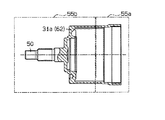
前記入力軸50が一体に形成されたフロントハウジング31aは例えばS15Cなどの機械構造用炭素鋼にて形成されている。図4に示すように、前記フロントハウジング31aの後部側は、フロントハウジング31aにおける他の部分よりもカーボン量が少なくされた磁気回路構成部55aとされている。以下、フロントハウジング31aにおける磁気回路構成部55a以外の部分を非磁気回路形成部55bという。図1に示すように、リヤハウジング31bの径方向の中間部には、非磁性材であるステンレス製の筒体51が埋設され、同筒体51は環状の非磁性部位を形成し、後述する磁路Zが形成されるようになっている。
【0022】
前記アウタケース30aはフロントハウジング31aの前端部外周において、ディファレンシャルキャリヤ22(図2参照)に対して図示しないベアリング等を介して回転可能に支持されている。また、アウタケース30aは、リヤハウジング31bの外周において、ディファレンシャルキャリヤ22(図2参照)に対して支持されたヨーク36にベアリング等を介して支持されている。
【0023】
前記インナシャフト30bは、リヤハウジング31bの中央部を液密的に貫通してフロントハウジング31a内に挿入され、軸方向への移動を規制された状態でフロントハウジング31aとリヤハウジング31bに対して相対回転可能に支持されている。インナシャフト30bには、ドライブピニオンシャフト19(図2参照)の先端部が挿入されている。なお、図1においてはドライブピニオンシャフト19は図示していない。
【0024】
図1,3に示すように、メインクラッチ機構30cは湿式多板式の摩擦クラッチ機構であって、多数のインナクラッチプレート32a及びアウタクラッチプレート32bを備えており、フロントハウジング31aの奥壁側に配設されている。
【0025】
摩擦クラッチ機構を構成する各インナクラッチプレート32aは、インナシャフト30bの外周にスプライン嵌合されて軸方向へ移動可能に組み付けられている。一方、各アウタクラッチプレート32bは、フロントハウジング31aの内周にスプライン嵌合されて軸方向へ移動可能に組み付けられている。各インナクラッチプレート32aと各アウタクラッチプレート32bは交互に位置されて互いに当接して摩擦係合するとともに、互いに離間して非係合の自由状態になる。
【0026】
パイロットクラッチ機構30dは、電磁石33、摩擦クラッチ34、及びアーマチャ35を備えている。前記電磁石33とアーマチャ35にて駆動手段が構成されている。
【0027】
図1に示すように、ヨーク36はディファレンシャルキャリヤ22(図2参照)に対して軸方向に沿って支承され、かつリヤハウジング31bの後端部の外周に対して相対回転可能に支持されている。前記ヨーク36には環状をなす電磁石33が嵌着され、同電磁石33はリヤハウジング31bの環状凹所53に嵌合されている。この結果、リヤハウジング31bとヨーク36との間に所定のクリアランスが形成されている。
【0028】
前記摩擦クラッチ34は、複数のインナクラッチプレート34a及びアウタクラッチプレート34bからなる多板式の摩擦クラッチとして構成されている。各インナクラッチプレート34aは、後述するカム機構30eを構成する第1カム部材37の外周にスプライン嵌合されて軸方向へ移動可能に組み付けられている。一方、各アウタクラッチプレート34bは、フロントハウジング31aの内周にスプライン嵌合されて軸方向へ移動可能に組み付けられている。
【0029】
各インナクラッチプレート34aと各アウタクラッチプレート34bとは交互に位置して、互いに当接して摩擦係合するとともに、互いに離間して非係合の自由状態になる。
【0030】
アーマチャ35は環状をなしており、フロントハウジング31aの内周にスプライン嵌合されて軸方向への移動可能に組み付けられている。前記アーマチャ35は摩擦クラッチ34に対して一側に位置し、摩擦クラッチ34に対向している。
【0031】
図3に示すように、前記電磁石33の電磁コイルへの通電により、ヨーク36、リヤハウジング31b、摩擦クラッチ34、アーマチャ35、摩擦クラッチ34、リヤハウジング31b、ヨーク36間、或いはヨーク36、リヤハウジング31b、フロントハウジング31aの磁気回路構成部55a(図4参照)、アーマチャ35、摩擦クラッチ34、リヤハウジング31b、ヨーク36間を循環する磁気回路Zが形成される。
【0032】
図1,3に示すように、カム機構30eは、第1カム部材37、アルミニウム材からなる第2カム部材38、及びカムフォロア39にて構成されている。
第1カム部材37及び第2カム部材38には、対向面に互いに対向する図示しないカム溝が周方向に所定間隔を保持して複数形成されている。第1カム部材37はインナシャフト30bの外周に回転可能に嵌合されるとともに、リヤハウジング31bに回転可能に支承されている。第1カム部材37の外周には、各インナクラッチプレート34aがスプライン嵌合されている。
【0033】
第2カム部材38はインナシャフト30bの外周にスプライン嵌合されており、インナシャフト30bに対して一体回転可能に組み付けられている。同第2カム部材38はメインクラッチ機構30cのインナクラッチプレート32aに対向して位置されている。前記第2カム部材38と第1カム部材37の互いに対向するカム溝には、ボール状のカムフォロア39が介在されている。
【0034】
この結果、アーマチャ35がフロントハウジング31aの内側にて摩擦クラッチ34の一側に位置し、且つ電磁石33がフロントハウジング31aの外側にてリヤハウジング31bを挟んで摩擦クラッチ34の他側に位置する。
【0035】
リヤハウジング31bはインナシャフト30bの外周に液密的かつ回転可能に嵌合された状態で、その前側壁部の周縁部にてフロントハウジング31aに螺着されている。また、リヤハウジング31bは、その後側筒部の後端部の外周にて図示しないオイルシールを介して、ディファレンシャルキャリヤ22(図2参照)に液密的かつ回転可能に支持されている。
【0036】
上記のような駆動力伝達装置11においては、パイロットクラッチ機構30dを構成する電磁石33の電磁コイルへの通電がなされていない場合には磁気回路Zは形成されず、摩擦クラッチ34は非係合状態にある。このため、パイロットクラッチ機構30dは非作動の状態にあって、カム機構30eを構成する第1カム部材37は、カムフォロア39を介して第2カム部材38と一体回転可能であり、メインクラッチ機構30cは非作動状態にある。このため、四輪駆動車12は二輪駆動の駆動モードを構成する。
【0037】
一方、電磁石33の電磁コイルへ通電されると、パイロットクラッチ機構30dには磁気回路Zが形成され、電磁石33はアーマチャ35を吸引する。このため、アーマチャ35は摩擦クラッチ34を押圧して摩擦係合させ、カム機構30eの第1カム部材37をフロントハウジング31a側へ連結させ、第2カム部材38との間に相対回転を生じさせる。この結果、カム機構30eではカムフォロア39が両カム部材37,38を互いに離間する方向へ押圧する。
【0038】
この結果、第2カム部材38はメインクラッチ機構30c側へ押圧され、メインクラッチ機構30cを摩擦クラッチ34の摩擦係合力に応じて摩擦係合させ、アウタケース30aとインナシャフト30bとの間のトルク伝達を行う。このため、四輪駆動車12はプロペラシャフト18とドライブピニオンシャフト19が非直結状態の四輪駆動の駆動モードを構成する。
【0039】
また、電磁石33の電磁コイルへの印加電流を所定の値に高めると、電磁石33のアーマチャ35に対する吸引力が増大する。そして、アーマチャ35は強く電磁石33側へ吸引され、摩擦クラッチ34の摩擦係合力を増大させ、両カム部材37,38間の相対回転を増大させる。この結果、カムフォロア39は第2カム部材38に対する押圧力を高めて、メインクラッチ機構30cを結合状態とする。このため、四輪駆動車12はプロペラシャフト18とドライブピニオンシャフト19が直結した四輪駆動の駆動モードを構成する。
【0040】
次に、フロントハウジング31aの加工法について説明する。
まず、始めに鋳造などにて形成したフロントハウジング31aを切削加工により所望の形状にする。そして、図4に示すように、フロントハウジング31aの磁気回路構成部55aを覆うように公知の防炭剤を塗布する。次に、フロントハウジング31a全体に対して公知の浸炭加工を施す。すると、前記非磁気回路形成部55bの表面は浸炭層が形成され、磁気回路構成部55aと比べてカーボン量が多くなる。そして、入力軸50に対して高周波焼き入れを行い、その後、磁気回路構成部55aに付着している防炭剤を除去する。
【0041】
この結果、フロントハウジング31aの磁気回路構成部55aには浸炭層が形成されない一方、非磁気回路形成部55bには浸炭層が形成される。
次に、上記第1実施形態のように構成された駆動力伝達装置11が特徴とする作用について説明する。
【0042】
なお、ここで構造用炭素鋼の一般的な特性を説明しておく。構造用炭素鋼はカーボン量が多いほど磁束は通過しにくい一方、一度磁束が通過すると残留磁気が帯びやすくなる特性を持っている。
【0043】
電磁石33の電磁コイルへ通電されると磁気回路Zが形成され、この際、磁気回路Zの一部であるフロントハウジング31aの磁気回路構成部55aには磁束が通過する。そして、電磁石33の電磁コイルへの通電を止めると、磁気回路構成部55aは非磁気回路形成部55bと比べてカーボン量が少ないため素早く磁気がなくなる。すると、パイロットクラッチ機構30dのアーマチャ35は残留磁気に阻まれることなく確実に摩擦クラッチ34を解除する。
【0044】
また、前記非磁気回路形成部55bである入力軸50の基端部は、磁気回路構成部55aよりもカーボン量が多いため駆動力伝達装置11としての機能を果たすのに十分な強度を有している。
【0045】
従って、上記第1実施形態の駆動力伝達装置11によれば、以下のような効果を得ることができる。
(1)本実施形態では、フロントハウジング31aにおける磁気回路構成部55aのカーボン量を非磁気回路形成部55bよりも少なくなるように形成した。従って、磁気回路構成部55aは非磁気回路形成部55bよりも残留磁気が少なくなり、アーマチャ35の作動に対する悪影響を抑制できる。加えて、フロントハウジング31aを安価な構造用炭素鋼のみで形成できるため、従来の駆動力伝達装置のフロントハウジングと比べて、材料コストを削減できると共に、溶接作業などの作業コストも削減できる。
【0046】
(2)本実施形態では、フロントハウジング31aの入力軸50に対して高周波焼き入れを施している。従って、フロントハウジング31aの入力軸50は、駆動力伝達装置11の機能を果たすのに十分な強度を得ることができる。
【0047】
(第2実施形態)
以下、本発明を具体化した第2実施形態を図1〜図4に従って説明する。なお、第2実施形態の駆動力伝達装置61は、前記第1実施形態のフロントハウジング31aの加工法を変更したフロントハウジング62を採用したものであり、前記第1実施形態と同様の構成については、同一符号を付して、その詳細な説明を省略し、異なるところを詳しく説明する。
【0048】
本実施形態の駆動力伝達装置61のフロントハウジング62の加工法について説明する。
まず、始めに鋳造などにて形成したフロントハウジング62を切削加工により所望の形状にする。この際、フロントハウジング62の磁気回路構成部55aは、後で仕上げ切削加工ができるように荒削りとしておく。次に、フロントハウジング62全体に対して公知の浸炭加工を施す。すると、フロントハウジング62の表面は浸炭層が形成され、フロントハウジング62の内部と比べてカーボン量が多くなる。
【0049】
そして、前記磁気回路構成部55aの表面に形成された浸炭層を仕上げ切削加工により除去し、フロントハウジング62の後端部内周面にリヤハウジング31bを螺着させるための雌ネジを形成する。そして、入力軸50に対して高周波焼き入れを行う。
【0050】
この結果、フロントハウジング62の磁気回路構成部55aには浸炭層が形成されない一方、非磁気回路形成部55bには浸炭層が形成される。
従って、本実施形態の駆動力伝達装置61は、前記第1実施形態の駆動力伝達装置11と同様の作用、効果を奏する。
(他の実施形態)
なお、上記各実施形態は以下のような他の実施形態に変更して具体化してもよい。
【0051】
・前記各実施形態では、フロントハウジング31a,62の加工の際、入力軸50に対して高周波焼き入れを施していた。しかし、入力軸50に対する焼き入れは高周波焼き入れに限らず、炎焼き入れにて焼き入れでもよい。
【0052】
・前記各実施形態では、フロントハウジング31a,62の磁気回路構成部55aに対して高周波焼き入れを施していたが、焼き入れを施さなくてもよい。
次に、上記各実施形態及び他の実施形態から把握できる請求項に記載した発明以外の技術的思想について、それらの効果と共に以下に記載する。
【0053】
(イ)前記外側回転部材に対して浸炭処理を行う際に、磁気回路構成部に対して防炭加工処理を施したことを特徴とする請求項1又は請求項2に記載の駆動力伝達装置。このように構成すると、外側回転部材の磁気回路構成部には浸炭層が形成されず、他の部分の表面には浸炭層が形成できる。
【0054】
(ロ)前記外側回転部材における磁気回路構成部以外の他の部分には、浸炭処理した後に焼き入れ加工を施したことを特徴とする請求項2又は(イ)に記載の駆動力伝達装置。このように構成すると、外側回転部材の磁気回路構成部以外の他の部分において、焼き入れしない場合と比べて硬化できる。
【0055】
【発明の効果】
請求項1〜3に記載の発明によれば、電磁式の駆動手段の作動を確実に行うことができ、かつ外側回転部材を構造用炭素鋼のみで形成することで外側回転部材の低コスト化、量産化ができる。
【0056】
請求項2に記載の発明によれば、磁気回路構成部に防炭加工処理を行うことで、磁気回路構成部は外側回転部材における他の部分よりカーボン量を少なくできる。
【0057】
請求項3に記載の発明によれば、磁気回路構成部を浸炭処理後、切削加工することで、磁気回路構成部は外側回転部材における他の部分よりカーボン量を少なくできる。
【図面の簡単な説明】
【図1】 第1、2実施形態における駆動力伝達装置の部分断面図。
【図2】 第1、2実施形態における駆動力伝達装置を搭載した四輪駆動車の説明図。
【図3】 第1、2実施形態における駆動力伝達装置の要部断面図。
【図4】 第1、2実施形態におけるフロントハウジングの断面図。
【符号の説明】
11,61…駆動力伝達装置、30a…外側回転部材としてのアウタケース、30b…内側回転部材としてのインナシャフト、34…摩擦クラッチ、
55a…磁気回路構成部、Z…磁気回路。[0001]
BACKGROUND OF THE INVENTION
The present invention relates to a driving force transmission device, and more particularly to a driving force transmission device having a friction clutch (electromagnetic clutch).
[0002]
[Prior art]
Conventionally, what is proposed in Japanese Utility Model Publication No. 7-14229 is known as an example of a driving force transmission device.
[0003]
This driving force transmission device includes a friction clutch (electromagnetic clutch) disposed between both inner and outer rotating members that are coaxially and relatively rotatable with each other, and an electromagnetic type that operates by energization to frictionally engage the friction clutch. The drive means is provided.
[0004]
An input shaft is integrally formed outside the outer rotating member, and the driving force of the engine is transmitted to the outer rotating member via the input shaft. The drive means is located inside the outer rotating member and faces the friction clutch; an electromagnet located outside the outer rotating member and faces the friction clutch across the side wall of the outer rotating member; It is composed of
[0005]
In the driving force transmission device, a front housing is adopted as the outer rotating member, and an inner shaft is adopted as the inner rotating member.
In the drive force transmission device, a magnetic circuit that circulates the yoke supporting the electromagnet, the front side wall of the front housing, the front housing, the armature, the friction clutch, the front side wall and the yoke is formed by energizing the electromagnetic coil of the electromagnet. Is done. Then, the armature is attracted to the friction clutch side by magnetic induction. As a result, the armature presses and frictionally engages the friction clutch, and the main clutch mechanism is actuated directly or via the cam mechanism by this friction engagement force to connect the front housing and the inner shaft so that torque can be transmitted. .
[0006]
The input shaft and the front housing are integrally formed of an iron material, and a stainless material, which is a nonmagnetic material, is welded and fixed to a portion of the front housing that faces the armature and the friction clutch.
[0007]
By the way, a front housing made of an iron material has a characteristic of having residual magnetism when energized to an electromagnetic coil of an electromagnet. However, by providing a stainless steel material in a portion of the front housing that faces the armature, the armature operates normally without being affected by residual magnetism from the front housing, and reliably transmits torque between the front housing and the inner shaft. Has been.
[0008]
[Problems to be solved by the invention]
However, in the above driving force transmission device, since the stainless steel material is partially welded and fixed to the front housing made of iron material, the work cost for welding is high. Further, the stainless steel material to be fixed by welding has a complicated shape and the material itself is expensive, so that the material cost is high. Although it is conceivable that the input shaft and the entire front housing are made of stainless steel, there is a problem that the material cost increases.
[0009]
Accordingly, the present invention has been made in view of the above-described circumstances, and the object thereof is to reliably operate the electromagnetic driving means, and the outer rotating member is formed only from structural carbon steel. Accordingly, an object of the present invention is to provide a driving force transmission device capable of reducing the cost and mass production of the outer rotating member.
[0010]
[Means for Solving the Problems]
In order to achieve the above object, according to the first aspect of the present invention, there is provided a friction clutch disposed between the inner and outer rotating members positioned so as to be rotatable relative to each other, and the friction clutch engaged by energization to frictionally engage the friction clutch. In the driving force transmission device including the electromagnetic driving means, the outer rotating member includes a magnetic circuit component that becomes a part of a magnetic circuit by the driving means when energized, and the outer rotating member is structural carbon. The gist is that the magnetic circuit constituent part is made of steel and the amount of carbon in the outer rotating member is smaller than that in other parts.
[0011]
The gist of the invention according to claim 2 is that, in the driving force transmission device according to claim 1, the magnetic circuit component is subjected to a carbon-proofing treatment.
The gist of the invention according to claim 3 is that, in the driving force transmission device according to claim 1, the magnetic circuit component is cut after carburizing.
(Function)
Therefore, in the first aspect of the present invention, the outer rotating member is made of structural carbon steel, but the magnetic circuit constituent part has a smaller amount of carbon than other parts, so that the residual magnetism is reduced. Is hard to remain. As a result, when the energization is stopped after the magnetic circuit is formed by energizing the drive means and the friction clutch is frictionally engaged, the residual magnetism hardly remains in the magnetic circuit component. Release the engagement securely. In addition, since the carbon portion of the outer rotating member other than the magnetic circuit component has a larger amount of carbon than the magnetic circuit component, sufficient strength can be obtained to fulfill the function as a driving force transmission device.
[0012]
In addition to the effect | action of Claim 1, in the invention of Claim 2, since the said magnetic circuit structure part performs a charcoal-proof process, the amount of carbon is made smaller than the other part in an outer side rotation member.
[0013]
In addition to the effect | action of Claim 1, in the invention of Claim 3, after the said magnetic circuit structure part carburizes, it cuts the amount of carbons from the other part in an outer side rotation member by cutting.
[0014]
DETAILED DESCRIPTION OF THE INVENTION
(First embodiment)
Hereinafter, an embodiment embodying the present invention will be described with reference to FIGS.
[0015]
FIG. 1 shows a driving force transmission device according to an embodiment of the present invention. As shown in FIG. 2, the driving
[0016]
The four-
The driving force of the
[0017]
A driving
[0018]
The driving
[0019]
Next, the driving
As shown in FIG. 1, the driving
[0020]
The
[0021]
The
[0022]
The
[0023]
The
[0024]
As shown in FIGS. 1 and 3, the main
[0025]
Each inner
[0026]
The
[0027]
As shown in FIG. 1, the
[0028]
The
[0029]
The inner
[0030]
The
[0031]
As shown in FIG. 3, by energizing the electromagnetic coil of the
[0032]
As shown in FIGS. 1 and 3, the
In the
[0033]
The
[0034]
As a result, the
[0035]
The
[0036]
In the driving
[0037]
On the other hand, when the electromagnetic coil of the
[0038]
As a result, the
[0039]
Further, when the current applied to the electromagnetic coil of the
[0040]
Next, a method for processing the
First, the
[0041]
As a result, a carburized layer is not formed on the
Next, an operation characterized by the driving
[0042]
Here, general characteristics of structural carbon steel will be described. Structural carbon steel has the characteristic that, as the amount of carbon increases, the magnetic flux is less likely to pass, but once the magnetic flux passes, the residual magnetism is more likely to occur.
[0043]
When the electromagnetic coil of the
[0044]
Further, the base end portion of the
[0045]
Therefore, according to the driving
(1) In this embodiment, the carbon amount of the
[0046]
(2) In the present embodiment, induction hardening is applied to the
[0047]
(Second Embodiment)
A second embodiment embodying the present invention will be described below with reference to FIGS. The driving
[0048]
A processing method of the
First, the
[0049]
Then, the carburized layer formed on the surface of the
[0050]
As a result, a carburized layer is not formed on the
Therefore, the driving
(Other embodiments)
Each of the above embodiments may be embodied by changing to the following other embodiments.
[0051]
In each of the above embodiments, the
[0052]
In each of the embodiments described above, the induction hardening is performed on the
Next, technical ideas other than the invention described in the claims that can be grasped from the respective embodiments and other embodiments will be described below together with their effects.
[0053]
(A) When the carburizing process is performed on the outer rotating member, the carburizing process is performed on the magnetic circuit constituent part. The driving force transmission device according to claim 1 or 2, . If comprised in this way, a carburized layer will not be formed in the magnetic circuit structure part of an outer side rotation member, but a carburized layer can be formed in the surface of another part.
[0054]
(B) The driving force transmission device according to claim 2 or (a), wherein the outer rotating member other than the magnetic circuit component is subjected to a quenching process after carburizing. If comprised in this way, in other parts other than the magnetic circuit structure part of an outer side rotation member, it can harden | cure compared with the case where it does not quench.
[0055]
【The invention's effect】
According to the first to third aspects of the present invention, the operation of the electromagnetic driving means can be reliably performed, and the cost of the outer rotating member can be reduced by forming the outer rotating member only with structural carbon steel. Can be mass-produced.
[0056]
According to the second aspect of the present invention, the magnetic circuit component can reduce the amount of carbon as compared with other portions of the outer rotating member by performing the carbon-proof processing on the magnetic circuit component.
[0057]
According to the third aspect of the invention, by cutting the magnetic circuit constituent part after carburizing, the magnetic circuit constituent part can reduce the amount of carbon compared to other parts of the outer rotating member.
[Brief description of the drawings]
FIG. 1 is a partial cross-sectional view of a driving force transmission device according to first and second embodiments.
FIG. 2 is an explanatory diagram of a four-wheel drive vehicle equipped with the driving force transmission device according to the first and second embodiments.
FIG. 3 is a cross-sectional view of a main part of a driving force transmission device according to first and second embodiments.
FIG. 4 is a cross-sectional view of a front housing in the first and second embodiments.
[Explanation of symbols]
DESCRIPTION OF
55a ... Magnetic circuit component, Z ... Magnetic circuit.
Claims (3)
前記外側回転部材には、前記通電時に駆動手段によって磁気回路の一部となる磁気回路構成部を含み、
前記外側回転部材を構造用炭素鋼にて形成し、同外側回転部材のうち、前記磁気回路構成部は、他の部分に比してカーボン量を少なくしたことを特徴とする駆動力伝達装置。In a driving force transmission device comprising a friction clutch disposed between inner and outer rotating members positioned so as to be relatively rotatable with each other, and an electromagnetic driving means that is operated by energization to frictionally engage the friction clutch.
The outer rotating member includes a magnetic circuit component that becomes a part of the magnetic circuit by the driving means during the energization,
The driving force transmitting device according to claim 1, wherein the outer rotating member is made of structural carbon steel, and the magnetic circuit component of the outer rotating member has a smaller amount of carbon than other portions.
Priority Applications (1)
| Application Number | Priority Date | Filing Date | Title |
|---|---|---|---|
| JP2000254426A JP3777399B2 (en) | 2000-08-24 | 2000-08-24 | Driving force transmission device |
Applications Claiming Priority (1)
| Application Number | Priority Date | Filing Date | Title |
|---|---|---|---|
| JP2000254426A JP3777399B2 (en) | 2000-08-24 | 2000-08-24 | Driving force transmission device |
Publications (2)
| Publication Number | Publication Date |
|---|---|
| JP2002070889A JP2002070889A (en) | 2002-03-08 |
| JP3777399B2 true JP3777399B2 (en) | 2006-05-24 |
Family
ID=18743377
Family Applications (1)
| Application Number | Title | Priority Date | Filing Date |
|---|---|---|---|
| JP2000254426A Expired - Lifetime JP3777399B2 (en) | 2000-08-24 | 2000-08-24 | Driving force transmission device |
Country Status (1)
| Country | Link |
|---|---|
| JP (1) | JP3777399B2 (en) |
Families Citing this family (2)
| Publication number | Priority date | Publication date | Assignee | Title |
|---|---|---|---|---|
| DE102007031078B4 (en) * | 2006-07-05 | 2021-02-04 | Neumayer Tekfor Engineering Gmbh | Fixed constant velocity ball joint as a counter track joint and method of production |
| JP2014114833A (en) * | 2012-12-06 | 2014-06-26 | Jtekt Corp | Driving force transmission device |
-
2000
- 2000-08-24 JP JP2000254426A patent/JP3777399B2/en not_active Expired - Lifetime
Also Published As
| Publication number | Publication date |
|---|---|
| JP2002070889A (en) | 2002-03-08 |
Similar Documents
| Publication | Publication Date | Title |
|---|---|---|
| JP2002048157A (en) | Driving force transmission | |
| JP2009109020A (en) | Assembly method of drive force transmitting equipment using electromagnetic clutch | |
| JP3777399B2 (en) | Driving force transmission device | |
| JP4024500B2 (en) | Electromagnetic brake | |
| JP4247568B2 (en) | Driving force transmission device | |
| JP4202587B2 (en) | Driving force transmission device and adjustment method thereof | |
| JP3777402B2 (en) | Driving force transmission device | |
| JP3243438B2 (en) | Driving force transmission device | |
| JP3256737B2 (en) | Driving force transmission device | |
| JP3243437B2 (en) | Driving force transmission device | |
| JP3027806B2 (en) | Driving force transmission device | |
| JP4096679B2 (en) | Manufacturing method of magnetic path forming member | |
| JP4051868B2 (en) | Driving force transmission device and torque transmission adjustment method for driving force transmission device | |
| JP4006960B2 (en) | Method for manufacturing electromagnetic pilot clutch device | |
| JP3890169B2 (en) | Driving force transmission device with electromagnetic actuation mechanism | |
| JPH11287258A (en) | Electromagnetic friction clutch | |
| JP3574756B2 (en) | Magnetic path forming member of electromagnetic clutch | |
| JP3784040B2 (en) | Driving force transmission device for vehicle | |
| JP4192955B2 (en) | Driving force transmission device | |
| JP2005036863A (en) | Friction clutch and driving force transmission device | |
| JPH11208303A (en) | Driving force transmitting device for vehicle | |
| JP2000081054A (en) | Electromagnetic clutch device | |
| JP2005121116A (en) | Driving force transmitting device | |
| JPH11303911A (en) | Clutch plate and electromagnetic friction clutch using it | |
| JP2009103143A (en) | Driving force transmitting device |
Legal Events
| Date | Code | Title | Description |
|---|---|---|---|
| TRDD | Decision of grant or rejection written | ||
| A01 | Written decision to grant a patent or to grant a registration (utility model) |
Free format text: JAPANESE INTERMEDIATE CODE: A01 Effective date: 20060117 |
|
| A61 | First payment of annual fees (during grant procedure) |
Free format text: JAPANESE INTERMEDIATE CODE: A61 Effective date: 20060118 |
|
| A711 | Notification of change in applicant |
Free format text: JAPANESE INTERMEDIATE CODE: A712 Effective date: 20060118 |
|
| R150 | Certificate of patent or registration of utility model |
Ref document number: 3777399 Country of ref document: JP Free format text: JAPANESE INTERMEDIATE CODE: R150 Free format text: JAPANESE INTERMEDIATE CODE: R150 |
|
| FPAY | Renewal fee payment (event date is renewal date of database) |
Free format text: PAYMENT UNTIL: 20090310 Year of fee payment: 3 |
|
| FPAY | Renewal fee payment (event date is renewal date of database) |
Free format text: PAYMENT UNTIL: 20100310 Year of fee payment: 4 |
|
| FPAY | Renewal fee payment (event date is renewal date of database) |
Free format text: PAYMENT UNTIL: 20110310 Year of fee payment: 5 |
|
| FPAY | Renewal fee payment (event date is renewal date of database) |
Free format text: PAYMENT UNTIL: 20120310 Year of fee payment: 6 |
|
| FPAY | Renewal fee payment (event date is renewal date of database) |
Free format text: PAYMENT UNTIL: 20120310 Year of fee payment: 6 |
|
| FPAY | Renewal fee payment (event date is renewal date of database) |
Free format text: PAYMENT UNTIL: 20130310 Year of fee payment: 7 |
|
| FPAY | Renewal fee payment (event date is renewal date of database) |
Free format text: PAYMENT UNTIL: 20140310 Year of fee payment: 8 |
|
| EXPY | Cancellation because of completion of term |