JP3774840B2 - rice cooker - Google Patents
rice cookerInfo
- Publication number
- JP3774840B2 JP3774840B2 JP2000027066A JP2000027066A JP3774840B2 JP 3774840 B2 JP3774840 B2 JP 3774840B2 JP 2000027066 A JP2000027066 A JP 2000027066A JP 2000027066 A JP2000027066 A JP 2000027066A JP 3774840 B2 JP3774840 B2 JP 3774840B2
- Authority
- JP
- Japan
- Prior art keywords
- lid
- hinge
- latch
- spring
- main body
- Prior art date
- Legal status (The legal status is an assumption and is not a legal conclusion. Google has not performed a legal analysis and makes no representation as to the accuracy of the status listed.)
- Expired - Lifetime
Links
Images


Description
【0001】
【産業上の利用分野】
本発明は炊飯器に係わり、特に、閉じられた蓋体を本体に係止するラッチ機構やラッチ機構を解除すると蓋体がヒンジ軸を支点に回動して自動的に開放されるヒンジ機構の構造に関するものである。
【0002】
【従来の技術】
図11乃至図14は従来の炊飯器を示すものであり、図において、1は炊飯器、2はケースの本体、2a は本体2の枠板、3は蓋体、3a は蓋枠、3b は外蓋、3c は蓋パッキン、3d は反射板である。4は外釜、5は遮熱板、6は内釜、6a は内釜6の水平方向に伸びたフランジ部、7は炊飯ヒータ、8は温度センサ、9はコードリールである。10はラッチ機構、10a は押し釦、10b は掛け金、10c はスプリングである。スプリング10c は押し釦10を本体2の側面に露出させ、掛け金10b を蓋枠3a に係止させる。
【0003】
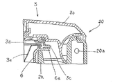
20はヒンジ機構(図12)、20a はヒンジ軸、20b は中空軸、20c はヒンジバネ、20d は金属の受け板、20e は固定ネジで、これらは対構造に作られている。受け板20d は鍵形に折り曲げられて水平部が固定ネジ20e で固定されて、底面がヒンジバネ20c のバネ受けになっている。また、垂直部の先端の切欠き20f は、中空軸20b の溝20g に係合して移動を規制している。20h は円弧部20i を形成した円弧軸受け、20j はスタッド軸受け、20k は4個の固定軸受けである。円弧軸受け20h とスタッド軸受け20j は蓋体3側に設けられ、固定軸受け20k は本体2側に形成されている。図15の30は制動機構である。30a は装着孔、30b はネジ孔、30c は調節ネジ、30d は可動片、30e は調節バネ、30f は押圧片である。
【0004】
上記のような構成の炊飯器において、炊飯ヒータ7の発熱によって内釜6が加熱される。内釜6の加熱で内部の水が沸騰し、水がなくなると温度が急激に上昇して炊飯温度に達してから御飯が炊き上げられる。御飯が炊き上げられてラッチ機構10の押し釦10a を押すと掛け金10b が外れ、ヒンジバネ20c により蓋体3がヒンジ軸20a を支点に回転して自動的に開放される。このとき、蓋体3の回転に連れて円弧軸受け20h も同方向に回転し、円弧部20i が制動機構30の調節バネ30e に逆らって押し付ける。円弧部20i の押付け力は回転角に比例して強くなって、蓋体3の急激な開放が抑制される。
【0005】
また、図14に要部の拡大断面図が示されている。図14で図11乃至図13に対応する部分は同様の動作と同様の機能を果たすので、同じ符号を付して再説明は省略する。なお、3e は内蓋である。
【0006】
【発明が解決しようとする課題】
以上のように、ヒンジ機構20には、金属板を折り曲げた複雑な一対の受け板20d やこの受け板20d を固定する固定ネジ20e 等が用いられている。したがって、蓋体3の全体の重さも重くなって、重量に見合ったバネ定数の大きいヒンジバネ20c を用いる必要に迫られる恐れがある。しかも、部品点数も増えて、それだけ炊飯器を製作する為の工数が増加してコスト高になる等の問題点があった。
【0007】
この発明は上記のような問題点を解消するためになされたもので、構造が簡単なヒンジ機構を備え組立性が容易で全体の製作費が安価な炊飯器を実現することを目的とするものである。
【0008】
【課題を解決するための手段】
この発明は、内釜を加熱する加熱手段が内部に設けられ、前記内釜を着脱可能に装着した本体と、該本体の上部を開閉する蓋体と、前記本体の上部に設けられ、ヒンジ軸を回動軸として前記蓋体を開蓋方向に付勢するヒンジバネを有するヒンジ機構と、該ヒンジ機構と対向する側に設けた操作手段によりラッチを係合離脱させて蓋体を開閉するラッチ機構を備え、
前記蓋体に前記ヒンジバネの一端を係止するための突片を設け、該突片が、端部を開口したL字形又は渦巻き形の挿入溝を有し、該挿入溝の前記端部の開口から前記ヒンジバネの一端が挿入されて係止されるものである。
【0009】
【作用】
ヒンジ軸から延設したヒンジバネの一端を本体側に係止し、他端を蓋体に設けた係止部の開口部より挿入し、ヒンジバネの反発トルクにより係止溝の上端に係止する。
【0010】
【実施例】
実施例1
図1は本発明実施例の炊飯器の構成説明図である。本発明実施例において、従来の炊飯器と同じ部分に同一符号を付したものもあるが、構造と動作において相違するものもあるので、一部重複するが少し詳しく説明する。
【0011】
図1において、1は炊飯器、2はケースの本体、2a は本体2の枠板である。3は本体2の上部を覆う蓋体である。蓋体3は蓋枠3a と外蓋3b とを備え、蓋枠3a の上部に外蓋3b が取り付けられている。3c は蓋パッキン、3d は反射板、3e は内蓋、3f は蒸気筒である。蓋パッキン3c は耐熱性の弾性体で環状に作られていて、蓋枠3a の溝に挿入されて反射板3d の周縁部で押し付けられて蓋枠3a に固定されている。また、内蓋3e は取り外し自在に、反射板3d の下側に装着される。
【0012】
4は本体2の内部に取り付けられた外釜、5は遮熱板、6は内釜である。外釜4と本体2との隙間の上部は、枠板2a で覆われている。内釜6は外釜4の内部で枠板2a にフランジ部6a が載置され、本体2に取出し自在に収納される。内釜6の開放端は図2にも示すように2段に折り曲げられ、先端のフランジ部6a は斜め上方に張出して内側が低く傾いた傾斜面6b が形成されている。内釜6のフランジ部6a は蓋体3が閉められているときに蓋パッキン3c に圧接して、蒸気が洩れないようになっている。また、内釜6内には米の容量に対して適量な水量を示す標準的な水位線が刻設され、炊飯時の便に供されている。7は炊飯ヒータ、8は温度センサ、9はコードリールである。10は蓋体3を開閉するラッチ機構である。
【0013】
ラッチ機構10の構造が、図3に拡大して示されている。11はラッチ機構10のラッチ釦、12は釦バネ、13は釦軸である。なお、図1ではラッチ釦11が本体2の側面に露出して図示されているが、基本的には凹部2b に設けた図3の構造が採用される。14はラッチ、15は突起、16はラッチバネ、17はラッチ軸である。釦バネ12は本体2と釦軸13との間に懸張されて、ラッチ釦11に下に引っ張るバネ圧を加える。また、ラッチバネ16はラッチ軸17に巻き回され、巻き込まれた螺旋の両端が枠板2a と突起15に係止されてラッチ14にラッチ軸17を中心に反時計方向の力を加えている。そして、蓋体3の閉止状態では、ラッチ14の鉤形部が蓋枠3a の折曲部に引っ掛かって蓋体3をロックしている。
【0014】
図4に蓋体3を構成する蓋枠3a ,外蓋3b と内釜6及び本体2の枠板2a の各斜視図が示されている。枠板2a と蓋枠3a 及び外蓋3b は、いずれも合成樹脂で図示のように成型されている。また、図5はヒンジ機構20とこのヒンジ機構20に付随する制動機構30の分解斜視図である。図示のように、前述の図12及び図13と同様に2箇所で蓋体3を本体2上に支持する対構造の構成になっている。
【0015】
図4と図5において、21はヒンジ軸、22は中空軸、23はヒンジバネである。本発明の実施例では前記と異なり鍵形に折り曲げた金属板の受け板20d は省略され、中空軸20b にも溝20g が設けられていない。24は受け板20d に代わるバネ受けで、蓋枠3a の背面側に設けられ、ヒンジバネ23を蓋枠3aに係止するものである。24a はバネ受け24を構成する平行な2つの突片、24b は突片24a に形成され端部を開口したL字溝である。
【0016】
左右のヒンジバネ23の螺旋部には中空軸22が挿入されて枠板2a に設けられた装着部20A にセットされ、矢印のように2本のヒンジ軸21が内側から挿通される(図5)。そして、下に伸びたヒンジバネ23の一端は本体2側に係止されて螺旋部が巻き込まれてから、他端が横からL字溝24b に差し込まれる。巻き込まれたヒンジバネ23により、常時蓋体3に開放させる方向のトルクが与えられる。
【0017】
制動機構30は本発明でも蓋枠3a の背面側に設けられ蓋体3と一体にヒンジ軸21を支点に回転する円弧軸受け31の変位が、制動作用に利用される。ただし、ここでは円弧軸受け31の円弧部31a が、最初は幅が狭く蓋体3の回転角が大きさに応じて徐々に広くなる台形状に形成されている(図7参照)。32は2組のローラ、33はローラ軸である。ローラ32は弾性体で作られて枠板2a の装着部30A にセットされて、共に横からローラ軸33が挿通されて枠板2a に取り付けられる。装着部30A に取付けられた2組のローラ32は、それぞれ蓋体3側の円弧軸受け31に対向するようになっている(図7参照)。
【0018】
図1において、40は蓋体3に取付けられた操作部、41は操作部40における操作シートである。43はカバー、44はプリント基板、45はプリント基板44上に取り付けられた表示器等の回路素子、46はプリント基板44から導出された複数のリード線である。カバー43は蓋体3に形成された隔壁に圧接して、内部のプリント基板44等を密閉して収容する。
【0019】
このような構成の本発明の炊飯器の動作を、次に説明する。
内釜6に研いだ米と指示された適量の水を入れて、内蓋3e を被せて蓋体3を閉める。次に、コードリール9を引き出して、プラグを100Vの電源のコンセントに接続する。蓋体3の表面の操作部40の表示を見ながら、操作シート41を操作して食事の時刻を予約設定する。予約した食事の時刻に対応する炊飯の開始時刻になると、マイコンのタイマが働いてスイッチが入り炊飯ヒータ7が通電する。通電で炊飯ヒータ7が発熱して、内釜6の内部の水と米を下から加熱する。
【0020】
炊飯ヒータ7の加熱によって炊飯が始まり、内釜6内の水の温度が上昇して蒸気が発生する。炊飯が進んで水が沸騰し内釜6の水分が少なくなって温度が急激に上昇すると、温度センサ8が働いて炊飯ヒータ7の通電が自動的に停止される。この結果、米が内釜6内で炊き上がり、予約した時刻に御飯が炊けて盛り付けが始められることになる。
【0021】
ここで、本体2の側面の凹部2b に設けたラッチ釦11をラッチバネ16に抗して押し付けると、ラッチ14の鉤形部がラッチ軸17を中心に時計方向に回動して蓋枠3a の折曲部から外れる。蓋体3には常時ヒンジバネ23のバネ圧が与えられているので、自由になった蓋体3が上方(ここでは時計方向)に回動する。蓋体3の開放が開始して或る角度まで開くと、円弧軸受け31が制動機構30の2つのローラ32の間に割り込み始める。
【0022】
このため、ヒンジバネ23のバネ圧を受けて開放される蓋体3にブレーキが掛り、蓋体3がゆっくり回動する。円弧軸受け31の円弧部31a が台形状に形成されて回転に連れて割込み深度が深くなり、蓋体3が全開される95度に近付くほど開放速度が緩慢になる。よって、蓋体3の開放に基づくショックが和らげられ、本体2の動揺が防止される。このときの円弧軸受け31と一対のローラ32の相対的な関係が、図6乃至図9に示されている。図6と7は円弧軸受け31の割込みの初期を示し、図8と図9に割込みの終期の状態が示されている。
【0023】
盛り付けが終って全開の蓋体3の開放端に反時計方向の力を加えれば、蓋体3がヒンジ軸21を中心に同方向に回動する。そして、蓋枠3a の折曲部がラッチ14に係止されて、図1及び図3に示す状態に戻って蓋体3がロックされて本体2の上部が閉鎖される。
【0024】
一方、炊飯中に発生する水蒸気や水の沸騰に伴って、蒸気が内釜6内に発生する。発生した蒸気の大部分は蒸気筒3f から大気に開放される。上昇した一部の蒸気は内蓋3e を押し上げて図10に示すように、内蓋3e の周辺の隙間から蓋パッキン3c の付近にまで侵入する。侵入した蒸気は蓋パッキン3c や反射板3d に付着し、多量の水滴になって内釜6の方向に落下する。そして、落下した水滴はフランジ部6a の傾斜面6b に沿って流下し、内釜6の内部に流れ込んで外部への流出が防止される。
【0025】
なお、上述の実施例では炊飯ヒータを発熱して、輻射熱で内釜を加熱して炊飯する電熱形の炊飯器を例示して説明したが、加熱コイルの電磁誘導作用で釜を発熱させる誘導加熱形の炊飯器にも本発明を適用することができる。また、図5では、ヒンジバネ23の端部をL字溝24b に横から挿入する構成で説明したが、突片24a に渦巻き形の挿入溝を設けて、この挿入溝にヒンジバネ23の端部を差し込んでもよく、要するにヒンジバネ23の端部が係止される開放形の係止溝であれば必ずしもL字形に限られるものではない。
【0026】
【発明の効果】
この発明に係る炊飯器は、蓋体にヒンジバネの一端を係止するための突片を設け、突片が、端部を開口したL字形又は渦巻き形の挿入溝を有し、挿入溝の端部の開口からヒンジバネの一端が挿入されて係止されるようにしたので、ヒンジバネの受け板を必要とせず、またヒンジバネの着脱が容易となり部品点数が少なく炊飯器を製作する為の工数が削減され製作費が安価となる。
【図面の簡単な説明】
【図1】本発明実施例の炊飯器の構成説明図である。
【図2】図1の内釜の構成を示す側面図である。
【図3】図1のラッチ機構の断面図である。
【図4】図1の蓋体等の斜視図である。
【図5】図1のヒンジ機構と制動機構の分解斜視図である。
【図6】制動機構の動作を示す側面図である。
【図7】制動機構の動作を示す正面図である。
【図8】制動機構の動作を示す別の側面図である。
【図9】制動機構の動作を示す別の正面図である。
【図10】炊飯中の動作を示す断面図である。
【図11】従来の炊飯器の構成説明図である。
【図12】図11のヒンジ機構の分解斜視図である。
【図13】図11の制動機構の断面図である。
【図14】従来の炊飯器の要部の拡大断面図である。
【符号の説明】
1 炊飯器
2 ケースの本体
2a 枠板
3 蓋体
3a 蓋枠
3b 外蓋
3c 蓋パッキン
3d 反射板
3e 内蓋
3f 蒸気筒
6 内釜
6a フランジ部
6b 傾斜面
10 ラッチ機構
11 ラッチ釦
12 釦バネ
13 釦軸
14 ラッチ
16 ラッチバネ
17 ラッチ軸
18 ダイヤル
20 ヒンジ機構
21 ヒンジ軸
22 中空軸
23 ヒンジバネ
24 バネ受け
24a 突片
24b L字溝
30 制動機構
31 円弧軸受け
31a 円弧部
32 ローラ
33 ローラ軸
34 弾性体
34a 突出部[0001]
[Industrial application fields]
The present invention relates to a rice cooker, and in particular, a latch mechanism for locking a closed lid to the main body or a hinge mechanism that automatically opens when the lid rotates about a hinge shaft when the latch mechanism is released. Concerning structure.
[0002]
[Prior art]
11 to 14 show a conventional rice cooker. In the figure, 1 is a rice cooker, 2 is a main body of the case, 2a is a frame plate of the
[0003]
20 is a hinge mechanism (FIG. 12), 20a is a hinge shaft, 20b is a hollow shaft, 20c is a hinge spring, 20d is a metal backing plate, and 20e is a fixing screw. The
[0004]
In the rice cooker configured as described above, the
[0005]
Moreover, the expanded sectional view of the principal part is shown by FIG. In FIG. 14, the portions corresponding to FIGS. 11 to 13 perform the same functions as the similar operations, and therefore, the same reference numerals are given and the re-explanation is omitted. 3e is an inner lid.
[0006]
[Problems to be solved by the invention]
As described above, the
[0007]
The present invention has been made to solve the above-described problems, and aims to realize a rice cooker having a hinge mechanism with a simple structure, easy to assemble, and low in overall production cost. It is.
[0008]
[Means for Solving the Problems]
The present invention includes a heating means for heating the inner hook, a main body on which the inner hook is detachably mounted, a lid for opening and closing the upper portion of the main body, an upper portion of the main body, and a hinge shaft. A hinge mechanism having a hinge spring for urging the lid body in the opening direction with the rotation axis as a rotation axis, and a latch mechanism for opening and closing the lid body by disengaging the latch by operating means provided on the side facing the hinge mechanism With
A protrusion for locking one end of the hinge spring is provided on the lid, and the protrusion has an L-shaped or spiral insertion groove having an open end, and the opening of the end of the insertion groove is open. The one end of the hinge spring is inserted and locked.
[0009]
[Action]
One end of the hinge spring extending from the hinge shaft is locked to the main body side, the other end is inserted from the opening of the locking portion provided on the lid, and locked to the upper end of the locking groove by the repulsive torque of the hinge spring.
[0010]
【Example】
Example 1
FIG. 1 is a diagram illustrating the configuration of a rice cooker according to an embodiment of the present invention. In some embodiments of the present invention, the same parts as those in the conventional rice cooker are denoted by the same reference numerals, but there are also parts that are different in structure and operation.
[0011]
In FIG. 1, 1 is a rice cooker, 2 is a case main body, and 2 a is a frame plate of the
[0012]
4 is an outer hook attached to the inside of the
[0013]
The structure of the
[0014]
FIG. 4 is a perspective view of the
[0015]
4 and 5, 21 is a hinge shaft, 22 is a hollow shaft, and 23 is a hinge spring. In the embodiment of the present invention, unlike the above, the metal
[0016]
A
[0017]
In the present invention, the
[0018]
In FIG. 1,
[0019]
Next, the operation of the rice cooker of the present invention having such a configuration will be described.
Put an appropriate amount of water instructed to sharpen rice into the
[0020]
Cooking of rice begins by heating of the
[0021]
Here, when the latch button 11 provided in the
[0022]
For this reason, a brake is applied to the
[0023]
If the counterclockwise force is applied to the open end of the fully
[0024]
On the other hand, steam is generated in the
[0025]
In the above-described embodiment, the electric heating rice cooker that generates heat by heating the rice cooker and heats the inner pot with radiant heat is described as an example, but induction heating that generates heat by electromagnetic induction of the heating coil is described. The present invention can also be applied to shaped rice cookers. Further, in FIG. 5, have been described in the configuration of inserting the lateral ends of the
[0026]
【The invention's effect】
The rice cooker according to the present invention is provided with a projecting piece for locking one end of the hinge spring on the lid, and the projecting piece has an L-shaped or spiral-shaped insertion groove having an open end, and the end of the insertion groove Since one end of the hinge spring is inserted and locked from the opening of the part, there is no need for a hinge spring receiving plate , and the hinge spring is easy to attach and detach, reducing the number of parts and reducing the man-hours for producing a rice cooker The production cost is low.
[Brief description of the drawings]
BRIEF DESCRIPTION OF DRAWINGS FIG. 1 is a diagram illustrating the configuration of a rice cooker according to an embodiment of the present invention.
FIG. 2 is a side view showing the configuration of the inner hook in FIG. 1;
3 is a cross-sectional view of the latch mechanism of FIG. 1. FIG.
4 is a perspective view of the lid body and the like shown in FIG. 1. FIG.
FIG. 5 is an exploded perspective view of the hinge mechanism and the brake mechanism of FIG. 1;
FIG. 6 is a side view showing the operation of the braking mechanism.
FIG. 7 is a front view showing the operation of the braking mechanism.
FIG. 8 is another side view showing the operation of the braking mechanism.
FIG. 9 is another front view showing the operation of the braking mechanism.
FIG. 10 is a cross-sectional view showing the operation during rice cooking.
FIG. 11 is a diagram illustrating the configuration of a conventional rice cooker.
12 is an exploded perspective view of the hinge mechanism of FIG. 11. FIG.
13 is a cross-sectional view of the braking mechanism of FIG.
FIG. 14 is an enlarged cross-sectional view of a main part of a conventional rice cooker.
[Explanation of symbols]
DESCRIPTION OF SYMBOLS 1
Claims (1)
前記蓋体に前記ヒンジバネの一端を係止するための突片を設け、該突片が、端部を開口したL字形又は渦巻き形の挿入溝を有し、該挿入溝の前記端部の開口から前記ヒンジバネの一端が挿入されて係止されることを特徴とする炊飯器。Heating means for heating the inner hook is provided inside, a main body on which the inner hook is detachably mounted, a lid body for opening and closing the upper part of the main body, an upper part of the main body, and a hinge shaft as a rotation axis A hinge mechanism having a hinge spring that biases the lid in the opening direction, and a latch mechanism that opens and closes the lid by disengaging the latch by operating means provided on the side facing the hinge mechanism,
A protrusion for locking one end of the hinge spring is provided on the lid, and the protrusion has an L-shaped or spiral insertion groove having an open end, and the opening of the end of the insertion groove is open. The rice cooker is characterized in that one end of the hinge spring is inserted and locked.
Priority Applications (1)
| Application Number | Priority Date | Filing Date | Title |
|---|---|---|---|
| JP2000027066A JP3774840B2 (en) | 1992-05-26 | 2000-02-04 | rice cooker |
Applications Claiming Priority (2)
| Application Number | Priority Date | Filing Date | Title |
|---|---|---|---|
| JP13341292A JP3275210B2 (en) | 1992-05-26 | 1992-05-26 | rice cooker |
| JP2000027066A JP3774840B2 (en) | 1992-05-26 | 2000-02-04 | rice cooker |
Related Parent Applications (1)
| Application Number | Title | Priority Date | Filing Date |
|---|---|---|---|
| JP13341292A Division JP3275210B2 (en) | 1992-05-26 | 1992-05-26 | rice cooker |
Publications (2)
| Publication Number | Publication Date |
|---|---|
| JP2000197562A JP2000197562A (en) | 2000-07-18 |
| JP3774840B2 true JP3774840B2 (en) | 2006-05-17 |
Family
ID=15104167
Family Applications (2)
| Application Number | Title | Priority Date | Filing Date |
|---|---|---|---|
| JP13341292A Expired - Lifetime JP3275210B2 (en) | 1992-05-26 | 1992-05-26 | rice cooker |
| JP2000027066A Expired - Lifetime JP3774840B2 (en) | 1992-05-26 | 2000-02-04 | rice cooker |
Family Applications Before (1)
| Application Number | Title | Priority Date | Filing Date |
|---|---|---|---|
| JP13341292A Expired - Lifetime JP3275210B2 (en) | 1992-05-26 | 1992-05-26 | rice cooker |
Country Status (1)
| Country | Link |
|---|---|
| JP (2) | JP3275210B2 (en) |
Families Citing this family (5)
| Publication number | Priority date | Publication date | Assignee | Title |
|---|---|---|---|---|
| JP5294784B2 (en) * | 2008-10-06 | 2013-09-18 | 三菱電機株式会社 | rice cooker |
| JP6155805B2 (en) * | 2013-04-25 | 2017-07-05 | タイガー魔法瓶株式会社 | Cooking device |
| JP6530515B2 (en) * | 2015-12-28 | 2019-06-12 | 佛山市▲順▼▲徳▼区美的▲電▼▲熱▼▲電▼器制造有限公司Foshan Shunde Midea Electrical Heating Appliances Manufacturing Co.,Limited | Wireless power supply communication circuit for electric cooker and electric cooker |
| CN110811298B (en) * | 2017-11-03 | 2021-09-10 | 上海爱餐机器人(集团)有限公司 | Frying pan combination device for realizing quick replacement of frying pan |
| CN112641329B (en) * | 2021-01-14 | 2022-04-26 | 汉威泰(广州)电器制造有限公司 | Safe electric kettle with heat conduction response function |
-
1992
- 1992-05-26 JP JP13341292A patent/JP3275210B2/en not_active Expired - Lifetime
-
2000
- 2000-02-04 JP JP2000027066A patent/JP3774840B2/en not_active Expired - Lifetime
Also Published As
| Publication number | Publication date |
|---|---|
| JPH05317170A (en) | 1993-12-03 |
| JP3275210B2 (en) | 2002-04-15 |
| JP2000197562A (en) | 2000-07-18 |
Similar Documents
| Publication | Publication Date | Title |
|---|---|---|
| US4313051A (en) | Electric rice cooker with twice cooking timer | |
| GB2057859A (en) | Electric rice cookers | |
| JP3774840B2 (en) | rice cooker | |
| KR20000007813A (en) | Lid opening device of an electric pressure rice cooker | |
| JP3200768B2 (en) | rice cooker | |
| CN212939409U (en) | Cooking utensil and a kind of deep pot body thereof | |
| JP2002028075A (en) | Electric rice cooker | |
| JP3235034B2 (en) | rice cooker | |
| JPS627211Y2 (en) | ||
| JPS5823301Y2 (en) | heating cooker | |
| JP3468157B2 (en) | rice cooker | |
| JP2004033292A (en) | Cooker | |
| JPS5835141Y2 (en) | Electric cooker operation button device | |
| JP3633408B2 (en) | rice cooker | |
| JPH0366311A (en) | Electric rice cooker | |
| JPH078254B2 (en) | Electric rice cooker | |
| JPS5835137Y2 (en) | Lid heater mounting device | |
| JPH09103368A (en) | Pressure cooker | |
| JP2903440B2 (en) | Jar rice cooker | |
| JPS58155820A (en) | Rice cooker | |
| JP3047273B2 (en) | rice cooker | |
| JPS5934405Y2 (en) | Lid for rice cookers, etc. | |
| JPS5839124Y2 (en) | heating cooker | |
| JPH08105631A (en) | Heating cooker | |
| JPH04319314A (en) | Rice cooker |
Legal Events
| Date | Code | Title | Description |
|---|---|---|---|
| A02 | Decision of refusal |
Free format text: JAPANESE INTERMEDIATE CODE: A02 Effective date: 20040406 |
|
| A521 | Written amendment |
Free format text: JAPANESE INTERMEDIATE CODE: A523 Effective date: 20040601 |
|
| A911 | Transfer of reconsideration by examiner before appeal (zenchi) |
Free format text: JAPANESE INTERMEDIATE CODE: A911 Effective date: 20040614 |
|
| A912 | Removal of reconsideration by examiner before appeal (zenchi) |
Free format text: JAPANESE INTERMEDIATE CODE: A912 Effective date: 20040730 |
|
| A521 | Written amendment |
Free format text: JAPANESE INTERMEDIATE CODE: A523 Effective date: 20051227 |
|
| A61 | First payment of annual fees (during grant procedure) |
Free format text: JAPANESE INTERMEDIATE CODE: A61 Effective date: 20060208 |
|
| R150 | Certificate of patent (=grant) or registration of utility model |
Free format text: JAPANESE INTERMEDIATE CODE: R150 |
|
| FPAY | Renewal fee payment (prs date is renewal date of database) |
Free format text: PAYMENT UNTIL: 20100303 Year of fee payment: 4 |
|
| FPAY | Renewal fee payment (prs date is renewal date of database) |
Free format text: PAYMENT UNTIL: 20100303 Year of fee payment: 4 |
|
| FPAY | Renewal fee payment (prs date is renewal date of database) |
Year of fee payment: 5 Free format text: PAYMENT UNTIL: 20110303 |
|
| FPAY | Renewal fee payment (prs date is renewal date of database) |
Year of fee payment: 5 Free format text: PAYMENT UNTIL: 20110303 |
|
| FPAY | Renewal fee payment (prs date is renewal date of database) |
Free format text: PAYMENT UNTIL: 20120303 Year of fee payment: 6 |
|
| FPAY | Renewal fee payment (prs date is renewal date of database) |
Year of fee payment: 7 Free format text: PAYMENT UNTIL: 20130303 |
|
| EXPY | Cancellation because of completion of term | ||
| FPAY | Renewal fee payment (prs date is renewal date of database) |
Free format text: PAYMENT UNTIL: 20130303 Year of fee payment: 7 |