JP3773503B2 - Label sheet - Google Patents
Label sheet Download PDFInfo
- Publication number
- JP3773503B2 JP3773503B2 JP2003149234A JP2003149234A JP3773503B2 JP 3773503 B2 JP3773503 B2 JP 3773503B2 JP 2003149234 A JP2003149234 A JP 2003149234A JP 2003149234 A JP2003149234 A JP 2003149234A JP 3773503 B2 JP3773503 B2 JP 3773503B2
- Authority
- JP
- Japan
- Prior art keywords
- sheet
- label
- slit
- release sheet
- release
- Prior art date
- Legal status (The legal status is an assumption and is not a legal conclusion. Google has not performed a legal analysis and makes no representation as to the accuracy of the status listed.)
- Expired - Lifetime
Links
Images


Description
【0001】
【発明の属する技術分野】
本発明は、ラベル用シートに関する。
【0002】
【従来の技術】
従来より、ラベル用シートとしては、粘着剤層を有する粘着シートの粘着剤層を覆うように剥離シートが重ね合わされてなり、粘着シートにラベルが切り離し可能なスリットが形成されたものが知られている(特許文献1参照)。
【0003】
このようなラベル用シートからラベルを剥がし取って、例えば封筒等に貼り付けるには、ラベル用シートのうち、ラベルの角部近傍の領域を剥離シート側を内側にして湾曲させてラベルの角部だけを剥離シートから浮かせ、このラベルの角部を指で摘んで引っ張ることによりラベルを剥離シートから剥がし取っていた。
【0004】
しかし、上記のようにしてラベルを剥がし取ろうとする際、粘着材の粘着性が過度に強かったり、ラベルの弾発力が弱かったりすることなどにより、ラベルの角部が剥離シートから浮き上がりにくい場合があり、ラベルを剥がし取るきっかけを作ることが困難な場合がある。
【0005】
また、このようにしてラベルを剥離シートから剥がし取ると、指に粘着剤が大量に付着するし、剥がし取ったラベルが不用意に他のものに張り付くおそれがある。
【0006】
【特許文献1】
特開平9−48188号公報
【0007】
【発明が解決しようとする課題】
本発明は上記のような事情に基づいて完成されたものであって、ラベルを剥離シートから剥がし取るきっかけを容易に作ることのできるラベル用シートを提供することを目的とする。
【0008】
【課題を解決するための手段】
上記の目的を達成するための手段として、請求項1の発明は、粘着剤層を有した粘着シートを、その粘着剤が剥離シートに接するように重ねてなり、前記粘着シートに、その一部を切り離して所要の箇所に貼り付けて使用するためのラベル切り離し用スリットが形成されたラベル用シートにおいて、前記剥離シートには、その端縁から前記ラベル切り離し用スリットに囲まれた領域の内部にかけて剥離シート剥離用スリットが形成されており、前記ラベル切り離し用スリットによって囲まれた領域以外の領域において、前記粘着シート及び前記剥離シートには、それらの端縁と前記ラベル切り離し用スリットとをつなぐ切断可能線が形成され、前記剥離シートには、前記切断可能線と前記剥離シート剥離用スリットとをつなぐように補助スリットが形成されていることを特徴とする。
【0009】
請求項2の発明は、粘着剤層を有した粘着シートを、その粘着剤が剥離シートに接するように重ねてなり、前記粘着シートに、その一部を切り離して所要の箇所に貼り付けて使用するためのラベル切り離し用スリットが形成されたラベル用シートにおいて、前記剥離シートには、その端縁から前記ラベル切り離し用スリットに囲まれた領域の内部にかけて剥離シート剥離用スリットが形成されており、前記ラベル切り離し用スリットによって囲まれた領域以外の領域において、前記粘着シート及び前記剥離シートには、それらの端縁から前記ラベル切り離し用スリットと剥離シート剥離用スリットとの交点の近傍にかけて延びる切断可能線が形成されていることを特徴とする。
【0010】
請求項3の発明は、請求項1又は2記載のラベル用シートにおいて、前記切断可能線は、前記剥離シート剥離用スリットと同一方向を向いて延びるように形成されていることを特徴とする。
【0011】
請求項4の発明は、請求項1ないし3のいずれかに記載のラベル用シートにおいて、前記ラベル切り離し用スリットは前記粘着シートに複数並べて形成され、前記剥離シート剥離用スリットは前記ラベル切り離し用スリットによって囲まれる複数の領域を連続的に横断するように前記剥離シートの一方の端縁から他方の端縁にかけて形成されていることを特徴とする。
【0012】
【発明の作用及び効果】
<請求項1の発明>
請求項1の発明によれば、粘着シート及び剥離シートに形成された切断可能線の両側を指で摘んで、切断可能線を開くようにラベル用シートを引っ張ると、粘着シート及び剥離シートが切断可能線に沿って破れる。
【0013】
この切断可能線は、粘着シート及び剥離シートの端縁とラベル切り離し用スリットとをつなぐように形成されているから、粘着シート及び剥離シートは、それらの端縁からラベル切り離し用スリットまで切断される。
【0014】
すると、剥離シートには切断可能線と剥離シート剥離用スリットとをつなぐ補助スリットが形成されているので、粘着シート及び剥離シートは、その端縁から剥離シート剥離用スリットまで切り開かれた状態になる。
【0015】
次いで、剥離シート剥離用スリットに沿って、粘着シートから剥離シートを引き剥がす方向にラベル用シートを引っ張ると、剥離シートは剥離シート剥離用スリットに沿ってラベルから容易に剥がし取られて、ラベルの粘着剤層の一部だけが露出する。
【0016】
このようにして粘着剤層の一部を露出させたラベルのうち、剥離シートが残存している部分を持ちながら、露出した粘着剤層を所要の箇所に貼り付ける。その後、ラベル切り離し用スリットに沿ってラベルを粘着シートから切り離しながら、剥離シートの残部をラベルから剥離し、粘着剤層を露出させ、所要の箇所にラベルを貼り付ける。
【0017】
請求項1の発明によれば、上記のようにして、ラベルを剥離シートから剥がし取るきっかけを容易に作ることができる。また、剥がし取ったラベルが不用意に他のものに張り付くことも防止できる。
【0018】
<請求項2の発明>
請求項2の発明によれば、粘着シート及び剥離シートに形成された切断可能線の両側を指で摘んで、切断可能線を開くようにラベル用シートを引っ張ると、粘着シート及び剥離シートが切断可能線に沿って破れる。
【0019】
この切断可能線は、粘着シート及び剥離シートの端縁からラベル切り離し用スリットと剥離シート剥離用スリットとの交点の近傍にかけて延びているので、粘着シート及び剥離シートは、それらの端縁からラベル切り離し用スリットと剥離シート剥離用スリットとの交点の近傍まで切り開かれた状態になる。
【0020】
さらにラベル用シートを引っ張ると、剥離シートは剥離シート剥離用スリットまで容易に破れて、剥離シートの端縁から剥離シート剥離用スリットまで切り開かれた状態になる。一方、粘着シートは、ラベル切り離し用スリットまで容易に破れて、粘着シートの端縁からラベル切り離し用スリットまで切り開かれた状態になる。
【0021】
次いで、剥離シート剥離用スリットに沿って、粘着シートから剥離シートを引き剥がす方向にラベル用シートを引っ張ると、剥離シートは剥離シート剥離用スリットに沿ってラベルから容易に剥がし取られて、ラベルの粘着剤層の一部だけが露出する。
【0022】
このようにして粘着剤層の一部を露出させたラベルのうち、剥離シートが残存している部分を持ちながら、露出した粘着剤層を所要の箇所に貼り付ける。その後、ラベル切り離し用スリットに沿ってラベルを粘着シートから切り離しながら、剥離シートの残部をラベルから剥離し、粘着剤層を露出させ、所要の箇所にラベルを貼り付ける。
【0023】
このように、請求項2の発明によれば、粘着シート及び剥離シートの端縁からラベル切り離し用スリットと剥離シート剥離用スリットとの交点の近傍にかけて延びるように切断可能線を形成するという簡易な手法により、ラベルをラベル用シートから剥がし取るきっかけを容易に作ることができる。
【0024】
<請求項3の発明>
請求項3の発明によれば、切断可能線が剥離シート剥離用スリットと同一方向を向いて延びるように形成されているので、切断可能線の両側を指で摘んで、切断可能線を切り開くようにラベル用シートを引っ張ることによって粘着シート及び剥離シートを切断した後に、そのまま同一方向に力を加えることにより、引き続き剥離シート剥離用スリットに沿ってラベルから剥離シートを剥がし取ることができる。
【0025】
<請求項4の発明>
請求項4の発明によれば、剥離シート剥離用スリットがラベル切り離し用スリットによって囲まれる領域を連続的に横断するように形成されている。このため、切断可能線に案内されて粘着シート及び剥離シートを破った後、剥離シート剥離用スリットが横断して設けられている複数のラベルについて、剥離シート剥離用スリットに沿って剥離シートを剥がし取ることができる。
【0026】
これにより、例えば封筒等にラベルを貼り付ける際、ラベル一枚毎に剥離シートを剥がし取る場合に比べて、貼り付け作業を連続的に行うことができる。
【0027】
【発明の実施の形態】
以下、本発明の実施形態を添付図面に基づいて説明する。
<第1実施形態>
本発明の第1実施形態を図1ないし図5によって説明する。
まず、ラベル用シート10の構成について説明する。
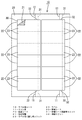
例えばA4サイズをなす矩形状の粘着シート20には粘着剤が全面にわたって塗布されて粘着剤層21が形成されている。この粘着剤層21の全域を覆うようにA4サイズの剥離シート30が粘着シート20に重ね合わされ、両者が一体となって一枚のラベル用シート10が構成されている。
【0028】
粘着シート20には、略矩形をなす複数のラベル用切り離しスリット22が、粘着シート20の長辺に沿って2列に並んで設けられている。このラベル用切り離しスリット22に囲まれて、複数のラベル23が、粘着シート20から切り離し可能に形成されている。
【0029】
剥離シート30には、その一方の短辺側の端縁から他方の短辺側の端縁にまで延びかつ長辺と平行に剥離シート剥離用スリット31が形成されており、この剥離シート剥離用スリット31は、ラベル切り離し用スリット22によって囲まれる各領域を連続的に横断するように、各列に一本ずつ形成されている。この剥離シート剥離用スリット31は、図1に示すように略矩形のラベル切り離し用スリット22によって囲まれた領域のうち、例えば右端寄りの位置を横断するように設けられている。
【0030】
粘着シート20及び剥離シート30には、ラベル切り離し用スリット22によって囲まれる領域以外の領域に、粘着シート20及び剥離シート30の短辺側の端縁からラベル切り離し用スリット22につながるように、ミシン目11(請求項1の切断可能線に相当)が形成されている。このミシン目11は剥離シート剥離用スリット31の左方に、剥離シート剥離用スリット31と同一方向を向いて平行に延びるように形成されている。
【0031】
剥離シート30には、ミシン目11とラベル切り離し用スリット22との交点から剥離シート剥離用スリット31まで、ラベル切り離し用スリット22と重なって補助スリット32が形成されている。
【0032】
次に、本実施形態のラベル用シート10の作用及び効果について説明する。
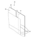
粘着シート20及び剥離シート30の一方の短辺に形成されたミシン目11の両側を指で摘んでミシン目11を開くようにして引っ張ると、粘着シート20及び剥離シート30はミシン目11に案内されて切断され、ラベル切り離し用スリット22まで切り開かれた状態になる。そして、ミシン目11とラベル切り離し用スリット22との交点から剥離シート剥離用スリット31までには、ラベル切り離し用スリット31と重なって補助スリット32が剥離シート30上に形成されているので、剥離シート30は、これらの短辺の端縁から剥離シート剥離用スリット31まで切り開かれた状態になる(図3参照)。
【0033】
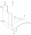
次いで、切り離したミシン目11の両側を指で摘んだまま、剥離シート剥離用スリット31に沿って剥離シート30を粘着シート20から剥がし取る方向に引っ張る。このとき、ミシン目11は剥離シート剥離用スリット31と同一方向を向いて形成されているので、ミシン目11を切り離す際に引っ張る方向とほぼ同一の方向に引っ張ればよい。すると剥離シート30の右側部分を、剥離シート剥離用スリット31に沿って、粘着シート20から剥がし取ることができる。このとき、粘着シート20にはラベル切り離し用スリット22が形成されているから、剥がし取られた剥離シート30に付着している粘着シート20はラベル23から切り離される。(図4参照)。この結果、ラベル23は、剥離シート30に付着したまま、粘着剤層21の一部が露出する状態となる。
【0034】
剥離シート20をさらに引っ張り、剥離シート剥離用スリット31に沿って剥離シート30を粘着シート20から剥がし取る。すると、ラベル用シート10に1列に並んで形成された複数のラベル23について、剥離シート剥離用スリット31に沿って剥離シート30を剥がし取ることができる。この結果、これらのラベル23は全て、剥離シート30に付着したまま、粘着剤層21の一部が露出する状態となる(図5参照)。
【0035】
これらのラベル23を例えば封筒等に貼り付ける場合には、粘着剤層21の一部を露出させたラベル23のうち、剥離シート30が残存している部分を持ちながら、露出した粘着剤層21を所要の箇所に貼り付ける。その後、ラベル切り離し用スリット22に沿ってラベル23を粘着シート20から切り離しながら、剥離シート30の残部をラベル23から剥離し、粘着剤層21を露出させ、所要の箇所にラベル23を貼り付ける。複数のラベル23について上記と同様の作業を繰り返すことにより、連続的にラベル23を貼り付けることができる。
【0036】
このように本実施形態では、ミシン目11を開くことにより、ラベルを剥がし取るきっかけを容易に作ることができる。また、剥がし取ったラベル23が不用意に他のものに張り付くことが防止される。
【0037】
また、ミシン目11と剥離シート剥離用スリット31とが同一方向を向いて延びるように形成されているので、ミシン目11を開く動作に引き続いて剥離シート30を剥がし取ることができる。
【0038】
さらに、例えば封筒等にラベルを貼り付ける際、ラベル一枚毎に剥離シートを剥がし取る場合に比べて、貼り付け作業を連続的に行うことができる。
【0039】
<第2実施形態>
次に、本発明の第2実施形態を図6ないし図8によって説明する。
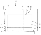
第1実施形態との相違は、粘着シート20及び剥離シート30に、ラベル切り離し用スリット22によって囲まれる領域以外の領域に、粘着シート20及び剥離シート30の短辺側の端縁から、ラベル切り離し用スリット22と剥離シート剥離用スリット31との交点の近傍にかけてミシン目11(請求項2の切断可能線に相当)が形成されているところにある。なお、このミシン目11はラベル切り離し用スリット22につながるように形成されている(図6参照)。
【0040】
また、第1実施形態においては補助スリット32が設けられているが、第2実施形態では設けられていない。
【0041】
この他は前記第1実施形態と同様であるので、前記第1実施形態と同一部分には同一符号を付して重複する説明を省略する。
【0042】
第2実施形態の作用及び効果を説明する。
粘着シート20及び剥離シート30の一方の短辺に形成されたミシン目11の両側を指で摘んでミシン目11を開くようにして引っ張ると、粘着シート20及び剥離シート30はミシン目11に案内されて切断され、ラベル切り離し用スリット22と剥離シート剥離用スリット31との交点の近傍まで切り開かれた状態になる(図7参照)。
【0043】
さらにラベル用シート10を引っ張ると、剥離シート30は剥離シート剥離用スリット31まで容易に破れて、剥離シート30の端縁から剥離シート剥離用スリット31まで切り開かれた状態になる。一方、粘着シート20は、ミシン目11がラベル切り離し用スリット22につながるように形成されていることから、粘着シート20の端縁からラベル切り離し用スリット22まで切り開かれた状態になっている(図8参照)。
【0044】
次いで、剥離シート剥離用スリット31に沿って、粘着シート20から剥離シート30を引き剥がす方向にラベル用シート10を引っ張ると、剥離シート30の右側部分は剥離シート剥離用スリット31に沿ってラベル23から剥がし取られて、ラベル23の粘着剤層21の一部が露出する。このとき、粘着シート20にはラベル切り離し用スリット22が形成されているから、剥がし取られた剥離シート30に付着している粘着シート20はラベル23から切り離される。
【0045】
このように、ラベル用シート10の端縁からラベル切り離し用スリット22と剥離シート剥離用スリット31との交点の近傍までミシン目11を形成するという簡易な手法により、ラベル23をラベル用シート10から剥がし取るきっかけを容易に作ることができる。
【0046】
なお、その他の作用及び効果については第1実施形態と同様であるため重複する説明を省略する。
【0047】
<第3実施形態>
上記した第1実施形態では、ミシン目11は剥離シート剥離用スリット31の左側に設けたが、本実施形態では、ミシン目11を剥離シート剥離用スリット31の右側に設けている(図9参照)。なお、その他の構造、作用及び効果については第1実施形態と同様であるため重複する説明を省略する(図10、図11参照)。
【0048】
<第4実施形態>
上記した第2実施形態では、ミシン目11は剥離シート剥離用スリット31の左側に設けたが、本実施形態では、ミシン目11を剥離シート剥離用スリット31の右側に設けている(図12参照)。なお、その他の構造、作用及び効果については第2実施形態と同様であるため重複する説明を省略する(図13、図14参照)。
【0049】
<第5実施形態>
上記した第2実施形態では、ミシン目11はラベル切り離し用スリット22につながるように形成されていたが、本実施形態では、ミシン目11が剥離シート剥離用スリット31につながるように設けられている。なお、このミシン目11は、剥離シート剥離用スリット31の左側に設けられていてもよいし(図15(A)参照)、右側に設けられていてもよい(図15(B)参照)。
【0050】
粘着シート20及び剥離シート30の一方の短辺に形成されたミシン目11の両側を指で摘んでミシン目11を開くようにして引っ張ると、粘着シート20及び剥離シート30はミシン目11に案内されて切断され、ラベル切り離し用スリット22と剥離シート剥離用スリット31との交点の近傍まで切り開かれた状態になる。
【0051】
さらにラベル用シート10を引っ張ると、粘着シート20はラベル切り離し用スリット22まで容易に破れて、粘着シート20の端縁からラベル切り離し用スリット22まで切り開かれた状態になる。一方、剥離シート30は、ミシン目11が剥離シート剥離用スリット31とつながるように形成されていることから、剥離シート30の端縁から剥離シート切り離し用スリット31まで切り開かれた状態になっている。
【0052】
次いで、剥離シート剥離用スリット31に沿って、粘着シート20から剥離シート30を引き剥がす方向にラベル用シート10を引っ張ると、剥離シート30の右側部分は剥離シート剥離用スリット31に沿ってラベル23から剥がし取られて、ラベル23の粘着剤層21の一部が露出する。このとき、粘着シート20にはラベル切り離し用スリット22が形成されているから、剥がし取られた剥離シート30に付着している粘着シート20はラベル23から切り離される。
【0053】
なお、その他の構造、作用及び効果は上記した第2実施形態と同様であるため重複する説明は省略する。
【0054】
<第6実施形態>
上記した第2実施形態では、ミシン目11は、粘着シート20及び剥離シート30の双方に設けられ、かつ剥離シート剥離用スリット31の左側に設けられていたが、本実施形態では、ミシン目11は、剥離シート剥離用スリット31の上に重なって、粘着シート20に設けられている(図16参照)。
【0055】
粘着シート20の一方の短辺に形成されたミシン目11の両側を指で摘んで、ミシン目11を切り開くようにして引っ張ると、粘着シート20はミシン目11に案内されて切断されるとともに、剥離シート剥離用スリット31に案内されてラベル切り離し用スリット22と剥離シート剥離用スリット31との交点まで切り開かれた状態になる。剥離シート30には剥離シート剥離用スリット31が形成されているので、剥離シート30はラベル切り離し用スリット22と剥離シート剥離用スリット31との交点まで切り開かれた状態になっている。
【0056】
次いで、剥離シート剥離用スリット31に沿って、粘着シート20から剥離シート30を引き剥がす方向にラベル用シート10を引っ張ると、剥離シート30の右側部分は剥離シート剥離用スリット31に沿ってラベル23から剥がし取られて、ラベル23の粘着剤層21の一部が露出する。このとき、粘着シート20にはラベル切り離し用スリット22が形成されているから、剥がし取られた剥離シート30に付着している粘着シート20はラベル23から切り離される。
【0057】
なお、その他の構造、作用及び効果は上記した第2実施形態と同様であるため重複する説明は省略する。
【0058】
<他の実施形態>
本発明は上記記述及び図面によって説明した実施形態に限定されるものではなく、例えば次のような実施形態も本発明の技術的範囲に含まれ、さらに、下記以外にも要旨を逸脱しない範囲内で種々変更して実施することができる。
【0059】
(1)ミシン目11は、剥離シート剥離用スリット31の左側に設けられていてもよいし、その右側に設けられていてもよい。
【0060】
(2)上記した実施形態では、ミシン目11は剥離シート剥離用スリット31と同一の方向を向いて延びるように形成されていたが、これに限られず、剥離シート剥離用スリット31と異なった方向を向いて延びるように形成されていても良い。
【図面の簡単な説明】
【図1】第1実施形態のラベル用シートの平面図
【図2】第1実施形態のラベル用シートの部分拡大平面図
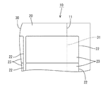
【図3】第1実施形態において、ミシン目を切り離した際のラベル用シートの部分拡大斜視図
【図4】第1実施形態において、剥離用シートを剥がし取る際のラベル用シートの部分拡大斜視図
【図5】第1実施形態において、剥離用シートを剥がし取った後のラベル用シートの平面図
【図6】第2実施形態のラベル用シートの部分拡大平面図
【図7】第2実施形態において、ミシン目を切り離した際のラベル用シートの部分拡大斜視図
【図8】第2実施形態において、剥離用シートを剥がし取る際のラベル用シートの部分拡大斜視図
【図9】第3実施形態のラベル用シートの部分拡大平面図
【図10】第3実施形態において、ミシン目を切り離した際のラベル用シートの部分拡大斜視図
【図11】第3実施形態において、剥離用シートを剥がし取る際のラベル用シートの部分拡大斜視図
【図12】第4実施形態のラベル用シートの部分拡大平面図
【図13】第4実施形態において、ミシン目を切り離した際のラベル用シートの部分拡大斜視図
【図14】第4実施形態において、剥離用シートを剥がし取る際のラベル用シートの部分拡大斜視図
【図15】第5実施形態のラベル用シートの部分拡大平面図
【図16】第6実施形態のラベル用シートの部分拡大平面図
【符号の説明】
10…ラベル用シート
11…ミシン目
20…粘着シート
21…粘着剤層
22…ラベル切り離し用スリット
23…ラベル
30…剥離シート
31…剥離シート剥離用スリット
32…補助スリット[0001]
BACKGROUND OF THE INVENTION
The present invention relates to a label sheet.
[0002]
[Prior art]
Conventionally, as a label sheet, a release sheet is overlapped so as to cover an adhesive layer of an adhesive sheet having an adhesive layer, and the adhesive sheet is formed with a slit capable of separating the label. (See Patent Document 1).
[0003]
To peel off the label from such a label sheet and attach it to, for example, an envelope, the label sheet is curved with the release sheet side inward in the vicinity of the label corner of the label sheet. The label was peeled off from the release sheet by picking up the corner of the label with a finger and pulling it.
[0004]
However, when trying to peel off the label as described above, the corner of the label is difficult to lift from the release sheet due to excessively strong adhesive or weak elasticity of the label. There are cases where it is difficult to create an opportunity to peel off the label.
[0005]
Further, when the label is peeled off from the release sheet in this way, a large amount of the adhesive adheres to the finger, and the peeled label may inadvertently stick to another.
[0006]
[Patent Document 1]
JP-A-9-48188 [0007]
[Problems to be solved by the invention]
This invention is completed based on the above situations, Comprising: It aims at providing the sheet | seat for labels which can make the opportunity to peel off a label from a peeling sheet easily.
[0008]
[Means for Solving the Problems]
As a means for achieving the above object, the invention of claim 1 is characterized in that a pressure-sensitive adhesive sheet having a pressure-sensitive adhesive layer is laminated so that the pressure-sensitive adhesive contacts the release sheet, In the label sheet in which a label separating slit for use by separating and sticking to a required place is formed, the release sheet extends from the edge to the inside of the region surrounded by the label separating slit. In a region other than the region surrounded by the label separation slit, a release sheet separation slit is formed, and the adhesive sheet and the release sheet are cut to connect their edge and the label separation slit. An auxiliary slit is formed on the release sheet so as to connect the cuttable line and the release sheet release slit. Wherein the bets are formed.
[0009]
The invention of claim 2 is a pressure-sensitive adhesive sheet having a pressure-sensitive adhesive layer that is stacked so that the pressure-sensitive adhesive contacts the release sheet, and a part of the pressure-sensitive adhesive sheet is cut off and pasted to a required location. In the label sheet in which a slit for separating the label for forming is formed, the release sheet is formed with a slit for separating the release sheet from the edge thereof to the inside of the region surrounded by the slit for separating the label, In the region other than the region surrounded by the label separation slit, the adhesive sheet and the release sheet can be cut from their edge to the vicinity of the intersection of the label separation slit and the release sheet separation slit. A line is formed.
[0010]
A third aspect of the present invention is the label sheet according to the first or second aspect, wherein the cuttable line is formed to extend in the same direction as the release sheet peeling slit.
[0011]
According to a fourth aspect of the present invention, in the label sheet according to any one of the first to third aspects, a plurality of the label separation slits are formed side by side on the pressure-sensitive adhesive sheet, and the release sheet peeling slit is the label separation slit. It is characterized by being formed from one edge of the release sheet to the other edge so as to continuously cross a plurality of regions surrounded by.
[0012]
[Action and effect of the invention]
<Invention of Claim 1>
According to the present invention, by holding both sides of the adhesive sheet and formed in the release sheet is cleavable line with a finger, pulling the label sheet to open a cleavable line, pressure-sensitive adhesive sheet and a release sheet cutting Break along possible lines.
[0013]
Since this cuttable line is formed so as to connect the edge of the adhesive sheet and the release sheet and the slit for separating the label, the adhesive sheet and the release sheet are cut from the edge to the slit for separating the label. .
[0014]
Then, since the auxiliary sheet which connects the cuttable line and the release sheet peeling slit is formed in the release sheet, the adhesive sheet and the release sheet are opened from the edge to the release sheet release slit. .
[0015]
Next, when the label sheet is pulled in the direction of peeling the release sheet from the adhesive sheet along the release sheet peeling slit, the release sheet is easily peeled off from the label along the release sheet peeling slit. Only a part of the adhesive layer is exposed.
[0016]
Thus, the exposed adhesive layer is affixed on a required location, holding the part with the peeling sheet remaining among the labels which exposed a part of adhesive layer in this way. Then, while separating the label from the pressure-sensitive adhesive sheet along the label separation slit, the remaining part of the release sheet is peeled off from the label, the pressure-sensitive adhesive layer is exposed, and the label is attached to a required location.
[0017]
According to the first aspect of the present invention, as described above, an opportunity to peel off the label from the release sheet can be easily made. It is also possible to prevent the peeled label from sticking to other things carelessly.
[0018]
<Invention of Claim 2>
According to the invention of claim 2, by pulling the sides of the pressure-sensitive adhesive sheet and formed in the release sheet is cleavable line with a finger, pulling the label sheet to open a cleavable line, pressure-sensitive adhesive sheet and a release sheet cutting Break along possible lines.
[0019]
Since this severable line extends from the edge of the adhesive sheet and the release sheet to the vicinity of the intersection of the slit for separating the label and the release sheet peeling slit, the adhesive sheet and the release sheet are separated from the edges of the adhesive sheet and the release sheet. It will be in the state opened and cut to the vicinity of the intersection of the slit for peeling and the slit for peeling sheet peeling.
[0020]
When the label sheet is further pulled, the release sheet is easily torn to the release sheet release slit, and is cut from the edge of the release sheet to the release sheet release slit. On the other hand, the pressure-sensitive adhesive sheet is easily torn up to the label separation slit, and is cut from the edge of the pressure-sensitive adhesive sheet to the label separation slit.
[0021]
Next, when the label sheet is pulled in the direction of peeling the release sheet from the adhesive sheet along the release sheet peeling slit, the release sheet is easily peeled off from the label along the release sheet peeling slit. Only a part of the adhesive layer is exposed.
[0022]
Thus, the exposed adhesive layer is affixed on a required location, holding the part with the peeling sheet remaining among the labels which exposed a part of adhesive layer in this way. Then, while separating the label from the pressure-sensitive adhesive sheet along the label separation slit, the remaining part of the release sheet is peeled off from the label, the pressure-sensitive adhesive layer is exposed, and the label is attached to a required location.
[0023]
As described above, according to the invention of claim 2, it is simple to form the cuttable line so as to extend from the edge of the adhesive sheet and the release sheet to the vicinity of the intersection between the slit for separating the label and the slit for peeling the release sheet. By this method, it is possible to easily create an opportunity to peel off the label from the label sheet.
[0024]
<Invention of Claim 3>
According to the invention of claim 3, since the severable line is formed so as to extend in the same direction as the release sheet peeling slit, the both sides of the severable line are picked with fingers to open the severable line. After the adhesive sheet and the release sheet are cut by pulling the label sheet, the release sheet can be peeled off from the label along the release sheet release slit by applying force in the same direction as it is.
[0025]
<Invention of Claim 4>
According to invention of Claim 4, the slit for peeling sheet peeling is formed so that the area | region enclosed by the slit for label separation may be continuously traversed. For this reason, after tearing the adhesive sheet and release sheet guided by the cuttable line, peel off the release sheet along the release sheet release slit for multiple labels that are provided across the release sheet release slit. Can be taken.
[0026]
Accordingly, for example, when a label is attached to an envelope or the like, the attaching operation can be continuously performed as compared with the case where the release sheet is peeled off for each label.
[0027]
DETAILED DESCRIPTION OF THE INVENTION
Hereinafter, embodiments of the present invention will be described with reference to the accompanying drawings.
<First Embodiment>
A first embodiment of the present invention will be described with reference to FIGS.
First, the configuration of the
For example, a pressure-sensitive adhesive is applied over the entire surface of a rectangular pressure-
[0028]
The
[0029]
The
[0030]
The
[0031]
In the
[0032]
Next, the operation and effect of the
When both sides of the
[0033]
Next, the
[0034]
The
[0035]
When these
[0036]
As described above, in the present embodiment, by opening the
[0037]
Further, since the
[0038]
Further, for example, when a label is attached to an envelope or the like, the attaching operation can be continuously performed as compared with the case where the release sheet is peeled off for each label.
[0039]
Second Embodiment
Next, a second embodiment of the present invention will be described with reference to FIGS.
The difference from the first embodiment is that the pressure-
[0040]
Further, although the auxiliary slit 32 is provided in the first embodiment, it is not provided in the second embodiment.
[0041]
Since the other parts are the same as those in the first embodiment, the same parts as those in the first embodiment are denoted by the same reference numerals, and redundant description is omitted.
[0042]
The operation and effect of the second embodiment will be described.
When both sides of the
[0043]
When the
[0044]
Next, when the
[0045]
Thus, the
[0046]
Since other operations and effects are the same as those in the first embodiment, a duplicate description is omitted.
[0047]
<Third Embodiment>
In the first embodiment described above, the
[0048]
<Fourth embodiment>
In the second embodiment described above, the
[0049]
<Fifth Embodiment>
In the above-described second embodiment, the
[0050]
When both sides of the
[0051]
When the
[0052]
Next, when the
[0053]
Since other structures, operations, and effects are the same as those of the second embodiment described above, a duplicate description is omitted.
[0054]
<Sixth Embodiment>
In the above-described second embodiment, the
[0055]
When both sides of the
[0056]
Next, when the
[0057]
Since other structures, operations, and effects are the same as those of the second embodiment described above, a duplicate description is omitted.
[0058]
<Other embodiments>
The present invention is not limited to the embodiments described with reference to the above description and drawings. For example, the following embodiments are also included in the technical scope of the present invention, and further, within the scope not departing from the gist of the invention other than the following. Various modifications can be made.
[0059]
(1) The
[0060]
(2) In the above-described embodiment, the
[Brief description of the drawings]
FIG. 1 is a plan view of a label sheet of the first embodiment. FIG. 2 is a partially enlarged plan view of the label sheet of the first embodiment. FIG. 3 is a label when a perforation is cut off in the first embodiment. FIG. 4 is a partially enlarged perspective view of a label sheet when the peeling sheet is peeled off in the first embodiment. FIG. 5 is a peeling view of the peeling sheet in the first embodiment. FIG. 6 is a partially enlarged plan view of the label sheet of the second embodiment. FIG. 7 is a partially enlarged perspective view of the label sheet when the perforation is cut off in the second embodiment. FIG. 8 is a partially enlarged perspective view of the label sheet when the peeling sheet is peeled off in the second embodiment. FIG. 9 is a partially enlarged plan view of the label sheet in the third embodiment. In form, perforation FIG. 11 is a partially enlarged perspective view of the label sheet when peeled off in the third embodiment. FIG. 12 is a partially enlarged perspective view of the label sheet when the peeling sheet is peeled off in the third embodiment. FIG. 13 is a partially enlarged perspective view of the label sheet when the perforation is cut off in the fourth embodiment. FIG. 14 is for labeling when the peeling sheet is peeled off in the fourth embodiment. FIG. 15 is a partially enlarged plan view of a label sheet according to a fifth embodiment. FIG. 16 is a partially enlarged plan view of a label sheet according to a sixth embodiment.
DESCRIPTION OF
Claims (4)
前記剥離シートには、その端縁から前記ラベル切り離し用スリットに囲まれた領域の内部にかけて剥離シート剥離用スリットが形成されており、
前記ラベル切り離し用スリットによって囲まれた領域以外の領域において、前記粘着シート及び前記剥離シートには、それらの端縁と前記ラベル切り離し用スリットとをつなぐ切断可能線が形成され、前記剥離シートには、前記切断可能線と前記剥離シート剥離用スリットとをつなぐように補助スリットが形成されていることを特徴とするラベル用シート。A label separating slit for use by overlapping an adhesive sheet having an adhesive layer so that the adhesive is in contact with the release sheet, and separating and pasting a part of the adhesive sheet to a required location. In the label sheet in which is formed,
In the release sheet, a release sheet peeling slit is formed from the edge of the release sheet to the inside of the region surrounded by the label separating slit,
In a region other than the region surrounded by the label separation slit, the adhesive sheet and the release sheet are formed with a breakable line connecting the edge and the label separation slit, and the release sheet An auxiliary slit is formed so as to connect the cuttable line and the release sheet peeling slit.
前記剥離シートには、その端縁から前記ラベル切り離し用スリットに囲まれた領域の内部にかけて剥離シート剥離用スリットが形成されており、
前記ラベル切り離し用スリットによって囲まれた領域以外の領域において、前記粘着シート及び前記剥離シートには、それらの端縁から前記ラベル切り離し用スリットと剥離シート剥離用スリットとの交点の近傍にかけて延びる切断可能線が形成されていることを特徴とするラベル用シート。A label separating slit for use by overlapping an adhesive sheet having an adhesive layer so that the adhesive is in contact with the release sheet, and separating and pasting a part of the adhesive sheet to a required location. In the label sheet in which is formed,
In the release sheet, a release sheet peeling slit is formed from the edge of the release sheet to the inside of the region surrounded by the label separating slit,
In the region other than the region surrounded by the label separation slit, the adhesive sheet and the release sheet can be cut from their edge to the vicinity of the intersection of the label separation slit and the release sheet separation slit. A label sheet, characterized in that a line is formed.
Priority Applications (1)
| Application Number | Priority Date | Filing Date | Title |
|---|---|---|---|
| JP2003149234A JP3773503B2 (en) | 2003-05-27 | 2003-05-27 | Label sheet |
Applications Claiming Priority (1)
| Application Number | Priority Date | Filing Date | Title |
|---|---|---|---|
| JP2003149234A JP3773503B2 (en) | 2003-05-27 | 2003-05-27 | Label sheet |
Publications (3)
| Publication Number | Publication Date |
|---|---|
| JP2004354474A JP2004354474A (en) | 2004-12-16 |
| JP2004354474A5 JP2004354474A5 (en) | 2005-09-15 |
| JP3773503B2 true JP3773503B2 (en) | 2006-05-10 |
Family
ID=34045402
Family Applications (1)
| Application Number | Title | Priority Date | Filing Date |
|---|---|---|---|
| JP2003149234A Expired - Lifetime JP3773503B2 (en) | 2003-05-27 | 2003-05-27 | Label sheet |
Country Status (1)
| Country | Link |
|---|---|
| JP (1) | JP3773503B2 (en) |
Families Citing this family (7)
| Publication number | Priority date | Publication date | Assignee | Title |
|---|---|---|---|---|
| JP4730665B2 (en) * | 2006-04-28 | 2011-07-20 | 株式会社Kalbas | Label sheet |
| JP5141263B2 (en) * | 2008-01-23 | 2013-02-13 | 大日本印刷株式会社 | IC tag label |
| MX2010011656A (en) * | 2008-04-24 | 2010-11-30 | Avery Dennison Corp | Sheet having removable labels and related method. |
| JP5426981B2 (en) * | 2009-09-25 | 2014-02-26 | パナソニック株式会社 | Label with mount |
| JP2013011807A (en) * | 2011-06-30 | 2013-01-17 | Three M Innovative Properties Co | Label sheet |
| JP5951264B2 (en) * | 2012-01-24 | 2016-07-13 | コクヨ株式会社 | Sheet body |
| JP6053340B2 (en) * | 2012-06-12 | 2016-12-27 | キヤノン株式会社 | Sticker recording paper |
-
2003
- 2003-05-27 JP JP2003149234A patent/JP3773503B2/en not_active Expired - Lifetime
Also Published As
| Publication number | Publication date |
|---|---|
| JP2004354474A (en) | 2004-12-16 |
Similar Documents
| Publication | Publication Date | Title |
|---|---|---|
| US20060147668A1 (en) | Label sheet | |
| JP2007193164A (en) | Label with mount | |
| JP4785050B2 (en) | Label sheet | |
| EP0213812B1 (en) | A label | |
| JP4781293B2 (en) | Label sheet | |
| JP3773503B2 (en) | Label sheet | |
| JP4197697B2 (en) | Label sheet | |
| JP4730665B2 (en) | Label sheet | |
| JP4883781B2 (en) | Label sheet | |
| JP6276515B2 (en) | Peel detection label | |
| JP5426981B2 (en) | Label with mount | |
| JP2009069936A (en) | Rfid label | |
| JPH09240660A (en) | Box | |
| JP5592149B2 (en) | Separation sheet | |
| JP2000284695A (en) | Label sheet | |
| JP7160542B2 (en) | sheet laminate | |
| JP5409453B2 (en) | label | |
| JPH0454104Y2 (en) | ||
| JP2011189681A (en) | Sheet for print | |
| JP2009276474A (en) | Pressure-sensitive adhesive label with release paper | |
| JP4630170B2 (en) | Separation sheet for printing | |
| JP2010032708A (en) | Seal label | |
| JP2520847B2 (en) | Bag opening device | |
| JP6568728B2 (en) | Pseudo adhesive sheet | |
| JP3087676U (en) | Easily detachable film seal |
Legal Events
| Date | Code | Title | Description |
|---|---|---|---|
| A521 | Request for written amendment filed |
Free format text: JAPANESE INTERMEDIATE CODE: A523 Effective date: 20050330 |
|
| A621 | Written request for application examination |
Free format text: JAPANESE INTERMEDIATE CODE: A621 Effective date: 20050330 |
|
| A871 | Explanation of circumstances concerning accelerated examination |
Free format text: JAPANESE INTERMEDIATE CODE: A871 Effective date: 20050330 |
|
| A975 | Report on accelerated examination |
Free format text: JAPANESE INTERMEDIATE CODE: A971005 Effective date: 20050419 |
|
| A131 | Notification of reasons for refusal |
Free format text: JAPANESE INTERMEDIATE CODE: A131 Effective date: 20050712 |
|
| A521 | Request for written amendment filed |
Free format text: JAPANESE INTERMEDIATE CODE: A523 Effective date: 20050909 |
|
| A131 | Notification of reasons for refusal |
Free format text: JAPANESE INTERMEDIATE CODE: A131 Effective date: 20051025 |
|
| A521 | Request for written amendment filed |
Free format text: JAPANESE INTERMEDIATE CODE: A523 Effective date: 20051226 |
|
| TRDD | Decision of grant or rejection written | ||
| A01 | Written decision to grant a patent or to grant a registration (utility model) |
Free format text: JAPANESE INTERMEDIATE CODE: A01 Effective date: 20060117 |
|
| A61 | First payment of annual fees (during grant procedure) |
Free format text: JAPANESE INTERMEDIATE CODE: A61 Effective date: 20060214 |
|
| R150 | Certificate of patent or registration of utility model |
Ref document number: 3773503 Country of ref document: JP Free format text: JAPANESE INTERMEDIATE CODE: R150 Free format text: JAPANESE INTERMEDIATE CODE: R150 |
|
| FPAY | Renewal fee payment (event date is renewal date of database) |
Free format text: PAYMENT UNTIL: 20090224 Year of fee payment: 3 |
|
| FPAY | Renewal fee payment (event date is renewal date of database) |
Free format text: PAYMENT UNTIL: 20100224 Year of fee payment: 4 |
|
| R250 | Receipt of annual fees |
Free format text: JAPANESE INTERMEDIATE CODE: R250 |
|
| FPAY | Renewal fee payment (event date is renewal date of database) |
Free format text: PAYMENT UNTIL: 20100224 Year of fee payment: 4 |
|
| FPAY | Renewal fee payment (event date is renewal date of database) |
Free format text: PAYMENT UNTIL: 20110224 Year of fee payment: 5 |
|
| R250 | Receipt of annual fees |
Free format text: JAPANESE INTERMEDIATE CODE: R250 |
|
| FPAY | Renewal fee payment (event date is renewal date of database) |
Free format text: PAYMENT UNTIL: 20110224 Year of fee payment: 5 |
|
| FPAY | Renewal fee payment (event date is renewal date of database) |
Free format text: PAYMENT UNTIL: 20120224 Year of fee payment: 6 |
|
| R250 | Receipt of annual fees |
Free format text: JAPANESE INTERMEDIATE CODE: R250 |
|
| FPAY | Renewal fee payment (event date is renewal date of database) |
Free format text: PAYMENT UNTIL: 20120224 Year of fee payment: 6 |
|
| FPAY | Renewal fee payment (event date is renewal date of database) |
Free format text: PAYMENT UNTIL: 20130224 Year of fee payment: 7 |
|
| R250 | Receipt of annual fees |
Free format text: JAPANESE INTERMEDIATE CODE: R250 |
|
| FPAY | Renewal fee payment (event date is renewal date of database) |
Free format text: PAYMENT UNTIL: 20130224 Year of fee payment: 7 |
|
| FPAY | Renewal fee payment (event date is renewal date of database) |
Free format text: PAYMENT UNTIL: 20130224 Year of fee payment: 7 |
|
| FPAY | Renewal fee payment (event date is renewal date of database) |
Free format text: PAYMENT UNTIL: 20140224 Year of fee payment: 8 |
|
| R250 | Receipt of annual fees |
Free format text: JAPANESE INTERMEDIATE CODE: R250 |
|
| R250 | Receipt of annual fees |
Free format text: JAPANESE INTERMEDIATE CODE: R250 |
|
| R250 | Receipt of annual fees |
Free format text: JAPANESE INTERMEDIATE CODE: R250 |
|
| R250 | Receipt of annual fees |
Free format text: JAPANESE INTERMEDIATE CODE: R250 |
|
| R250 | Receipt of annual fees |
Free format text: JAPANESE INTERMEDIATE CODE: R250 |
|
| R250 | Receipt of annual fees |
Free format text: JAPANESE INTERMEDIATE CODE: R250 |
|
| R250 | Receipt of annual fees |
Free format text: JAPANESE INTERMEDIATE CODE: R250 |
|
| R250 | Receipt of annual fees |
Free format text: JAPANESE INTERMEDIATE CODE: R250 |
|
| R250 | Receipt of annual fees |
Free format text: JAPANESE INTERMEDIATE CODE: R250 |
|
| R250 | Receipt of annual fees |
Free format text: JAPANESE INTERMEDIATE CODE: R250 |
|
| R250 | Receipt of annual fees |
Free format text: JAPANESE INTERMEDIATE CODE: R250 |
|
| EXPY | Cancellation because of completion of term |