JP3772669B2 - Coating device and coating method - Google Patents
Coating device and coating method Download PDFInfo
- Publication number
- JP3772669B2 JP3772669B2 JP2000375444A JP2000375444A JP3772669B2 JP 3772669 B2 JP3772669 B2 JP 3772669B2 JP 2000375444 A JP2000375444 A JP 2000375444A JP 2000375444 A JP2000375444 A JP 2000375444A JP 3772669 B2 JP3772669 B2 JP 3772669B2
- Authority
- JP
- Japan
- Prior art keywords
- support
- gravure roll
- paint
- coating
- contact
- Prior art date
- Legal status (The legal status is an assumption and is not a legal conclusion. Google has not performed a legal analysis and makes no representation as to the accuracy of the status listed.)
- Expired - Fee Related
Links
Images
Landscapes
- Application Of Or Painting With Fluid Materials (AREA)
- Coating Apparatus (AREA)
- Manufacturing Of Magnetic Record Carriers (AREA)
Description
【0001】
【発明の属する技術分野】
本発明は、塗料の塗布装置及び塗布方法に係り、特に、磁気テープなどの磁気記録媒体を製造する際に適用して好適な塗料の塗布装置及び塗布方法に関する。
【0002】
【従来の技術】
一般に、オーディオテープやビデオテープ、バックアップ用データカートリッジ等においては、ポリエチレンテレフタレート等の非磁性からなる支持体上に、強磁性粉末や結合剤、分散剤、潤滑剤等を有機溶媒に分散混練してなる磁性塗料を塗布することで磁性層が形成されている。このような磁性塗料を支持体上に安定して塗布する方式としては、高速作業性に優れ、操作や管理が容易で生産コストが安価であるという観点から、これまでグラビア塗布方式が多用されている。
【0003】
グラビア塗布方式は、ロール外周面にグラビア彫刻が施されたグラビアロールを用いて支持体に塗料を塗布するものである。また、グラビア塗布方式の中には、支持体の走行方向に対してグラビアロールを反対方向に回転させるリバースロール塗布方式と呼ばれるものがある。このリバースロール塗布方式によれば、高速生産性を実現したうえで、塗料塗布後の平滑処理(スムージング処理)を行わなくても平坦な塗膜を得ることができる。リバースロール塗布方式は、大きくはキスリバース塗布方式とミニキスリバース塗布方式に大別される。キスリバース塗布方式とミニキスリバース方式とは、使用するグラビアロールの径が異なるだけで、基本的な塗布の原理は同様である。以下、キスリバース塗布方式を採用した従来の塗布装置の構成について説明する。
【0004】
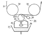
図9は従来の塗布装置の構成例を示す概略側面図である。図において、支持体31は、2つのガイドロール32によって支持されている。2つのガイドロール32の間にはグラビアロール33が配設されている。グラビアロール33は、その外周面にセルパターン33Pが刻設された金属ロールからなるもので、図中矢印方向(反時計回り方向)に回転可能に支持されている。グラビアロール33の上側周面は支持体31に圧接する状態に配置されている。
【0005】
また、グラビアロール33の近傍には塗料供給器34が配設されている。塗料供給器34は、塗料供給貯溜器35、ドクターブレード摺接装置36及び受け皿37等を備えて構成されている。塗料供給貯溜器35には塗料供給貯溜路38が設けられ、この塗料供給貯溜路38からグラビアロール33に塗料が供給されるようになっている。ドクターブレード摺接装置36は、グラビアロール33に供給された余剰の塗料を掻き落とすことで、ロール外周面上のセルパターン33Pへの塗料の充填及び計量を行うものである。受け皿37は、ドクターブレード摺接装置36によって掻き落とされた塗料を回収するものである。
【0006】
上記構成からなる塗布装置においては、2つのガイドロール32に支持された支持体31が矢印方向に走行し、この走行中の支持体31の下面にグラビアロール33が接触した状態となる。このとき、塗料供給器34でグラビアロール33の外周面(セルパターン)上に供給された塗料は、ドクターブレード摺接装置36によって余剰分を掻き落とされた後、支持体31との接触位置で当該支持体31の下面に塗布(転写)される。
【0007】
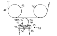
図10は従来の塗布装置の他の構成例を示す概略側面図である。図示した塗布装置においては、支持体41が2つのガイドロール42によって支持されており、この点は先述の塗布装置と同様である。ただし、グラビアロール43は、その外周部(頂部)を支持体41に略線状に接触(略線接触)した状態で支持されている。グラビアロール43の外周面には上記同様にセルパターン43Pが刻設されている。また、塗料供給器44は、塗料供給ブロック45、計量用ドクターブレード46及びシール用ドクターブレード47を備えて構成されている。塗料供給ブロック45内には、塗料供給路48と塗料排出路49が形成されている。さらに、塗料供給路48と塗料排出路49を繋ぐ空間部分には堰盤50が組み込まれている。
【0008】
上記構成からなる塗布装置においては、2つのガイドロール42に支持された支持体41が矢印方向に走行し、この走行中の支持体41の下面にグラビアロール43が略線接触(キスタッチ)した状態となる。一方、塗料供給器44においては、塗料供給路48を通して供給された塗料が堰盤49によって貯溜され、この貯溜された塗料がグラビアロール43の外周面に保持(ピックアップ)される。こうしてグラビアロール43に保持された塗料の余剰分は、グラビアロール43の回転にしたがって計量ドクターブレード46で掻き落とされた後、塗料排出路49を通して排出される。これに対して、計量ドクターブレード46でグラビアロール43外周面のセルパターンに充填された塗料は、グラビアロール43の回転にしたがって支持体41との接触位置へと移送され、そこで支持体41の下面に塗布(転写)される。
【0009】
【発明が解決しようとする課題】
ところで、上記図9に示す従来の塗布装置においては、2つのガイドロール32の間で支持体31にグラビアロール33を押し付けて両者を接触(圧接)させるようにしている。そのため、グラビアロール33に対する支持体31の抱き角度(巻き付き角度)が大きくなり、これに伴ってグラビアロール33と支持体31との接触面積も広くなる。そうした場合、グラビアロール33と支持体31との接触部分に形成される塗料の溜まり(以下、転写ビード)が、支持体31の走行方向に沿って幅広に形成されるため、塗膜厚を精度良く制御することが困難となる。
【0010】
これに対して、上記図10に示す従来の塗布装置においては、グラビアロール43に対する支持体41の抱き角度(巻き付き角度)をほぼゼロとしているため、グラビアロール43と支持体41との接触面積が狭くなる。そのため、グラビアロール43と支持体41との接触部分に形成される転写ビードも狭くなり、これによって塗料の塗布量制御をより精密に行うことが可能となる。その結果、塗膜厚の精度が安定し、薄膜層の形成が容易になる。
【0011】
ただし、図10に示す塗布装置では、転写ビードが支持体41の走行方向に広がるため、塗布速度の高速化への対応としてグラビアロール41の回転速度を速めると、塗料の乱れや泳ぎによる被れ等が生じやすくなる。また、高速塗布に転写ビードが耐え切れなくなって塗料の飛散が発生する場合もある。こうした高速塗布による不具合は、先の図9に示す塗布装置においても同様に生じる。また、転写ビードを安定させるために支持体41の張力を高くすると、支持体41の歪みストレスや塗布位置での細かい張力格差によってシワやムラ、さらには表面粗れがなどが発生しやすくなる。そのため、良質な塗膜を形成することが困難になる。
【0012】
本発明は、上記課題を解決するためになされたもので、その目的とするところは、塗布速度の高速化に適切に対応することができる塗料の塗布装置及び塗布方法を提供することにある。
【0013】
【課題を解決するための手段】
本発明に係る塗料の塗布装置は、駆動手段によって一方向に連続的に走行する支持体と、この支持体の走行方向と直交する向きで水平に配設されたグラビアロールとを備え、走行する支持体に対し、回転するグラビアロールを接触させて塗料を塗布するもので、駆動手段は、支持体を略垂直姿勢に支持するガイド部材を有するとともに、このガイド部材によって略垂直姿勢に支持された支持体を垂直方向に沿って下から上に移動するように走行し、グラビアロールは、当該グラビアロールに対する支持体の巻き付き角度がほぼゼロとなるように、ガイド部材によって略垂直姿勢に支持された支持体に水平方向から略線接触する状態で配置されるとともに、支持体との接触位置でロール外周部が支持体の走行方向と反対方向となる下向きに移動するように回転することにより、当該支持体との接触位置に塗料による楔形のビードを形成する構成を採用している。
【0014】
この塗料の塗布装置においては、ガイド部材によって支持体を略垂直姿勢に支持し、この支持体にグラビアロールを略線接触させるとともに、その接触位置でロール外周部が下向きに移動するようにグラビアロールを回転させることにより、グラビアロールと支持体との接触部分に幅狭の転写ビードが形成されかつその転写ビードが重力によって安定的に保持されるようになる。
【0015】
また本発明に係る塗料の塗布方法は、一方向に走行する支持体と、この支持体の走行方向と直交する向きで水平に配設されたグラビアロールとを用いて、走行する支持体に対し、回転するグラビアロールを接触させて塗料を塗布するもので、支持体を所定の位置で略垂直姿勢に支持しつつ垂直方向に沿って下から上に移動するように走行させるとともに、支持体との接触位置でロール外周部が支持体の走行方向と反対方向となる下向きに移動するようにグラビアロールを回転させ、この回転するグラビアロールを、当該グラビアロールに対する支持体の巻き付き角度がほぼゼロとなるように、所定の位置で支持体に水平方向から略線接触させることにより、当該接触位置に塗料による楔形のビードを形成する方法を採用している。
【0016】
この塗料の塗布方法においては、支持体を所定の位置で略垂直姿勢に支持し、この支持体にグラビアロールを略線接触させるとともに、その接触位置でロール外周部が下向きに移動するようにグラビアロールを回転させることにより、グラビアロールと支持体との接触部分に幅狭の転写ビードが形成されかつその転写ビードが重力によって安定的に保持されるようになる。
【0017】
【発明の実施の形態】
以下、本発明の実施の形態について図面を参照しつつ詳細に説明する。
【0018】
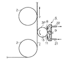
図1は本発明の実施形態に係る塗料の塗布装置の構成を示す側面概略図である。図1において、被塗布媒体となる支持体1は、例えば長尺状の樹脂フィルムからなるもので、図示しない繰り出し機から繰り出されて所定の経路を走行した後、図示しない巻き取り機に巻き取られるようになっている。支持体1としては、例えば磁気テープ、さらに具体的にはビデオテープやオーディオテープなどの磁気記録媒体のベースフィルムが一例として挙げられ、その要求特性から一般的にはポリエチレンテレフタレートの樹脂フィルムが用いられる。
【0019】
支持体1は、上記繰り出し機から巻き取り機へと至る走行経路の途中で2つのガイドロール2により支持されている。この支持状態において、支持体1は、上記繰り出し機及び巻き取り機の回転駆動と、これに伴う各々のガイドロール2の回転動作によってY方向に案内されて走行するようになっている。
【0020】
2つのガイドロール2は、適度な間隔をおいて上下に対向する状態で配置されている。このうち、下側のガイドロール2には略90°の角度をもって支持体1が巻き付けられている。また、上側のガイドロール2には線接触の状態で支持体1が接触している。これにより、支持体1の姿勢は下側のガイドロール2を境に水平状態から垂直状態に変移し、その垂直姿勢に支持されながら2つのガイドロール2の間を垂直方向に沿って下から上に移動するようになっている。
【0021】
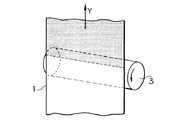
また、2つのガイドロール2の間(中間部)には、図2にも示すように支持体1の走行方向と直交する向きでグラビアロール3が水平に配設されている。このグラビアロール3は、例えばスチール等の金属によって構成されるもので、その外周面には微細な凹凸によるセルパターン(例えば亀甲型、格子型など)3Pが刻設されている。グラビアロール3は、図示しない回転手段によって図の矢印方向(反時計回り方向)に回転可能に設けられている。
【0022】
また、2つのガイドロール2の間では、当該2つのガイドロール2によって略垂直姿勢で支持された支持体1に対し、グラビアロール3が水平方向(横方向)から略線接触する状態で配置されている。さらに、グラビアロール3の回転方向は、支持体1との接触位置でロール外周部が下向きに移動しかつ支持体1の走行方向と反対方向となるように設定されている。
【0023】
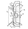
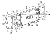
グラビアロール3の近傍には、支持体1との接触位置の反対側に位置して塗料供給器4が配設されている。図3は塗料供給器4の構成を示す側断面図であり、図4はその分解斜視図である。図示のように塗料供給器4は、上側ブロック5、中間ブロック6及び下側ブロック7を有している。上側ブロック5には計量用ドクターブレード8が装着されている。中間ブロック6には堰盤9と支持シャフト10が組み込まれている。下側ブロック7にはシール用ドクターブレード11が装着されている。
【0024】
計量用ドクターブレード8及びシール用ドクターブレード11は、それぞれグラビアロール3のほぼ全長(全幅)に差し渡すかたちで、当該グラビアロール3の軸方向に沿う長方形をなしている。これらのドクターブレード8,11は、例えばステンレス鋼(SUS材)によって構成されるもので、そのブレード本体部の厚さが0.15mm〜0.2mmで、ブレード先端部の厚さが0.08mm〜0.09mm、ブレード先端部の長さが1.3mm〜1.5mmに設定されている。また、各々のドクターブレード8,11の先端部は所定の角度α(好ましくはα=30°〜40°)をもってグラビアロール3の外周面に摺接するように配置されている。
【0025】
堰盤9は、グラビアロール3に供給すべき塗料12を貯溜する貯溜部13を形成するものである。この貯溜部13に貯溜される塗料12としては、非磁性塗料や磁性塗料など種々のものを適用することができる。また、磁気テープ等の磁気記録媒体を製造するにあたっては磁性塗料が用いられる。堰盤9のグラビアロール3と対向する側の面は、グラビアロール3の回転方向(矢印で示す)において順次グラビアロール3の外周面に近接する傾斜面とされ、この傾斜面の頂部に堰が形成されることで貯溜部13が形成されるようになっている。ちなみに、堰盤9の傾斜面の勾配角θは60°〜85°に設定することが好ましく、また堰の幅すなわちグラビアロール3に最接近する部分の尖端幅wは、0.5mm〜3.0mmに設定することが好ましい。
【0026】
また、上側ブロック5、中間ブロック6及び下側ブロック7は、それぞれ閉塞ブロック14にネジ止め等によって連結されることで、機械的に一体化されたブロック構体をなしている。このブロック構体の両端部には、それぞれサイドシールウォール15がネジ止め等によって装着されるようになっている。サイドシールウォール15は、例えば図示の如くホルダー部材16とサイドシール17によって構成されるもので、ブロック構体の両端部を閉塞する状態で装着される。
【0027】
ホルダー部材16は、金属等の剛体によって構成されるもので、所定の導電性を有している。サイドシール17は、例えば発泡ポリウレタン、発泡ポリエチレン等からなるもので、グラビアロール3の外周面に対応する湾曲面17Aを有している。このサイドシール17はネジ止め等によってホルダー部材16に取り付けられている。また、これらホルダー部材16及びサイドシール17の導電性は、例えばこれらホルダー部材16及びサイドシール17とグラビアロール3との間の抵抗が108Ω以下となる程度に設定されている。
【0028】
こうした構成により、塗料供給器4の内部には遮蔽空間18が形成されている。この遮蔽空間18は、上記ブロック構体によって形成される空間部を、前述した計量用ドクターブレード8、シール用ドクターブレード11及びサイドシールウォール15によって閉塞することにより形成されるものである。これにより塗料供給器4は密閉化された構造となっている。
【0029】
遮蔽空間18には堰盤9の傾斜面が面しており、この傾斜面によって形成される貯溜部13が遮蔽空間18内に配置されている。また遮蔽空間18には塗料供給路19と塗料排出路20がそれぞれ連通している。塗料供給路19は、中間ブロック6と下側ブロック7によって形成され、塗料排出路20は、上側ブロック5と中間ブロック6によって形成されている。さらに、塗料供給路19には閉塞ブロック14を介して塗料供給管21が接続され、塗料排出路20には閉塞ブロック14を介して塗料排出管22が接続されている。
【0030】
また閉塞ブロック14には堰盤の制御装置23が接続されている。この制御装置23は、グラビアロール3に対する堰盤9の位置を制御(微調整)するものである。制御装置23には、堰盤9を支持する支持シャフト10を軸方向に移動させる回転つまみ24が設けられ、この回転つまみ24を回転させることで、グラビアロール3と堰盤9との間隙gを任意に制御し得る構成となっている。即ち、回転つまみ24を回転させると、その回転方向と回転量(回転角度)に応じて堰盤9がグラビアロール3に対して進退移動する構成となっている。
【0031】
続いて、上記構成からなる塗布装置の動作手順に基づく塗料の塗布方法について説明する。先ず、支持体1に塗布すべき塗料(例えば、磁性塗料)12は、塗料供給管21を通して塗料供給路19に送られる。こうして塗料供給路19に送られた塗料12は、遮蔽空間18へと導出される。遮蔽空間18に導出された塗料12は、前述したシール用ドクターブレード11とサイドシールウォール15による閉塞作用によって外部に漏洩することはない。また遮蔽空間18内では、堰盤9の傾斜面とこれに近接するグラビアロール3の外周面との間で、堰盤9の堰とめ作用により塗料の貯溜部13が形成される。
【0032】
こうした塗料の貯溜部13によりグラビアロール3のセルパターン3Pに塗料12が充填される。このとき、グラビアロール3は図の矢印方向(反時計回り方向)に回転していることから、この回転によってグラビアロール3の塗料充填部分が計量用ドクターブレード8との接触部に移送される。計量用ドクターブレード8では、そのブレード先端をグラビアロール3に接触(摺接)させることで、余分に充填された塗料12、すなわち所定量以上に充填された塗料12を掻き落とす。これにより、計量用ドクターブレード8を経たグラビアロール3の外周面(セルパターン3P)には所定量の塗料12が充填された状態となる。
【0033】
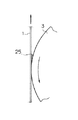
こうしてグラビアロール3の外周面に充填された所定量の塗料12は、その後、グラビアロール3の回転とともに周回移動して塗料供給器4と反対側、つまり支持体1側に移送される。このとき、支持体1とグラビアロール3との接触部分(線接触部分)には、図5に示すように、塗料による転写ビード(溜まり)25が形成される。
【0034】
ここで本実施形態においては、2つのガイドロール2によって略垂直姿勢に支持された支持体1を一方向に連続的に走行させるとともに、この走行中の支持体1にグラビアロール3を水平方向から略線接触させ、その接触位置でロール外周部が下向きに移動するようにグラビアロール3を回転させるようにしている。そのため、両者の接触位置で塗料12により形成される転写ビード25には、グラビアロール3の軸方向に渡ってほぼ均一に重力が加えられる。これにより転写ビード25は、重力に抑えられるかたちでダム状となり、この状態で楔形のビード形成がなされる。そのため、塗布速度の高速化への対応としてグラビアロール3を高速で回転させた場合でも、転写ビード25が泳ぎや乱れを引き起こすことなく安定的に保持される。
【0035】
その結果、支持体1に対するグラビアロール3の接触圧を弱めたうえで、両者の接触状態(線接触)に対応した幅狭の転写ビード25を形成することができる。したがって、ガイドロール2に支持される支持体1の張力を低下させることができるとともに、グラビアロール3に対する支持体1の抱き角度をほぼゼロにして、支持体1上に精度の高い均質な薄膜層(塗膜)を形成することができる。
【0036】
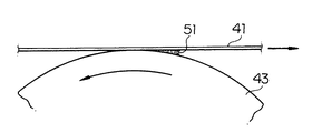
ちなみに、先の図10に示す塗布装置においても、支持体41とグラビアロール43との接触位置で図6のように塗料の転写ビード51が楔形に形成されるものの、この場合は転写ビード51が支持体41の走行方向に広がるため、乱れや泳ぎによる被れ等を発生しやすい状態となる。また、グラビアロール43の回転方向と反対方向に塗料を引き戻すように重力が作用することから、転写ビード51がダム状にならない。そのため、上記の乱れ等によって塗料が飛散する場合がある。特に、高速で塗料を塗布する場合は、転写ビード51が耐え切れずに飛び出すことがあり、塗膜形成の品質に悪影響を及ぼす。
【0037】
これに対して本実施形態の塗布装置を用いた場合は、転写ビード25が重力に抑えられて安定状態となるため、極細のビード形成を実現することができる。また、高速塗布に際しても、塗料の飛び出しがないため、塗膜形成の品質を良好に維持することができる。
【0038】
ここで、上記構成からなる塗布装置やこれを用いた塗布方法によって磁気記録媒体を製造する場合、特に磁性塗料を支持体上に塗布して磁性層を形成する場合について説明する。
【0039】
この場合、非塗布媒体となる支持体1としては、ポリエチレンテレフタレート、ポリエチレンなどのポリエステル樹脂や放香属ポリアミド樹脂フィルム等を用いることができる。
【0040】
また、塗料としての磁性塗料は、磁性粉と結合剤を溶剤で混練分散して構成することができる。磁性粉には、例えばFe−Co、Fe−Ni、Fe−Co−Ni、Co−Ni、Fe−Mn−Zn、Fe−Co−Ni−P、Fe−Co−Cr−B等のFe、Co、Niを主成分とする金属粒子を用いることが好適である。
【0041】
結合剤としては、例えば塩化ビニリデン、アクリル酸エステル、メタクリル酸エステル、スチレンブタジエン、アクリロニトリル等の重合体、あるいは共重合体であるポリウレタン樹脂、ポリエステル樹脂等を用いることができる。
【0042】
溶剤としては、従来公知のものがいずれも使用可能である。例えば、アセトン、メチルエチルケトン、メチルイソプチルケトン、シクロヘキサノン等のケトン系、酢酸メチル、酢酸エチル等のエステル系、グリコールジメチルエーテル、ジオキサン等のグリコールエーテル系、トルエン、キシレン等の芳香属酸化水素等を用いることができる。
【0043】
さらに添加剤として、分散剤、内添剤、研磨剤、耐電防止剤、防錆剤等を加えるようにしてもよい。また、非磁性塗料としては、ケッチェンブラックカーボン粉末等のバックコート層、潤剤を主としたトップコート層等を形成してもよい。
【0044】
【実施例】
本実施例においては、厚さ9.0μmのポリエステルフィルムからなる支持体1を使用し、その走行速度を300m/分として下記組成の磁性塗料を塗布することとした。また、塗布直後の平滑化(平坦化)処理を行わず、配向処理、乾燥処理を経てカレンダー表面処理を行い、そこで膜厚1.5±0.2μmとし、その強磁性体の裏面側に0.5μm厚で非磁性のバックコート層を塗布した後、8mm幅に裁断してテープ状の磁気記録媒体(磁気テープ)を作製した。
【0045】
[磁性塗料の組成]
金属磁性粉 100重量部
バインダー樹脂 20重量部
研磨剤:Al2O3 3重量部
導電剤:カーボン粉末 2重量部
メチルエチルケトン 100重量部
トルエン 100重量部
シクロヘキサノン 50重量部
【0046】
塗布条件としては、グラビアロールの直径が40mm〜60mm、セルパターンの種類は軸角度60°の亀甲型、格子型とし、セルパターンの幅(彫刻幅)は支持体1の両端を基準として各端+5mm〜+10mmとした。また、支持体1の張力は0.8N/cm〜2.4N/cm、グラビアロール3への支持体1の抱き角度は無し(ゼロ)として、それぞれの塗布状況を評価観察した。塗布状況の評価観察項目としては、グラビアロール3の周速度を305m/分とし、その時の塗料の塗布状態(塗りムラや厚みムラなどの有無)、巻き上がりロール2000m〜5000mでのロール形状、及び支持体全幅塗布の状況などを観察した。
【0047】
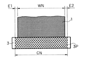
また、全幅塗布を行うにあたっては、貯溜部13からの塗料の滲みや計量用ドクターブレード8からの掻き取り余剰塗料がグラビアロール3の両端に流れ込まないように防止しているサイドシールウォール15がセルパターン3Pの彫刻領域に入らないよう、図7に示すように、グラビアロール3におけるセルパターン3Pの彫刻幅CNを、支持体1の幅WNの両端(左右)にそれぞれE1=E2≧5mmの余裕を設けて全幅塗布を行った。
【0048】
その結果、いずれの塗布条件においても、塗料の塗布状態が良好でかつ巻き上がりのロール形状が良い状態となった。また、支持体1の両端まで汚れや塗料飛散などの影響がない状態で全幅塗布することができ、塗膜厚の均一性や表面性に優れた塗布状態が得られた。支持体1の全幅に均一に塗料を塗布することができれば、生産性の向上や後処理工程(カレンダー工程、裁断工程)で端部の欠点による不良が減少し、さらにはテープ素材の節約などが図られるため、コスト低減に大いに寄与するものとなる。
【0049】
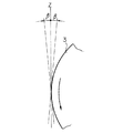
なお、2つのガイドロール2間で支持される支持体1の姿勢角度としては、重力による転写ビード25の安定性を考慮すると、図8に示すように、支持体1と垂直軸Zとがなす角度をβ=15°以下に設定することが好ましく、さらに好ましくはβ=10°以下、さらに好ましくはβ=5°以下に設定することが望ましい。
【0050】
【発明の効果】
以上説明したように本発明によれば、支持体とグラビアロールとの接触部分に幅狭の転写ビードを形成し、かつその転写ビードを重力によって安定状態に保持することができる。そのため、塗布速度の高速化への対応としてグラビアロールの回転速度を速めた場合でも、転写ビードの泳ぎや乱れを回避することができるとともに、転写ビードからの塗料の飛散を防止することができる。その結果、高速塗布を実施した場合でも、支持体の全幅にわたって均一な厚みで塗料を塗布することができるとともに、支持体上に均質な塗膜(薄膜層)を形成することができる。
【図面の簡単な説明】
【図1】本発明の実施形態に係る塗料の塗布装置の構成を示す側面概略図である。
【図2】本発明の実施形態における支持体とグラビアロールの配置状態を示す斜視図である。
【図3】本発明の実施形態における塗料供給器の構成を示す側断面図である。
【図4】本発明の実施形態における塗料供給器の構成を示す分解斜視図である。
【図5】本発明の実施形態における転写ビードの形成状態を示す側面図である。
【図6】従来における転写ビードの形成状態を示す側面図である。
【図7】支持体に全幅塗布を行う場合の各部の寸法関係を説明する図である。
【図8】支持体を垂直姿勢に支持する際の角度範囲を説明する図である。
【図9】従来の塗布装置の構成例を示す概略側面図である。
【図10】従来の塗布装置の他の構成例を示す概略側面図である。
【符号の説明】
1…支持体、2…ガイドロール、3…グラビアロール、4…塗料供給器[0001]
BACKGROUND OF THE INVENTION
The present invention relates to a coating apparatus and a coating method, and more particularly to a coating apparatus and a coating method that are suitable for use in manufacturing a magnetic recording medium such as a magnetic tape.
[0002]
[Prior art]
In general, in audio tapes, video tapes, backup data cartridges, etc., ferromagnetic powder, binder, dispersant, lubricant, etc. are dispersed and kneaded in an organic solvent on a non-magnetic support such as polyethylene terephthalate. A magnetic layer is formed by applying a magnetic paint. As a method for stably applying such a magnetic paint on a support, a gravure coating method has been widely used from the viewpoint of excellent high-speed workability, easy operation and management, and low production costs. Yes.
[0003]
In the gravure coating method, a coating material is applied to a support using a gravure roll having a gravure engraving on the outer peripheral surface of the roll. Further, among the gravure coating methods, there is a so-called reverse roll coating method in which the gravure roll is rotated in the opposite direction with respect to the traveling direction of the support. According to this reverse roll coating method, a flat coating film can be obtained without realizing a high-speed productivity and without performing a smoothing process (smoothing process) after coating the paint. The reverse roll coating method is roughly divided into a kiss reverse coating method and a mini kiss reverse coating method. The kiss reverse coating method and the mini kiss reverse method differ only in the diameter of the gravure roll used, and the basic coating principle is the same. Hereinafter, the structure of the conventional coating apparatus which employ | adopted the kiss reverse coating system is demonstrated.
[0004]
FIG. 9 is a schematic side view showing a configuration example of a conventional coating apparatus. In the figure, the
[0005]
Further, a
[0006]
In the coating apparatus having the above-described configuration, the
[0007]
FIG. 10 is a schematic side view showing another configuration example of a conventional coating apparatus. In the illustrated coating apparatus, the
[0008]
In the coating apparatus having the above-described configuration, the
[0009]
[Problems to be solved by the invention]
Incidentally, in the conventional coating apparatus shown in FIG. 9, the
[0010]
On the other hand, in the conventional coating apparatus shown in FIG. 10, since the holding angle (wrapping angle) of the
[0011]
However, in the coating apparatus shown in FIG. 10, since the transfer bead spreads in the traveling direction of the
[0012]
The present invention has been made to solve the above-described problems, and an object of the present invention is to provide a coating material coating apparatus and a coating method that can appropriately cope with an increase in coating speed.
[0013]
[Means for Solving the Problems]
The coating material coating apparatus according to the present invention is a support that continuously travels in one direction by a driving means. And a gravure roll disposed horizontally in a direction orthogonal to the travel direction of the support, and the travel support On the other hand, the rotating gravure roll is contacted to apply the paint, and the driving means has a guide member that supports the support body in a substantially vertical position, and the support body supported in a substantially vertical position by the guide member The Along the vertical direction The gravure roll travels from the bottom to the top, and the gravure roll is supported on the support body supported in a substantially vertical posture by the guide member so that the wrapping angle of the support body with respect to the gravure roll becomes substantially zero. From the horizontal direction It is arranged in a substantially line contact state, and rotates so that the outer periphery of the roll moves downward in the direction opposite to the traveling direction of the support at the contact position with the support. As a result, a wedge-shaped bead made of paint is formed at the position of contact with the support. The configuration is adopted.
[0014]
In this coating material coating apparatus, the support member is supported in a substantially vertical posture by the guide member, the gravure roll is brought into substantially line contact with the support member, and the outer peripheral portion of the roll moves downward at the contact position. As a result of the rotation, a narrow transfer bead is formed at the contact portion between the gravure roll and the support, and the transfer bead is stably held by gravity.
[0015]
In addition, the coating method according to the present invention includes a support that travels in one direction. And a gravure roll disposed horizontally in a direction orthogonal to the travel direction of the support, and a support that travels On the other hand, the rotating gravure roll is contacted to apply the paint, while supporting the support body in a substantially vertical posture at a predetermined position. Along the vertical direction The gravure roll is rotated so that the roll outer periphery moves in a direction opposite to the running direction of the support at the position of contact with the support, and the gravure roll rotates at the position where it contacts the support. To the support at a predetermined position so that the wrapping angle of the support with respect to the gravure roll is substantially zero. From the horizontal direction Make contact Thus, a wedge-shaped bead made of paint is formed at the contact position. The method is adopted.
[0016]
In this coating method, the support is supported in a substantially vertical position at a predetermined position, the gravure roll is brought into substantially line contact with the support, and the outer periphery of the roll is moved downward at the contact position. By rotating the roll, a narrow transfer bead is formed at the contact portion between the gravure roll and the support, and the transfer bead is stably held by gravity.
[0017]
DETAILED DESCRIPTION OF THE INVENTION
Hereinafter, embodiments of the present invention will be described in detail with reference to the drawings.
[0018]
FIG. 1 is a schematic side view showing a configuration of a coating material coating apparatus according to an embodiment of the present invention. In FIG. 1, a support 1 that is a medium to be coated is made of, for example, a long resin film, and is unwound from a unillustrated unwinding machine and travels on a predetermined route, and is then wound around a unillustrated winding machine. It is supposed to be. Examples of the support 1 include a magnetic tape, and more specifically, a base film of a magnetic recording medium such as a video tape or an audio tape, and a polyethylene terephthalate resin film is generally used because of its required characteristics. .
[0019]
The support 1 is supported by two guide rolls 2 in the course of the travel path from the unwinder to the winder. In this support state, the support body 1 is guided in the Y direction by the rotational drive of the above-described feeding machine and the winder, and the accompanying rotation operation of each
[0020]
The two guide rolls 2 are arranged in a state of facing each other up and down at an appropriate interval. Among these, the support body 1 is wound around the
[0021]
Further, between the two guide rolls 2 (intermediate portion), as shown in FIG. 2, a
[0022]
Further, between the two guide rolls 2, the
[0023]
In the vicinity of the
[0024]
The measuring
[0025]
The dam 9 forms a
[0026]
Further, the
[0027]
The
[0028]
With this configuration, a shielding space 18 is formed inside the
[0029]
The shielding space 18 faces the inclined surface of the dam 9, and the
[0030]
A
[0031]
Then, the coating method of the coating material based on the operation | movement procedure of the coating device which consists of the said structure is demonstrated. First, the paint (for example, magnetic paint) 12 to be applied to the support 1 is sent to the
[0032]
The
[0033]
The predetermined amount of the
[0034]
Here, in the present embodiment, the support 1 supported in a substantially vertical posture by the two guide rolls 2 is continuously run in one direction, and the
[0035]
As a result, after the contact pressure of the
[0036]
Incidentally, in the coating apparatus shown in FIG. 10, the
[0037]
On the other hand, when the coating apparatus of this embodiment is used, the
[0038]
Here, a case where a magnetic recording medium is manufactured by a coating apparatus having the above-described configuration and a coating method using the coating apparatus, particularly a case where a magnetic layer is formed by coating a magnetic coating on a support will be described.
[0039]
In this case, as the support 1 serving as a non-coating medium, a polyester resin such as polyethylene terephthalate or polyethylene, a fragrant polyamide resin film, or the like can be used.
[0040]
The magnetic paint as a paint can be constituted by kneading and dispersing magnetic powder and a binder with a solvent. Examples of the magnetic powder include Fe, Co such as Fe—Co, Fe—Ni, Fe—Co—Ni, Co—Ni, Fe—Mn—Zn, Fe—Co—Ni—P, Fe—Co—Cr—B, and the like. It is preferable to use metal particles mainly composed of Ni.
[0041]
As the binder, for example, a polymer such as vinylidene chloride, acrylic acid ester, methacrylic acid ester, styrene butadiene, acrylonitrile, or a copolymer polyurethane resin, polyester resin, or the like can be used.
[0042]
Any conventionally known solvent can be used. For example, use of ketones such as acetone, methyl ethyl ketone, methyl isobutyl ketone, cyclohexanone, esters such as methyl acetate and ethyl acetate, glycol ethers such as glycol dimethyl ether and dioxane, aromatic hydrogen oxides such as toluene and xylene, etc. Can do.
[0043]
Furthermore, you may make it add a dispersing agent, an internal additive, an abrasive | polishing agent, an antistatic agent, a rust preventive agent etc. as an additive. Further, as the nonmagnetic coating material, a backcoat layer such as ketjen black carbon powder, a topcoat layer mainly composed of a lubricant, and the like may be formed.
[0044]
【Example】
In this example, a support 1 made of a polyester film having a thickness of 9.0 μm was used, and a magnetic paint having the following composition was applied at a traveling speed of 300 m / min. Further, a smoothing (planarization) process immediately after coating is not performed, but a calendar surface process is performed through an alignment process and a drying process, and the film thickness is set to 1.5 ± 0.2 μm. A non-magnetic backcoat layer having a thickness of 0.5 μm was applied and then cut to a width of 8 mm to produce a tape-like magnetic recording medium (magnetic tape).
[0045]
[Composition of magnetic paint]
100 parts by weight of metal magnetic powder
20 parts by weight of binder resin
Abrasive: Al 2 O Three 3 parts by weight
Conductive agent: 2 parts by weight of carbon powder
100 parts by weight of methyl ethyl ketone
100 parts by weight of toluene
50 parts by weight of cyclohexanone
[0046]
The coating conditions are as follows: gravure roll diameter is 40 mm to 60 mm, cell pattern type is turtle shell type and lattice type with axis angle of 60 °, and cell pattern width (engraving width) is based on both ends of support 1 at each end. It was set to +5 mm to +10 mm. Moreover, the tension | tensile_strength of the support body 1 was 0.8 N / cm-2.4 N / cm, and the application | coating state of each was evaluated and observed as the holding angle of the support body 1 to the
[0047]
In addition, when performing full width coating, the side seal wall 15 that prevents the paint from spreading from the
[0048]
As a result, the coating state of the paint was good and the rolled-up roll shape was good under any coating condition. Moreover, it was possible to apply the full width to the both ends of the support 1 without being affected by dirt, paint scattering, etc., and an application state with excellent coating thickness uniformity and surface properties was obtained. If the coating can be applied uniformly over the entire width of the support 1, defects due to defects at the edges will be reduced in productivity and post-processing processes (calendar process, cutting process), and tape materials will be saved. Therefore, this greatly contributes to cost reduction.
[0049]
Note that the attitude angle of the support 1 supported between the two guide rolls 2 is defined by the support 1 and the vertical axis Z as shown in FIG. 8 in consideration of the stability of the
[0050]
【The invention's effect】
As described above, according to the present invention, a narrow transfer bead can be formed at the contact portion between the support and the gravure roll, and the transfer bead can be held in a stable state by gravity. For this reason, even when the rotation speed of the gravure roll is increased as a measure for increasing the coating speed, it is possible to avoid swimming and disturbance of the transfer bead and to prevent the paint from scattering from the transfer bead. As a result, even when high-speed coating is performed, the paint can be applied with a uniform thickness over the entire width of the support, and a uniform coating film (thin film layer) can be formed on the support.
[Brief description of the drawings]
FIG. 1 is a schematic side view illustrating a configuration of a coating material coating apparatus according to an embodiment of the present invention.
FIG. 2 is a perspective view showing an arrangement state of a support and a gravure roll in an embodiment of the present invention.
FIG. 3 is a side cross-sectional view showing a configuration of a paint supplier in an embodiment of the present invention.
FIG. 4 is an exploded perspective view showing a configuration of a paint supplier in an embodiment of the present invention.
FIG. 5 is a side view showing a formation state of a transfer bead in the embodiment of the present invention.
FIG. 6 is a side view showing a conventional transfer bead formation state.
FIG. 7 is a diagram for explaining a dimensional relationship of each part when full width application is performed on a support.
FIG. 8 is a diagram illustrating an angle range when a support is supported in a vertical posture.
FIG. 9 is a schematic side view showing a configuration example of a conventional coating apparatus.
FIG. 10 is a schematic side view showing another configuration example of a conventional coating apparatus.
[Explanation of symbols]
DESCRIPTION OF SYMBOLS 1 ... Support body, 2 ... Guide roll, 3 ... Gravure roll, 4 ... Paint feeder
Claims (9)
前記駆動手段は、前記支持体を略垂直姿勢に支持するガイド部材を有するとともに、当該ガイド部材によって略垂直姿勢に支持された前記支持体を垂直方向に沿って下から上に移動するように走行し、
前記グラビアロールは、当該グラビアロールに対する前記支持体の巻き付き角度がほぼゼロとなるように、前記ガイド部材によって略垂直姿勢に支持された支持体に水平方向から略線接触する状態で配置されるとともに、前記支持体との接触位置でロール外周部が前記支持体の走行方向と反対方向となる下向きに移動するように回転することにより、当該支持体との接触位置に塗料による楔形のビードを形成する
ことを特徴とする塗料の塗布装置。A support that travels in one direction by a driving means; and a gravure roll that is horizontally disposed in a direction perpendicular to the travel direction of the support , and the rotating gravure roll is brought into contact with the traveling support. In a coating device that applies paint,
The drive means has a guide member that supports the support body in a substantially vertical posture, and travels so that the support body supported in the substantially vertical posture by the guide member moves from bottom to top along the vertical direction. And
The gravure roll is disposed in a substantially line contact state from a horizontal direction on a support body supported in a substantially vertical posture by the guide member so that a winding angle of the support body with respect to the gravure roll becomes substantially zero. By rotating so that the outer periphery of the roll moves downward in the direction opposite to the traveling direction of the support at the position of contact with the support, a wedge-shaped bead made of paint is formed at the position of contact with the support An apparatus for applying a paint characterized in that:
ことを特徴とする請求項1記載の塗料の塗布装置。The paint application apparatus according to claim 1, wherein the guide member supports the support body in a substantially vertical posture so that an angle formed by the support body and a vertical axis is 15 ° or less.
前記塗料供給手段は、前記グラビアロールに供給すべき塗料を貯留する貯留部を形成するとともに、前記グラビアロールと対向する側の面が、前記グラビアロールの回転方向において順次グラビアロールの外周面に近接する傾斜面とされた堰を有する
ことを特徴とする請求項1記載の塗料の塗布装置。A paint supply means for supplying paint to the gravure roll on the opposite side of the contact position with the support;
The coating material supply means forms a reservoir for storing the coating material to be supplied to the gravure roll, and the surface facing the gravure roll sequentially approaches the outer peripheral surface of the gravure roll in the rotation direction of the gravure roll. The coating apparatus according to claim 1, further comprising a weir that is an inclined surface.
前記グラビアロールは、前記2つのガイド部材の間で略垂直姿勢に支持された前記支持体に略線接触する状態で配置される
ことを特徴とする請求項1記載の塗料の塗布装置。The drive means has two upper and lower guide members that support the support in a substantially vertical posture,
The coating apparatus for coating material according to claim 1, wherein the gravure roll is arranged in a substantially line contact with the support body supported in a substantially vertical posture between the two guide members.
ことを特徴とする請求項3記載の塗料の塗布装置。The coating apparatus for coating material according to claim 3, wherein a gradient angle of the inclined surface is set to 60 ° to 85 °.
ことを特徴とする請求項3記載の塗料の塗布装置。The coating device for coating material according to claim 3, wherein the tip width of the closest portion of the weir to the gravure roll is set to 0.5 mm to 3.0 mm.
前記支持体を所定の位置で略垂直姿勢に支持しつつ垂直方向に沿って下から上に移動するように走行させるとともに、前記支持体との接触位置でロール外周部が前記支持体の走行方向と反対方向となる下向きに移動するように前記グラビアロールを回転させ、この回転するグラビアロールを、当該グラビアロールに対する前記支持体の巻き付き角度がほぼゼロとなるように、前記所定の位置で前記支持体に水平方向から略線接触させることにより、当該接触位置に塗料による楔形のビードを形成する
ことを特徴とする塗料の塗布方法。Using a support that travels in one direction and a gravure roll that is horizontally disposed in a direction orthogonal to the travel direction of the support , a rotating gravure roll is brought into contact with the traveling support to paint In the application method of applying
While supporting the support body in a substantially vertical posture at a predetermined position, the support body is moved so as to move from bottom to top along the vertical direction, and the outer periphery of the roll is in the travel direction of the support body at the contact position with the support body The gravure roll is rotated so as to move downward in the opposite direction, and the rotating gravure roll is supported at the predetermined position so that the winding angle of the support with respect to the gravure roll becomes substantially zero. A paint coating method , wherein a wedge-shaped bead made of paint is formed at the contact position by making a substantially line contact with a body from a horizontal direction .
ことを特徴とする請求項7記載の塗料の塗布方法。The coating method according to claim 7, wherein the support is supported in a substantially vertical posture so that an angle formed by the support and a vertical axis is 15 ° or less at the predetermined position.
ことを特徴とする請求項7記載の塗料の塗布方法。The support is supported in a substantially vertical posture by two upper and lower guide members, and the gravure roll is brought into substantially line contact with the support supported in a substantially vertical posture between the two guide members. The coating method of the coating material of Claim 7.
Priority Applications (1)
| Application Number | Priority Date | Filing Date | Title |
|---|---|---|---|
| JP2000375444A JP3772669B2 (en) | 2000-12-11 | 2000-12-11 | Coating device and coating method |
Applications Claiming Priority (1)
| Application Number | Priority Date | Filing Date | Title |
|---|---|---|---|
| JP2000375444A JP3772669B2 (en) | 2000-12-11 | 2000-12-11 | Coating device and coating method |
Publications (3)
| Publication Number | Publication Date |
|---|---|
| JP2002177836A JP2002177836A (en) | 2002-06-25 |
| JP2002177836A5 JP2002177836A5 (en) | 2005-07-28 |
| JP3772669B2 true JP3772669B2 (en) | 2006-05-10 |
Family
ID=18844457
Family Applications (1)
| Application Number | Title | Priority Date | Filing Date |
|---|---|---|---|
| JP2000375444A Expired - Fee Related JP3772669B2 (en) | 2000-12-11 | 2000-12-11 | Coating device and coating method |
Country Status (1)
| Country | Link |
|---|---|
| JP (1) | JP3772669B2 (en) |
Families Citing this family (8)
| Publication number | Priority date | Publication date | Assignee | Title |
|---|---|---|---|---|
| JP3844005B1 (en) * | 2005-08-02 | 2006-11-08 | ソニー株式会社 | Coating device and coating method |
| JP5589242B2 (en) * | 2010-07-06 | 2014-09-17 | 株式会社暁機械製作所 | Coating device |
| JP6220656B2 (en) * | 2013-12-03 | 2017-10-25 | 富士機械工業株式会社 | Coating equipment |
| JP6213263B2 (en) * | 2014-01-28 | 2017-10-18 | 日本ゼオン株式会社 | Gravure coating equipment |
| JP6440568B2 (en) * | 2015-05-14 | 2018-12-19 | 株式会社日本製鋼所 | Gravure coating machine for heat-resistant material coating on lithium-ion battery separator |
| JP6819438B2 (en) * | 2017-04-21 | 2021-01-27 | トヨタ自動車株式会社 | Electrode plate manufacturing equipment |
| JP6437070B2 (en) * | 2017-09-19 | 2018-12-12 | 富士機械工業株式会社 | Coating equipment |
| JP6705516B2 (en) * | 2019-01-11 | 2020-06-03 | 日立化成株式会社 | Method for producing anisotropically conductive film |
-
2000
- 2000-12-11 JP JP2000375444A patent/JP3772669B2/en not_active Expired - Fee Related
Also Published As
| Publication number | Publication date |
|---|---|
| JP2002177836A (en) | 2002-06-25 |
Similar Documents
| Publication | Publication Date | Title |
|---|---|---|
| JP3772669B2 (en) | Coating device and coating method | |
| US5597615A (en) | Extrusion coating method and coating apparatus for coating both sides of a web | |
| JP3844005B1 (en) | Coating device and coating method | |
| JP2001321707A (en) | Coating equipment and method | |
| JP2001104851A (en) | Method and apparatus for applying paint | |
| JPH09141172A (en) | Coating device | |
| JP3114324B2 (en) | Coating device | |
| CN217062153U (en) | Lithium supplement device | |
| JP4407533B2 (en) | Application method | |
| JPH01173420A (en) | Magnetic recording medium provided with back coat layer containing nonmagnetic powder | |
| JP2691602B2 (en) | Coating method and device | |
| JPH02207865A (en) | Method and device for coating | |
| JP4891881B2 (en) | cartridge | |
| JPH10151391A (en) | Device and method for gravure coating | |
| JPH1176898A (en) | Coating apparatus | |
| US20060231024A1 (en) | Coating apparatus | |
| JP2629847B2 (en) | Manufacturing method of magnetic recording medium | |
| JP3321892B2 (en) | Manufacturing method of magnetic recording medium | |
| JPH091027A (en) | Coating device | |
| JPH0573905A (en) | Production of magnetic recording medium and apparatus thereof | |
| JP2000237663A (en) | Coating apparatus and coating method | |
| JP2007007572A (en) | Application method and apparatus | |
| JPH05208155A (en) | Rubber roll | |
| JP2005178996A (en) | Guide roll and magnetic tape manufacturing equipment | |
| JPH11169768A (en) | Coating device |
Legal Events
| Date | Code | Title | Description |
|---|---|---|---|
| A521 | Written amendment |
Free format text: JAPANESE INTERMEDIATE CODE: A523 Effective date: 20041210 |
|
| A621 | Written request for application examination |
Free format text: JAPANESE INTERMEDIATE CODE: A621 Effective date: 20041210 |
|
| A871 | Explanation of circumstances concerning accelerated examination |
Free format text: JAPANESE INTERMEDIATE CODE: A871 Effective date: 20041210 |
|
| A975 | Report on accelerated examination |
Free format text: JAPANESE INTERMEDIATE CODE: A971005 Effective date: 20050113 |
|
| A131 | Notification of reasons for refusal |
Free format text: JAPANESE INTERMEDIATE CODE: A131 Effective date: 20050118 |
|
| A521 | Written amendment |
Free format text: JAPANESE INTERMEDIATE CODE: A523 Effective date: 20050318 |
|
| A131 | Notification of reasons for refusal |
Free format text: JAPANESE INTERMEDIATE CODE: A131 Effective date: 20050426 |
|
| A521 | Written amendment |
Free format text: JAPANESE INTERMEDIATE CODE: A523 Effective date: 20050624 |
|
| A02 | Decision of refusal |
Free format text: JAPANESE INTERMEDIATE CODE: A02 Effective date: 20050913 |
|
| A521 | Written amendment |
Free format text: JAPANESE INTERMEDIATE CODE: A523 Effective date: 20051111 |
|
| A911 | Transfer of reconsideration by examiner before appeal (zenchi) |
Free format text: JAPANESE INTERMEDIATE CODE: A911 Effective date: 20051116 |
|
| TRDD | Decision of grant or rejection written | ||
| A01 | Written decision to grant a patent or to grant a registration (utility model) |
Free format text: JAPANESE INTERMEDIATE CODE: A01 Effective date: 20060124 |
|
| A61 | First payment of annual fees (during grant procedure) |
Free format text: JAPANESE INTERMEDIATE CODE: A61 Effective date: 20060206 |
|
| FPAY | Renewal fee payment (event date is renewal date of database) |
Free format text: PAYMENT UNTIL: 20100224 Year of fee payment: 4 |
|
| FPAY | Renewal fee payment (event date is renewal date of database) |
Free format text: PAYMENT UNTIL: 20100224 Year of fee payment: 4 |
|
| FPAY | Renewal fee payment (event date is renewal date of database) |
Free format text: PAYMENT UNTIL: 20110224 Year of fee payment: 5 |
|
| FPAY | Renewal fee payment (event date is renewal date of database) |
Free format text: PAYMENT UNTIL: 20120224 Year of fee payment: 6 |
|
| FPAY | Renewal fee payment (event date is renewal date of database) |
Free format text: PAYMENT UNTIL: 20130224 Year of fee payment: 7 |
|
| LAPS | Cancellation because of no payment of annual fees |