JP3772666B2 - Vehicle foot-operated parking brake device - Google Patents
Vehicle foot-operated parking brake device Download PDFInfo
- Publication number
- JP3772666B2 JP3772666B2 JP2000354207A JP2000354207A JP3772666B2 JP 3772666 B2 JP3772666 B2 JP 3772666B2 JP 2000354207 A JP2000354207 A JP 2000354207A JP 2000354207 A JP2000354207 A JP 2000354207A JP 3772666 B2 JP3772666 B2 JP 3772666B2
- Authority
- JP
- Japan
- Prior art keywords
- release
- pedal arm
- release lever
- pole
- parking brake
- Prior art date
- Legal status (The legal status is an assumption and is not a legal conclusion. Google has not performed a legal analysis and makes no representation as to the accuracy of the status listed.)
- Expired - Fee Related
Links
Images
Classifications
-
- B—PERFORMING OPERATIONS; TRANSPORTING
- B60—VEHICLES IN GENERAL
- B60T—VEHICLE BRAKE CONTROL SYSTEMS OR PARTS THEREOF; BRAKE CONTROL SYSTEMS OR PARTS THEREOF, IN GENERAL; ARRANGEMENT OF BRAKING ELEMENTS ON VEHICLES IN GENERAL; PORTABLE DEVICES FOR PREVENTING UNWANTED MOVEMENT OF VEHICLES; VEHICLE MODIFICATIONS TO FACILITATE COOLING OF BRAKES
- B60T7/00—Brake-action initiating means
- B60T7/02—Brake-action initiating means for personal initiation
- B60T7/04—Brake-action initiating means for personal initiation foot actuated
- B60T7/045—Brake-action initiating means for personal initiation foot actuated with locking and release means, e.g. providing parking brake application
- B60T7/047—Hand-actuated release means
-
- B—PERFORMING OPERATIONS; TRANSPORTING
- B60—VEHICLES IN GENERAL
- B60T—VEHICLE BRAKE CONTROL SYSTEMS OR PARTS THEREOF; BRAKE CONTROL SYSTEMS OR PARTS THEREOF, IN GENERAL; ARRANGEMENT OF BRAKING ELEMENTS ON VEHICLES IN GENERAL; PORTABLE DEVICES FOR PREVENTING UNWANTED MOVEMENT OF VEHICLES; VEHICLE MODIFICATIONS TO FACILITATE COOLING OF BRAKES
- B60T11/00—Transmitting braking action from initiating means to ultimate brake actuator without power assistance or drive or where such assistance or drive is irrelevant
- B60T11/04—Transmitting braking action from initiating means to ultimate brake actuator without power assistance or drive or where such assistance or drive is irrelevant transmitting mechanically
- B60T11/046—Using cables
-
- B—PERFORMING OPERATIONS; TRANSPORTING
- B60—VEHICLES IN GENERAL
- B60T—VEHICLE BRAKE CONTROL SYSTEMS OR PARTS THEREOF; BRAKE CONTROL SYSTEMS OR PARTS THEREOF, IN GENERAL; ARRANGEMENT OF BRAKING ELEMENTS ON VEHICLES IN GENERAL; PORTABLE DEVICES FOR PREVENTING UNWANTED MOVEMENT OF VEHICLES; VEHICLE MODIFICATIONS TO FACILITATE COOLING OF BRAKES
- B60T7/00—Brake-action initiating means
- B60T7/02—Brake-action initiating means for personal initiation
- B60T7/04—Brake-action initiating means for personal initiation foot actuated
- B60T7/045—Brake-action initiating means for personal initiation foot actuated with locking and release means, e.g. providing parking brake application
-
- Y—GENERAL TAGGING OF NEW TECHNOLOGICAL DEVELOPMENTS; GENERAL TAGGING OF CROSS-SECTIONAL TECHNOLOGIES SPANNING OVER SEVERAL SECTIONS OF THE IPC; TECHNICAL SUBJECTS COVERED BY FORMER USPC CROSS-REFERENCE ART COLLECTIONS [XRACs] AND DIGESTS
- Y10—TECHNICAL SUBJECTS COVERED BY FORMER USPC
- Y10T—TECHNICAL SUBJECTS COVERED BY FORMER US CLASSIFICATION
- Y10T74/00—Machine element or mechanism
- Y10T74/20—Control lever and linkage systems
- Y10T74/20576—Elements
- Y10T74/20636—Detents
- Y10T74/20672—Lever engaging rack
- Y10T74/20684—Lever carried pawl
-
- Y—GENERAL TAGGING OF NEW TECHNOLOGICAL DEVELOPMENTS; GENERAL TAGGING OF CROSS-SECTIONAL TECHNOLOGIES SPANNING OVER SEVERAL SECTIONS OF THE IPC; TECHNICAL SUBJECTS COVERED BY FORMER USPC CROSS-REFERENCE ART COLLECTIONS [XRACs] AND DIGESTS
- Y10—TECHNICAL SUBJECTS COVERED BY FORMER USPC
- Y10T—TECHNICAL SUBJECTS COVERED BY FORMER US CLASSIFICATION
- Y10T74/00—Machine element or mechanism
- Y10T74/20—Control lever and linkage systems
- Y10T74/20576—Elements
- Y10T74/20888—Pedals
-
- Y—GENERAL TAGGING OF NEW TECHNOLOGICAL DEVELOPMENTS; GENERAL TAGGING OF CROSS-SECTIONAL TECHNOLOGIES SPANNING OVER SEVERAL SECTIONS OF THE IPC; TECHNICAL SUBJECTS COVERED BY FORMER USPC CROSS-REFERENCE ART COLLECTIONS [XRACs] AND DIGESTS
- Y10—TECHNICAL SUBJECTS COVERED BY FORMER USPC
- Y10T—TECHNICAL SUBJECTS COVERED BY FORMER US CLASSIFICATION
- Y10T74/00—Machine element or mechanism
- Y10T74/21—Elements
- Y10T74/2133—Pawls and ratchets
- Y10T74/2136—Pivoted pawls
- Y10T74/2137—Single tooth
Landscapes
- Engineering & Computer Science (AREA)
- Transportation (AREA)
- Mechanical Engineering (AREA)
- Braking Elements And Transmission Devices (AREA)
Description
【0001】
【発明の属する技術分野】
本発明は、自動車等の車両の足踏式パーキングブレーキ装置に関し、特に、パーキングブレーキ作用時と同じ操作を行うことでパーキングブレーキ解除ができるようにした車両用足踏式パーキングブレーキ装置に関するものである。
【0002】
【従来の技術】
この種の従来の車両用足踏式パーキングブレーキ制御装置としては、例えば、特許第2967406号に記載されたものがある。このものでは、ペダルアームに設けたラチェット歯と係合させペダルアームをロックさせるポールをブラケットに回動可能且つペダルアームの回動方向に所定量スライド可能にピンにより支持すると共に、ポールに係合可能なレリーズレバーをブラケットに回動可能にピンにより支持し、一端及び他端をポール及びレリーズレバーに夫々取付けたスプリングのポール及びレリーズレバーに対する付勢の方向をペダルアームの回動に応じて切換えるようにしている。
【0003】
即ち、パーキングブレーキの解除状態では、スプリングはポールをラチェット歯と係合させる方向へ付勢していると共にレリーズレバーをラチェット歯から離反する方向へ付勢している。ペダルが踏込まれてペダルアームが回動すると、ポールとラチェット歯との係合によってペダルアームの戻りが阻止され、パーキングブレーキの作用が維持される。この際、ペダルの踏込みを解除した時にポールがペダルアームの戻り方向へ所定量スライドしてレリーズレバーをラチェット歯に接近する側に回動させ、スプリングがポールをラチェット歯から離脱する方向に付勢するようになると共にレリーズレバーをラチェット歯に接近する側に付勢するようになる。このパーキングブレーキ作用状態にて、ペダルが踏込まれてペダルアームが回動すると、ポールとラチェット歯との圧接が解かれてポールがラチェット歯から離脱する方向に回動し、これによりペダルアームの戻りが許容され、パーキングブレーキが解除される。
【0004】
【発明が解決しようとする課題】
しかしながら、上記した従来の装置においては、ラチェット歯がペダルアームに列設され、ポール及びレリーズレバーがブラケットに取り付けられる構成であるため、ブラケットの大型化に起因して、当該パーキングブレーキ装置が大型化し、車両への搭載に際してスペース上の制約を受ける恐れがあるという問題があった。尚、この問題は、ペダルの踏込みによりペダルアームを回動しパーキングブレーキを作用させた後に踏込みを解除したときにペダルアームがパーキングブレーキの効きを弱める方向に戻るロスストロークを小さくするために、ペダルアームの回動軸からラチェット歯の円弧の距離を大きくすると、より顕著となる。
【0005】
ゆえに、本発明は、当該車両用足踏式パーキングブレーキ装置において、小型化を図りつつ、ロスストロークを小さくすることを、その課題とする。
【0006】
【課題を解決するための手段】
上記技術的課題を解決するために本発明により講じた手段は、当該車両用足踏式パーキングブレーキ装置を、車体に固定される取付け用のブラケットと、前記ブラケットに略水平に設けられた軸部材に回動可能に枢支される主ペダルアームと前記軸部材に枢支されると共に前記軸部材に平行な連結ピンによって前記主ペダルアームに連結されて前記主ペダルアームと一体で回動可能な副ペダルアームとからなるペダルアームと、前記ブラケットに前記軸部材と同心の円弧に沿って列設された多数のラチェット歯と、前記連結ピンに長孔を介して枢支されて前記ラチェット歯に係合した第1回動位置と前記ラチェット歯から離脱した第2回動位置との間を回動すると共に第1スライド位置と第2スライド位置との間を前記ペダルアームの回動方向にスライドするポールと、前記連結ピンに回動可能に取り付けられていてレリーズ回動位置と非レリーズ回動位置との間を回動するレリーズレバーと、一端及び他端を前記ポール及び前記レリーズレバーに夫々取り付けられ、前記レリーズレバーが前記非レリーズ回動位置にある時には前記ポールを前記第1回動位置に回動させるように付勢すると共に前記レリーズレバーを前記非レリーズ回動位置に保持するように付勢し、更に、前記レリーズレバーが前記レリーズ回動位置にある時には前記ポールを前記第2回動位置に回動させるように付勢すると共に前記レリーズレバーを前記レリーズ回動位置に保持するように付勢するスプリングと、前記ポールが前記第1スライド位置から前記第2スライド位置に移動したときには前記レリーズレバーを前記非レリーズ回動位置から前記レリーズ回動位置へ回動させるように前記ポールと前記レリーズレバーとの間に設けられた第1連動手段と、前記ペダルアームがパーキングブレーキ作用位置からパーキングブレーキ解除位置へ回動したときには前記レリーズレバーを前記レリーズ回動位置から前記非レリーズ回動位置へ回動させるように前記レリーズレバーと前記ブラケットとの間に設けられた第2連動手段とを備えた構成としたことである。
【0007】
上記した手段によれば、パーキングブレーキの解除状態にてペダルアームを踏込めばポールとラチェット歯との係合によりペダルアームの戻りが阻止され、パーキングブレーキの作用が維持される。その際、ペダルアームの踏込みを解除した時にポールがペダルアームの戻り方向へ所定量スライドしてレリーズレバーが回動しスプリングがポールをラチェット歯から離脱させる方向へ付勢するようになり、従って再びペダルアームを踏込みポールとラチェット歯との圧接を解くことでポールがラチェット歯から離脱しペダルアームの戻りが許容され、パーキングブレーキが解除される。詳細には、ペダルアームを踏込んでパーキングブレーキを作用させた後、踏込みを解除した時にポールが第1スライド位置から第2スライド位置にスライドし、このスライドによりレリーズレバーが非レリーズ回動位置からレリーズ回動位置へ回動し、ポールを第1回動位置に回動させるように付勢していたスプリングはその他端がレリーズレバーの回動により変位されることでポールを第2回動位置へ回動させるように付勢する。
【0008】
また、ポール及びレリーズレバーはペダルアームに取り付けられ、ポールに係合可能なラチェット歯はペダルアームの揺動軌跡内に位置されるブラケットに設けられる。このため、従来装置に比しブラケットの小型化を図ることが可能となると共に、車両への搭載に際してスペース上の制約を受ける恐れを招くことなくペダルアームの回動軸からラチェット歯の円弧の距離を大きくすることができて、ロスストロークを小さくすることが可能となる。
【0009】
尚、上記した手段においては、ポールは長孔の延在方向に対して略直角方向且つペダルアームの長手方向に延びる長腕部を有し、レリーズレバーはペダルアームの長手方向に延びる長腕部を有し、スプリングの一端及び他端がポールの長腕部及びレリーズレバーの長腕部に夫々取り付けられることが望ましい。
【0010】
【発明の実施の形態】
以下、本発明に従った車両用足踏式パーキングブレーキ装置の一実施形態を図面に基づいて説明する。
【0011】
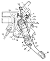
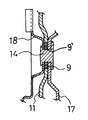
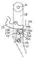
図1乃及び図2において、車体への取付け用のブラケット11には、主ペダルアーム17及び副ペダルアーム18が軸部材14により一体で回動可能に枢支されている。図2に示されるように、主ペダルアーム17は、図1ではブラケット11の奥側に位置し、副ペダルアーム18は図1ではブラケット11の手前側に位置し、両ペダルアーム17、18でブラケット11を挟むように構成されている。主ペダルアーム17と副ペダルアーム18とは、軸部材14とは別に後述するように連結ピン15により連結されている。尚、図2において、9、9’はカラーである。
【0012】
主ペダルアーム17の長手方向の一端には、ペダルパッド10が取り付けられ、他端側には外方に開口する溝部17dが形成されている。該溝17d内には、一端が主ペダルアーム17の取付部17eにダブルナット19により取り付けられたパーキングブレーキ制御ケーブル20が巻かれている。パーキングブレーキ制御ケーブル20の他端は、車輪ブレーキ機構(図示省略)と作動的に連結されており、主及び副ペダルアーム17、18が図1において軸部材14を中心として図示位置から時計方向に回動することによりパーキングブレーキ制御ケーブル20が牽引されて、車輪ブレーキ機構が作動され、パーキングが作用する。主及び副ペダルアーム17、18は、ブラケット11のスプリング係止部11bと主ペダルアーム17のスプリング係止部17bとの間に張設されたリターンスプリング22により図1において軸部材14を中心として反時計方向に回動するように付勢されている。図1における主及び副ペダルアーム17、18の反時計方向への回動は、ブラケット11に固定されたゴム製のストッパ21に主ペダルアーム17の当接部17aが当接することで規制される。
【0013】
主ペダルアーム17が踏込まれた場合に主ペダルアーム17を車輪ブレーキ機構が作動した位置に保持するため、図1及び図4〜図7に示すように、主ペダルアーム17の軸部材14を中心とした揺動軌跡内に位置するブラケット11の下方部に多数のラチェット歯23aを有するセクタ部材23が連結ピン24により固定されており、ラチェット歯23aの1つと係合可能な爪25aを有するポール25が主ペダルアーム17に連結ピン15を中心として回動可能に設置されている。ラチェット歯23aは主ペダルアーム17の回動中心である軸部材14と同心の円弧の上に配列されている。
【0014】
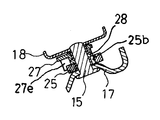
図1及び図3に示すように、主ペダルアーム17と副ペダルアーム18とを連結する連結ピン15により、主ペダルアーム17にはポール25及びレリーズレバー27とがカラー28を介して回動可能に枢支されている。ポール25は、図5に示されるようにラチェット歯23aに係合した第1回動位置と図7に示されるようにラチェット歯23aから離脱した第2回動位置との間を回動可能とされている。連結ピン15を貫通させるポール25の孔25bは主ペダルアーム17の回動方向(揺動方向)に延在する長孔とされており、これによりポール25は図4及び図5に示される第1スライド位置と図6及び図7に示される第2スライド位置との間をスライド可能とされている。
【0015】
ポール25を第1回動位置と第2回動位置のいずれかに選択的に回動付勢させるとともにポール25を第1スライド位置にスライドさせるように付勢させるためのトーションスプリング26は、その一端26aをポール25の孔25cに係止され、またその他端26bをレリーズレバー27の孔27aに係止されている。ポール25は、孔25bの延在方向に対して略直角方向且つ主ペダルアーム17の長手方向にペダルパッド10側に延びる長腕部25Aと、長腕部25Aに対して孔25bから反対側に延びる短腕部25Bを有し、長腕部25Aの端部に孔25cが形成され、短腕部25Bの端部に爪25aが形成されている。レリーズレバー27は、主ペダルアーム17の長手方向にペダルパッド10側に延びる長腕部27bと、長腕部27bに対して連結ピン15から反対側に延びる短腕部27cを有し、長腕部27の端部に孔27aが形成されている。レリーズレバー27は、図4及び図5に示される非レリーズ回動位置と図6及び図7に示されるレリーズ回動位置との間を回動可能とされている。
【0016】
ポール25が、図4及び図5の第1スライド位置から図6及び図7の第2スライド位置へスライドすることによりレリーズレバー27を図4及び図5の非レリーズ回動位置から図6及び図7のレリーズ回動位置へ回動させるため、ポール25の短腕部25Bには当接部25dが形成され、レリーズレバー27の短腕部27cには当接部25dに当接可能な突起部27eが形成されている(図3参照)。
【0017】
また、図6及び図7のレリーズ回動位置にあるレリーズレバー27を主ペダルアーム17の通常位置(パーキングブレーキが解除状態となっている図1に示す位置)への復帰動作により非レリーズ回動位置に回動させるために、主ペダルアーム17の通常位置にてレリーズレバー27の短腕部27cの先端が当接可能な当接部11aがブラケット11には形成されている。
【0018】
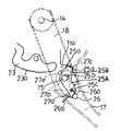
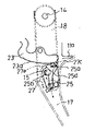
以上の構成から成る本実施形態の作用を説明する。図1及び図4は、パーキングブレーキを作用させていない状態を示している。パーキングブレーキを作用させるために主ペダルアーム17が踏込まれた場合、主ペダルアーム17及び副ペダルアーム18が図1及び図4において軸部材14を中心として時計方向に回動し、パーキングブレーキ制御ケーブル20を牽引し、車輪ブレーキ機構が作動する。主ペダルアーム17の回動により、トーションスプリング26によって第1回動位置へ向けて回動付勢されているポール25の爪25aが多数のラチェット歯23aの一つと係合する。この状態が図5に示されている。
【0019】
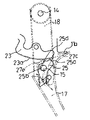
図5は、主ペダルアーム17に踏力が加えられている状態であり、主ペダルアーム17から踏力が除去されると、車輪ブレーキ機構からパーキングブレーキ制御ケーブル20を介して主ペダルアーム17に加わっている反力及びリターンスプリング22の付勢力により、主ペダルアーム17及び副ペダルアーム18がポール25の孔25bと連結ピン15の隙間分だけ反時計方向に図6の位置まで回動し、それに伴ってラチェット歯23aに係合しているポール25は第1スライド位置から図6に示す第2スライド位置にスライドする。ポール25が図5の第1スライド位置から図6の第2スライド位置へスライドする過程において、ポール25の短腕部25Bの当接部25dがレリーズレバー27の突起部27eに当接してレリーズレバー27を連結ピン15を中心として反時計方向へ回動させ、レリーズレバー27が図5の非レリーズ回動位置から図6のレリーズ回動位置へ回動する。レリーズレバー27がレリーズ回動位置へ回動すると、トーションスプリング26の姿勢が図6に示すように変化し、トーションスプリング26はポール25を第2回動位置へ回動させるように付勢するようになるが、車輪ブレーキ機構から主ペダルアーム17に加わる反力により図6に実線の矢印で示すような力がポール25に作用しラチェット歯23aと爪25aとが強く係合されているので、ポール25は第1回動位置に保持される。従って、パーキングブレーキが作用する。尚、レリーズレバー27がレリーズ回動位置へ回動することによりレリーズレバー27の短腕部27cの先端が、主ペダルアーム17がパーキングブレーキを作用させていない状態位置に戻される際にブラケット11の当接部11aに当接するようにラチェット歯23a側に突出する。
【0020】
このように、ポール25が第1スライド位置から第2スライド位置にスライドすることによりトーションスプリング26のポール付勢方向が切り換わるのであり、この切り換わりを確実にするためにはトーションスプリング26の他端26bの移動量を多くする必要があるが、ポール25のスライド量はパーキングブレーキの効きを下げることに繋がるので少ないことが必要である。本実施形態においては、レリーズレバー27がポール25のスライドとトーションスプリング26の他端26bの移動との関係においてポール25のスライド量を拡大して他端26bの移動量とする。ここで、トーションスプリング26の一端26aが係止されるポール25の長腕部25Aは、孔25bの延在方向に対して略直角方向且つ主ペダルアーム17の長手方向にペダルパッド10側に延び、トーションスプリング26の他端26bが係止されるレリーズレバー27の長腕部27bは、主ペダルアーム17の長手方向にペダルパッド10側に延びているため、主ペダルアーム17の幅を大きくすることなく、トーションスプリング26の他端26bの移動量を多くすることができる。また、本実施形態においては、主ペダルアーム17の軸部材14を中心とした揺動軌跡内に位置するブラケット11の下方部に多数のラチェット歯23aを有するセクタ部材23が連結ピン24により固定されているため、車両への搭載に際してスペース上の制約を受ける恐れを招くことなく主ペダルアーム17の回転軸からラチェット歯23aの円弧の距離を大きくすることができて、ロスストロークを小さくすることができる。
【0021】
従って、主ペダルアーム17の踏込みを解除したときのロスストローク(主ペダルアーム17の戻り量)が少なく、しかもトーションスプリング26のポール付勢方向の切換えを確実にすることができる。
【0022】
パーキングブレーキの作用を解除するために主ペダルアーム17が再び踏込まれると、ラチェット歯23aとポール25の爪25aとの係合を強めるように働く力が消滅し、ポール25がトーションスプリング26の力により図7に示す第2回動位置へ回動されて爪25aがラチェット歯23aから離脱する。この後、主ペダルアーム17に対する踏込みを解除すれば、主ペダルアーム17と副ペダルアーム18とが車輪ブレーキ機構からの反力とリターンスプリング22の付勢力とにより反時計方向へ回動され、図1及び図4に示される通常位置へ復帰する。この際、主ペダルアーム17及び副ペダルアーム18とが通常位置へ復帰する過程において、ブラケット11の当接部11aにレリーズレバー27の短腕部27cの先端が当接してレリーズレバー27が図7のレリーズ回動位置から図4の非レリーズ回動位置へ回動する。レリーズレバー27がレリーズ回動位置から非レリーズ回動位置へ回動すると、トーションスプリング26の姿勢が図4に示すように変化し、ポール25が図7の第2スライド位置から図4の第1スライド位置へスライドされる。
【0023】
【発明の効果】
以上の如く、本発明によれば、ポール及びレリーズレバーをペダルアームに取り付けると共に、ポールに係合可能なラチェット歯をペダルアームの揺動軌跡内に位置されるブラケットに設けることにより、従来装置に比しブラケットを小型化して装置の小型化を図ることができる。また、車両への搭載に際してスペース上の制約を受ける恐れを招くことなくペダルアームの回動軸からラチェット歯の円弧の距離を大きくすることができ、ロスストロークを小さくすることができる。
【図面の簡単な説明】
【図1】 本発明に従った車両用足踏式パーキングブレーキ装置の一実施形態を示す側面図である。
【図2】 図1のA―A線に沿う断面図である。
【図3】 図1のB−B線に沿う断面図である。
【図4】 図1に示す一実施形態のパーキングブレーキを解除した状態を示す作用説明図である。
【図5】 図1に示す一実施形態のペダルアームを踏み込んだときの作用説明図である。
【図6】 図1に示す一実施形態のペダルアームの踏み込みを解除したときの作用説明図である。
【図7】 図1に示す一実施形態のペダルアームを再踏み込みしたときの作用説明図である。
【符号の説明】
11 ブラケット
11a 当接部(第2連動手段)
14 軸部材
15 連結ピン
17 主ペダルアーム
18 副ペダルアーム
20 パーキングブレーキ制御ケーブル
23a ラチェット歯
25 ポール
25A 長腕部
25a 爪
25b 孔(長孔)
25d 当接部(第1連動手段)
26 トーションスプリング(スプリング)
27 レリーズレバー
27b 長腕部
27c 短腕部(第2連動手段)
27e 突起部(第1連動手段)[0001]
BACKGROUND OF THE INVENTION
The present invention relates to a foot-operated parking brake device for a vehicle such as an automobile, and more particularly to a foot-operated parking brake device for a vehicle that can release the parking brake by performing the same operation as when the parking brake is applied. .
[0002]
[Prior art]
As this type of conventional foot-operated parking brake control device for vehicles, for example, there is one described in Japanese Patent No. 2967406. In this case, the pole that engages with the ratchet teeth provided on the pedal arm and locks the pedal arm is supported by the pin so that it can be pivoted on the bracket and slidable in the pivoting direction of the pedal arm, and is also engaged with the pole. A possible release lever is pivotally supported on a bracket by a pin, and one end and the other end of the spring are attached to the pole and the release lever, and the biasing direction of the spring and release lever is switched according to the rotation of the pedal arm. I am doing so.
[0003]
That is, when the parking brake is released, the spring urges the pole in the direction to engage the ratchet teeth and urges the release lever in the direction away from the ratchet teeth. When the pedal is depressed and the pedal arm is rotated, the return of the pedal arm is prevented by the engagement between the pawl and the ratchet teeth, and the operation of the parking brake is maintained. At this time, when the pedal is released, the pole slides a predetermined amount in the return direction of the pedal arm and rotates the release lever toward the side approaching the ratchet teeth, and the spring biases the pole in a direction to release the ratchet teeth. At the same time, the release lever is biased toward the side approaching the ratchet teeth. When the pedal is depressed and the pedal arm is rotated in this parking brake applied state, the pressure contact between the pawl and the ratchet teeth is released, and the pawl is pivoted away from the ratchet teeth, thereby returning the pedal arm. Is permitted and the parking brake is released.
[0004]
[Problems to be solved by the invention]
However, in the above-described conventional device, the ratchet teeth are arranged on the pedal arm, and the pawl and the release lever are attached to the bracket. Therefore, the parking brake device is enlarged due to the increase in the size of the bracket. However, there is a problem in that there is a risk of space restrictions when mounted on the vehicle. The problem is that the pedal arm is turned by the pedal depression and the parking brake is applied. Increasing the distance of the arc of the ratchet teeth from the pivot axis of the arm becomes more prominent.
[0005]
Therefore, an object of the present invention is to reduce the loss stroke while reducing the size of the foot-operated parking brake device for a vehicle.
[0006]
[Means for Solving the Problems]
Means taken by the present invention to solve the above technical problems include a stepping parking brake device for a vehicle, a mounting bracket fixed to a vehicle body, and a shaft member provided substantially horizontally on the bracket. The main pedal arm is pivotally supported by the shaft member, and is pivotally supported by the shaft member and is connected to the main pedal arm by a connecting pin parallel to the shaft member so as to be rotatable integrally with the main pedal arm. A pedal arm comprising a sub-pedal arm, a number of ratchet teeth arranged in a line along an arc concentric with the shaft member on the bracket, and pivotally supported by the connecting pin through a long hole to the ratchet teeth How to rotate the pedal arm between the first slide position and the second slide position while rotating between the engaged first rotation position and the second rotation position detached from the ratchet teeth Sliding the pole and, the release lever pivots between the connecting pin to be mounted pivotably release turned position and the non-release turned position, the one end and the other end pole and the release lever When the release lever is in the non-release rotation position, the pole is urged to rotate to the first rotation position and the release lever is held in the non-release rotation position. Furthermore, when the release lever is in the release rotation position, the pole is urged to rotate to the second rotation position and the release lever is held in the release rotation position. And a spring that biases the release, and the release when the pole moves from the first slide position to the second slide position. First interlocking means provided between the pole and the release lever so as to rotate the bar from the non-release rotation position to the release rotation position, and the pedal arm from the parking brake operating position to the parking brake. And second interlocking means provided between the release lever and the bracket so as to rotate the release lever from the release rotation position to the non-release rotation position when the release lever is rotated to the release position. It is a configuration.
[0007]
According to the above means, if the pedal arm is stepped on when the parking brake is released, the return of the pedal arm is prevented by the engagement between the pole and the ratchet teeth, and the operation of the parking brake is maintained. At that time, when the pedal arm is released, the pole slides a predetermined amount in the return direction of the pedal arm, the release lever rotates, and the spring urges in a direction to release the pole from the ratchet teeth. By depressing the pedal arm and releasing the pressure contact between the pole and the ratchet teeth, the pole is detached from the ratchet teeth and the return of the pedal arm is permitted, and the parking brake is released. Specifically, after depressing the pedal arm and applying the parking brake, when the pedal is released, the pole slides from the first slide position to the second slide position, and this release causes the release lever to release from the non-release rotation position. The other end of the spring that has been urged to rotate to the rotation position and rotate the pole to the first rotation position is displaced by the rotation of the release lever, so that the pole is moved to the second rotation position. Energize to rotate.
[0008]
Further, the pole and the release lever are attached to the pedal arm, and ratchet teeth that can be engaged with the pole are provided on a bracket positioned in the swinging locus of the pedal arm. For this reason, it is possible to reduce the size of the bracket as compared with the conventional device, and the distance from the rotation axis of the pedal arm to the ratchet tooth arc without incurring a space limitation when mounted on the vehicle. Can be increased, and the loss stroke can be reduced.
[0009]
In the above means, the pole has a long arm portion extending in a direction substantially perpendicular to the extending direction of the long hole and in the longitudinal direction of the pedal arm, and the release lever is a long arm portion extending in the longitudinal direction of the pedal arm. It is desirable that one end and the other end of the spring are attached to the long arm portion of the pole and the long arm portion of the release lever, respectively .
[0010]
DETAILED DESCRIPTION OF THE INVENTION
Hereinafter, an embodiment of a foot-operated parking brake device for a vehicle according to the present invention will be described with reference to the drawings.
[0011]
1 and 2, a
[0012]
A
[0013]
When the main
[0014]
As shown in FIGS. 1 and 3, a
[0015]
A
[0016]
When the
[0017]
Further, the
[0018]
The operation of the present embodiment having the above configuration will be described. 1 and 4 show a state where the parking brake is not applied. When the main
[0019]
FIG. 5 shows a state where a pedaling force is applied to the main
[0020]
As described above, the
[0021]
Accordingly, the loss stroke (return amount of the main pedal arm 17) when the depression of the main
[0022]
When the main
[0023]
【The invention's effect】
As described above, according to the present invention, the pawl and the release lever are attached to the pedal arm, and the ratchet teeth that can be engaged with the pawl are provided on the bracket positioned in the swinging locus of the pedal arm. In comparison, the bracket can be miniaturized and the apparatus can be miniaturized. Moreover, the distance of the arc of the ratchet teeth from the pivot axis of the pedal arm can be increased without incurring the risk of space restrictions when mounted on the vehicle, and the loss stroke can be reduced.
[Brief description of the drawings]
FIG. 1 is a side view showing an embodiment of a foot-operated parking brake device for a vehicle according to the present invention.
FIG. 2 is a cross-sectional view taken along the line AA in FIG.
FIG. 3 is a cross-sectional view taken along the line BB in FIG.
4 is an operation explanatory view showing a state in which the parking brake of the embodiment shown in FIG. 1 is released. FIG.
FIG. 5 is an operation explanatory diagram when the pedal arm of the embodiment shown in FIG. 1 is depressed.
6 is an operation explanatory diagram when the depression of the pedal arm of the embodiment shown in FIG. 1 is released. FIG.
7 is an operation explanatory diagram when the pedal arm of the embodiment shown in FIG. 1 is stepped on again. FIG.
[Explanation of symbols]
11 Bracket 11a Contact part (second interlocking means)
14
25d contact part (first interlocking means)
26 Torsion spring (spring)
27 Release lever 27b
27e Protrusion (first interlocking means)
Claims (2)
Priority Applications (2)
| Application Number | Priority Date | Filing Date | Title |
|---|---|---|---|
| JP2000354207A JP3772666B2 (en) | 2000-11-21 | 2000-11-21 | Vehicle foot-operated parking brake device |
| US09/989,445 US6736025B2 (en) | 2000-11-21 | 2001-11-21 | Vehicular foot-operated parking brake control apparatus |
Applications Claiming Priority (1)
| Application Number | Priority Date | Filing Date | Title |
|---|---|---|---|
| JP2000354207A JP3772666B2 (en) | 2000-11-21 | 2000-11-21 | Vehicle foot-operated parking brake device |
Publications (2)
| Publication Number | Publication Date |
|---|---|
| JP2002154412A JP2002154412A (en) | 2002-05-28 |
| JP3772666B2 true JP3772666B2 (en) | 2006-05-10 |
Family
ID=18826842
Family Applications (1)
| Application Number | Title | Priority Date | Filing Date |
|---|---|---|---|
| JP2000354207A Expired - Fee Related JP3772666B2 (en) | 2000-11-21 | 2000-11-21 | Vehicle foot-operated parking brake device |
Country Status (2)
| Country | Link |
|---|---|
| US (1) | US6736025B2 (en) |
| JP (1) | JP3772666B2 (en) |
Families Citing this family (6)
| Publication number | Priority date | Publication date | Assignee | Title |
|---|---|---|---|---|
| JP4152344B2 (en) * | 2004-05-12 | 2008-09-17 | 本田技研工業株式会社 | Manual brake device |
| US7472624B2 (en) * | 2004-07-07 | 2009-01-06 | Ventra Group Inc. | Push to release brake actuating assembly for a vehicle |
| JP4844063B2 (en) * | 2004-10-13 | 2011-12-21 | 株式会社アドヴィックス | Foot-operated parking brake device for vehicles |
| JP4700039B2 (en) * | 2007-10-22 | 2011-06-15 | 大塚工機株式会社 | Parking brake device |
| US9845083B2 (en) * | 2015-07-01 | 2017-12-19 | Dura Operating, Llc | Park brake control assembly |
| CN113371120B (en) * | 2021-07-09 | 2022-10-25 | 重庆宗申创新技术研究院有限公司 | Parking braking mechanism |
Family Cites Families (6)
| Publication number | Priority date | Publication date | Assignee | Title |
|---|---|---|---|---|
| US2467557A (en) * | 1946-05-20 | 1949-04-19 | Houdaille Hershey Corp | Brake lever structure |
| US3511107A (en) * | 1968-02-16 | 1970-05-12 | Otsukakoki Kk | Parking brake control devices |
| US4519270A (en) * | 1981-11-16 | 1985-05-28 | Toyota Jidosha Kabushiki Kaisha | Foot-operated control device for parking brake |
| US5217094A (en) * | 1991-08-09 | 1993-06-08 | Atwood Industries, Inc. | Self-adjusting, push-to-release parking brake control |
| JPH10264787A (en) * | 1997-03-26 | 1998-10-06 | Aisin Seiki Co Ltd | Foot-operated parking brake device for vehicles |
| JP2967406B2 (en) | 1997-04-14 | 1999-10-25 | 株式会社エフテック | Foot-operated parking brake device |
-
2000
- 2000-11-21 JP JP2000354207A patent/JP3772666B2/en not_active Expired - Fee Related
-
2001
- 2001-11-21 US US09/989,445 patent/US6736025B2/en not_active Expired - Fee Related
Also Published As
| Publication number | Publication date |
|---|---|
| JP2002154412A (en) | 2002-05-28 |
| US6736025B2 (en) | 2004-05-18 |
| US20030094069A1 (en) | 2003-05-22 |
Similar Documents
| Publication | Publication Date | Title |
|---|---|---|
| US4441380A (en) | Foot-operated control device for parking brake | |
| JP3669009B2 (en) | Vehicle foot-operated parking brake control device | |
| JP3772666B2 (en) | Vehicle foot-operated parking brake device | |
| WO2001000466A1 (en) | Parking brake device for vehicle | |
| JP4844063B2 (en) | Foot-operated parking brake device for vehicles | |
| US4037487A (en) | Service brake lock mechanism | |
| US7353730B2 (en) | Foot depressing parking brake apparatus | |
| JP2016064744A (en) | Stepping type parking brake device for vehicle | |
| JPH0253657A (en) | Control device for parking brake | |
| JP2009101767A (en) | Parking brake device | |
| JP2967406B2 (en) | Foot-operated parking brake device | |
| JP6765112B2 (en) | Foot-operated parking brake device | |
| JPH1024814A (en) | Parking brake operation device | |
| JP2002274343A (en) | Manual brake device | |
| KR0138421B1 (en) | Automotive Foot Parking Brake with Solenoid Release | |
| KR100534963B1 (en) | release apparatus for foot-operated parking brake | |
| JP2000127925A (en) | Foot-operated parking brake control device for vehicles | |
| JPH0582786U (en) | Bicycle brake operating device | |
| KR100579736B1 (en) | Stopper of brake pedal of car | |
| JP3376556B2 (en) | Manual brake device | |
| JP2008123110A (en) | Automotive pedal equipment | |
| KR100580525B1 (en) | Foot-type parking brake system of car | |
| JPS61146659A (en) | Stop holding device for automobile | |
| JPH10264787A (en) | Foot-operated parking brake device for vehicles | |
| JP2779835B2 (en) | Stop lamp switch device for vehicles |
Legal Events
| Date | Code | Title | Description |
|---|---|---|---|
| A977 | Report on retrieval |
Free format text: JAPANESE INTERMEDIATE CODE: A971007 Effective date: 20050421 |
|
| A131 | Notification of reasons for refusal |
Free format text: JAPANESE INTERMEDIATE CODE: A131 Effective date: 20050510 |
|
| A521 | Written amendment |
Free format text: JAPANESE INTERMEDIATE CODE: A523 Effective date: 20050704 |
|
| TRDD | Decision of grant or rejection written | ||
| A01 | Written decision to grant a patent or to grant a registration (utility model) |
Free format text: JAPANESE INTERMEDIATE CODE: A01 Effective date: 20060124 |
|
| A61 | First payment of annual fees (during grant procedure) |
Free format text: JAPANESE INTERMEDIATE CODE: A61 Effective date: 20060206 |
|
| S111 | Request for change of ownership or part of ownership |
Free format text: JAPANESE INTERMEDIATE CODE: R313113 |
|
| FPAY | Renewal fee payment (event date is renewal date of database) |
Free format text: PAYMENT UNTIL: 20090224 Year of fee payment: 3 |
|
| R350 | Written notification of registration of transfer |
Free format text: JAPANESE INTERMEDIATE CODE: R350 |
|
| FPAY | Renewal fee payment (event date is renewal date of database) |
Free format text: PAYMENT UNTIL: 20100224 Year of fee payment: 4 |
|
| FPAY | Renewal fee payment (event date is renewal date of database) |
Free format text: PAYMENT UNTIL: 20100224 Year of fee payment: 4 |
|
| FPAY | Renewal fee payment (event date is renewal date of database) |
Free format text: PAYMENT UNTIL: 20110224 Year of fee payment: 5 |
|
| FPAY | Renewal fee payment (event date is renewal date of database) |
Free format text: PAYMENT UNTIL: 20110224 Year of fee payment: 5 |
|
| FPAY | Renewal fee payment (event date is renewal date of database) |
Free format text: PAYMENT UNTIL: 20120224 Year of fee payment: 6 |
|
| FPAY | Renewal fee payment (event date is renewal date of database) |
Free format text: PAYMENT UNTIL: 20120224 Year of fee payment: 6 |
|
| FPAY | Renewal fee payment (event date is renewal date of database) |
Free format text: PAYMENT UNTIL: 20130224 Year of fee payment: 7 |
|
| FPAY | Renewal fee payment (event date is renewal date of database) |
Free format text: PAYMENT UNTIL: 20140224 Year of fee payment: 8 |
|
| LAPS | Cancellation because of no payment of annual fees |