US9845083B2 - Park brake control assembly - Google Patents
Park brake control assembly Download PDFInfo
- Publication number
- US9845083B2 US9845083B2 US14/789,222 US201514789222A US9845083B2 US 9845083 B2 US9845083 B2 US 9845083B2 US 201514789222 A US201514789222 A US 201514789222A US 9845083 B2 US9845083 B2 US 9845083B2
- Authority
- US
- United States
- Prior art keywords
- retention member
- coupler
- assembly
- brake actuator
- actuator
- Prior art date
- Legal status (The legal status is an assumption and is not a legal conclusion. Google has not performed a legal analysis and makes no representation as to the accuracy of the status listed.)
- Active, expires
Links
- 230000014759 maintenance of location Effects 0.000 claims abstract description 71
- 230000007246 mechanism Effects 0.000 claims description 41
- 230000008878 coupling Effects 0.000 description 21
- 238000010168 coupling process Methods 0.000 description 21
- 238000005859 coupling reaction Methods 0.000 description 21
- 239000011800 void material Substances 0.000 description 4
- 230000000881 depressing effect Effects 0.000 description 2
- 238000004519 manufacturing process Methods 0.000 description 2
- 239000000463 material Substances 0.000 description 2
- 239000002184 metal Substances 0.000 description 2
- 238000010276 construction Methods 0.000 description 1
- 238000000034 method Methods 0.000 description 1
- 230000002093 peripheral effect Effects 0.000 description 1
- 230000036316 preload Effects 0.000 description 1
- 230000008569 process Effects 0.000 description 1
- 230000004044 response Effects 0.000 description 1
Images


Classifications
-
- B—PERFORMING OPERATIONS; TRANSPORTING
- B60—VEHICLES IN GENERAL
- B60T—VEHICLE BRAKE CONTROL SYSTEMS OR PARTS THEREOF; BRAKE CONTROL SYSTEMS OR PARTS THEREOF, IN GENERAL; ARRANGEMENT OF BRAKING ELEMENTS ON VEHICLES IN GENERAL; PORTABLE DEVICES FOR PREVENTING UNWANTED MOVEMENT OF VEHICLES; VEHICLE MODIFICATIONS TO FACILITATE COOLING OF BRAKES
- B60T7/00—Brake-action initiating means
- B60T7/02—Brake-action initiating means for personal initiation
- B60T7/04—Brake-action initiating means for personal initiation foot actuated
- B60T7/045—Brake-action initiating means for personal initiation foot actuated with locking and release means, e.g. providing parking brake application
-
- G—PHYSICS
- G05—CONTROLLING; REGULATING
- G05G—CONTROL DEVICES OR SYSTEMS INSOFAR AS CHARACTERISED BY MECHANICAL FEATURES ONLY
- G05G1/00—Controlling members, e.g. knobs or handles; Assemblies or arrangements thereof; Indicating position of controlling members
- G05G1/30—Controlling members actuated by foot
-
- G—PHYSICS
- G05—CONTROLLING; REGULATING
- G05G—CONTROL DEVICES OR SYSTEMS INSOFAR AS CHARACTERISED BY MECHANICAL FEATURES ONLY
- G05G5/00—Means for preventing, limiting or returning the movements of parts of a control mechanism, e.g. locking controlling member
- G05G5/12—Means for preventing, limiting or returning the movements of parts of a control mechanism, e.g. locking controlling member for holding members in an indefinite number of positions, e.g. by a toothed quadrant
- G05G5/20—Means for preventing, limiting or returning the movements of parts of a control mechanism, e.g. locking controlling member for holding members in an indefinite number of positions, e.g. by a toothed quadrant by locking a quadrant, rod, or the like carried by the member
- G05G5/24—Means for preventing, limiting or returning the movements of parts of a control mechanism, e.g. locking controlling member for holding members in an indefinite number of positions, e.g. by a toothed quadrant by locking a quadrant, rod, or the like carried by the member by positive interengagement, e.g. by a pawl
Definitions
- the present disclosure relates to a vehicle parking brake control assembly.
- a parking brake in a passenger compartment of the vehicle can be actuated by a user depressing a lever from an initial brake-released position to a brake-applied position using the user's foot.
- the parking brake can be released by again depressing the lever allowing the pedal to return to the brake-released position.
- the parking brake must be reliable in use and capable of repeated actuations and resetting for continued use.
- a parking brake control assembly having a brake actuator movable between a first position and a second position.
- the parking brake control assembly may include: an engagement member associated with the brake actuator; and a control mechanism that includes: a retention member; a release actuator that moves relative to the retention member as the brake actuator moves between the first and second positions; and a biasing member acting on the retention member and responsive to the movement of the release actuator.
- the retention member In the first position of the brake actuator, the retention member is arranged to engage the engagement member upon movement of the brake actuator from the first position to the second position.
- Movement of the brake actuator from the first position to the second position causes the release actuator to move relative to the retention member such that the biasing member provides a force on the retention member tending to disengage the retention member from the engagement member.
- the retention member disengages from the engagement member enabling the brake actuator to return to the first position and the assembly to be reset to an initial position for future parking brake actuations.
- a parking brake control assembly includes a brake actuator movable between a first position and a second position, an engagement member carried by the brake actuator for movement with the brake actuator, and a control mechanism.
- the control mechanism may include: a coupler, a retention member arranged for rotation about the coupler and translation relative to the coupler, a release actuator arranged for rotation about the coupler and for rotation relative to the retention member, and a biasing member coupled to the retention member and the release actuator to yieldably bias the retention member for rotation about the coupler.
- the brake actuator When the brake actuator is in the first position the biasing member biases the retention member in a first direction about the coupler. Movement of the brake actuator from the first position to the second position causes movement relative to the coupler of the retention member and the release actuator so that the biasing member biases the retention member in a second direction about the coupler that is opposite to the first direction.
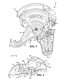
- FIG. 1 is an exploded view of a parking brake actuator
- FIG. 2 is an enlarged view of a portion of the exploded view of FIG. 1 ;
- FIG. 3 is an assembled side view of the parking brake actuator shown in FIG. 1 ;
- FIG. 4 is a side view of a pawl
- FIG. 5 is a side view of a release flipper
- FIG. 6 is a perspective view of a control mechanism that includes the pawl and flipper of FIGS. 4 and 5 ;
- FIG. 7 is a sectional view of the control mechanism shown in FIG. 6 ;
- FIG. 8 is a partial sectional view of the parking brake actuator in an initial, brake-released position
- FIG. 9 is an enlarged view of the partial sectional view shown in FIG. 8 , a head of a rivet shown in phantom to illustrate the position of the pawl relative to a rivet shaft;
- FIG. 10 is a partial sectional view of the parking brake actuator where a sector has been rotated partially counterclockwise with respect to the pawl;
- FIG. 11 is a partial sectional view of the parking brake actuator where the sector has been rotated farther counterclockwise than shown in FIG. 10 and a hook of the pawl is between two teeth of the sector in a partial brake-applied position;
- FIG. 12 is a partial sectional view of the parking brake actuator where the hook of the pawl has shifted between the two teeth of the sector and the pawl has shifted with respect to the rivet shaft into a full brake-applied position;
- FIG. 13 is an enlarged view of the partial sectional view shown in FIG. 12 , the rivet head shown in phantom to illustrate the position of the pawl relative to the rivet shaft;
- FIG. 14 is a partial sectional view of the parking brake actuator where the hook of the pawl is freed from the sector and the sector has rotated counterclockwise about the rivet shaft;
- FIG. 15 is a partial sectional view of the parking brake actuator where a bumper coupled to the sector drives the pawl counterclockwise toward the initial position of the pawl shown in FIG. 8 ;
- FIG. 16 is a side view of another embodiment of the flipper shown in FIGS. 5 ;
- FIG. 17 is an enlarged perspective view of a portion of the parking brake actuator shown in FIG. 1 having an embodiment of the control mechanism that includes the flipper of FIG. 16 .
- FIG. 1 shows an exploded view of a parking brake actuator 10 for a vehicle such as a passenger car, sport utility vehicle (SUV), pick-up truck, or the like.
- the parking brake actuator 10 enables a vehicle user to engage a vehicle wheel brake mechanism by pushing an actuator (shown as a lever) and then to later disengage the brake mechanism by pushing the lever again. While the lever in the illustrated embodiment is designed to be foot-actuated, it should be appreciated that this is merely an example.
- FIGS. 1-3 illustrate one implementation of the parking brake actuator 10 which may include a mount or support 12 , a pedal assembly 14 carried by the support 12 , a control cable 16 ( FIG. 3 only), and a control mechanism 20 carried by the support 12 .
- the illustrated support 12 is a two-part assembly having a first bracket 22 and a second bracket 24 secured together and supporting the pedal assembly 14 therebetween. Both first and second brackets 22 , 24 may include pivot holes 28 along a pivot axis P that are sized to receive one or more bushings and axle components 30 for carrying the pedal assembly 14 .
- Support 12 is also provided with suitable features 32 for securing the support to a vehicle support structure (not shown) adjacent, e.g., the driver's position in the vehicle.
- first bracket 22 has a travel stop 34 adapted to limit rotation of the control mechanism 20 , as will be explained in greater detail below.
- the stop 34 is shown as a tab extending outwardly of the first bracket 22 toward the second bracket 24 ; however, this is merely an example.
- the first bracket 22 may have a rivet hole 36 for carrying the control mechanism 20 ( FIG. 1 only).
- the support 12 enables the actuator 10 to be provided as a self-contained unit that may be readily incorporated into a vehicle. At least portions of the support 12 could be provided in the vehicle directly, such as on or being defined by existing vehicle structures.
- Pedal assembly 14 comprises a first bracket 40 , a second bracket 42 , and a self-adjust mechanism 44 , as best shown in FIG. 1 .
- First and second brackets 40 , 42 also include pivot holes 46 along pivot axis P which are sized to receive the one or more of the bushings and axle components 30 .
- first bracket 40 includes an actuator or lever 48 extending radially outwardly to a pedal pad 50 for foot-actuation by the vehicle user (e.g., driver of the vehicle).
- Second bracket 42 may include a bumper 52 which is adapted to initiate a resetting of the control mechanism 20 , which will be explained in greater detail below (see FIGS. 1 and 3 ).
- second bracket 42 includes an engagement member 54 (shown as a sector) which is fixedly coupled thereto.
- Sector 54 may have a curved row of ratchet teeth 60 extending along a portion of a peripheral edge 62 (see FIG. 3 ). More specifically, sector 54 is oriented so that ratchet teeth 60 are disposed circumferentially or arcuately relative to pivot axis P. While engagement member 54 is illustrated as a sector, it should be appreciated that this is merely an example and that other engagement member embodiments are contemplated (e.g., having different shapes, sizes, or both).
- Self-adjust mechanism 44 of pedal assembly 14 includes a drum and track assembly 70 , a clock spring 72 , and a torsion or clutch spring 74 , as shown in FIG. 1 .
- Drum and track assembly 70 may be coupled to one end of control cable 16 ( FIG. 3 only), and spring 74 may place the control cable 16 under a predetermined preload (tension).
- Clock spring 72 is adapted to automatically take up any slack in cable 16 (i.e., self-adjust). In this manner, self-adjust mechanisms 44 do not require re-tensioning of cable 16 at a later time. This may be desirable if the cable 16 becomes stretched or worn; and in some instances, manufacturing tolerances (e.g., due to stack up) may be relaxed due to the self-adjusting nature of the mechanism 44 .
- Control cable 16 is coupled to self-adjust mechanism 44 through a sleeve 76 , as shown in FIG. 3 .
- a distal end of the control cable 16 (not shown) is operably connected to the wheel brake mechanism (not shown). Hence, pulling the cable 16 causes the wheel brake mechanism to be applied.
- FIG. 3 illustrates an initial brake-released position of the parking brake actuator 10 . From this position, pedal assembly 14 can be rotated counterclockwise via force on pedal pad 50 —ultimately engaging the control mechanism 20 with sector 54 which rotates with the pedal assembly 14 (this engagement will be explained in greater detail below).
- the control mechanism 20 may include a coupler 80 (illustrated as a rivet), a biasing member 82 (illustrated as a spring), a retention member 84 (illustrated as a pawl), and a release actuator 86 (illustrated as a flipper).
- Rivet 80 has a longitudinally extending shaft 88 (along a rivet axis R), the shaft 88 having a narrow end 90 adapted to be received in the rivet hole 36 of the bracket 22 ( FIG. 1 ) and defining a shoulder 91 adapted to engage the bracket 22 (see also sectional view of FIG. 7 ).
- rivet 80 may have a cap or head 94 having a larger diameter than the shaft 88 .
- Rivet head 94 in at least one embodiment, has a void 96 in a portion of the head 94 that extends radially inwardly from an outer edge 98 of the head 94 and at least partially defines a first stop surface 100 and a second stop surface 102 spaced from one another by an angle (a) with respect to rivet axis R.
- Other embodiments of rivet head 94 also exist.
- void 96 is optional.
- Spring 82 may be any suitable spring for mechanically coupling the pawl 84 and flipper 86 and biasing them with respect to one another (e.g., so that the pawl 84 is responsive to movements of the flipper 86 , or vice-versa).
- spring 82 is a torsion spring comprising a coil 106 , a first leg 108 associated with and/or acting on the pawl 84 , and a second leg 110 associated with and/or acting on the flipper 86 .
- the strength of spring 82 may vary depending upon the amount of flexure of legs 108 , 110 (during operation) and the characteristics of spring 82 (e.g., material, diameter of legs 108 , 110 , length of legs 108 , 110 , etc.).
- Pawl 84 may have an elongated, planar body 112 having a head 114 at one end 116 and a tail 118 at an opposite end 120 ( FIGS. 2 and 4 ). Pawl 84 may have a tooth or hook 122 sized and shaped to engage the teeth 60 of sector 54 ; e.g., located nearer head 114 . Tail 118 may include a coupling region 124 sized to receive leg 108 of spring 82 . Coupling region 124 is illustrated as through-hole; however, this is merely an example—other implementations are possible.
- pawl 84 may have an axially extending ridge 126 on one face 128 ; it also may have a rivet opening 130 between the ridge 126 and tail 118 which opening extends through the body 112 .
- ridge 126 may have a shoulder or driving member 134 radially extending from the ridge 126 toward rivet opening 130 .
- driving member 134 also exist; e.g., driving member 134 could be any other structure axially extending from face 128 , such as a pin or post.
- Rivet opening 130 may be sized to receive the rivet shaft 88 therethrough. More particularly, it may be larger than the rivet shaft 88 and may be defined by an elongated slot to permit movement of pawl 84 relative to the rivet 80 .
- the slot 130 may be smaller in one dimension than another dimension to permit rotation of the pawl 84 relative to the coupler and to permit translation of the pawl 84 relative to the coupler.
- slot 130 has a width (w) closely matched to the shaft 88 diameter and a length (l) greater than the shaft 88 diameter so that pawl 84 may move relative to the rivet 80 in the length (l) direction of the slot (and move less, or not at all, in the width (w) direction of the slot).
- the length (l) of the slot 130 may be defined by the spacing between a first end 131 (nearer the head 114 ) and a second end 132 (nearer the tail 118 ).
- the position of opening 130 (e.g., between hook 122 and coupling region 124 ) and orientation of the elongation enables pawl 84 , during operation of actuator 10 , to move within opening 130 and/or pivot about opening 130 as spring 82 forces act on hook 122 and coupling region 124 , as will be described in detail later.
- the position of rivet opening 130 and coupling region 124 may have a predefined relationship.
- rivet opening 130 is shown with a reference line A passing through the first and second ends 131 , 132 and the first and second locus points L 1 , L 2 , where first locus point L 1 is nearer the head 114 (and driving member 134 ) and where second locus point L 2 is nearer the tail 118 .
- locus point L 1 may be a position generally coincident with axis R when rivet shaft 88 abuts the first end 131 .
- locus point L 2 may be a position generally coincident with axis R when rivet shaft 88 abuts the second ends 132 (see e.g., FIGS. 9 and 13 ).
- Pawl 84 may be manufactured from any suitably rigid and durable material(s).
- pawl 84 includes a two-piece construction of a metal and a rubber or a plastic.
- pawl 84 may have metal at locations contacted by other components such the rivet 80 and sector 54 .
- Other portions may have a plastic sleeve or be plastic-coated. This of course is merely one example; other single- and multi-piece implementations are contemplated also.
- flipper 86 may include a body 150 having a coupling end 152 and a free end 156 .
- Coupling end 152 has a partially, circumferentially extending counterbore surface 160 around a through-hole 166 which is closely matched to the diameter of rivet shaft 88 .
- a feature or projection 168 is shown extending axially away from the counterbore surface 160 and also extending radially away from opening 166 towards free end 156 .
- Projection 168 is designed to cooperate with travel stop surfaces 100 , 102 of rivet head 94 (as discussed below).
- a driven surface 172 of flipper 86 may be located at one side 170 of flipper 86 and may extend at least a portion of the length between coupling end 152 and axis R (which passes through opening 166 , FIG. 5 ). When control mechanism 20 is assembled and operated, driven surface 172 may be positioned to interact with driving member 134 of pawl 84 , as will be explained more below.
- Free end 156 of flipper 86 includes a coupling region 186 arranged to receive the leg 110 of spring 82 .
- Coupling region 186 may be located between the free end 156 and axis R.
- driven surface 172 and coupling region 186 may be on opposing sides of axis R.
- Coupling region 186 is illustrated as a through-hole; however, this is not required.
- coupling region 186 , projection 168 , and the rivet axis R (and through-hole 166 ) are aligned radially; however, other implementations also may be used.
- FIGS. 6-7 illustrate an assembled control mechanism 20 .
- Rivet shaft 88 may be received through rivet hole 166 of flipper 86 , through rivet opening 130 of pawl 84 , and into rivet hole 36 of first bracket 22 .
- the end 90 of shaft 88 may be located in rivet hole 36 while shoulder 91 abuts the region about hole 36 on first bracket 22 ( FIG. 7 ).
- flipper 86 and pawl 84 may be captured between the first bracket 22 and rivet head 94 .
- pawl 84 may be positioned between the first bracket 22 and flipper 86
- flipper 86 may be positioned between pawl 84 and rivet head 94 .
- Rivet head 94 may be received adjacent to the counterbore surface 160 , and projection 168 may be located within void 96 and pivotal motion of flipper 86 relative to the rivet 80 may be limited in accordance with angle (a) between the travel stop surfaces 100 , 102 .
- Leg 108 of spring 82 may be located in coupling region 124 of pawl 84 ; leg 110 of spring 82 may be located in coupling region 186 of flipper 86 —and when assembled, control mechanism 20 is located in actuator 10 , the pawl 84 and flipper 86 may be oriented with respect to one another so that legs 108 , 110 are biased away from one another.
- spring 82 (as well as other structures) may act upon pawl 84 and flipper 86 to rotate the pawl and flipper relative to rivet 80 and slide the pawl relative thereto.
- pawl 84 and flipper 86 may be yieldably biased into the path of movement of the sector 54 (carried by pedal assembly 14 ).
- pawl 84 may engage sector 54 .
- the flipper 86 and pawl 84 may be driven to a second position wherein the pawl 84 is yieldably biased by the spring 82 out of the path of the sector 54 so that when the pedal assembly 14 is released from the brake-applied position, the pawl 84 is displaced out of the sector's path thereby allowing the sector to return to the initial parking brake-released position. While the pedal assembly and sector 54 return to the initial brake-applied position, pawl 84 may be returned to the first position—thus, the assembly may be ready for the parking brake to be re-applied.
- pedal assembly 14 rotates counterclockwise about pivot axis P from the initial parking brake-released position to the parking brake-applied position.
- pawl 84 engages the sector 54 .
- the pawl 84 is automatically disengaged from the sector 54 enabling cable tension to rotate pedal assembly 14 clockwise and return it to the initial brake-released position.
- FIG. 8 shows a partial sectional view of parking brake actuator 10 illustrating the initial brake-released position.
- the hook 122 of pawl 84 is not engaged with any teeth 60 of the sector 54
- pawl 84 is oriented about the rivet shaft 88 so that head 114 is yieldably biased toward sector 54 .
- Rivet 80 abuts end 132 in opening 130 (e.g., rivet axis R may be coincident with locus point L 2 ) (see also FIG. 9 ).
- flipper projection 168 may be between rivet head stops 100 , 102 , and spring legs 108 , 110 may not being flexed or otherwise biased outwardly (e.g., may be at rest).
- FIG. 8 also illustrates a plane X which may be defined by axis R of rivet 80 and a contact point 190 between spring leg 110 and flipper 86 .
- contact point 190 may shift or move within region 186 considerably (e.g., depending on relative positions of the pawl 84 and flipper 86 , as well as the size of coupling region 186 ).
- a second contact point 192 associated with spring leg 108 and coupling region 124 of pawl 84 is illustrated as well. When the second contact point 192 is on one side of plane X (as shown in FIG. 8 ), pawl 84 is urged counterclockwise.
- pawl 84 may be urged clockwise.
- a reference line B (defined by contact points 190 , 192 ) is shown intersecting plane X at an angle ( ⁇ ), and when angle ( ⁇ ) is positive (as it is in FIG. 8 ), pawl 84 is urged counterclockwise.
- Pawl 84 and flipper 86 may remain in the position shown in FIG. 8 until the pedal assembly 14 is rotated about pivot P to actuate the wheel brake mechanism.
- pedal assembly 14 has been rotated at least partially counterclockwise from the brake-released position toward the brake-applied position.
- sector 54 has engaged the pawl 84 and rotated the pawl clockwise against the force of spring 82 .
- Hook 122 is shown here to be touching a tip of one of the plurality of ratchet teeth 60 .
- the flipper 86 also is rotated clockwise by the force of spring 82 until projection 168 of flipper 86 engages the second travel stop 102 of rivet 80 which prevents further clockwise rotation of flipper 86 .
- FIG. 11 pedal assembly 14 (and sector 54 which is connected thereto) has been rotated further counterclockwise, and hook 122 is received between two of the ratchet teeth 60 .
- FIG. 11 is otherwise generally similar to FIG. 10 and illustrates a moment in time before the counterclockwise force being applied to the sector 54 and pedal assembly 14 is released (e.g., by the user releasing the pedal pad 50 ) In this position, the pawl 84 is still urged counterclockwise toward the sector 54 .
- the suitably large value of the angle ( ⁇ ) may account for manufacturing tolerances of one or more components of brake actuator 10 (e.g., and their respective stack up).
- the pawl 84 is biased away from sector 54 but such movement is prevented by engagement of hook 122 with a tooth 60 of sector 54 .
- pawl 84 will rotate clockwise about rivet 80 and move away from the sector 54 so that the control mechanism 20 does not interfere with the sector 54 as the sector returns to its initial brake-released position.
- pedal assembly 14 has been rotated at least partially counterclockwise from the brake-applied position to release the wheel brake mechanism (e.g., a push-to-release).
- the wheel brake mechanism e.g., a push-to-release.
- cable tension e.g., the force F S which was shown in FIG. 12
- pawl 84 rotates clockwise as urged by the spring 82 until pawl 84 engages the stop 34 .
- Counterclockwise rotation of flipper 86 is prevented as projection 168 abuts stop 100 on rivet 80 .
- force F still tends to rotate pawl 84 clockwise (the angle ( ⁇ ) may remain negative).
- pawl 84 remains in a position where the first slot end 131 engages the rivet shaft 88 (e.g., where axis R coincides with locus point L 1 , as shown in FIG. 13 ).
- pedal assembly 14 has rotated clockwise to the initial brake-released position (e.g., in response to control cable 16 tension).
- bumper 52 (on first bracket 40 ) of pedal assembly 14 engages the head 114 of pawl 84 and rotates pawl 84 counterclockwise thereby resetting the pawl 84 to its starting position, which is the position that the pawl 84 was in when the assembly was in the initial brake-released position.
- leg 108 of spring 82 also displaces so that second contact point 192 crosses over plane X, once again biasing pawl 84 in a counterclockwise direction (and angle ( ⁇ ) is again positive).
- the spring force F also slides the pawl 84 relative to rivet 80 so that rivet shaft 88 engages the pawl at the second end 132 of opening 130 (e.g., where axis R coincides with locus point L 2 , as shown in FIG. 9 ).
- the flipper 86 too may return to its starting position, being located between stops 100 , 102 . Therefore, the control mechanism 20 and pedal assembly 14 have been reset to their starting positions and the process previously described (and shown in FIGS. 8-15 ) may be repeated as desired.
- end 116 of head 114 may touch or contact sector 54 (e.g., in a region without teeth) in the initial brake-applied position.
- whether end 116 contacts sector 54 in the initial brake-released position is a function of the orientation of and magnitude of the forces acting on the control mechanism (e.g. the spring force, friction, location or stop surfaces).
- the spring 82 may urge the pawl 84 toward sector 54 in the starting position.
- the spring 82 is shown biasing the pawl 84 neither clockwise nor counterclockwise; however, this is not required.
- spring 82 may urge the pawl 84 counterclockwise in the starting position.
- FIGS. 16 and 17 illustrate a different flipper 86 ′ and a pair of flanges 200 , 202 which are adapted to limit movement of flipper 86 ′ and which may be integral to first bracket 22 , (here, like reference numerals represent similar or like features or functions).
- a free end 156 ′ of flipper 86 ′ is spaced farther from coupling end 152 ′ (than that shown in FIG. 5 ), and flipper 86 ′ has no projection 168 (as shown in FIG. 5 ).
- the spacing between opening 166 ′ and coupling region 186 ′ may be the same so that the torsional spring force F may act similarly to that described in FIGS. 8-15 .
- the extra radially-extending length of free end 156 ′ may be operable with the flanges 200 , 202 .
- FIG. 17 illustrates an enlarged portion of one embodiment of the first bracket 22 .
- Flanges 200 , 202 are shown as tabs extending outwardly of first bracket 22 (toward second bracket 24 ).
- Flanges 200 , 202 have inwardly facing travel stops or stop surfaces 210 , 212 , respectively.
- the spacing between stop surfaces 210 , 212 may allow the width of the free end 156 ′ of flipper 86 ′ to move angularly therebetween.
- Other flange implementations are contemplated also.
- flanges 200 , 202 may function to limit the travel of flipper 86 ′, having a function similar to stops 100 , 102 described above.
- free end 156 ′ of flipper 86 ′ may travel across angular range ( ⁇ ), as described above.
- head 94 ′ of rivet 80 ′ ( FIG. 17 ) need not have the void 96 or stops 100 , 102 , as described above.
- the parking brake actuator for a wheel brake mechanism of a vehicle.
- the parking brake actuator is foot-operated enabling a vehicle user to depress a pedal pad to engage the brake mechanism, and then later depress the pedal pad again to release the brake mechanism.
- the parking brake actuator reciprocates between a brake-released position and a brake-applied position in repeated actuations of the brake actuator.
- the brake actuator includes an engagement member, a retention member, and an actuator. The retention member and actuator are acted upon by a biasing member that so that the retention member engages and automatically disengages from the engagement member to permit repeated and reliable actuation and release of the vehicle parking brake and repeatable resetting of the assembly for subsequent cycles.
Abstract
Description
Claims (20)
Priority Applications (1)
| Application Number | Priority Date | Filing Date | Title |
|---|---|---|---|
| US14/789,222 US9845083B2 (en) | 2015-07-01 | 2015-07-01 | Park brake control assembly |
Applications Claiming Priority (1)
| Application Number | Priority Date | Filing Date | Title |
|---|---|---|---|
| US14/789,222 US9845083B2 (en) | 2015-07-01 | 2015-07-01 | Park brake control assembly |
Publications (2)
| Publication Number | Publication Date |
|---|---|
| US20170001605A1 US20170001605A1 (en) | 2017-01-05 |
| US9845083B2 true US9845083B2 (en) | 2017-12-19 |
Family
ID=57682870
Family Applications (1)
| Application Number | Title | Priority Date | Filing Date |
|---|---|---|---|
| US14/789,222 Active 2036-02-01 US9845083B2 (en) | 2015-07-01 | 2015-07-01 | Park brake control assembly |
Country Status (1)
| Country | Link |
|---|---|
| US (1) | US9845083B2 (en) |
Families Citing this family (1)
| Publication number | Priority date | Publication date | Assignee | Title |
|---|---|---|---|---|
| US10183655B1 (en) * | 2017-07-21 | 2019-01-22 | Dongwoun Industrial Co., Ltd. | Monobloc mounting bracket for foot parking brake |
Citations (26)
| Publication number | Priority date | Publication date | Assignee | Title |
|---|---|---|---|---|
| US4391159A (en) * | 1980-12-03 | 1983-07-05 | Gulf & Western Manufacturing Company | Parking brake actuating device |
| US4841798A (en) * | 1988-08-30 | 1989-06-27 | Orscheln Co. | Foot-operated self-adjusting parking brake apparatus with controlled flyback |
| US4872368A (en) * | 1988-07-28 | 1989-10-10 | Orscheln Co. | Push-to-release cable operating apparatus |
| US5211072A (en) * | 1990-07-26 | 1993-05-18 | Dura Mechanical Components, Inc. | Variable ratio park brake with slack adjust |
| US5217094A (en) | 1991-08-09 | 1993-06-08 | Atwood Industries, Inc. | Self-adjusting, push-to-release parking brake control |
| US5235867A (en) * | 1991-10-10 | 1993-08-17 | Orscheln Co. | Lockout means for cable tension adjustment |
| US5309786A (en) * | 1993-03-08 | 1994-05-10 | Dura Mechanical Components, Inc. | Self-adjusting parking brake actuator |
| US5467666A (en) | 1994-07-07 | 1995-11-21 | Dura Automotive Systems, Inc. | Non-jamming self-adjust pawl and ratchet mechanism |
| US5533420A (en) * | 1994-05-20 | 1996-07-09 | Dura Automotive Holding, Inc. | Parking brake system including an internal clutch spring |
| US5588335A (en) | 1995-04-28 | 1996-12-31 | Strait; Daniel L. | Torsion lock parking brake actuator with push down release |
| US5775174A (en) | 1995-07-20 | 1998-07-07 | Aisin Seiki Kabushiki Kaisha | Vehicular foot-operated parking brake control apparatus |
| US6736025B2 (en) * | 2000-11-21 | 2004-05-18 | Aisin Seiki Kabushiki Kaisha | Vehicular foot-operated parking brake control apparatus |
| US6837127B2 (en) * | 2000-06-16 | 2005-01-04 | Edscha Ag | Parking brake |
| US20070068317A1 (en) * | 2005-08-12 | 2007-03-29 | Krupin Vladimir G | Ratchet-type parking brake having quiet operation |
| US20070227290A1 (en) | 2006-04-04 | 2007-10-04 | Ferenc Anthony S | Pull-to-release hand brake |
| US20070227288A1 (en) * | 2006-03-14 | 2007-10-04 | Ferenc Anthony S | Push-to-release foot brake with eccentric torsion-lock self adjust mechanism |
| US7337694B2 (en) * | 2004-10-13 | 2008-03-04 | Advics Co., Ltd. | Foot-operated parking brake device for vehicles |
| US7472624B2 (en) * | 2004-07-07 | 2009-01-06 | Ventra Group Inc. | Push to release brake actuating assembly for a vehicle |
| US7574943B2 (en) | 2005-06-01 | 2009-08-18 | Dura Global Technologies, Inc. | Parking brake actuator with clutch spring assembly |
| US7584684B2 (en) * | 2004-05-12 | 2009-09-08 | Honda Giken Kogyo Kabushiki Kaisha | Man-powered braking apparatus |
| US8025129B2 (en) * | 2008-01-25 | 2011-09-27 | Schaeffler Kg | Overrunning clutch parking brake actuator |
| US8113086B2 (en) * | 2007-03-26 | 2012-02-14 | Dura Global Technologies, Llc | Parking brake with separate pedal pivot |
| US8245596B2 (en) * | 2006-11-22 | 2012-08-21 | Dura Global Technologies, Llc | Parking brake |
| US9139169B2 (en) * | 2006-08-18 | 2015-09-22 | Dura Operating Llc | Release mechanism for a parking brake clutch |
| US9278671B2 (en) * | 2012-02-01 | 2016-03-08 | Toyoda Iron Works Co., Ltd. | Parking brake device |
| US9487192B2 (en) * | 2012-11-26 | 2016-11-08 | Honda Motor Co., Ltd. | Parking brake device |
-
2015
- 2015-07-01 US US14/789,222 patent/US9845083B2/en active Active
Patent Citations (27)
| Publication number | Priority date | Publication date | Assignee | Title |
|---|---|---|---|---|
| US4391159A (en) * | 1980-12-03 | 1983-07-05 | Gulf & Western Manufacturing Company | Parking brake actuating device |
| US4872368A (en) * | 1988-07-28 | 1989-10-10 | Orscheln Co. | Push-to-release cable operating apparatus |
| US4841798A (en) * | 1988-08-30 | 1989-06-27 | Orscheln Co. | Foot-operated self-adjusting parking brake apparatus with controlled flyback |
| US5211072A (en) * | 1990-07-26 | 1993-05-18 | Dura Mechanical Components, Inc. | Variable ratio park brake with slack adjust |
| US5217094A (en) | 1991-08-09 | 1993-06-08 | Atwood Industries, Inc. | Self-adjusting, push-to-release parking brake control |
| US5235867A (en) * | 1991-10-10 | 1993-08-17 | Orscheln Co. | Lockout means for cable tension adjustment |
| US5309786A (en) * | 1993-03-08 | 1994-05-10 | Dura Mechanical Components, Inc. | Self-adjusting parking brake actuator |
| US5533420A (en) * | 1994-05-20 | 1996-07-09 | Dura Automotive Holding, Inc. | Parking brake system including an internal clutch spring |
| US5467666A (en) | 1994-07-07 | 1995-11-21 | Dura Automotive Systems, Inc. | Non-jamming self-adjust pawl and ratchet mechanism |
| US5588335A (en) | 1995-04-28 | 1996-12-31 | Strait; Daniel L. | Torsion lock parking brake actuator with push down release |
| US5775174A (en) | 1995-07-20 | 1998-07-07 | Aisin Seiki Kabushiki Kaisha | Vehicular foot-operated parking brake control apparatus |
| US6837127B2 (en) * | 2000-06-16 | 2005-01-04 | Edscha Ag | Parking brake |
| US6736025B2 (en) * | 2000-11-21 | 2004-05-18 | Aisin Seiki Kabushiki Kaisha | Vehicular foot-operated parking brake control apparatus |
| US7584684B2 (en) * | 2004-05-12 | 2009-09-08 | Honda Giken Kogyo Kabushiki Kaisha | Man-powered braking apparatus |
| US7472624B2 (en) * | 2004-07-07 | 2009-01-06 | Ventra Group Inc. | Push to release brake actuating assembly for a vehicle |
| US7337694B2 (en) * | 2004-10-13 | 2008-03-04 | Advics Co., Ltd. | Foot-operated parking brake device for vehicles |
| US7574943B2 (en) | 2005-06-01 | 2009-08-18 | Dura Global Technologies, Inc. | Parking brake actuator with clutch spring assembly |
| US20070068317A1 (en) * | 2005-08-12 | 2007-03-29 | Krupin Vladimir G | Ratchet-type parking brake having quiet operation |
| US20070227288A1 (en) * | 2006-03-14 | 2007-10-04 | Ferenc Anthony S | Push-to-release foot brake with eccentric torsion-lock self adjust mechanism |
| US20070227290A1 (en) | 2006-04-04 | 2007-10-04 | Ferenc Anthony S | Pull-to-release hand brake |
| US9139169B2 (en) * | 2006-08-18 | 2015-09-22 | Dura Operating Llc | Release mechanism for a parking brake clutch |
| US8245596B2 (en) * | 2006-11-22 | 2012-08-21 | Dura Global Technologies, Llc | Parking brake |
| US8707819B2 (en) | 2006-11-22 | 2014-04-29 | Dura Operating Llc | Parking brake |
| US8113086B2 (en) * | 2007-03-26 | 2012-02-14 | Dura Global Technologies, Llc | Parking brake with separate pedal pivot |
| US8025129B2 (en) * | 2008-01-25 | 2011-09-27 | Schaeffler Kg | Overrunning clutch parking brake actuator |
| US9278671B2 (en) * | 2012-02-01 | 2016-03-08 | Toyoda Iron Works Co., Ltd. | Parking brake device |
| US9487192B2 (en) * | 2012-11-26 | 2016-11-08 | Honda Motor Co., Ltd. | Parking brake device |
Also Published As
| Publication number | Publication date |
|---|---|
| US20170001605A1 (en) | 2017-01-05 |
Similar Documents
| Publication | Publication Date | Title |
|---|---|---|
| US7472624B2 (en) | Push to release brake actuating assembly for a vehicle | |
| US6142036A (en) | Brake pedal apparatus for vehicle | |
| EP1752347B1 (en) | Ratchet type parking brake having quiet operation | |
| US7574943B2 (en) | Parking brake actuator with clutch spring assembly | |
| US4385529A (en) | Foot-operated parking brake lever assembly | |
| US9845083B2 (en) | Park brake control assembly | |
| US7181991B2 (en) | Automobile accelerator and brake pedal device | |
| US5054333A (en) | Movable pedal lever stop | |
| WO2018186368A1 (en) | Device for cancelling erroneous operation of accelerator pedal | |
| JP4700039B2 (en) | Parking brake device | |
| US8113086B2 (en) | Parking brake with separate pedal pivot | |
| JP6765112B2 (en) | Foot-operated parking brake device | |
| JPS5826858Y2 (en) | Automobile parking brake control device | |
| US20030015380A1 (en) | Brake actuator with one-piece take-up reel | |
| US5997438A (en) | Combination control for vehicles | |
| JP2020128187A (en) | Lever device of parking brake | |
| JP2761024B2 (en) | Foot-operated parking brake device | |
| JPH0123877Y2 (en) | ||
| US20090101455A1 (en) | Self-adjusting torsion lock parking brake | |
| JP2008157284A (en) | Parking lever retention mechanism for drum brake | |
| JPH0613974U (en) | Parking brake device | |
| KR970004579Y1 (en) | Brake holder linkaged accelerator | |
| JPS6333727Y2 (en) | ||
| JP2018028758A (en) | Pedal operation mechanism | |
| CN116442964A (en) | Brake pedal resetting mechanism, brake pedal assembly and vehicle |
Legal Events
| Date | Code | Title | Description |
|---|---|---|---|
| AS | Assignment |
Owner name: DURA OPERATING, LLC, MICHIGAN Free format text: ASSIGNMENT OF ASSIGNORS INTEREST;ASSIGNORS:HENCK, JEREMY M.;STEAKLEY, BRIAN E.;SIGNING DATES FROM 20151119 TO 20151120;REEL/FRAME:037134/0932 |
|
| STCF | Information on status: patent grant |
Free format text: PATENTED CASE |
|
| AS | Assignment |
Owner name: FLOW INTERNATIONAL CORPORATION, WASHINGTON Free format text: RELEASE BY SECURED PARTY;ASSIGNOR:ALLY BANK;REEL/FRAME:047829/0140 Effective date: 20180420 Owner name: KMT ROBOTIC SOLUTIONS, INC., KANSAS Free format text: RELEASE BY SECURED PARTY;ASSIGNOR:ALLY BANK;REEL/FRAME:047829/0140 Effective date: 20180420 Owner name: H2O JET, INC., WASHINGTON Free format text: RELEASE BY SECURED PARTY;ASSIGNOR:ALLY BANK;REEL/FRAME:047829/0140 Effective date: 20180420 Owner name: SHAPE TECHNOLOGIES GROUP, INC., KANSAS Free format text: RELEASE BY SECURED PARTY;ASSIGNOR:ALLY BANK;REEL/FRAME:047829/0140 Effective date: 20180420 |
|
| AS | Assignment |
Owner name: DUS OPERATING INC., MICHIGAN Free format text: ASSIGNMENT OF ASSIGNORS INTEREST;ASSIGNOR:DURA OPERATING, LLC;REEL/FRAME:055131/0001 Effective date: 20200605 |
|
| AS | Assignment |
Owner name: WELLS FARGO BANK, NATIONAL ASSOCIATION, AS AGENT, ILLINOIS Free format text: SECURITY AGREEMENT;ASSIGNOR:DUS OPERATING INC.;REEL/FRAME:055228/0843 Effective date: 20210205 Owner name: BLUE TORCH FINANCE LLC, AS COLLATERAL AGENT, NEW YORK Free format text: PATENT AND TRADEMARK SECURITY AGREEMENT;ASSIGNORS:DURA AUTOMOTIVE HOLDINGS U.K., LTD;DURA AUTOMOTIVE SYSTEMS GMBH;DUS OPERATING INC.;REEL/FRAME:055224/0756 Effective date: 20210205 |
|
| MAFP | Maintenance fee payment |
Free format text: PAYMENT OF MAINTENANCE FEE, 4TH YEAR, LARGE ENTITY (ORIGINAL EVENT CODE: M1551); ENTITY STATUS OF PATENT OWNER: LARGE ENTITY Year of fee payment: 4 |
|
| AS | Assignment |
Owner name: DUS OPERATING, INC., MICHIGAN Free format text: RELEASE OF PATENT AND TRADEMARK SECURITY AGREEMENT;ASSIGNOR:BLUE TORCH FINANCE LLC;REEL/FRAME:058671/0253 Effective date: 20220103 Owner name: DURA AUTOMOTIVE SYSTEMS GMBH, GERMANY Free format text: RELEASE OF PATENT AND TRADEMARK SECURITY AGREEMENT;ASSIGNOR:BLUE TORCH FINANCE LLC;REEL/FRAME:058671/0253 Effective date: 20220103 Owner name: DURA AUTOMOTIVE HOLDINGS U.K., LTD, UNITED KINGDOM Free format text: RELEASE OF PATENT AND TRADEMARK SECURITY AGREEMENT;ASSIGNOR:BLUE TORCH FINANCE LLC;REEL/FRAME:058671/0253 Effective date: 20220103 |
|
| AS | Assignment |
Owner name: BLUE TORCH FINANCE LLC, AS COLLATERAL AGENT, NEW YORK Free format text: PATENT AND TRADEMARK SECURITY AGREEMENT;ASSIGNORS:DURA AUTOMOTIVE HOLDINGS U.K., LTD;DUS OPERATING INC.;GROUPER STAMPING, LLC;AND OTHERS;REEL/FRAME:059704/0131 Effective date: 20220413 |
|
| AS | Assignment |
Owner name: DUS OPERATING INC., MICHIGAN Free format text: RELEASE BY SECURED PARTY;ASSIGNOR:WELLS FARGO BANK, NATIONAL ASSOCIATION;REEL/FRAME:059783/0288 Effective date: 20220413 |
|
| AS | Assignment |
Owner name: GROUPER ACQUISITION COMPANY, LLC, MICHIGAN Free format text: RELEASE BY SECURED PARTY;ASSIGNOR:BLUE TORCH FINANCE LLC;REEL/FRAME:064502/0136 Effective date: 20230801 Owner name: GROUPER STAMPING LLC, MICHIGAN Free format text: RELEASE BY SECURED PARTY;ASSIGNOR:BLUE TORCH FINANCE LLC;REEL/FRAME:064502/0136 Effective date: 20230801 Owner name: DUS OPERATING INC., MICHIGAN Free format text: RELEASE BY SECURED PARTY;ASSIGNOR:BLUE TORCH FINANCE LLC;REEL/FRAME:064502/0136 Effective date: 20230801 Owner name: DURA AUTOMOTIVE HOLDINGS U.K., LTD., UNITED KINGDOM Free format text: RELEASE BY SECURED PARTY;ASSIGNOR:BLUE TORCH FINANCE LLC;REEL/FRAME:064502/0136 Effective date: 20230801 |