JP3772659B2 - Induction heating cooker - Google Patents
Induction heating cooker Download PDFInfo
- Publication number
- JP3772659B2 JP3772659B2 JP2000290384A JP2000290384A JP3772659B2 JP 3772659 B2 JP3772659 B2 JP 3772659B2 JP 2000290384 A JP2000290384 A JP 2000290384A JP 2000290384 A JP2000290384 A JP 2000290384A JP 3772659 B2 JP3772659 B2 JP 3772659B2
- Authority
- JP
- Japan
- Prior art keywords
- cooking
- plate
- induction heating
- top plate
- temperature
- Prior art date
- Legal status (The legal status is an assumption and is not a legal conclusion. Google has not performed a legal analysis and makes no representation as to the accuracy of the status listed.)
- Expired - Fee Related
Links
Images
Landscapes
- Induction Heating Cooking Devices (AREA)
- Baking, Grill, Roasting (AREA)
Description
【0001】
【発明の属する技術分野】
本発明は、天板より離れて設置された調理板の温度を精度よく制御した誘導加熱調理器に関するものである。
【0002】
【従来の技術】
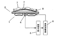
従来のこの種の一般的な誘導加熱調理器の構成図を図8に示す。図8では、調理面に凹凸を設け、凹部の溝に焼肉の油やたれが落ちて網焼きのような効果が得られる一般的な焼肉用の調理プレートを設置した例を示している。
【0003】
図8において、1は誘導加熱を行うための加熱コイル、2は加熱コイル1の上方に設置された天板であるトッププレートで、加熱コイル1から発生する磁力線を透過する耐熱性のセラミックやガラスが一般的に用いられる。3はトッププレート2に載置される溝付き焼肉プレートである。4はトッププレート2の裏面に当接して設けられた温度検知手段である。5は制御手段で、温度検知手段4によって、トッププレート2を介して測定された溝付き焼肉プレート3の温度を測定し、高周波電源6の出力を制御する。7は溝付き焼肉プレート5上に置かれた肉や野菜等の被調理物である。
【0004】
この構成において、溝付き焼肉プレート3の底面がトッププレート2に密着あるいは約1mm程度の所定の距離だけ離れて設置されている。この構成により温度調節機能が働き、たとえば温度検知手段4の検知温度が約200℃であると、溝付き焼肉プレート3の調理面の温度は約240℃であり、この相関関係により温度調節を行っている。
【0005】
また、図9は従来の他の誘導加熱調理器の構成図である。図9は、一般的な焼肉用のプレート8を利用した場合を示している。この焼き肉用のプレート8は中央部が盛り上がっており、この傾斜を利用して被調理物の油等が焼き物用のプレート周辺に溜まる構成となっている。
【0006】
【発明が解決しようとする課題】
しかしながら、前記従来の誘導加熱調理器の構成では、図8のような溝付きの焼肉プレート3を使用していると、溝にたまった焼肉のたれの焦げや油を頻繁に清掃する必要があった。
【0007】
また、図9のような中央部が盛り上がった凸状の焼肉プレート8においては、焦げの原因となる余分な焼肉のたれや油が中央から周囲に流れ落ちるため、都度調理面の清掃の手間は必要ないものの、温度検知手段4の設置されている部分が加熱している凸状の焼肉プレート8との距離が最も離れており上手く温度調節ができずに焼肉プレート8の温度が上昇し続けてしまうという問題があった。
【0008】
さらに、トッププレート2との距離が離れていると、加熱コイル1から発生する磁束が届きにくく所定の加熱熱量を得るために高周波電源の出力を上げてスイッチング素子の印加電圧を高めていく必要がある。しかし、比較的低価格のコレクタ−エミッタ間電圧(以下Vceと記す)の上限が900Vのスイッチング素子を使用すると、その保護のための制限電圧にすぐに達してしまい電圧を充分に高めることができない。そのため充分な火力が得られないという問題があった。
【0009】
本発明は前記課題を解決するもので、油受け皿を有し、トッププレートより距離を置いて設置される所定の調理板を使用した際にも、精度の良い温度調節が可能であり、かつ充分な火力が得られる誘導加熱調理器を提供することを目的とする。
【0010】
【課題を解決するための手段】
前記課題を解決するために、本発明の誘導加熱調理器は、天板上に設置して使用し中央部に周囲を壁で囲われた開口部を設けた受け皿と、誘導加熱にて加熱可能な調理板と一体となり前記開口部に挿入される導熱部とを備え、前記導熱部を前記受け皿に着脱自在に取付ける構成とした。
【0011】
これにより、天板と調理板の間に受け皿を用いながらも、受け皿の開口部に挿入され天板に当接または近接する導熱部を設けたことで、調理板の温度を天板を介して天板裏面の温度検知手段に伝えることができる。
【0012】
【発明の実施の形態】
請求項1に記載の発明は、加熱コイルおよびスイッチング素子等で構成された誘導加熱を行うための高周波電源と、前記加熱コイルの上方に設けた天板と、前記天板上に載置する誘導加熱にて加熱可能な調理板と、前記天板と前記調理板との間に設置する中央部に壁で囲われた開口部を有する受け皿と、前記被加熱物の温度を測定する温度検知手段と、前記温度検知手段の出力により前記高周波電源を制御する制御手段とを備え、前記調理板は中央部から周囲に向かって下方に傾斜し、かつ中央部に調理板の熱を前記天板に伝熱する導熱部とを有し、前記導熱部を前記開口部に着脱自在に取付けられる構成とした。
【0013】
この構成により、従来焼肉プレート上の調理面の溝にたまっていた調味液や被調理物の油分を受け皿で受けることができ、使い勝手を向上しながら、導熱部が調理板の温度を温度検知手段に伝えることができるため焼き物調理の調理性能すなわち温度調節精度を維持できる。
【0014】
請求項2に記載の発明は、特に請求項1に記載の調理板に被調理物からでた油分や調理液が滴下する孔部を設け、かつ調理板の中央から周囲に向かって下方に傾斜を設けた事により、調理物に絡んでいた余分な調味液や調理物からでた余分な油分が調理板の周囲に流れ落ち、また孔部から受け皿に滴下するため、調味液が焦げたり調理物が油にまみれたりすることなく、使い勝手と調理性能を向上することができる。
【0015】
請求項3に記載の発明は、特に請求項1に記載の受け皿の裏面にリブを設け、受け皿の底面を天板より浮かせる構成としたもので、調理板の調理面より温度の低い受け皿の温度が天板に伝達されず、すなわち導熱部の温度が天板に吸収される量を押さえることができるため、より正確に調理面の温度を温度検知手段に伝えることができる。
【0016】
【実施例】
以下、その実施例を図面を参照して説明する。なお、従来例と同一構成には同一符号を付しその説明は省略する。
【0017】
(実施例1)
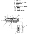
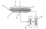
図1は本発明の第1の実施例における誘導加熱調理器の構成図である。
【0018】
図1において、1は誘導加熱を行うための加熱コイル、5は制御手段で、温度検知手段4によって、天板であるトッププレート2を介して測定された調理板としての焼き肉プレート9の温度を測定し、高周波電源6の出力を制御する。
【0019】
焼き肉プレート9は、肉や野菜等を加熱する調理面10と中央部の裏面から下方に向かって設けた磁気誘導の影響を受けない材料からなる導熱部11とが一体となって構成されている。12は受け皿で、トッププレート2の上に設置して使用する。この受け皿12の中央部には貫通部13が設けられ、この貫通部13は焼き肉プレート9の導熱部11が挿入可能な大きさとなっている。また、受け皿12の外周と貫通部13の周囲には壁が設けられ、受け皿12の上に設置された焼き肉プレート9上の調理面10から調理物の油分や調味液がトッププレート2上に流れ落ちない構成としている。
【0020】
この構成において加熱を開始すると、焼き肉プレート9の温度は誘導加熱により最初は調理面10が上昇し、次にその温度により導熱部11の温度が上昇する。導熱部11は、受け皿12の貫通部13を通ってトッププレート2に当接または近接しており、トッププレート2の裏面に当接している温度検知手段4に焼き肉プレート2の温度を伝えている。
【0021】
この導熱部11を設けたことにより、焼き肉プレート9の調理面10は温度検知手段4と離れていたとしても調理面10温度を温度検知手段4に伝達できる。
【0022】
なお本実施例では、調理板として焼き肉プレートを用いた場合について述べたがこれに限定されるものではなく、調理板として導熱部を有するものであればよいのは勿論である。
【0023】
また、本実施例では調理面と導熱部とが一体になっている場合を説明したが、調理面と導熱部とが別々になっていてもよい。この場合は調理面と導熱部とを組合わせたとき、調理面と導熱部との間に熱抵抗が生じないように注意する必要がある。
【0024】
(実施例2)
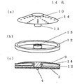
図2(a)は、本発明の第2の実施例における誘導加熱調理器の焼き肉プレートの斜視図であり、図2(b)は同誘導加熱調理器の受け皿の斜視図である。また、図2(c)は同誘導加熱調理器の断面図である。
【0025】
図において、焼き肉プレート9の調理面10に多数の孔を設け、且つ、中央からプレートの外周に向かって下方に向かう傾斜を設けている。
【0026】
これにより、調理物の油分や調味液が加熱している調理物の周辺にとどまることなく受け皿に滴下する。
【0027】
(実施例3)
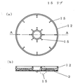
図3(a)は本発明の第3の実施例における誘導加熱調理器の受け皿の裏面図であり、図3(b)は図3(a)のA−A線断面図である。
【0028】
図3において、受け皿12の底面裏側に放射状にリブ15を設け、トッププレート2と受け皿12との間に隙間を設けている。これにより、導熱部11よりも温度の低い受け皿がトッププレート2の熱を奪い、トッププレート2の温度を下げるのを防いでいるので、導熱部11の温度をより正しく温度検知手段4に伝えることができる。
【0029】
(実施例4)
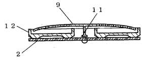
図4は本発明の第4の実施例における誘導加熱調理器の断面図である。
【0030】
図4において、導熱部11を焼き肉プレート9の肉厚よりも薄肉にしている。これにより、導熱部11の熱容量を下げているため、導熱部11の温度が調理面の温度に素早く追従する。すなわち、調理面の温度が素早く温度検知手段4に伝達される。
【0031】
なお、導熱部11の熱容量を下げる手段としては導熱部11の形状を中空の筒状体としてもよい。
【0032】
(実施例5)
誘導加熱に用いられる被加熱物として種種の形状の鍋や調理板が用いられる。本実施例では、通常の鍋と本発明に関わる焼き肉プレート等の所定の調理板とを判別する判別手段に付いて述べる。
【0033】
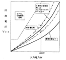
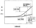
図5は本発明の第5の実施例における誘導加熱調理器入力電力とスイッチング素子のVceとの相関図であり、図6は同誘導加熱調理器のタイムチャートである。
【0034】
図5に示すように、通常の誘導加熱に適した鉄鍋では、火力が大きくなってもさほどVceが上昇しないのに比べ、本発明の所定の調理板である焼き肉プレート5や、鍋底に脚が付いていたりあるいは鍋底がへこんでいたりするためにトッププレート2から上方に離れたところに調理面10が位置する鍋では、磁束を届かせる距離が遠くなるため、よりスイッチング素子に大きな電圧がかかってしまう。したがって、所定電力値例えば1000WにおけるVce電圧を測定し、その値が所定の範囲に入っているか否かにより、通常の鍋か調理面10がトッププレート2から離なれている鍋であるかを判別できる。
【0035】
次に、図6に示すように、電力を1分間加えた後の温度上昇の違いによって、所定の調理板なのか、単に脚が付いていたりあるいは鍋底のへこみによって浮いた鍋なのかを判別できる。
【0036】
つまり、単に加熱面が浮いた鍋では、図6に示すように温度検知手段4に鍋の熱が空気を介してしか伝わらないため温度上昇がほとんどないか、あるいはかなり遅れるのにくらべ、本発明の調理板である焼肉プレート9においては、導熱部11の働きにより、調理面10の温度が直ちに温度検知手段4に伝わっている。
【0037】
このように温度上昇の傾きと、前述の入力電力とVceとの関係を合わせて、最終的に所定の調理板であるかどうかを決定できる。
【0038】
(実施例6)
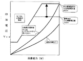
図7は本発明の第6の実施例における誘導加熱調理器の特性図である。
【0039】
通常の鍋を使用した場合には、火力が大きくなってもさほどスイッチング素子のVceが上昇しないのに比べ、本発明の所定の調理板である焼き肉プレート9や、鍋底に脚が付いていたり鍋底がへこんでいたりするためにトッププレート2から上方に離れたところに加熱面が位置する鍋は、磁束を届かせる距離が遠くなるため、Vceにより大きな電圧がかかってしまう。また、一部のステンレスにおいても、誘導加熱では発熱しにくい場合があり、この場合も通常の入力電力であってもVceに大きな電圧がかかっている。
【0040】
この様な場合には、スイッチング素子を保護するために、スイッチング素子にかかる電圧Vceを測定し所定電圧たとえば700Vを越えないように制限をしている。但しその結果として、入力電力は1000W程度になってしまう。
【0041】
このようなときに、調理板判別手段により、本発明の所定の調理板であるとわかっている場合には、このVceの制限を緩和してスイッチング素子の耐圧限界の900Vに対して、制限を850Vまでにすると、本発明の所定の調理板においても、充分な火力が得られることとなる。
【0042】
もちろん、Vceが900Vよりも高いスイッチング素子を用いてもよいが高価格になるため実用的ではなくなる。
【0043】
【発明の効果】
以上のように、請求項1ないし3に記載の発明によれば、調理板と天板との間に受け皿があるため距離が離れていたとしても、精度よく調理板の温度を制御することができる。
【図面の簡単な説明】
【図1】 本発明の第1の実施例における誘導加熱調理器の構成図
【図2】 (a)本発明の第2の実施例における誘導加熱調理器の焼き肉プレートの斜視図
(b)同誘導加熱調理器の受け皿の斜視図
(c)同誘導加熱調理器の断面図
【図3】 (a)本発明の第3の実施例における誘導加熱調理器の受け皿の裏面図
(b)図3(a)のA−A線断面図
【図4】 本発明の第4の実施例における誘導加熱調理器の断面図
【図5】 本発明の第5の実施例における誘導加熱調理器の入力電力とスイッチング素子のVceとの相関図
【図6】 本発明の第5の実施例における誘導加熱調理器のタイムチャート
【図7】 本発明の第6の実施例における誘導加熱調理器の特性図
【図8】 従来例の誘導加熱調理器の構成図
【図9】 従来例の他の誘導加熱調理器の構成図
【符号の説明】
1 加熱コイル
2 トッププレート(調理板)
4 温度検知手段
5 制御手段
6 高周波電源
7 調理物
9 焼き肉プレート(調理板)
11 導熱部
12 受け皿
13 貫通部(開口部)
14 孔
15 リブ[0001]
BACKGROUND OF THE INVENTION
The present invention relates to an induction heating cooker that accurately controls the temperature of a cooking plate installed away from a top plate.
[0002]
[Prior art]
FIG. 8 shows a configuration diagram of a conventional general induction heating cooker of this type. FIG. 8 shows an example in which a cooking plate for general yakiniku is provided in which unevenness is provided on the cooking surface and oil or sauce of yakiniku falls in the groove of the recess and an effect like grilling is obtained.
[0003]
In FIG. 8, 1 is a heating coil for performing induction heating, 2 is a top plate which is a top plate installed above the
[0004]
In this configuration, the bottom surface of the
[0005]
FIG. 9 is a configuration diagram of another conventional induction heating cooker. FIG. 9 shows a case where a
[0006]
[Problems to be solved by the invention]
However, in the configuration of the conventional induction heating cooker, if the grilled
[0007]
In addition, in the convex-shaped grilled
[0008]
Furthermore, if the distance from the
[0009]
The present invention solves the above-mentioned problem. Even when a predetermined cooking plate that has an oil pan and is installed at a distance from the top plate is used, accurate temperature adjustment is possible and sufficient. An object of the present invention is to provide an induction heating cooker that can obtain a sufficient heating power.
[0010]
[Means for Solving the Problems]
In order to solve the above-mentioned problems, the induction heating cooker of the present invention is installed on a top plate and used, and can be heated by induction heating with a tray provided with an opening surrounded by a wall at the center. And a heat conducting part that is integrated with a cooking plate and inserted into the opening, and the heat conducting part is detachably attached to the tray.
[0011]
Thereby, while using a saucer between the top plate and the cooking plate, the temperature of the cooking plate is set via the top plate by providing a heat conducting part that is inserted into the opening of the saucer and comes into contact with or close to the top plate. This can be transmitted to the temperature detection means on the back side.
[0012]
DETAILED DESCRIPTION OF THE INVENTION
The invention according to
[0013]
With this configuration, it is possible to receive in the dish the seasoning liquid and the oil content of the food to be cooked that have been accumulated in the groove of the cooking surface on the conventional grilled meat plate, and the heat conduction part detects the temperature of the cooking plate while detecting the temperature. Therefore, the cooking performance of the pottery cooking, that is, the temperature control accuracy can be maintained.
[0014]
The invention according to
[0015]
The invention according to
[0016]
【Example】
Hereinafter, the embodiment will be described with reference to the drawings. In addition, the same code | symbol is attached | subjected to the same structure as a prior art example, and the description is abbreviate | omitted.
[0017]
Example 1
FIG. 1 is a configuration diagram of an induction heating cooker according to a first embodiment of the present invention.
[0018]
In FIG. 1, 1 is a heating coil for performing induction heating, 5 is a control means, and the temperature of the grilled
[0019]
The grilled
[0020]
When heating is started in this configuration, the temperature of the grilled
[0021]
By providing the heat conducting section 11, the
[0022]
In the present embodiment, the case where the grilled meat plate is used as the cooking plate is described. However, the present invention is not limited to this, and it is needless to say that the cooking plate has a heat conducting portion.
[0023]
Moreover, although the present Example demonstrated the case where the cooking surface and the heat conducting part were united, the cooking surface and the heat conducting part may be separate. In this case, when the cooking surface and the heat conducting unit are combined, care must be taken so that no thermal resistance is generated between the cooking surface and the heat conducting unit.
[0024]
(Example 2)
Fig.2 (a) is a perspective view of the grilled meat plate of the induction heating cooking appliance in the 2nd Example of this invention, FIG.2 (b) is a perspective view of the saucer of the induction heating cooking appliance. Moreover, FIG.2 (c) is sectional drawing of the induction heating cooking appliance.
[0025]
In the figure, a large number of holes are provided in the
[0026]
Thereby, the oil content and seasoning liquid of a cooking are dripped at a saucer, without staying around the cooking which is heating.
[0027]
Example 3
Fig.3 (a) is a reverse view of the saucer of the induction heating cooking appliance in the 3rd Example of this invention, FIG.3 (b) is the sectional view on the AA line of Fig.3 (a).
[0028]
In FIG. 3, ribs 15 are provided radially on the back side of the bottom surface of the tray 12, and a gap is provided between the
[0029]
(Example 4)
FIG. 4 is a sectional view of an induction heating cooker in the fourth embodiment of the present invention.
[0030]
In FIG. 4, the heat conducting portion 11 is thinner than the thickness of the grilled
[0031]
As a means for reducing the heat capacity of the heat conducting unit 11, the shape of the heat conducting unit 11 may be a hollow cylindrical body.
[0032]
(Example 5)
Various shapes of pots and cooking plates are used as objects to be heated for induction heating. In the present embodiment, a description will be given of a discriminating means for discriminating between a normal pan and a predetermined cooking plate such as a grilled meat plate according to the present invention.
[0033]
FIG. 5 is a correlation diagram between the induction heating cooker input power and Vce of the switching element in the fifth embodiment of the present invention, and FIG. 6 is a time chart of the induction heating cooker.
[0034]
As shown in FIG. 5, in the iron pan suitable for normal induction heating, Vce does not rise so much even when the heating power increases, and the grilled
[0035]
Next, as shown in FIG. 6, it is possible to determine whether the cooking plate is a predetermined cooking plate, simply a leg, or a pan that has floated due to a dent on the bottom of the pan, depending on the difference in temperature rise after applying electric power for 1 minute. .
[0036]
That is, in the pan where the heating surface is simply floated, as shown in FIG. 6, since the heat of the pan is transmitted only to the temperature detection means 4 through the air, the temperature rise hardly occurs or is considerably delayed. In the grilled
[0037]
In this way, it is possible to determine whether or not the predetermined cooking plate is finally obtained by combining the slope of the temperature rise and the relationship between the input power and Vce described above.
[0038]
(Example 6)
FIG. 7 is a characteristic diagram of the induction heating cooker in the sixth embodiment of the present invention.
[0039]
When a normal pan is used, the Vce of the switching element does not rise so much even if the heating power increases, and the grilled
[0040]
In such a case, in order to protect the switching element, the voltage Vce applied to the switching element is measured and limited so as not to exceed a predetermined voltage, for example, 700V. However, as a result, the input power is about 1000 W.
[0041]
In such a case, if the cooking plate discriminating means knows that it is the predetermined cooking plate of the present invention, the restriction of Vce is relaxed and the restriction on the breakdown voltage limit of 900 V of the switching element is restricted. If it is set to 850V, sufficient heating power can be obtained even in the predetermined cooking plate of the present invention.
[0042]
Of course, a switching element whose Vce is higher than 900V may be used, but it becomes impractical because of its high price.
[0043]
【The invention's effect】
As described above, according to the first to third aspects of the invention, the temperature of the cooking plate can be accurately controlled even if the distance is long because there is a saucer between the cooking plate and the top plate. can Ru.
[Brief description of the drawings]
FIG. 1 is a block diagram of an induction heating cooker according to a first embodiment of the present invention. FIG. 2 is a perspective view of a grilled meat plate of an induction heating cooker according to a second embodiment of the present invention. (C) Cross-sectional view of the induction heating cooker [FIG. 3] (a) Back view of the tray of the induction heating cooker in the third embodiment of the present invention (b) FIG. FIG. 4 is a cross-sectional view taken along line AA in FIG. 4A. FIG. 4 is a cross-sectional view of the induction heating cooker in the fourth embodiment of the present invention. FIG. 5 is an input power of the induction heating cooker in the fifth embodiment of the present invention. FIG. 6 is a time chart of the induction heating cooker in the fifth embodiment of the present invention. FIG. 7 is a characteristic diagram of the induction heating cooker in the sixth embodiment of the present invention. FIG. 8 is a block diagram of an induction heating cooker according to a conventional example. FIG. 9 is another induction heating cooking according to a conventional example. Configuration diagram of the description of the code]
1
4 Temperature detection means 5 Control means 6 High
11 Heat-conducting part 12
14 holes 15 ribs
Claims (3)
Priority Applications (1)
| Application Number | Priority Date | Filing Date | Title |
|---|---|---|---|
| JP2000290384A JP3772659B2 (en) | 2000-09-25 | 2000-09-25 | Induction heating cooker |
Applications Claiming Priority (1)
| Application Number | Priority Date | Filing Date | Title |
|---|---|---|---|
| JP2000290384A JP3772659B2 (en) | 2000-09-25 | 2000-09-25 | Induction heating cooker |
Publications (2)
| Publication Number | Publication Date |
|---|---|
| JP2002100464A JP2002100464A (en) | 2002-04-05 |
| JP3772659B2 true JP3772659B2 (en) | 2006-05-10 |
Family
ID=18773622
Family Applications (1)
| Application Number | Title | Priority Date | Filing Date |
|---|---|---|---|
| JP2000290384A Expired - Fee Related JP3772659B2 (en) | 2000-09-25 | 2000-09-25 | Induction heating cooker |
Country Status (1)
| Country | Link |
|---|---|
| JP (1) | JP3772659B2 (en) |
Families Citing this family (2)
| Publication number | Priority date | Publication date | Assignee | Title |
|---|---|---|---|---|
| WO2014167479A1 (en) * | 2013-04-08 | 2014-10-16 | Koninklijke Philips N.V. | Apparatus for cooking |
| KR102675944B1 (en) * | 2024-04-23 | 2024-06-17 | 김문걸 | Electric roaster with temperature control using high-frequency solenoids as a heat source |
-
2000
- 2000-09-25 JP JP2000290384A patent/JP3772659B2/en not_active Expired - Fee Related
Also Published As
| Publication number | Publication date |
|---|---|
| JP2002100464A (en) | 2002-04-05 |
Similar Documents
| Publication | Publication Date | Title |
|---|---|---|
| JP5254966B2 (en) | Hob that enables temperature detection of cookware | |
| CN101484053B (en) | Culinary article allowing its temperature to be detected by a hob | |
| JP2010073384A (en) | Induction heating cooking appliance | |
| EP1157645A1 (en) | Cooking timer device | |
| JP3244471B2 (en) | Electric pot | |
| US20120111854A1 (en) | Device for induction heating | |
| GB2321699A (en) | Electric cooking hobs | |
| JP3772659B2 (en) | Induction heating cooker | |
| JP2010080187A (en) | Induction heating cooker | |
| JP3963223B2 (en) | Induction heating cooker | |
| JPH07307196A (en) | Induction cooker temperature detector | |
| JP4311148B2 (en) | Cooker | |
| CN210018909U (en) | Pots and Induction Cookware | |
| JP2003272814A (en) | Supporting tool for serving electromagnetically heated food, and method and device for serving electromagnetically heated food | |
| JP4115384B2 (en) | Electromagnetic cooker | |
| CN100595488C (en) | Electric heating cooker for accurate temperature measurement and method for accurate temperature measurement of electric heating cooker | |
| CN210891796U (en) | induction cooker | |
| JP2004350765A (en) | Cooking device | |
| JP3933088B2 (en) | Induction heating cooker | |
| JP2004146275A (en) | Electromagnetic cooking device | |
| JP3186375U (en) | Electric cooker cookware | |
| JP5257542B2 (en) | Induction heating cooker | |
| JP2015226615A (en) | Hot plate | |
| KR101928465B1 (en) | Hitting cooker of yellow soil | |
| KR200291034Y1 (en) | Multiple heater in-equipped heating apparatus |
Legal Events
| Date | Code | Title | Description |
|---|---|---|---|
| RD01 | Notification of change of attorney |
Free format text: JAPANESE INTERMEDIATE CODE: A7421 Effective date: 20050630 |
|
| A977 | Report on retrieval |
Free format text: JAPANESE INTERMEDIATE CODE: A971007 Effective date: 20050830 |
|
| A131 | Notification of reasons for refusal |
Free format text: JAPANESE INTERMEDIATE CODE: A131 Effective date: 20050913 |
|
| A521 | Written amendment |
Free format text: JAPANESE INTERMEDIATE CODE: A523 Effective date: 20051006 |
|
| TRDD | Decision of grant or rejection written | ||
| A01 | Written decision to grant a patent or to grant a registration (utility model) |
Free format text: JAPANESE INTERMEDIATE CODE: A01 Effective date: 20060124 |
|
| A61 | First payment of annual fees (during grant procedure) |
Free format text: JAPANESE INTERMEDIATE CODE: A61 Effective date: 20060206 |
|
| FPAY | Renewal fee payment (event date is renewal date of database) |
Free format text: PAYMENT UNTIL: 20100224 Year of fee payment: 4 |
|
| FPAY | Renewal fee payment (event date is renewal date of database) |
Free format text: PAYMENT UNTIL: 20100224 Year of fee payment: 4 |
|
| FPAY | Renewal fee payment (event date is renewal date of database) |
Free format text: PAYMENT UNTIL: 20110224 Year of fee payment: 5 |
|
| FPAY | Renewal fee payment (event date is renewal date of database) |
Free format text: PAYMENT UNTIL: 20120224 Year of fee payment: 6 |
|
| FPAY | Renewal fee payment (event date is renewal date of database) |
Free format text: PAYMENT UNTIL: 20130224 Year of fee payment: 7 |
|
| FPAY | Renewal fee payment (event date is renewal date of database) |
Free format text: PAYMENT UNTIL: 20130224 Year of fee payment: 7 |
|
| FPAY | Renewal fee payment (event date is renewal date of database) |
Free format text: PAYMENT UNTIL: 20140224 Year of fee payment: 8 |
|
| LAPS | Cancellation because of no payment of annual fees |