JP3772654B2 - Piezoelectric ink jet printer head and manufacturing method thereof - Google Patents
Piezoelectric ink jet printer head and manufacturing method thereof Download PDFInfo
- Publication number
- JP3772654B2 JP3772654B2 JP2000251426A JP2000251426A JP3772654B2 JP 3772654 B2 JP3772654 B2 JP 3772654B2 JP 2000251426 A JP2000251426 A JP 2000251426A JP 2000251426 A JP2000251426 A JP 2000251426A JP 3772654 B2 JP3772654 B2 JP 3772654B2
- Authority
- JP
- Japan
- Prior art keywords
- piezoelectric
- pressure chamber
- plate
- piezoelectric actuator
- nozzle
- Prior art date
- Legal status (The legal status is an assumption and is not a legal conclusion. Google has not performed a legal analysis and makes no representation as to the accuracy of the status listed.)
- Expired - Fee Related
Links
- 238000004519 manufacturing process Methods 0.000 title claims description 5
- 239000012790 adhesive layer Substances 0.000 claims description 34
- 239000000463 material Substances 0.000 claims description 15
- 125000006850 spacer group Chemical group 0.000 claims description 15
- 239000004020 conductor Substances 0.000 claims description 9
- 238000010030 laminating Methods 0.000 claims description 7
- 239000010410 layer Substances 0.000 description 16
- 239000000853 adhesive Substances 0.000 description 12
- 230000001070 adhesive effect Effects 0.000 description 9
- 230000000694 effects Effects 0.000 description 8
- 239000000919 ceramic Substances 0.000 description 4
- 239000002184 metal Substances 0.000 description 4
- 239000004831 Hot glue Substances 0.000 description 3
- 230000007774 longterm Effects 0.000 description 3
- 239000011159 matrix material Substances 0.000 description 3
- 238000000034 method Methods 0.000 description 3
- 229920003002 synthetic resin Polymers 0.000 description 3
- 239000000057 synthetic resin Substances 0.000 description 3
- 229910010293 ceramic material Inorganic materials 0.000 description 2
- 239000011248 coating agent Substances 0.000 description 2
- 238000000576 coating method Methods 0.000 description 2
- 238000010292 electrical insulation Methods 0.000 description 2
- 239000012466 permeate Substances 0.000 description 2
- 238000003825 pressing Methods 0.000 description 2
- 239000004677 Nylon Substances 0.000 description 1
- 239000002253 acid Substances 0.000 description 1
- 230000015556 catabolic process Effects 0.000 description 1
- 230000007547 defect Effects 0.000 description 1
- 239000000539 dimer Substances 0.000 description 1
- 239000000428 dust Substances 0.000 description 1
- 239000012777 electrically insulating material Substances 0.000 description 1
- 238000010304 firing Methods 0.000 description 1
- 239000007788 liquid Substances 0.000 description 1
- 239000007769 metal material Substances 0.000 description 1
- 229920001778 nylon Polymers 0.000 description 1
- 230000035515 penetration Effects 0.000 description 1
- 229920002647 polyamide Polymers 0.000 description 1
- 229920006122 polyamide resin Polymers 0.000 description 1
- 229920000728 polyester Polymers 0.000 description 1
- 229920000098 polyolefin Polymers 0.000 description 1
- 238000007639 printing Methods 0.000 description 1
- 239000000047 product Substances 0.000 description 1
- 238000007650 screen-printing Methods 0.000 description 1
- 238000007711 solidification Methods 0.000 description 1
- 230000008023 solidification Effects 0.000 description 1
- 239000000758 substrate Substances 0.000 description 1
Images

Classifications
-
- B—PERFORMING OPERATIONS; TRANSPORTING
- B41—PRINTING; LINING MACHINES; TYPEWRITERS; STAMPS
- B41J—TYPEWRITERS; SELECTIVE PRINTING MECHANISMS, i.e. MECHANISMS PRINTING OTHERWISE THAN FROM A FORME; CORRECTION OF TYPOGRAPHICAL ERRORS
- B41J2/00—Typewriters or selective printing mechanisms characterised by the printing or marking process for which they are designed
- B41J2/005—Typewriters or selective printing mechanisms characterised by the printing or marking process for which they are designed characterised by bringing liquid or particles selectively into contact with a printing material
- B41J2/01—Ink jet
- B41J2/135—Nozzles
- B41J2/16—Production of nozzles
- B41J2/1621—Manufacturing processes
- B41J2/1623—Manufacturing processes bonding and adhesion
-
- B—PERFORMING OPERATIONS; TRANSPORTING
- B41—PRINTING; LINING MACHINES; TYPEWRITERS; STAMPS
- B41J—TYPEWRITERS; SELECTIVE PRINTING MECHANISMS, i.e. MECHANISMS PRINTING OTHERWISE THAN FROM A FORME; CORRECTION OF TYPOGRAPHICAL ERRORS
- B41J2/00—Typewriters or selective printing mechanisms characterised by the printing or marking process for which they are designed
- B41J2/005—Typewriters or selective printing mechanisms characterised by the printing or marking process for which they are designed characterised by bringing liquid or particles selectively into contact with a printing material
- B41J2/01—Ink jet
- B41J2/135—Nozzles
- B41J2/14—Structure thereof only for on-demand ink jet heads
- B41J2/14201—Structure of print heads with piezoelectric elements
- B41J2/14209—Structure of print heads with piezoelectric elements of finger type, chamber walls consisting integrally of piezoelectric material
-
- B—PERFORMING OPERATIONS; TRANSPORTING
- B41—PRINTING; LINING MACHINES; TYPEWRITERS; STAMPS
- B41J—TYPEWRITERS; SELECTIVE PRINTING MECHANISMS, i.e. MECHANISMS PRINTING OTHERWISE THAN FROM A FORME; CORRECTION OF TYPOGRAPHICAL ERRORS
- B41J2/00—Typewriters or selective printing mechanisms characterised by the printing or marking process for which they are designed
- B41J2/005—Typewriters or selective printing mechanisms characterised by the printing or marking process for which they are designed characterised by bringing liquid or particles selectively into contact with a printing material
- B41J2/01—Ink jet
- B41J2/135—Nozzles
- B41J2/16—Production of nozzles
- B41J2/1607—Production of print heads with piezoelectric elements
- B41J2/1609—Production of print heads with piezoelectric elements of finger type, chamber walls consisting integrally of piezoelectric material
-
- B—PERFORMING OPERATIONS; TRANSPORTING
- B41—PRINTING; LINING MACHINES; TYPEWRITERS; STAMPS
- B41J—TYPEWRITERS; SELECTIVE PRINTING MECHANISMS, i.e. MECHANISMS PRINTING OTHERWISE THAN FROM A FORME; CORRECTION OF TYPOGRAPHICAL ERRORS
- B41J2/00—Typewriters or selective printing mechanisms characterised by the printing or marking process for which they are designed
- B41J2/005—Typewriters or selective printing mechanisms characterised by the printing or marking process for which they are designed characterised by bringing liquid or particles selectively into contact with a printing material
- B41J2/01—Ink jet
- B41J2/135—Nozzles
- B41J2/14—Structure thereof only for on-demand ink jet heads
- B41J2/14201—Structure of print heads with piezoelectric elements
- B41J2/14209—Structure of print heads with piezoelectric elements of finger type, chamber walls consisting integrally of piezoelectric material
- B41J2002/14217—Multi layer finger type piezoelectric element
-
- B—PERFORMING OPERATIONS; TRANSPORTING
- B41—PRINTING; LINING MACHINES; TYPEWRITERS; STAMPS
- B41J—TYPEWRITERS; SELECTIVE PRINTING MECHANISMS, i.e. MECHANISMS PRINTING OTHERWISE THAN FROM A FORME; CORRECTION OF TYPOGRAPHICAL ERRORS
- B41J2/00—Typewriters or selective printing mechanisms characterised by the printing or marking process for which they are designed
- B41J2/005—Typewriters or selective printing mechanisms characterised by the printing or marking process for which they are designed characterised by bringing liquid or particles selectively into contact with a printing material
- B41J2/01—Ink jet
- B41J2/135—Nozzles
- B41J2/14—Structure thereof only for on-demand ink jet heads
- B41J2/14201—Structure of print heads with piezoelectric elements
- B41J2/14209—Structure of print heads with piezoelectric elements of finger type, chamber walls consisting integrally of piezoelectric material
- B41J2002/14225—Finger type piezoelectric element on only one side of the chamber
-
- B—PERFORMING OPERATIONS; TRANSPORTING
- B41—PRINTING; LINING MACHINES; TYPEWRITERS; STAMPS
- B41J—TYPEWRITERS; SELECTIVE PRINTING MECHANISMS, i.e. MECHANISMS PRINTING OTHERWISE THAN FROM A FORME; CORRECTION OF TYPOGRAPHICAL ERRORS
- B41J2/00—Typewriters or selective printing mechanisms characterised by the printing or marking process for which they are designed
- B41J2/005—Typewriters or selective printing mechanisms characterised by the printing or marking process for which they are designed characterised by bringing liquid or particles selectively into contact with a printing material
- B41J2/01—Ink jet
- B41J2/135—Nozzles
- B41J2/14—Structure thereof only for on-demand ink jet heads
- B41J2/14201—Structure of print heads with piezoelectric elements
- B41J2002/14306—Flow passage between manifold and chamber
Landscapes
- Engineering & Computer Science (AREA)
- Manufacturing & Machinery (AREA)
- Particle Formation And Scattering Control In Inkjet Printers (AREA)
Description
【0001】
【発明の属する技術分野】
本発明は、圧電式のインクジェットプリンタヘッドの構成及びその製造方法に関するものである。
【0002】
【従来の技術】
先行技術のオンディマンド型の圧電式インクジェットプリンタヘッドにおいては、特開昭62−111758号公報に記載されているように、複数個のノズル及びこの各ノズルごとの圧力室を備えたキャビティプレートの背面に、ダイヤフラムプレートを接着剤を介して接合し、該ダイヤフラムプレートの片面には、前記圧力室箇所に対応させて駆動用の圧電素子等を固着したインクジェットプリンタヘッドが開示されている。
【0003】
このダイヤフラムプレートは、圧電素子の変形を効率よく圧力室に伝えなければならないから、厚さ25μmもしくはそれ以下の薄い金属板である。
【0004】
しかしこの構成では、ダイヤフラムプレートと圧電素子であるピエゾセラミック部材とを一体的に振動させるために、ダイヤフラムプレート上に圧電素子を接着形成することが困難であるという問題があった。さらに、ダイヤフラムプレートは厚さ25μm以下と非常に剛性が小さいため、圧電素子の変形により圧力室内の圧力が変化したとき、ダイヤフラムプレート自体が圧電素子とは異なる振動を起こしてしまう。この振動の影響を回避するため、圧電素子の駆動周期を長くしなければならない。つまり、高い周波数での吐出動作ができないという問題があった。これらの問題を解消するため、本出願人が先に出願した特開平4−341851号公報では、複数個のノズル及びこの各ノズルごとの圧力室を備えたキャビティプレートと、前記各圧力室ごとに形成された平面状の個別電極及び隣接する複数の圧力室に共通するコモン電極により圧電シート(セラミック材料からなるグリーンシート)を挟んで積層したプレート型の圧電アクチュエータとからなり、この圧電アクチュエータを、前記キャビティプレートに、当該圧電アクチュエータにおける各個別電極が各圧力室に対応するように積層したものを提案した。
【0005】
【発明が解決しようとする課題】
しかしながら、前記後者の構成では、圧力室と対面するように圧電シートを被せ、前記圧力室でないキャビティプレートの表面と圧電シートとを接着してあることと、セラミック材料からなる圧電シートは、水分を吸収し易いことから、長期間の使用中に、圧力室に導入されたインクのため、前記個別電極とコモン電極との間に絶縁破壊が起こるという問題があった。この問題を解決するため、前記ダイヤフラムプレートとして、合成樹脂製のシートを圧電素子とキャビティプレートとの間に介挿することも考えられたが、合成樹脂製のダイヤフラムプレートでは金属板に比してさらに剛性が低いため、高い周波数での駆動が一層困難になるという問題があった。
【0006】
本発明は、このような問題を解消したインクジェットプリンタヘッドを提供することを技術的課題とするものである。
【0007】
【課題を解決するための手段】
この技術的課題を達成するため、請求項1に記載の発明の圧電式インクジェットプリンタヘッドは、複数個のノズル及びこの各ノズル毎の圧力室を第1の方向に列状に備えたキャビティプレートと、駆動電極への電圧の印加により前記各圧力室ごとに圧電シートを駆動させる圧電アクチュエータとからなり、この圧電アクチェータを、前記キャビティプレートに、当該圧電アクチェータにおける各駆動電極が各圧力室に対応するように接合してなる圧電式インクジェットプリンタヘッドにおいて、前記キャビティプレートは、前記ノズルを形成したノズルプレートと、前記圧力室を両面に開口して形成したベースプレートと、前記ノズルプレートと前記ベースプレートとの間に位置し前記圧力室に供給するインクを収容する共通インク室を有するマニホールドプレートと、前記ベースプレートと前記マニホールドプレートとの間に位置し前記圧力室の両端を前記共通インク室及び前記ノズルにそれぞれ接続する貫通孔を形成したスペーサプレートとが積層され、前記圧力室を前記圧電アクチュエータ側に開口するとともにその圧力室を前記圧電アクチュエータとは反対側の一端において貫通孔を介して前記ノズルと接続するように構成され、前記圧電アクチュエータは、前記複数の圧力室を共通に覆う大きさの圧電シートを積層し、その圧電シート間に前記駆動電極としての、前記圧力室毎に対応する個別電極と、複数の前記圧力室に共通のコモン電極とを介挿して構成され、前記ベースプレートの前記スペーサプレートと反対側であって前記圧力室を開口した側の面と、前記圧電アクチュエータの前記圧力室と対面する側の面との間に介挿されて前記キャビティプレートと前記圧電アクチュエータとを接着固定する、インク非浸透性材料で構成された接着剤層を、前記全ての圧力室を覆うように、前記圧電アクチュエータの圧力室側の面に沿って延在させたものである。
【0008】
そして、請求項2に記載の発明は、請求項1に記載の圧電式インクジェットプリンタヘッドにおいて、前記圧電アクチュエータは、複数の前記圧電シートのうち前記ベースプレートと隣接する圧電シートを除いて、前記圧電シートを厚さ方向に穿設したスルーホールに充填された導電材料を介して前記駆動電極を、圧電アクチュエータの前記ベースプレートとは反対側の表面の電極に接続してなるものである。
【0009】
また、請求項3に記載の発明は、請求項1または請求項2に記載の圧電式インクジェットプリンタヘッドにおいて、前記圧電アクチュエータの側面にその厚さ方向に側面電極を形成し、前記接着剤層は、前記側面電極の厚さ方向の端縁部とキャビティプレートの表面との間に介挿されるように延設されているものである。
【0010】
請求項4に記載の発明の圧電式インクジェットプリンタヘッドの製造方法は、複数個のノズル及びこの各ノズル毎の圧力室を第1の方向に列状に備えたキャビティプレートと、駆動電極への電圧の印加により前記各圧力室ごとに圧電シートを駆動させる圧電アクチュエータとからなり、この圧電アクチェータを、前記キャビティプレートに、当該圧電アクチェータにおける各駆動電極が各圧力室に対応するように接合してなる圧電式インクジェットプリンタヘッドにおいて、前記キャビティプレートは、前記ノズルを形成したノズルプレートと、前記圧力室を両面に開口して形成したベースプレートと、前記ノズルプレートと前記ベースプレートとの間に位置し前記圧力室に供給するインクを収容する共通インク室を有するマニホールドプレートと、前記ベースプレートと前記マニホールドプレートとの間に位置し前記圧力室の両端を前記共通インク室及び前記ノズルにそれぞれ接続する貫通孔を形成したスペーサプレートとを積層して形成し、前記圧力室は、前記キャビティプレートに、前記圧電アクチュエータ側に開口して形成するとともに前記圧電アクチュエータとは反対側の一端において貫通孔を介して前記ノズルと接続して形成し、前記圧電アクチュエータの圧電シートは、前記複数の圧力室を共通に覆う大きさに形成し、前記圧電アクチュエータは、前記圧電シートをその圧電シート間に前記駆動電極としての、前記圧力室毎に対応する個別電極と、複数の前記圧力室に共通のコモン電極とを介挿して積層して形成し、前記圧電アクチュエータの前記圧力室と対面する側の面に予めインク非浸透性材料で構成された接着剤層を形成し、該接着剤層を介して前記圧電アクチュエータの前記面と前記キャビティプレートの前記圧力室を開口した側の面とを接着固定したことを特徴とするものである。
【0011】
【発明の実施の形態】
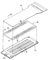
以下、本発明の実施の形態を図面について説明する。図1〜図8は、本発明の第1の実施の形態による圧電式インクジェットプリンタヘッドを示す。これらの図において、金属板製のキャビティプレート10に対して接合されるプレート型の圧電アクチュエータ20の上面には、外部機器との接続のために、フレキシブルフラットケーブル40が接着剤にて重ね接合されているものであり、最下層のキャビティプレート10の下面側に開口されたノズルから下向きにインクが吐出するものとする。
【0012】
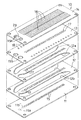
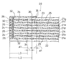
前記キャビティプレート10は、図3及び図4に示すように構成されている。すなわち、ノズルプレート11、二枚のマニホールドプレート12、スペーサプレート13及びベースプレート14の五枚の薄い金属板を積層した構造である。前記ノズルプレート11には、微小径のインク噴出用のノズル15が、当該ノズルプレート11における第1の方向(長辺方向)に沿って2列の千鳥配列状に設けられている。即ち、ノズルプレート11の前記第1の方向と平行な2つの基準線11a、11bに沿って、微小ピッチPの間隔で千鳥状配列にて多数個のノズル15が穿設されている。前記二枚のマニホールドプレート12には、インク通路(請求項の共通インク室に相当)12a、12bが、前記ノズル15の列の両側に沿って延びるように穿設されている。但し、ノズルプレート11に対面する下側マニホールドプレート12におけるインク通路12bは、当該マニホールドプレート12の上側にのみ開放するように凹み形成されている(図4参照)。このインク通路12a、12bは、上側のマニホールドプレート12に対する前記スペーサプレート13の積層により密閉される構造になっている。また、前記ベースプレート14には、その長辺(前記第1の方向)に沿う中心線に対して直交する第2の方向(短辺方向)に延びる細幅の圧力室16の多数個が穿設されている。そして、前記中心線を挟んで左右両側にて平行状の長手基準線14a、14bを設定すると、前記中心線より左側の圧力室16の先端16aは前記左側の長手基準線14a上に位置し、逆に前記長手中心線より右側の圧力室16の先端16aは前記右側の長手基準線14b上に位置し、且つこの左右の圧力室16の先端16aが交互に配置されているので、左右両側の圧力室16は一つおきに互いに逆方向に延びるように交互に配置されていることになる。
【0013】
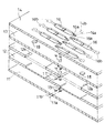
この各圧力室16の先端16aは、前記ノズルプレート11における前記千鳥状配列のノズル15に、前記スペーサプレート13及び両マニホールドプレート12に同じく千鳥状配列にて穿設されている微小径の貫通孔17を介して連通している。一方、前記各圧力室16の他端16bは、前記スペーサプレート13における左右両側部位に穿設された貫通孔18を介して、前記両マニホールドプレート12におけるインク通路12a、12bに連通している。なお、前記他端16bは、図4に示すように、ベースプレート14の下面側にのみ開口するように凹み形成されているものである。また、最上層のベースプレート14の一端部に穿設された供給孔19aの上面には、その上方のインクタンクから供給されるインク中の塵除去のためのフィルタ29が張設されている。
【0014】
これにより、前記ベースプレート14及びスペーサプレート13の一端部に穿設の供給孔19a,19bから前記インク通路12a、12b内に流入したインクは、このインク通路12aから前記各貫通孔18を通って前記各圧力室16内に分配されたのち、この各圧力室16内から前記貫通孔17を通って、当該圧力室16に対応するノズル15に至るという構成になっている。
【0015】
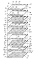
一方、前記圧電アクチュエータ20は、図5及び図6に示すように、9枚の圧電シート21a,21b,21c,21d,21e,21f,21g,22,23を積層した構造で、前記各圧電シートのうち最下段の圧電シート22とそれから上方へ数えて奇数番目の圧電シート21b,21d,21fの上面(広幅面)には、前記キャビティプレート10における各圧力室16の箇所ごとに細幅の個別電極24が、第1の方向(長辺方向)に沿って列状に形成され、各個別電極24は前記第1の方向と直交する第2の方向に沿って各圧電シートの長辺の端縁部近傍まで延びている。下から偶数段目の圧電シート21a,21c,21e,21gの上面(広幅面)には、複数個の圧力室16に対して共通のコモン電極25が形成されている。
【0016】
実施形態においては、前記各個別電極24の幅寸法は対応する圧力室16における平面視での広幅部より少し狭く設定されている。
【0017】
他方、圧力室16は前記のベースプレート14の短辺の中央部側で、前記第1の方向(長辺)に沿って2列状に配列されているので、前記コモン電極25は、その2列の圧力室16、16を一体的に覆うように、偶数段目の圧電シート21a,21c,21e,21gの短辺方向の中央において長辺に沿って延びる平面視略矩形状に形成されると共に、該偶数段目の圧電シート21a,21c,21e,21gの対の短辺の端縁部近傍では当該端縁部のほぼ全長にわたって延びる引き出し部25a,25aが一体的に形成されている。
【0018】
そして、前記偶数段目の圧電シート21a,21c,21e,21gの対の長辺の端縁部近傍の表面であって、前記コモン電極25が形成されていない箇所には、前記各個別電極24と同じ上下位置(対応する位置)に、当該個別電極24と略同じ幅寸法で長さの短いダミー個別電極26を形成する。この場合、図5及び図6に示すように、各ダミー個別電極26の端部は前記コモン電極25の第1の方向(長辺に沿う方向)の側縁に対して適宜の隙間寸法(A1)の切れ目35があるように隔てる。しかも、ダミー個別電極26の層の1つおきの長さをL2とL3(<L2)のように長短に設定して、ダミー個別電極26の端部とコモン電極25の側縁とのパターンの切れ目35の位置を圧電シートの積層の1枚おきに当該圧電シートの第2の方向(短辺方向)にずらせても良い。
【0019】
実施形態では、下から2番目の層(圧電シート21a)及び6番目の層(圧電シート21e)でのダミー個別電極26の長さL2を、4番目の層(圧電シート21c)及び8番目の層(圧電シート21g)でのダミー個別電極26の長さL3より隙間寸法A1だけ長くなるように設定する。
【0020】
このように構成することにより、圧電アクチュエータ20全体としての第2の方向(幅方向)でのダミー個別電極26の端部とコモン電極25の側縁とのパターンの切れ目35の幅が2×A1と大きくなると共に、当該切れ目35箇所における圧電アクチュエータ20全体としての厚さ方向の電極層の密度の第2の方向での偏りが少なくなるから、後工程で焼成した後の圧電アクチュエータ20の幅方向(第2の方向)の反り(前記切れ目35の箇所で上向き凸となる反り)変形量も小さく、その反りも急な角度で折れ曲がったものではなく、大きな半径で穏やかに湾曲したものにできる。その結果、後述するように、接着剤層としての接着剤シート41により圧電アクチュエータ20をキャビティプレート10に接着固定した場合にも、その接着面での隙間(空間)が発生せず、インクジェットとしての製品となった状態でのインク漏れという不良を防止できるという効果を奏する。また、前記接着工程において、圧電アクチュエータ20とキャビティプレート10との広幅面(接着面)が平坦になるように、両者を押しつける接着圧力も低荷重にできるという効果を奏する。
【0021】
他方、最下段の圧電シート22とそれから上方へ数えて奇数番目の圧電シート21b,21d,21fの上面(広幅面)のうち、前記引き出し部25a,25aに対応する位置(同じ上下位置、圧電シートの対の短辺の端縁部近傍)には、ダミーコモン電極27を形成するのである。
【0022】
前記最上段のトップシート23の上面には、その長辺の端縁部に沿って、前記各個別電極24の各々に対する表面電極30と、前記コモン電極25に対する表面電極31とが、設けられている。
【0023】
さらに、前記最下段の圧電シート22を除いて、他の全ての圧電シート21a,21b,21c,21d,21e,21f,21gとトップシート23とには、前記各表面電極30と、それに対応する位置(同じ上下位置)の個別電極24並びにダミー個別電極26とが互いに連通するように、スルーホール32を穿設する。同様に、前記少なくとも1つの表面電極31(実施形態では、トップシート23の4隅の位置の表面電極31)と、それに対応する位置(同じ上下位置)のコモン電極25乃至はその引き出し部25aが互いに連通するように、スルーホール33を穿設し、スルーホール32、33内に充填された導電性材料を介して、各層の個別電極24同士及びそれと対応する位置の表面電極30とが電気的に接続されているように構成し、同じく、各層のコモン電極25同士及びそれと対応する位置の表面電極31とが電気的に接続されているように構成するものである。
【0024】
前記した構成の圧電アクチュエータ20は、以下に述べるような方法で製造される。即ち、前記一つの圧電アクチュエータ20における圧電シート21b,21d,21f、22の複数個をマトリックス状に並べて一体化してなる第1素材シート(セラミックグリーンシート)の表面のうち各圧電シートの箇所に、複数個の個別電極24と、捨てパターンの電極としてのダミーコモン電極27を設ける位置に対応して予めスルーホール32を穿設する。同様に、圧電シート21a,21c,21e,21gの複数個をマトリックス状に並べて一体化してなる第2素材シート(セラミックグリーンシート)の表面のうち各圧電シートの箇所に、複数個のコモン電極25と、捨てパターンの電極としてのダミー個別電極26を設ける位置に対応して予めスルーホール33を穿設する。さらに、前記と同様に、トップシート23の複数個をマトリックス状に並べて一体化してなる第3素材シート(セラミックグリーンシート)の表面のうちトップシート23の箇所に、複数個の表面電極30、31を設ける位置に対してスルーホール32、33を穿設する。
【0025】
そして、各圧電シート21b,21d,21f、22の表面に個別電極24及びダミーコモン電極27を、圧電シート21a,21c,21e,21gの表面にコモン電極25及びダミー個別電極26を、トップシート23の表面に表面電極30、31の箇所を、それぞれ、導電ペーストのスクリーン印刷にて形成すると、前記各スルーホール32、33は、第1、第2素材シートの上下広幅面に貫通しているので、各スルーホール32、33内にも前記導電ペーストが浸入し、該各スルーホール32、33を介して各電極部分でシートの上下面で導電通可能となる。次いで、各グリーンシートを乾燥した後、積層し、次いで積層方向にプレスすることで一体化して、一枚の積層体に形成し、その後焼成する。
【0026】
これにより、上下に積層された複数枚の圧電シート21とトップシートとは上下同じ位置の前記個別電極24及びダミー個別電極26が表面電極30の箇所と電気的に接続されるし、同じく上下複数枚のコモン電極25及びダミーコモン電極27が表面電極31の箇所と電気的に接続されることになる(図6参照)。
【0027】
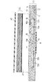
そして、このような構成のプレート型の圧電アクチュエータ20における下面(圧力室16と対面する広幅面)全体に、接着剤層としてのインク非浸透性の合成樹脂材からなる接着剤シート41を予め貼着し、次いで、前記キャビティプレート10に対して、当該圧電アクチュエータ20における各個別電極24が前記キャビティプレート10における各圧力室16の各々に対応するように接着・固定される(図7、図8参照)。また、この圧電アクチュエータ20における上側の表面には、前記フレキシブルフラットケーブル40が重ね押圧されることにより、このフレキシブルフラットケーブル40における各種の配線パターン(図示せず)が、前記各表面電極30、31に電気的に接合される。
【0028】
なお、前記接着剤シート41等の接着剤層の材料としては、少なくともインク非浸透性であり、且つ電気絶縁性を備えたものであって、ナイロン系やダイマー酸ベースのポリアミド樹脂を主成分とするポリアミド系ホットメルト形接着剤、ポリエステル系ホットメルト形接着剤のフィルム状のものを使用しても良いが、ポリオレフィン系ホットメルト形接着剤を前記圧電アクチュエータ20の前記広幅面に塗布してから、キャビティプレート10に接着・固定するようにしても良い。接着層の厚さは約1μm程度である。
【0029】
この構成において、前記圧電アクチュエータ20における各個別電極24のうち任意の個別電極24と、コモン電極25との間に電圧を印加することにより、圧電シート21のうち前記電圧を印加した個別電極24の部分に圧電による積層方向の歪みが発生し、この歪みにて前記各個別電極24に対応する圧力室16の内容積が縮小されることにより、この圧力室16内のインクが、ノズル15から液滴状に噴出して、所定の印字が行われる(図8参照)。
【0030】
上述のように、圧電アクチュエータ20とキャビティプレート10との間に、全ての圧力室16を覆うように、前記接着剤層を介在させることにより、この接着剤層がインクを浸透させない被膜の役割を果たすと共に、圧電アクチュエータ20とキャビティプレート10とを強固に固定する作用も同時にできる。そして、接着剤であるので、その層の厚さを従来のダイヤフラムプレートに比して極めて薄く形成でき、且つ低コストにてインクジェットプリンタヘッドを製造することができるという効果を奏する。また、複数の圧力室16にわたって延びる圧電シート21、22を積層して圧電アクチュエータ20を構成しているから、圧電アクチュエータ20全体の剛性が高くなり、従来のダイヤフラムプレートのような振動を起こすことがなく、高い周波数での駆動を可能にすることができる。そして、圧電アクチュエータ20の広幅面の全体に接着剤層を形成しているから、駆動時の圧電アクチュエータ20と接着剤層とが一体的に伸縮し、高い周波数での駆動時のインク吐出性能が悪化するというおそれもないのである。
【0031】
なお、前記ホットメルト形接着剤を使用すれば、固化までの作業時間を大幅に短縮できるという効果も奏する。
【0032】
なお、実施形態では、圧電シート1枚の厚さが30μmであり、個別電極24、コモン電極25及び表面電極30、31の形成(電極層の厚さは略5μm)時における導電材料の塗布にて当該導電材料は各スルーホール32,33内に浸入(充填)し得る。圧電シートの1枚の厚さが厚い場合には、前記電極(導電)材料の塗布後に塗布面の裏側からの空気の吸引にてスルーホール内への導電材料の浸入(充填)を確実にすることができる。
【0033】
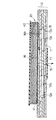
図9〜図11に示す実施形態は、前記スルーホールにかえて、圧電アクチュエータ20の積層体の側面(表面電極30,31が形成される広幅面と直交する側面)に、側面電極35、36を形成し、表面電極30は前記側面電極35を介して前記個別電極24同士、ダミー個別電極26同士を電気的接続させる一方、表面電極31は別の箇所の側面電極36を介して前記コモン電極25同士、ダミーコモン電極27同士を電気的接続させるよう構成したものであり、前記側面電極35、36の厚さ方向の端縁部がキャビティプレート10の表面に直接接触しないように、前記接着剤シート41を圧電アクチュエータ20の下面に延在させるようにして接着してから、キャビティプレート10の表面に接着・固定するようにしても良い。このようにすれば、キャビティプレート10が金属材料等の電気導体であっても、インク非浸透性且つ電気絶縁性材料からなる接着剤シート41にて側面電極35、36の厚さ方向の端縁部が遮られることになり、電気的に短絡しない構成が至極簡単に達成できるという効果を奏する。
【0034】
本発明は、コモン電極25を有する最下層の圧電シートがキャビティシート10におけるベースシート14と対面するように、個別電極24の層とコモン電極25との層との積層順序を変えたものにも適用できることはいうまでもない。
【0035】
【発明の作用・効果】
以上に説明したように、請求項1に記載の発明の圧電式インクジェットプリンタヘッドは、複数個のノズル及びこの各ノズル毎の圧力室を第1の方向に列状に備えたキャビティプレートと、駆動電極への電圧の印加により前記各圧力室ごとに圧電シートを駆動させる圧電アクチュエータとからなり、この圧電アクチェータを、前記キャビティプレートに、当該圧電アクチェータにおける各駆動電極が各圧力室に対応するように接合してなる圧電式インクジェットプリンタヘッドにおいて、前記キャビティプレートは、前記ノズルを形成したノズルプレートと、前記圧力室を両面に開口して形成したベースプレートと、前記ノズルプレートと前記ベースプレートとの間に位置し前記圧力室に供給するインクを収容する共通インク室を有するマニホールドプレートと、前記ベースプレートと前記マニホールドプレートとの間に位置し前記圧力室の両端を前記共通インク室及び前記ノズルにそれぞれ接続する貫通孔を形成したスペーサプレートとが積層され、前記圧力室を前記圧電アクチュエータ側に開口するとともにその圧力室を前記圧電アクチュエータとは反対側の一端において貫通孔を介して前記ノズルと接続するように構成され、前記圧電アクチュエータは、前記複数の圧力室を共通に覆う大きさの圧電シートを積層し、その圧電シート間に前記駆動電極としての、前記圧力室毎に対応する個別電極と、複数の前記圧力室に共通のコモン電極とを介挿して構成され、前記ベースプレートの前記スペーサプレートと反対側であって前記圧力室を開口した側の面と、前記圧電アクチュエータの前記圧力室と対面する側の面との間に介挿されて前記キャビティプレートと前記圧電アクチュエータとを接着固定する、インク非浸透性材料で構成された接着剤層を、前記全ての圧力室を覆うように、前記圧電アクチュエータの圧力室側の面に沿って延在させたものであるから、この接着剤層がインクを浸透させない被膜の役割を果たすと共に、圧電アクチュエータとキャビティプレートとを強固に固定することができる。そして、接着剤であるので、その層の厚さを従来のダイヤフラムプレートに比して極めて薄く形成でき、且つ低コストにてインクジェットプリンタヘッドを製造することができるという効果を奏する。また、圧電アクチュエータの広幅面の全体に接着剤層を形成しているから、駆動時の圧電アクチュエータと接着剤層とが一体的に伸縮し、高い周波数での駆動時のインク吐出性能が悪化するというおそれもないのである。
また、前記接着剤層は、インク非浸透性材料で構成されているものであるから、この接着剤層が圧力室を確実に覆うことができ圧電シート中に前記圧力室中のインクが浸透せず、駆動電極が絶縁破壊されることがなく長期の使用に耐えることができる被膜の役割を果たすと共に、圧電アクチュエータとキャビティプレートとを強固に固定する作用も同時にできるという効果を奏する。
【0036】
加えて、請求項1に記載の発明によると、従来のキャビティプレートと圧電素子との間に設けられていたダイヤフラムプレートに比して、接着剤層はその厚さを極めて薄く形成でき、且つ低コストにてインクジェットプリンタヘッドを製造することができるという効果を奏する。また、複数の圧力室にわたって延びる圧電シートを積層して圧電アクチュエータを構成しているから、圧電アクチュエータ全体の剛性が高くなり、従来のダイヤフラムプレートのような振動を起こすことがなく、高い周波数での駆動を可能にすることができる。そして、圧電アクチュエータの広幅面の全体に接着剤層を形成しているから、駆動時の圧電アクチュエータと接着剤層とが一体的に伸縮し、高い周波数での駆動時のインク吐出性能が悪化するというおそれもない。
【0037】
また、請求項3に記載の発明は、請求項1または請求項2に記載の圧電式インクジェットプリンタヘッドにおいて、前記圧電アクチュエータの側面にその厚さ方向に側面電極を形成し、前記接着剤層は、前記側面電極の厚さ方向の端縁部とキャビティプレートの表面との間に介挿されるように延設した場合には、キャビティプレートが導電性材料であっても、接着剤層によって側面電極の端縁部とキャビティプレートとの接触を遮断することができ、簡単な構成により、電気絶縁性を確保できるという効果を奏する。
【0038】
請求項4に記載の発明の圧電式インクジェットプリンタヘッドの製造方法は、複数個のノズル及びこの各ノズル毎の圧力室を第1の方向に列状に備えたキャビティプレートと、駆動電極への電圧の印加により前記各圧力室ごとに圧電シートを駆動させる圧電アクチュエータとからなり、この圧電アクチェータを、前記キャビティプレートに、当該圧電アクチェータにおける各駆動電極が各圧力室に対応するように接合してなる圧電式インクジェットプリンタヘッドにおいて、前記キャビティプレートは、前記ノズルを形成したノズルプレートと、前記圧力室を両面に開口して形成したベースプレートと、前記ノズルプレートと前記ベースプレートとの間に位置し前記圧力室に供給するインクを収容する共通インク室を有するマニホールドプレートと、前記ベースプレートと前記マニホールドプレートとの間に位置し前記圧力室の両端を前記共通インク室及び前記ノズルにそれぞれ接続する貫通孔を形成したスペーサプレートとを積層して形成し、前記圧力室は、前記キャビティプレートに、前記圧電アクチュエータ側に開口して形成するとともに前記圧電アクチュエータとは反対側の一端において貫通孔を介して前記ノズルと接続して形成し、前記圧電アクチュエータの圧電シートは、前記複数の圧力室を共通に覆う大きさに形成し、前記圧電アクチュエータは、前記圧電シートをその圧電シート間に前記駆動電極としての、前記圧力室毎に対応する個別電極と、複数の前記圧力室に共通のコモン電極とを介挿して積層して形成し、前記圧電アクチュエータの前記圧力室と対面する側の面に予めインク非浸透性材料で構成された接着剤層を形成し、該接着剤層を介して前記圧電アクチュエータの前記面と前記キャビティプレートの前記圧力室を開口した側の面とを接着固定したことを特徴とするものである。
【0039】
従って、極めて簡単でコストを低減した方法により、圧電アクチュエータとキャビティプレートとを固定することができると共に、圧電アクチュエータの広幅面の全体に接着剤層を形成しているから、駆動時の圧電アクチュエータと接着剤層とが一体的に伸縮し、高い周波数での駆動時のインク吐出性能が悪化しないという効果も奏することができるのである。また、前記接着剤層は、インク非浸透性材料で構成されているものであるから、この接着剤層が圧力室を確実に覆うことができ圧電シート中に前記圧力室中のインクが浸透せず、駆動電極が絶縁破壊されることがなく長期の使用に耐えることができる被膜の役割を果たすと共に、圧電アクチュエータとキャビティプレートとを強固に固定する作用も同時にできるという効果を奏する。
【図面の簡単な説明】
【図1】 本発明の実施の形態による圧電式インクジェットプリンタヘッドを示す分解斜視図である。
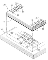
【図2】 キャビティプレートと圧電アクチュエータとの一端部を示す拡大斜視図である。
【図3】 キャビティプレートの分解斜視図である。
【図4】 キャビティプレートの部分的拡大斜視図である。
【図5】 圧電アクチュエータの分解斜視図である。
【図6】 スルーホール部で切断した圧電アクチュエータの部分拡大側断面図である。
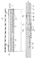
【図7】 図1のVII −VII 線矢視拡大断面図である。
【図8】 フレキシブルフラットケーブルとキャビティプレートと圧電アクチュエータとを接着・固定した状態の拡大断面図である。
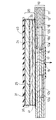
【図9】 第2実施形態におけるキャビティプレートと圧電アクチュエータとの一端部を示す拡大斜視図である。
【図10】 図9におけるX−X線矢視拡大断面図である。
【図11】 接着剤・固定状態の拡大断面図である。
【符号の説明】
10 キャビティプレート
11 ノズルプレート
12 マニホールドプレート
13 スペーサプレート
14 ベースプレート
15 ノズル
16 圧力室
20 圧電アクチュエータ
21a,21b,21c,21d,21e,21f,21g,22 圧電シート
23 トップシート
24 個別電極
25 コモン電極
26 ダミー個別電極
27 ダミーコモン電極
30,31 表面電極
32,33 スルーホール
35、36 側面電極
40 フレキシブルフラットケーブル
41 接着剤層としての接着剤シート[0001]
BACKGROUND OF THE INVENTION
The present invention relates to a configuration of a piezoelectric ink jet printer head and a manufacturing method thereof.
[0002]
[Prior art]
In the prior art on-demand type piezoelectric ink jet printer head, as described in JP-A-62-111758, a plurality of nozzles and a pressure plate for each nozzle are provided on the back surface of a cavity plate. An ink jet printer head is disclosed in which a diaphragm plate is bonded via an adhesive, and a driving piezoelectric element or the like is fixed to one side of the diaphragm plate in correspondence with the pressure chamber portion.
[0003]
This diaphragm plate is a thin metal plate having a thickness of 25 μm or less because it must efficiently transmit the deformation of the piezoelectric element to the pressure chamber.
[0004]
However, in this configuration, there is a problem that it is difficult to bond the piezoelectric element on the diaphragm plate in order to vibrate the diaphragm plate and the piezoelectric ceramic member that is the piezoelectric element integrally. Further, since the diaphragm plate has a very small rigidity of 25 μm or less, when the pressure in the pressure chamber changes due to the deformation of the piezoelectric element, the diaphragm plate itself causes vibration different from that of the piezoelectric element. In order to avoid the influence of this vibration, the driving cycle of the piezoelectric element must be lengthened. That is, there is a problem that the discharge operation at a high frequency cannot be performed. In order to solve these problems, Japanese Patent Application Laid-Open No. 4-341851 filed earlier by the applicant of the present application discloses a cavity plate having a plurality of nozzles and pressure chambers for each nozzle, and each pressure chamber. A plate-type piezoelectric actuator in which a piezoelectric sheet (a green sheet made of a ceramic material) is sandwiched between a formed planar individual electrode and a common electrode common to a plurality of adjacent pressure chambers. In the present invention, the cavity plate is laminated so that each individual electrode in the piezoelectric actuator corresponds to each pressure chamber.
[0005]
[Problems to be solved by the invention]
However Na However, in the latter configuration, the piezoelectric sheet is covered so as to face the pressure chamber, the surface of the cavity plate that is not the pressure chamber is bonded to the piezoelectric sheet, and the piezoelectric sheet made of a ceramic material absorbs moisture. Since it is easy to absorb, there is a problem that dielectric breakdown occurs between the individual electrode and the common electrode due to the ink introduced into the pressure chamber during long-term use. In order to solve this problem, it was considered that a synthetic resin sheet was interposed between the piezoelectric element and the cavity plate as the diaphragm plate. However, the synthetic resin diaphragm plate is different from the metal plate. Further, since the rigidity is low, there is a problem that driving at a high frequency becomes more difficult.
[0006]
It is a technical object of the present invention to provide an ink jet printer head that solves such problems.
[0007]
[Means for Solving the Problems]
In order to achieve this technical problem, a piezoelectric ink jet printer head according to a first aspect of the present invention includes a cavity plate having a plurality of nozzles and pressure chambers for each nozzle arranged in a row in a first direction. Drive electrode A piezoelectric actuator that drives a piezoelectric sheet for each of the pressure chambers by applying a voltage to the piezoelectric actuator. The piezoelectric actuator is joined to the cavity plate so that each drive electrode of the piezoelectric actuator corresponds to each pressure chamber. In the piezoelectric inkjet printer head, the cavity plate is A nozzle plate formed with the nozzle, a base plate formed by opening the pressure chamber on both sides, and a common ink chamber located between the nozzle plate and the base plate and containing ink to be supplied to the pressure chamber. A manifold plate and a spacer plate that is positioned between the base plate and the manifold plate and that has through holes that connect both ends of the pressure chamber to the common ink chamber and the nozzle are laminated, Open the pressure chamber to the piezoelectric actuator side. Speak And the pressure chamber is connected to the nozzle through a through hole at one end opposite to the piezoelectric actuator. Configured to The piezoelectric actuator is A piezoelectric sheet having a size that covers the plurality of pressure chambers in common is stacked, and an individual electrode corresponding to each of the pressure chambers as the drive electrode between the piezoelectric sheets, and a common electrode common to the plurality of pressure chambers Between the base plate and the spacer plate. An ink non-permeable material that is interposed between a surface on the side where the pressure chamber is opened and a surface on the side facing the pressure chamber of the piezoelectric actuator to bond and fix the cavity plate and the piezoelectric actuator. The adhesive layer constituted by the above is extended along the pressure chamber side surface of the piezoelectric actuator so as to cover all the pressure chambers.
[0008]
According to a second aspect of the present invention, there is provided a piezoelectric ink jet printer head according to the first aspect. Before The piezoelectric actuator, except for the piezoelectric sheet adjacent to the base plate among the plurality of piezoelectric sheets, the drive electrode through a conductive material filled in a through hole formed in the thickness direction of the piezoelectric sheet, The surface of the piezoelectric actuator opposite to the base plate Electrode Is connected to.
[0009]
Claims 3 The invention described in claim 1 Or claim 2 In the piezoelectric ink-jet printer head according to claim 1, a side electrode is formed in a thickness direction on a side surface of the piezoelectric actuator, and the adhesive layer includes an edge portion in the thickness direction of the side electrode and a surface of the cavity plate. It is extended so that it may be inserted between.
[0010]
Claim 4 The method of manufacturing a piezoelectric ink jet printer head according to the invention includes a cavity plate having a plurality of nozzles and pressure chambers for each nozzle arranged in a row in a first direction, and applying a voltage to a drive electrode. A piezoelectric ink jet comprising a piezoelectric actuator that drives a piezoelectric sheet for each pressure chamber, and this piezoelectric actuator is joined to the cavity plate so that each drive electrode in the piezoelectric actuator corresponds to each pressure chamber. In the printer head, The cavity plate contains a nozzle plate in which the nozzle is formed, a base plate formed by opening the pressure chamber on both sides, and ink that is positioned between the nozzle plate and the base plate and is supplied to the pressure chamber. A manifold plate having a common ink chamber and a spacer plate positioned between the base plate and the manifold plate and having through holes respectively connecting both ends of the pressure chamber to the common ink chamber and the nozzle are laminated. Forming, The pressure chamber is formed in the cavity plate so as to open to the piezoelectric actuator side, and connected to the nozzle through a through hole at one end opposite to the piezoelectric actuator. The sheet is formed in a size that covers the plurality of pressure chambers in common, The piezoelectric actuator is formed by laminating the piezoelectric sheets between the piezoelectric sheets with the individual electrodes corresponding to each of the pressure chambers as the drive electrodes and a common electrode common to the plurality of pressure chambers. And An adhesive layer made of an ink non-permeable material is formed in advance on the surface of the piezoelectric actuator that faces the pressure chamber, and the surface of the piezoelectric actuator and the cavity plate are interposed through the adhesive layer. The pressure chamber is opened and bonded to the surface on the side where the pressure chamber is opened.
[0011]
DETAILED DESCRIPTION OF THE INVENTION
Hereinafter, embodiments of the present invention will be described with reference to the drawings. 1 to 8 show a piezoelectric inkjet printer head according to a first embodiment of the present invention. In these drawings, a flexible
[0012]
The
[0013]
The
[0014]
As a result, the ink that has flowed into the
[0015]
On the other hand, the
[0016]
In the embodiment, the width of each
[0017]
On the other hand, since the
[0018]
The
[0019]
In the embodiment, the length L2 of the dummy
[0020]
With this configuration, the width of the pattern cut 35 between the end of the dummy
[0021]
On the other hand, on the upper surface (wide surface) of the lowermost
[0022]
On the upper surface of the uppermost
[0023]
Further, except for the lowermost
[0024]
The
[0025]
The
[0026]
As a result, the plurality of piezoelectric sheets 21 and the top sheet that are stacked one above the other are electrically connected to the location of the
[0027]
Then, an
[0028]
The material of the adhesive layer such as the
[0029]
In this configuration, by applying a voltage between any
[0030]
As described above, by interposing the adhesive layer so as to cover all the
[0031]
In addition, if the said hot-melt-type adhesive agent is used, there also exists an effect that the working time until solidification can be shortened significantly.
[0032]
In the embodiment, the thickness of one piezoelectric sheet is 30 μm, and the conductive material is applied when the
[0033]
In the embodiment shown in FIGS. 9 to 11, the
[0034]
The present invention is also applicable to the one in which the layer order of the
[0035]
[Operation and effect of the invention]
As described above, the piezoelectric ink jet printer head according to the first aspect of the present invention includes a cavity plate having a plurality of nozzles and pressure chambers for each nozzle arranged in a row in the first direction, and a drive. electrode A piezoelectric actuator that drives a piezoelectric sheet for each of the pressure chambers by applying a voltage to the piezoelectric actuator. The piezoelectric actuator is joined to the cavity plate so that each drive electrode of the piezoelectric actuator corresponds to each pressure chamber. In the piezoelectric inkjet printer head, the cavity plate is A nozzle plate formed with the nozzle, a base plate formed by opening the pressure chamber on both sides, and a common ink chamber located between the nozzle plate and the base plate and containing ink to be supplied to the pressure chamber. A manifold plate and a spacer plate that is positioned between the base plate and the manifold plate and that has through holes that connect both ends of the pressure chamber to the common ink chamber and the nozzle are laminated, Open the pressure chamber to the piezoelectric actuator side. Speak The pressure chamber is connected to the nozzle through a through hole at one end opposite to the piezoelectric actuator. Configured to The piezoelectric actuator is A piezoelectric sheet having a size that covers the plurality of pressure chambers in common is stacked, and an individual electrode corresponding to each of the pressure chambers as the drive electrode between the piezoelectric sheets, and a common electrode common to the plurality of pressure chambers Between the base plate and the spacer plate, An ink non-permeable material that is interposed between a surface on the side where the pressure chamber is opened and a surface on the side facing the pressure chamber of the piezoelectric actuator to bond and fix the cavity plate and the piezoelectric actuator. Since the adhesive layer constituted by is extended along the pressure chamber side surface of the piezoelectric actuator so as to cover all the pressure chambers, the adhesive layer does not allow ink to permeate. The piezoelectric actuator and the cavity plate can be firmly fixed. And since it is an adhesive agent, the thickness of the layer can be formed extremely thin compared with the conventional diaphragm plate, and there exists an effect that an inkjet printer head can be manufactured at low cost. Further, since the adhesive layer is formed on the entire wide surface of the piezoelectric actuator, the piezoelectric actuator and the adhesive layer are integrally expanded and contracted during driving, and the ink ejection performance during driving at a high frequency is deteriorated. There is no fear of that.
Further, since the adhesive layer is made of an ink impermeable material, the adhesive layer can reliably cover the pressure chamber, and the ink in the pressure chamber can penetrate into the piezoelectric sheet. In addition, the driving electrode plays a role of a coating that can withstand long-term use without being broken down, and at the same time, the piezoelectric actuator and the cavity plate can be firmly fixed.
[0036]
In addition, according to the invention described in claim 1, Compared to the diaphragm plate provided between the conventional cavity plate and the piezoelectric element, the adhesive layer can be formed extremely thin, and an inkjet printer head can be manufactured at low cost. There is an effect. In addition, since the piezoelectric actuator is configured by laminating piezoelectric sheets extending over multiple pressure chambers, the overall rigidity of the piezoelectric actuator is increased, and vibrations such as those of a conventional diaphragm plate are not caused. Can be driven. Since the adhesive layer is formed on the entire wide surface of the piezoelectric actuator, the piezoelectric actuator and the adhesive layer are integrally expanded and contracted during driving, and the ink ejection performance during driving at a high frequency is deteriorated. There is no fear.
[0037]
Claims 3 The invention described in claim 1 Or claim 2 In the piezoelectric ink-jet printer head according to claim 1, a side electrode is formed in a thickness direction on a side surface of the piezoelectric actuator, and the adhesive layer includes an edge portion in the thickness direction of the side electrode and a surface of the cavity plate. If the cavity plate is made of a conductive material, the adhesive layer can block the contact between the edge of the side electrode and the cavity plate even if the cavity plate is made of a conductive material. With such a configuration, there is an effect that electrical insulation can be secured.
[0038]
Claim 4 The method of manufacturing a piezoelectric ink jet printer head according to the invention includes a cavity plate having a plurality of nozzles and pressure chambers for each nozzle arranged in a row in a first direction, and applying a voltage to a drive electrode. A piezoelectric ink jet comprising a piezoelectric actuator that drives a piezoelectric sheet for each pressure chamber, and this piezoelectric actuator is joined to the cavity plate so that each drive electrode in the piezoelectric actuator corresponds to each pressure chamber. In the printer head, The cavity plate contains a nozzle plate in which the nozzle is formed, a base plate formed by opening the pressure chamber on both sides, and ink that is positioned between the nozzle plate and the base plate and is supplied to the pressure chamber. A manifold plate having a common ink chamber and a spacer plate positioned between the base plate and the manifold plate and having through holes respectively connecting both ends of the pressure chamber to the common ink chamber and the nozzle are laminated. Forming, The pressure chamber is formed in the cavity plate so as to open to the piezoelectric actuator side, and connected to the nozzle through a through hole at one end opposite to the piezoelectric actuator. The sheet is formed in a size that covers the plurality of pressure chambers in common, The piezoelectric actuator is formed by laminating the piezoelectric sheets between the piezoelectric sheets with the individual electrodes corresponding to each of the pressure chambers as the drive electrodes and a common electrode common to the plurality of pressure chambers. And An adhesive layer made of an ink non-permeable material is formed in advance on the surface of the piezoelectric actuator that faces the pressure chamber, and the surface of the piezoelectric actuator and the cavity plate are interposed through the adhesive layer. The pressure chamber is opened and bonded to the surface on the side where the pressure chamber is opened.
[0039]
Therefore, the piezoelectric actuator and the cavity plate can be fixed by an extremely simple and cost-saving method, and the adhesive layer is formed on the entire wide surface of the piezoelectric actuator. The adhesive layer expands and contracts integrally, and there is an effect that the ink discharge performance at the time of driving at a high frequency does not deteriorate. Further, since the adhesive layer is made of an ink impermeable material, the adhesive layer can reliably cover the pressure chamber, and the ink in the pressure chamber can penetrate into the piezoelectric sheet. In addition, the driving electrode plays a role of a coating that can withstand long-term use without being broken down, and at the same time, the piezoelectric actuator and the cavity plate can be firmly fixed.
[Brief description of the drawings]
FIG. 1 is an exploded perspective view showing a piezoelectric inkjet printer head according to an embodiment of the present invention.
FIG. 2 is an enlarged perspective view showing one end portions of a cavity plate and a piezoelectric actuator.
FIG. 3 is an exploded perspective view of a cavity plate.
FIG. 4 is a partially enlarged perspective view of a cavity plate.
FIG. 5 is an exploded perspective view of a piezoelectric actuator.
FIG. 6 is a partially enlarged side cross-sectional view of a piezoelectric actuator cut at a through-hole portion.
7 is an enlarged cross-sectional view taken along the line VII-VII in FIG.
FIG. 8 is an enlarged cross-sectional view of a state in which a flexible flat cable, a cavity plate, and a piezoelectric actuator are bonded and fixed.
FIG. 9 is an enlarged perspective view showing one end of a cavity plate and a piezoelectric actuator in a second embodiment.
10 is an enlarged sectional view taken along line XX in FIG.
FIG. 11 is an enlarged cross-sectional view of an adhesive and a fixed state.
[Explanation of symbols]
10 Cavity plate
11 Nozzle plate
12 Manifold plate
13 Spacer plate
14 Base plate
15 nozzles
16 Pressure chamber
20 Piezoelectric actuator
21a, 21b, 21c, 21d, 21e, 21f, 21g, 22 Piezoelectric sheet
23 Top sheet
24 Individual electrodes
25 Common electrode
26 Dummy individual electrode
27 Dummy common electrode
30, 31 Surface electrode
32, 33 Through hole
35, 36 Side electrode
40 Flexible flat cable
41 Adhesive sheet as an adhesive layer
Claims (4)
前記キャビティプレートは、前記ノズルを形成したノズルプレートと、前記圧力室を両面に開口して形成したベースプレートと、前記ノズルプレートと前記ベースプレートとの間に位置し前記圧力室に供給するインクを収容する共通インク室を有するマニホールドプレートと、前記ベースプレートと前記マニホールドプレートとの間に位置し前記圧力室の両端を前記共通インク室及び前記ノズルにそれぞれ接続する貫通孔を形成したスペーサプレートとが積層され、前記圧力室を前記圧電アクチュエータ側に開口するとともにその圧力室を前記圧電アクチュエータとは反対側の一端において貫通孔を介して前記ノズルと接続するように構成され、
前記圧電アクチュエータは、前記複数の圧力室を共通に覆う大きさの圧電シートを積層し、その圧電シート間に前記駆動電極としての、前記圧力室毎に対応する個別電極と、複数の前記圧力室に共通のコモン電極とを介挿して構成され、
前記ベースプレートの前記スペーサプレートと反対側であって前記圧力室を開口した側の面と、前記圧電アクチュエータの前記圧力室と対面する側の面との間に介挿されて前記キャビティプレートと前記圧電アクチュエータとを接着固定する、インク非浸透性材料で構成された接着剤層を、前記全ての圧力室を覆うように、前記圧電アクチュエータの圧力室側の面に沿って延在させたことを特徴とする圧電式インクジェットプリンタヘッド。A plurality of nozzles and cavity plates each having a pressure chamber for each nozzle arranged in a row in the first direction, and a piezoelectric actuator for driving the piezoelectric sheet for each pressure chamber by applying a voltage to the drive electrode In the piezoelectric inkjet printer head in which this piezoelectric actuator is joined to the cavity plate so that each drive electrode in the piezoelectric actuator corresponds to each pressure chamber,
The cavity plate contains a nozzle plate in which the nozzle is formed, a base plate formed by opening the pressure chamber on both sides, and ink that is positioned between the nozzle plate and the base plate and is supplied to the pressure chamber. A manifold plate having a common ink chamber, and a spacer plate that is positioned between the base plate and the manifold plate and that has through holes that connect both ends of the pressure chamber to the common ink chamber and the nozzle, are laminated. wherein the said piezoelectric actuator to open port to Rutotomoni the pressure chambers the pressure chamber on the piezoelectric actuator side is configured to connect to the nozzle through the through-hole at one end of the opposite side,
The piezoelectric actuator is formed by laminating piezoelectric sheets having a size that covers the plurality of pressure chambers in common, the individual electrodes corresponding to the pressure chambers as the drive electrodes between the piezoelectric sheets, and the plurality of pressure chambers. Is configured with a common electrode common to
The cavity plate and the piezoelectric element are interposed between a surface of the base plate opposite to the spacer plate and opening the pressure chamber, and a surface of the piezoelectric actuator facing the pressure chamber. An adhesive layer composed of a non-ink-permeable material that adheres and fixes to the actuator extends along the pressure chamber side surface of the piezoelectric actuator so as to cover all the pressure chambers. A piezoelectric inkjet printer head.
前記キャビティプレートは、前記ノズルを形成したノズルプレートと、前記圧力室を両面に開口して形成したベースプレートと、前記ノズルプレートと前記ベースプレートとの間に位置し前記圧力室に供給するインクを収容する共通インク室を有するマニホールドプレートと、前記ベースプレートと前記マニホールドプレートとの間に位置し前記圧力室の両端を前記共通インク室及び前記ノズルにそれぞれ接続する貫通孔を形成したスペーサプレートとを積層して形成し、
前記圧力室は、前記キャビティプレートに、前記圧電アクチュエータ側に開口して形成するとともに前記圧電アクチュエータとは反対側の一端において貫通孔を介して前記ノズルと接続して形成し、
前記圧電アクチュエータの圧電シートは、前記複数の圧力室を共通に覆う大きさに形成し、
前記圧電アクチュエータは、前記圧電シートをその圧電シート間に前記駆動電極として の、前記圧力室毎に対応する個別電極と、複数の前記圧力室に共通のコモン電極とを介挿して積層して形成し、
前記圧電アクチュエータの前記圧力室と対面する側の面に予めインク非浸透性材料で構成された接着剤層を形成し、該接着剤層を介して前記圧電アクチュエータの前記面と前記キャビティプレートの前記圧力室を開口した側の面とを接着固定したことを特徴とする圧電式インクジェットプリンタヘッドの製造方法。A plurality of nozzles and cavity plates each having a pressure chamber for each nozzle arranged in a row in the first direction, and a piezoelectric actuator for driving the piezoelectric sheet for each pressure chamber by applying a voltage to the drive electrode In the piezoelectric inkjet printer head in which this piezoelectric actuator is joined to the cavity plate so that each drive electrode in the piezoelectric actuator corresponds to each pressure chamber,
The cavity plate contains a nozzle plate in which the nozzle is formed, a base plate formed by opening the pressure chamber on both sides, and ink that is positioned between the nozzle plate and the base plate and is supplied to the pressure chamber. A manifold plate having a common ink chamber and a spacer plate positioned between the base plate and the manifold plate and having through holes respectively connecting both ends of the pressure chamber to the common ink chamber and the nozzle are laminated. Forming,
The pressure chamber is formed in the cavity plate so as to open to the piezoelectric actuator side and connected to the nozzle through a through hole at one end opposite to the piezoelectric actuator,
The piezoelectric sheet of the piezoelectric actuator is formed in a size that covers the plurality of pressure chambers in common,
The piezoelectric actuator is formed by laminating the piezoelectric sheets between the piezoelectric sheets with the individual electrodes corresponding to each of the pressure chambers as the drive electrodes and a common electrode common to the plurality of pressure chambers. And
An adhesive layer made of an ink non-permeable material is formed in advance on the surface of the piezoelectric actuator that faces the pressure chamber, and the surface of the piezoelectric actuator and the cavity plate are interposed through the adhesive layer. A method of manufacturing a piezoelectric ink jet printer head, wherein a pressure chamber is opened and bonded to a surface on the side where the pressure chamber is opened.
Priority Applications (2)
| Application Number | Priority Date | Filing Date | Title |
|---|---|---|---|
| JP2000251426A JP3772654B2 (en) | 2000-08-22 | 2000-08-22 | Piezoelectric ink jet printer head and manufacturing method thereof |
| US09/933,155 US6648455B2 (en) | 2000-08-22 | 2001-08-21 | Piezoelectric ink-jet printer head and method of fabricating same |
Applications Claiming Priority (1)
| Application Number | Priority Date | Filing Date | Title |
|---|---|---|---|
| JP2000251426A JP3772654B2 (en) | 2000-08-22 | 2000-08-22 | Piezoelectric ink jet printer head and manufacturing method thereof |
Publications (2)
| Publication Number | Publication Date |
|---|---|
| JP2002059547A JP2002059547A (en) | 2002-02-26 |
| JP3772654B2 true JP3772654B2 (en) | 2006-05-10 |
Family
ID=18740835
Family Applications (1)
| Application Number | Title | Priority Date | Filing Date |
|---|---|---|---|
| JP2000251426A Expired - Fee Related JP3772654B2 (en) | 2000-08-22 | 2000-08-22 | Piezoelectric ink jet printer head and manufacturing method thereof |
Country Status (2)
| Country | Link |
|---|---|
| US (1) | US6648455B2 (en) |
| JP (1) | JP3772654B2 (en) |
Families Citing this family (27)
| Publication number | Priority date | Publication date | Assignee | Title |
|---|---|---|---|---|
| US6729717B2 (en) * | 2000-08-30 | 2004-05-04 | Brother Kogyo Kabushiki Kaisha | Ink-jet head and method of fabricating same |
| US6595628B2 (en) * | 2001-02-19 | 2003-07-22 | Brother Kogyo Kabushiki Kaisha | Laminated piezoelectric element for use as a drive device |
| US6846069B2 (en) * | 2002-05-10 | 2005-01-25 | Brother Kogyo Kabushiki Kaisha | Ink-jet head |
| US6994428B2 (en) | 2002-05-21 | 2006-02-07 | Brother Kogyo Kabushiki Kaisha | Ink-jet printing head having a plurality of actuator units and/or a plurality of manifold chambers |
| JP4135448B2 (en) | 2002-09-17 | 2008-08-20 | ブラザー工業株式会社 | Method for manufacturing droplet ejecting apparatus |
| JP3876986B2 (en) * | 2002-09-24 | 2007-02-07 | ブラザー工業株式会社 | Inkjet head |
| JP4145760B2 (en) | 2002-10-03 | 2008-09-03 | セイコーエプソン株式会社 | Piezoelectric actuator unit and manufacturing method thereof |
| JP4324757B2 (en) | 2002-10-04 | 2009-09-02 | ブラザー工業株式会社 | Inkjet printer head |
| JP2004136461A (en) | 2002-10-15 | 2004-05-13 | Brother Ind Ltd | Liquid pressure generation mechanism |
| US7073894B2 (en) | 2003-02-13 | 2006-07-11 | Brother Kogyo Kabushiki Kaisha | Ink jet printer head |
| US7690770B2 (en) | 2003-07-08 | 2010-04-06 | Brother Kogyo Kabushiki Kaisha | Sheet-member stacked structure, lead frame, lead-frame stacked structure, sheet-member stacked and adhered structure, and ink jet printer head |
| JP2005254579A (en) * | 2004-03-10 | 2005-09-22 | Brother Ind Ltd | Droplet ejector |
| US7479729B2 (en) | 2004-05-19 | 2009-01-20 | Brother Kogyo Kabushiki Kaisha | Piezoelectric actuator, ink-jet head provided with the same, ink-jet printer, and method for manufacturing piezoelectric actuator |
| JP4632026B2 (en) * | 2004-11-17 | 2011-02-16 | ブラザー工業株式会社 | Droplet discharge device |
| JP2006341508A (en) * | 2005-06-09 | 2006-12-21 | Brother Ind Ltd | Inkjet head |
| JP2006341509A (en) * | 2005-06-09 | 2006-12-21 | Brother Ind Ltd | Inkjet head |
| US20070120896A1 (en) * | 2005-11-30 | 2007-05-31 | Xerox Corporation | Drop generator |
| US8113635B2 (en) | 2007-01-16 | 2012-02-14 | Brother Kogyo Kabushiki Kaisha | Liquid discharge apparatus and check method of the same |
| US8104860B2 (en) * | 2007-09-28 | 2012-01-31 | Brother Kogyo Kabushiki Kaisha | Ink-jet recording apparatus including abnormality judging portion |
| JP2009094120A (en) * | 2007-10-04 | 2009-04-30 | Brother Ind Ltd | Piezoelectric actuator, droplet discharge head using the same, and method of manufacturing piezoelectric actuator |
| JP4961373B2 (en) * | 2008-03-12 | 2012-06-27 | 株式会社リコー | Liquid ejection head and image forming apparatus |
| US8348393B2 (en) * | 2008-03-17 | 2013-01-08 | Hewlett-Packard Development Company, L.P. | Print head diaphragm support |
| JP4582173B2 (en) | 2008-03-28 | 2010-11-17 | ブラザー工業株式会社 | Liquid transfer device |
| JP4784677B2 (en) | 2009-03-31 | 2011-10-05 | ブラザー工業株式会社 | Method for manufacturing liquid discharge head |
| WO2014003772A1 (en) * | 2012-06-29 | 2014-01-03 | Hewlett-Packard Development Company, L.P. | Fabricating a fluid ejection device |
| JP5995718B2 (en) * | 2012-12-28 | 2016-09-21 | エスアイアイ・プリンテック株式会社 | Head chip, head chip manufacturing method, liquid ejecting head, and liquid ejecting apparatus |
| CN107206789B (en) * | 2015-04-30 | 2019-11-15 | 惠普发展公司,有限责任合伙企业 | fluid ejection device |
Family Cites Families (6)
| Publication number | Priority date | Publication date | Assignee | Title |
|---|---|---|---|---|
| US4680595A (en) | 1985-11-06 | 1987-07-14 | Pitney Bowes Inc. | Impulse ink jet print head and method of making same |
| JP3128857B2 (en) | 1991-05-20 | 2001-01-29 | ブラザー工業株式会社 | Piezoelectric inkjet printer head |
| JP3105608B2 (en) * | 1991-12-05 | 2000-11-06 | 株式会社リコー | Inkjet head |
| JPH10264380A (en) * | 1997-03-25 | 1998-10-06 | Fujitsu Ltd | Ink jet print head, driving method and manufacturing method thereof |
| JPH11227200A (en) * | 1998-02-18 | 1999-08-24 | Fujitsu Ltd | Head for forming fine ink droplets and method of manufacturing the same |
| JP2001010048A (en) * | 1999-07-01 | 2001-01-16 | Fujitsu Ltd | Ink jet head, method of manufacturing the same, and recording apparatus |
-
2000
- 2000-08-22 JP JP2000251426A patent/JP3772654B2/en not_active Expired - Fee Related
-
2001
- 2001-08-21 US US09/933,155 patent/US6648455B2/en not_active Expired - Lifetime
Also Published As
| Publication number | Publication date |
|---|---|
| JP2002059547A (en) | 2002-02-26 |
| US6648455B2 (en) | 2003-11-18 |
| US20020024567A1 (en) | 2002-02-28 |
Similar Documents
| Publication | Publication Date | Title |
|---|---|---|
| JP3772654B2 (en) | Piezoelectric ink jet printer head and manufacturing method thereof | |
| JP3804459B2 (en) | Multilayer piezoelectric element | |
| JP3809787B2 (en) | Inkjet printer head | |
| JP3951119B2 (en) | Inkjet printer head | |
| JP4243850B2 (en) | Multilayer piezoelectric element and ink jet recording head including the same | |
| JP3705085B2 (en) | Piezoelectric inkjet printer head | |
| JP3692900B2 (en) | Piezoelectric ink jet printer head and manufacturing method thereof | |
| US6536880B2 (en) | Piezoelectric ink jet printer head and method for manufacturing same | |
| JP2004241669A (en) | Manufacturing method of piezoelectric actuator | |
| JP3705090B2 (en) | Piezoelectric inkjet printer head | |
| JP3767395B2 (en) | Manufacturing method of multilayer piezoelectric element | |
| JP2005254721A (en) | Inkjet recording head | |
| JP3849780B2 (en) | Apparatus provided with piezoelectric actuator and inkjet printer head | |
| JP3719169B2 (en) | Inkjet printer head | |
| JP2003011356A (en) | Inkjet printer head | |
| JP4603762B2 (en) | Inkjet head manufacturing method | |
| JP3747787B2 (en) | Inkjet printer head manufacturing method | |
| JP3815228B2 (en) | Piezoelectric inkjet printer head | |
| JP2004114558A (en) | Ink jet printer head and method of manufacturing the same | |
| JP4035722B2 (en) | Inkjet printer head and manufacturing method thereof | |
| JP3991695B2 (en) | Inkjet head | |
| JP3876909B2 (en) | Piezoelectric inkjet printer head | |
| JP2003341050A (en) | Ink jet printer head and method of manufacturing the same | |
| JP2004148591A (en) | Droplet ejector | |
| JP2002127408A (en) | Piezoelectric actuator |
Legal Events
| Date | Code | Title | Description |
|---|---|---|---|
| A977 | Report on retrieval |
Free format text: JAPANESE INTERMEDIATE CODE: A971007 Effective date: 20041029 |
|
| A131 | Notification of reasons for refusal |
Free format text: JAPANESE INTERMEDIATE CODE: A131 Effective date: 20050104 |
|
| A521 | Written amendment |
Free format text: JAPANESE INTERMEDIATE CODE: A523 Effective date: 20050304 |
|
| A02 | Decision of refusal |
Free format text: JAPANESE INTERMEDIATE CODE: A02 Effective date: 20051011 |
|
| A521 | Written amendment |
Free format text: JAPANESE INTERMEDIATE CODE: A523 Effective date: 20051209 |
|
| A911 | Transfer to examiner for re-examination before appeal (zenchi) |
Free format text: JAPANESE INTERMEDIATE CODE: A911 Effective date: 20051222 |
|
| TRDD | Decision of grant or rejection written | ||
| A01 | Written decision to grant a patent or to grant a registration (utility model) |
Free format text: JAPANESE INTERMEDIATE CODE: A01 Effective date: 20060124 |
|
| A61 | First payment of annual fees (during grant procedure) |
Free format text: JAPANESE INTERMEDIATE CODE: A61 Effective date: 20060206 |
|
| R150 | Certificate of patent or registration of utility model |
Ref document number: 3772654 Country of ref document: JP Free format text: JAPANESE INTERMEDIATE CODE: R150 Free format text: JAPANESE INTERMEDIATE CODE: R150 |
|
| FPAY | Renewal fee payment (event date is renewal date of database) |
Free format text: PAYMENT UNTIL: 20090224 Year of fee payment: 3 |
|
| FPAY | Renewal fee payment (event date is renewal date of database) |
Free format text: PAYMENT UNTIL: 20100224 Year of fee payment: 4 |
|
| FPAY | Renewal fee payment (event date is renewal date of database) |
Free format text: PAYMENT UNTIL: 20100224 Year of fee payment: 4 |
|
| FPAY | Renewal fee payment (event date is renewal date of database) |
Free format text: PAYMENT UNTIL: 20110224 Year of fee payment: 5 |
|
| FPAY | Renewal fee payment (event date is renewal date of database) |
Free format text: PAYMENT UNTIL: 20120224 Year of fee payment: 6 |
|
| FPAY | Renewal fee payment (event date is renewal date of database) |
Free format text: PAYMENT UNTIL: 20120224 Year of fee payment: 6 |
|
| FPAY | Renewal fee payment (event date is renewal date of database) |
Free format text: PAYMENT UNTIL: 20130224 Year of fee payment: 7 |
|
| FPAY | Renewal fee payment (event date is renewal date of database) |
Free format text: PAYMENT UNTIL: 20140224 Year of fee payment: 8 |
|
| LAPS | Cancellation because of no payment of annual fees |