JP3772636B2 - Airbag - Google Patents
Airbag Download PDFInfo
- Publication number
- JP3772636B2 JP3772636B2 JP2000094708A JP2000094708A JP3772636B2 JP 3772636 B2 JP3772636 B2 JP 3772636B2 JP 2000094708 A JP2000094708 A JP 2000094708A JP 2000094708 A JP2000094708 A JP 2000094708A JP 3772636 B2 JP3772636 B2 JP 3772636B2
- Authority
- JP
- Japan
- Prior art keywords
- airbag
- curved
- inflating
- portions
- bulging
- Prior art date
- Legal status (The legal status is an assumption and is not a legal conclusion. Google has not performed a legal analysis and makes no representation as to the accuracy of the status listed.)
- Expired - Lifetime
Links
- 230000008878 coupling Effects 0.000 claims description 66
- 238000010168 coupling process Methods 0.000 claims description 66
- 238000005859 coupling reaction Methods 0.000 claims description 66
- 230000002093 peripheral effect Effects 0.000 claims description 65
- 238000009941 weaving Methods 0.000 description 9
- 235000021189 garnishes Nutrition 0.000 description 8
- 238000005192 partition Methods 0.000 description 5
- 230000008961 swelling Effects 0.000 description 5
- 239000011247 coating layer Substances 0.000 description 4
- 239000002184 metal Substances 0.000 description 4
- 230000000694 effects Effects 0.000 description 2
- 229920003002 synthetic resin Polymers 0.000 description 2
- 239000000057 synthetic resin Substances 0.000 description 2
- 239000004952 Polyamide Substances 0.000 description 1
- 239000000853 adhesive Substances 0.000 description 1
- 230000001070 adhesive effect Effects 0.000 description 1
- 238000005452 bending Methods 0.000 description 1
- 239000013256 coordination polymer Substances 0.000 description 1
- 238000009434 installation Methods 0.000 description 1
- 230000000149 penetrating effect Effects 0.000 description 1
- 229920002647 polyamide Polymers 0.000 description 1
- 229920000728 polyester Polymers 0.000 description 1
- 238000009958 sewing Methods 0.000 description 1
- 229910052710 silicon Inorganic materials 0.000 description 1
- 239000010703 silicon Substances 0.000 description 1
- 238000000638 solvent extraction Methods 0.000 description 1
- 238000003466 welding Methods 0.000 description 1
Images


Landscapes
- Air Bags (AREA)
Description
【0001】
【発明の属する技術分野】
本発明は、自動車のルーフサイドレール部やシート等に搭載される頭部保護エアバッグ装置や側突用エアバッグ装置等に使用されるエアバッグに関する。
【0002】
【従来の技術とその課題】
従来、例えば、頭部保護エアバッグ装置用のエアバッグでは、車内側のドアや窓部の開口周縁に折り畳まれて収納されており、膨張用ガスの流入時、開口を覆うように、展開膨張されていた。このエアバッグは、膨張用ガスを流入させて車内側壁部と車外側壁部とを離すように膨らむ膨張部を備えて構成されていた。
【0003】
そして、膨張部の領域内には、膨張部を構成する周壁の対向する部位相互を線状に結合させてなる線状結合部が、複数、配設されていた(特開平11−321535号公報等参照)。このような線状結合部は、膨張部の周縁や中央部位での厚さを略均等にするために、配設され、さらに、頭部保護エアバッグ装置にあっては、前後方向に張力を発揮させて、車外側への押圧力を受けても、エアバッグが、車外側に移動しないようにするために、配設されていた。
【0004】
しかし、線状結合部の端末部位の面積が小さいと、膨張部の膨張時、線状結合部の端末部位に応力集中が生じ易くなって、端末部位近傍の膨張部を構成する周壁が破損してしまう場合があった。。
【0005】
このため、線状結合部は、端末部位を含めて、幅広の寸法で配設することとなっていた。
【0006】
しかしながら、このように線状結合部を、端末部位を含めて幅広寸法で形成しては、膨張部の膨張用ガスを流入させる容積や膨張エリアを減少させる事態を招き、エアバッグのクッション性に影響を与えてしまう。
【0007】
本発明は、上述の課題を解決するものであり、展開膨張時の周壁の破損を招くことなく、かつ、容積や膨張エリアの減少を極力抑えて、線状結合部を配設させることができるエアバッグを提供することを目的とする。
【0008】
【課題を解決するための手段】
本発明に係るエアバッグは、膨張用ガスを流入させて膨らむ膨張部の領域内に、前記膨張部を構成する周壁の対向する部位相互を線状に結合させてなる線状結合部が、配設されているエアバッグであって、
前記線状結合部が、
略直線状の基部と、該基部と接続されて、端末側に向かって曲線状に曲がる曲線部と、該曲線部の先端に配置されて、前記曲線部の外周縁となだらかに外周縁を接続させる膨出部と、を備えて構成されるとともに、
前記基部における前記曲線部と接続する部位付近の幅寸法をB0、前記曲線部の外周縁の曲率半径をR1、前記膨出部の外周縁の曲率半径をR2とした時、B0/2<R2<R1として、配設されていることを特徴とする。
【0009】
そして、前記曲線部近傍の前記基部の部位は、流入する前記膨張用ガスの主流の流れと略平行に配設し、
前記膨出部は、前記膨張用ガスの主流の流れと略直交する方向に、前記基部からずれて配設させることが望ましい。
【0010】
また、前記膨出部は、前記膨張用ガスの主流の流れる主流路から分岐する分岐流路側に、前記基部からずれて配設させても良い。
【0011】
さらに、エアバッグを袋織りによって形成する場合には、前記曲線部の外周縁の曲率半径R1を、15〜100mmとし、前記膨出部の外周縁の曲率半径R2を、10〜15mmとすることが望ましい。
【0012】
【発明の効果】
本発明に係るエアバッグでは、線状結合部の端末部位が、略直線状の基部から、曲線状の曲線部を経て、膨出部に連なるように、形成されている。そして、膨出部は、曲線部の外周縁となだらかに外周縁を接続させて、かつ、その膨出部外周縁の曲率半径R2を、基部の幅寸法B0の二分の一倍以上と大きくしているため、膨張部の膨張時に、その膨出部の周囲に応力集中が生じ難い。
【0013】
また、曲線部外周縁の曲率半径R1も、膨出部外周縁の曲率半径R2より大きくしていることから、その曲線部の周囲にも、応力集中が生じ難い。
【0014】
そして、線状結合部の端末部位では、膨出部が幅広となっているものの、基部と膨出部とを結ぶ曲線部の内周縁側を、凹ませるようにして、曲線部や基部を細くすることが可能となって、膨張部の容積を減少させることを、極力抑えることができる。
【0015】
したがって、本発明に係るエアバッグでは、展開膨張時に周壁の破損を招くことなく、かつ、容積や膨張エリアの減少を極力抑えて、線状結合部を配設させることができる。
【0016】
そして、請求項2に記載したように、基部における曲線部近傍の部位を、流入する膨張用ガスの主流の流れと略平行に配設し、膨出部を、膨張用ガスの主流の流れと略直交する方向に、基部からずらして配設させれば、膨出部が、膨張用ガスの主流と直接的に干渉せず、一層、膨出部の周囲に応力集中を生じ難くすることができる。その結果、端末部位の膨出部の面積を含めて、線状結合部の面積を小さくさせることが可能となって、エアバッグの容積や膨張エリアを、一層、増大させることが可能となる。
【0017】
また、請求項3に記載したように、膨出部を、膨張用ガスの主流の流れる主流路から分岐する分岐流路側に、基部からずらして配設させれば、一層、膨張部が、膨張用ガスの主流と干渉し難くなって、膨出部の周囲に応力集中を生じ難くすることができ、これまた、端末部位の膨出部の面積を含めて、線状結合部の面積を小さくさせることが可能となって、エアバッグの容積や膨張エリアの増大を可能にする。
【0018】
さらに、請求項4に記載したように、エアバッグを袋織りで織成する場合、線状結合部の端末部位における曲線部外周縁の曲率半径R1を、15〜100mmとして、膨出部外周縁の曲率半径R2を、10〜15mmとしておけば、容積や膨張エリアの減少を極力抑えて、線状結合部を配設させることができる。
【0019】
ちなみに、曲線部外周縁の曲率半径R1が、15mm未満では、膨張部の膨張時、曲線部の周囲に応力集中が生じ易くなって、エアバッグの展開膨張時に周壁を破損させる虞れが生じ、100mmを越えれば、基部からの曲り状態が小さくなって、膨出部に膨張用ガスの主流が干渉し易くなり、これを防ぐように曲線部を長くすれば、エアバッグの容積や膨張エリアを狭めてしまうことから、好ましくない。
【0020】
また、膨出部外周縁の曲率半径R2が、10mm未満では、膨張部の膨張時、膨出部の周囲に応力集中が生じ易くなって、エアバッグの展開膨張時に周壁を破損させる虞れが生じ、15mmを越えれば、周囲に応力集中が生じ難いものの、エアバッグの容積や膨張エリアを狭めてしまうことから、好ましくない。
【0021】
【発明の実施の形態】
以下、本発明の一実施形態を図面に基づいて説明する。
【0022】
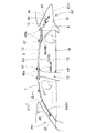
実施形態のエアバッグ10は、図1・2に示す頭部保護エアバッグ装置Mに使用されるものであり、車内側のドアや窓部の開口Wの上縁側周縁におけるフロントピラー部FP、ルーフサイドレール部RR、及び、リヤピラー部RPにわたって、折り畳まれて収納されている。
【0023】
頭部保護エアバッグ装置Mは、エアバッグ10、インフレーター42、取付ブラケット43・46・48・49、及び、エアバッグカバー5、を備えて構成されている。
【0024】
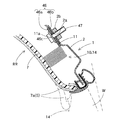
インフレーター42は、図1に示すように、折り畳まれたエアバッグ10に膨張用ガスを供給するシリンダタイプとしており、エアバッグ10の後述するガス流入部12が外装されることとなる。
【0025】
取付ブラケット43は、板金製として、エアバッグ10のガス流入部12を外装させたインフレーター42を、ガス流入部12ごと外周側から挟持し、2本の取付ボルト44を利用して、リヤピラー部RPの車内側におけるボディ1側の板金製のインナパネル2に取り付けることとなる。
【0026】
取付ブラケット46は、図1・2に示すように、板金製として、エアバッグ10における後述する前部側の2つの取付部11を挟持するもので、それぞれ、車内側Iの内プレート46aと車外側Oの外プレート46bとを備えて構成され、内・外プレート46a・46bには、各取付部11の取付孔11aに対応する取付孔46cが貫通されている。そして、図2に示すように、取付ボルト47を、取付孔46c・11aに挿通させて、インナパネル2の取付孔2a周縁に固着されたナット2bに螺合させることにより、各取付部11がインナパネル2に取り付けられることとなる。
【0027】
取付ブラケット48・49は、図1に示すように、板金製として、エアバッグ10における他の部位の2つずつの取付部11を挟持するもので、それぞれ、取付ブラケット46の内プレート46aと同様な車内側Iに配置される2つずつの内プレート48a・49aを備えるとともに、取付ブラケット46の外プレート46bが二つ分一体化された車外側の一つの外プレート48b・49bを備えて構成されている。各外プレート48b・49bは、折り畳まれたエアバッグ10の車外側と下面側とを支持して、エアバッグ10の展開膨張時にリヤピラー部RPのガーニッシュ8やセンターピラー部CPのガーニッシュ9における車外側に侵入しないように、断面を略L字状としている。また、各内プレート48a・49aと外プレート48b・49bとには、取付部11の取付孔11aに対応する位置に、取付孔(図示せず)が貫通されている。
【0028】
エアバッグカバー5は、フロントピラー部FPに配置されるピラーガーニッシュ6とルーフサイドレール部RRに配置されるルーフヘッドライニング7とのそれぞれの下縁側に配置されるリッド6a・7aから構成されている。
【0029】
フロントピラーガーニッシュ6は、合成樹脂製として、フロントピラー部FPの車内側におけるボディ1のインナパネル2に取付固定され、下縁側に、エアバッグ10の展開膨張時、エアバッグ10を突出可能に、車内側Iに開くリッド6aを備えている。
【0030】
ルーフヘッドライニング7は、図1・2に示すように、合成樹脂製として、ルーフサイドレール部RRの車内側Iにおけるボディ1のインナパネル2に取付固定され、下縁側に、展開膨張時のエアバッグ10を突出可能に、車内側に開くリッド7aを備えている。
【0031】
エアバッグ10は、図1〜4に示すように、インフレーター42からの膨張用ガスを流入させて、折り畳み状態から展開して、開口Wを覆うエアバッグ本体13と、インフレーター42からの膨張用ガスをエアバッグ本体13に導くガス流入部12と、エアバッグ本体13の上縁10a側に設けられる取付部11と、を備えて構成されている。
【0032】
ガス流入部12は、後述する連通膨張部14Cの上縁側の周縁結合部18と延設結合部19の区画部19aとが後方へ筒形状に延設されるような形態で、形成されている。このガス流入部12は、インフレーター42に外装されることとなる。
【0033】
取付部11は、エアバッグ本体13の上縁10a側の周縁結合部18から上方へ突出するように、複数配置されて、インナパネル2に取り付けるための取付ブラケット46・48・49が固着されることとなる。各取付部11には、取付ボルト47を挿通させる取付孔11aが開口されている。
【0034】
エアバッグ本体13は、ガス流入部12に連通して、膨張用ガスを流入させて膨張する膨張部14と、膨張用ガスを流入させない非膨張部17と、を備えて構成されている。
【0035】
なお、エアバッグ本体13は、取付部11・ガス流入部12とともに、ポリアミド糸やポリエステル糸等を使用して、一体的に袋織りされて形成されている。また、膨張部14の後述する周壁15の車内側壁部15aと車外側壁部15bとは、それぞれ、1インチ平方当たりの糸の打ち込み本数を、経糸49〜58本、緯糸49〜58本(実施形態では、経糸56本、緯糸50.5本)として、平織りにより織成されている。なお、後述する周縁結合部18・延設結合部19・線状結合部20・26・31・36は、1インチ平方当たり、車内側壁部15aの二倍の打ち込み本数となる。また、袋織りして織成した後には、適宜、耐熱性を高めるとともに膨張用ガスの漏れを防止するように、シリコン等を塗布したコーティング層を設けて、エアバッグ10を製造する。ちなみに、コーティング層は、織成後には、内周面側にコーティング剤を塗布できないことから、外周面側に形成する。
【0036】
そして、膨張部14は、車両の前席側の位置に配置可能な前席用膨張部14Fと、後席側の位置に配置可能な後席用膨張部14Bと、ガス流入部12に連通するとともに、前・後席用膨張部14F・14Bの上部相互を連通する連通膨張部14Cと、から構成されている。そして、各膨張部14F・14B・14Cは、それぞれ、車内側壁部15aと車外側壁部15bとを備えた周壁15で囲まれて、構成されている。
【0037】
非膨張部17は、車内側壁部15aと車外側壁部15bとを結合させて構成されており、実施形態の場合、周縁結合部18、延設結合部19、線状結合部20・26・31・36、及び、板状結合部41、から構成されている。周縁結合部18は、膨張部14の周縁を囲むように配設され、延設結合部19は、連通膨張部14Cと後席用膨張部14Bとを区画するように、周縁結合部18の後方側から前方へ延びる区画部19aと、区画部19aから後席用膨張部14Bの領域内に侵入する二本の縦棒部19bと、を備えて構成されている。
【0038】
板状結合部41は、エアバッグ本体13の前部側の三角板状部41aと、前・後席用膨張部14F・14Bとの間における連通膨張部14Cの下方の長方形板状部41bと、から構成されている。板状結合部41は、ガス流入部12からエアバッグ本体13の前部にかけてのエアバッグ本体13の全体形状を確保するとともに、膨張部14の容積を小さくして、膨張完了までの時間を短くするために設定されている。
【0039】
周縁結合部18・延設結合部19・線状結合部20・26・36は、板状結合部41に比べて、密に織成され、板状結合部41は、膨張部14との境界部位でなく、膨張用ガスの漏れ対策を考慮しなくとも良いことから、粗く織成されている。
【0040】
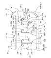
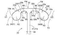
線状結合部20・26・31は、前席用膨張部14Fの領域内で、周縁結合部18から離れて設けられている。さらに、線状結合部20・31は、図5・6・8に示すように、前席用膨張部14Fの前・後部側で、それぞれ、縦棒部21・32と横棒部22・33とを備えたT字形状として構成され、線状結合部26は、線状結合部20・31間で、縦棒部27を備えた略I字形状として構成されている。
【0041】
なお、ガス流入部12に流入される膨張用ガスGは、主流GMが、連通膨張部14C内を前方に流れ、さらに、前席用膨張部14Fの上部を前方側に流れることとなり、そして、主流GMから分岐する分岐流G1・G2・G3・G4・G5が、周縁結合部18・線状結合部20・26・31・延設結合部19のそれぞれの間から、下方に流れて、前席用膨張部14Fと後席用膨張部14Bとを膨張させることとなる。
【0042】
そして、線状結合部20における膨張用ガスGの主流GMに近い側の横棒部22では、図6に示すように、縦棒部21近傍における主流GMの流れと略平行な直線状の基部22aと、基部22aの前後両端部22b・22cから、前後方向の両先端側に向かって曲線状に下方へ曲がる曲線部23F・23Bと、各曲線部23F・23Bの先端に配置されて、曲線部23F・23Bの外周縁23aとなだらかに外周縁24aを接続させる膨出部24F・24Bと、を備えて構成されている。なお、曲線部23Bが基部22aから曲り始める始点22cは、縦棒部21を中心とすると、曲線部23Fが基部22aから曲り始める始点22bに比べて、縦棒部21から離れた位置としている。
【0043】
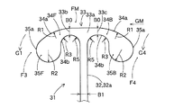
また、線状結合部31における膨張用ガスGの主流GMに近い側の横棒部33では、図8に示すように、縦棒部32近傍における主流GMの流れと略平行な直線状の基部33aと、基部33aの前後両端部33b・33cから、縦棒部32を中心とする略左右対称形として、前後方向の両先端側に向かって曲線状に下方へ曲がる曲線部34F・34Bと、各曲線部34F・34Bの先端に配置されて、曲線部34F・34Bの外周縁34aとなだらかに外周縁35aを接続させる膨出部35F・35Bと、を備えて構成されている。
【0044】
なお、この線状結合部31も、曲線部34Bが基部33aから曲り始める始点33cは、縦棒部32を中心とすると、曲線部34Fが基部33aから曲り始める始点33bに比べて、縦棒部32から僅かに離れた位置としている。
【0045】
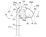
線状結合部26は、図5・7に示すように、縦棒部27と、縦棒部27の上端27cから上後方へ曲りさらに下方側へ曲る曲線部28と、曲線部28の外周縁28aとなだらかに外周縁29aを接続させる膨出部29と、を備えて構成されている。なお、曲線部28の外周縁28aは、曲率半径R1F・R1Bを異ならせた前部側の外周縁28aFと後部側の外周縁28aBとの二つ曲線で構成されている。
【0046】
そして、実施形態の場合、各部の寸法に関しては、各基部22a・33a・27における曲線部23F・23B・28・34F・34Bと接続する部位付近の幅寸法B0を、7mm、曲線部23F・23B・28・34F・34Bの外周縁23a・28aB・34aの曲率半径R1・R1Bを、50mm、曲率半径R1Fを、17mm、膨出部24F・24B・29・35F・35Bの外周縁24a・29a・35aの曲率半径R2を、12.5mmとしている。また、曲線部23F・23B・28・34F・34Bの内周縁23b・28b・34bの曲率半径R3を、10mmとし、さらに、内周縁23b・28b・34b側の縦棒部21・27・32・19b側に連なる曲率半径R5を、10mmとしている。
【0047】
さらに、実施形態の場合には、各線状結合部20・26・31の縦棒部21・27・32は、上部側の一般部21a・27a・32aの幅寸法B1を、7mm、下端の膨出部21b・27b・32bの曲率半径R4を、12.5mmとしている。
【0048】
なお、延設結合部19の区画部19aの前端側にも、図9に示すように、線状結合部36が配設されており、膨張用ガスGの主流GMの流れと略平行な直線状の基部37から、前方先端側に向かって曲線状に下方へ曲がる曲線部38と、曲線部38の先端に配置されて、曲線部38の外周縁38aとなだらかに外周縁39aを接続させる膨出部39と、が配置されている。これらの各部の寸法B0・R1・R2・R5も、他の線状結合部31等と同様である。同様に、延設結合部19の縦棒部19bも、他の線状結合部31等の縦棒部32と寸法を等しくして、下端に膨出部19cを配設させている。なお、曲線部38の内周縁38bの曲率半径R6は、15mmとしている。
【0049】
そして、これらの線状結合部20・26・31・36・縦棒部19bは、膨張部14が膨張用ガスを流入させて膨張した際、前・後席用膨張部14F・14Bの肉厚を略均等にするように区画するとともに、ガス流入部12の先端付近からエアバッグ本体13の前部にかけて、張力を発揮させて、エアバッグ本体13が、車外側への押圧力を受けても、車外側へ移動しないようにするために、設けられている。
【0050】
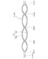
このエアバッグ10の車両への搭載について説明すると、袋織りして織成し、さらに、所定形状に裁断して取付孔11a等を設け、さらに、適宜、コーティング層を設けた後、まず、所定の折り機で折り畳む。この折り畳み状態は、実施形態の場合、図3の二点鎖線に示すように、順次、山折りと谷折りとの折目Cを入れて、エアバッグ下縁10b側をエアバッグ上縁10aに接近させるような蛇腹折りとしている。
【0051】
折り畳んだ後には、折り崩れ防止用の破断可能なテープ(図符号省略)で、エアバッグ10をくるむとともに、インフレーター42・取付ブラケット43・46・48・49を取り付けて、エアバッグ組立体を形成する。なお、取付ブラケット48・49の部位には、エアバッグ10と各取付ブラケット48・49とが分離しないように、破断可能なテープ(図符号省略)をさらに巻いておく。
【0052】
そして、各取付ブラケット43・46・48・49をインナパネル2の所定位置に配置させ、各取付孔11a等を挿通させてボルト44・47止めし、各取付ブラケット43・46・48・49をインナパネル2に固定して、エアバッグ組立体をボディ1に取り付ける。ついで、フロントピラーガーニッシュ6やルーフヘッドライニング7をボディ1に取り付け、さらに、リヤピラーガーニッシュ8やセンターピラーガーニッシュ9をボディ1に取り付ければ、エアバッグ10が頭部保護エアバッグ装置Mとともに車両に搭載されることとなる。
【0053】
エアバッグ装置Mの車両への搭載後、インフレーター42が作動されれば、インフレーター42からの膨張用ガスGが、ガス流入部12から膨張部14の連通膨張部14C内に流れ、さらに、膨張用ガスGの主流GMが、分岐流G1・G2・G3・G4・G5に分岐され、各分岐流G1・G2・G3・G4・G5が前席用膨張部14Fと後席用膨張部14Bとに流れて、エアバッグ10の膨張部14が、折りを解消させつつ、膨張し始める。そして、エアバッグ10は、くるんでおいたテープを破断させ、さらに、フロントピラーガーニッシュ6やルーフヘッドライニング7のリッド6a・7aを押し開いて、図1・2の二点鎖線で示すように、開口Wを覆うように、大きく膨張することとなる。
【0054】
そして、実施形態のエアバッグ10では、線状結合部20・26・31・36における膨張用ガスGの主流GMに接近している側の端末部位が、それぞれ、略直線状の基部22a・27・33a・37から、曲線状の曲線部23F・23B・28・34F・34B・38を経て、膨出部24F・24B・29・35F・35B・39に連なるように、形成されている。そして、各膨出部24F・24B・29・35F・35B・39は、それぞれ、曲線部23F・23B・28・34F・34B・38の外周縁23a・28aF・28aB・34a・38aとなだらかに外周縁24a・29a・35a・39aを接続させている。さらに、各膨出部外周縁24a・29a・35a・39aの曲率半径R2を、それらに連なる各基部22a・27・33a・37の幅寸法B0の二分の一倍以上と大きくしているため、膨張部14F・14Bの膨張時に、各膨出部24F・24B・29・35F・35B・39の周囲に応力集中が生じ難い。
【0055】
また、各曲線部23F・23B・28・34F・34B・38の外周縁23a・28aF・28aB・34a・38aの曲率半径R1も、それらに連なる各膨出部24F・24B・29・35F・35B・39の外周縁24a・29a・35a・39aの曲率半径R2より大きくしていることから、各曲線部23F・23B・28・34F・34B・38の周囲にも、応力集中が生じ難い。
【0056】
そして、線状結合部20・26・31・36における膨張用ガスGの主流GMに接近している側の端末部位では、各膨出部24F・24B・29・35F・35B・39が幅広となっているものの、それぞれ、基部と膨出部とを結ぶ曲線部23F・23B・28・34F・34B・38の内周縁23b・28bF・28bB・34b・38b側を、凹ませるようにして、曲線部23F・23B・28・34F・34B・38や基部22a・27・33a・37、さらに、それらに連なる縦棒部21・32も細くすることが可能となって、膨張部14F・14Bの容積を減少させることを、極力抑えることができる。
【0057】
したがって、実施形態のエアバッグ10では、展開膨張時の周壁15の破損を招くことなく、かつ、容積や膨張エリアの減少を極力抑えて、線状結合部20・26・31・36を配設させることができる。
【0058】
さらに、実施形態のエアバッグ10では、膨張用ガスGの主流GMに直接的に対向するように配置されて、連通膨張部14Cに接近している線状結合部31の横棒部33の部位において、図5・8に示すように、基部33aにおける曲線部34B近傍の部位を、流入する膨張用ガスGの主流GMの流れと略平行に配設し、膨出部35Bを、膨張用ガスGの主流GMの流れと略直交する下方側に、基部33aからずれて配設させている。そのため、膨出部35Bが、膨張用ガス主流GMと直接的に干渉せず、一層、膨出部35Bの周囲に応力集中を生じ難くすることができる。その結果、端末部位の膨出部35Bの面積を含めて、線状結合部31の面積を小さくさせることが可能となって、エアバッグ10の容積や膨張エリアを増大させることができることとなる。
【0059】
さらに、実施形態では、各線状結合部20・26・31・36の各膨出部24F・24B・29・35F・35B・39を、それぞれ、膨張用ガスGの主流GMの流れる主流路FMから分岐して、分岐流G1・G2・G3・G4・G5として流れる分岐流路F1・F2・F3・F4・F5側に、基部22a・27c・33a・37からずれて配設させている。そのため、各膨張部24F・24B・29・35F・35B・39が、一層、膨張用ガスGの主流GMと干渉し難くなって、各膨張部24F・24B・29・35F・35B・39の周囲に応力集中を生じ難くすることができ、これまた、端末部位の膨出部24F・24B・29・35F・35B・39の面積を含めて、線状結合部20・26・31・36の面積を小さくさせることが可能となって、エアバッグ10の容積や膨張エリアを増大させることができる。
【0060】
さらに、実施形態では、エアバッグ10が袋織りで織成されていても、各線状結合部20・26・31・36の端末部位における曲線部23F・23B・28・34F・34B・38の外周縁23a・28aF・28aB・34a・38a側の曲率半径R1・R1F・R1Bを、15〜100mm内の50mmや17mmとして、膨出部24F・24B・29・35F・35B・39の曲率半径R2を、10〜15mm内の12.5mmとしていることから、エアバッグ10の容積や膨張エリアの減少を極力抑えて、線状結合部20・26・31・36を配設させることができる。
【0061】
ちなみに、エアバッグ10を袋織りで形成する場合、曲線部外周縁23a・28a・34a・38aの曲率半径R1・R1F・R1Bが、15mm未満では、膨張部14の膨張時、曲線部の周囲に応力集中が生じ易くなり、100mmを越えれば、基部からの曲り状態が小さくなって、膨出部24F・24B・29・35F・35B・39に膨張用ガスの主流GMが干渉し易くなり、これを防ぐように曲線部を長くすれば、エアバッグ10の容積や膨張エリアを狭めてしまうことから、好ましくない。
【0062】
また、膨出部外周縁24a・29a・35a・39aの曲率半径R2が、10mm未満では、膨張部14の膨張時、膨出部の周囲に応力集中が生じ易くなり、15mmを越えれば、周囲に応力集中が生じ難いものの、エアバッグ10の容積や膨張エリアを狭めてしまうことから、好ましくない。
【0063】
なお、実施形態のエアバッグ10では、袋織りによって製造したものを示したが、縫製、接着剤を使用する接着、高周波ウェルダ等を使用する溶着等を利用して、エアバッグを製造しても良く、その場合に設ける線状結合部に本発明を応用しても良い。
【0064】
また、実施形態では、頭部保護エアバッグ装置Mに使用されるエアバッグ10について説明したが、本発明は、例えば、膨張した際の膨張部の厚さを全域にわたって略均等にしたり、膨張部位を区画したりするため等に、線状結合部が配設されるエアバッグであれば、本発明を適用することができ、頭部保護エアバッグ装置の他、シートに搭載される側突用エアバッグ装置のエアバッグ等に、本発明を応用することができる。
【図面の簡単な説明】
【図1】本発明に係る一実施形態のエアバッグが使用される頭部保護エアバッグ装置の使用態様を示す概略図である。
【図2】図1のII−II部位の概略縦断面図である。
【図3】同実施形態のエアバッグが単体で膨張した状態を示す正面図である。
【図4】図3のIV−IV部位の断面図である。
【図5】同実施形態のエアバッグにおける前席用膨張部の拡大正面図である。
【図6】同実施形態のエアバッグにおける線状結合部の端末部位を示す拡大図である。
【図7】同実施形態のエアバッグにおける他の線状結合部の端末部位を示す拡大図である。
【図8】同実施形態のエアバッグにおけるさらに他の線状結合部の端末部位を示す拡大図である。
【図9】同実施形態のエアバッグにおけるさらに他の線状結合部の端末部位を示す拡大図である。
【符号の説明】
10…エアバッグ、
14…膨張部、
15…周壁、
15a…車内側壁部、
15b…車外側壁部、
20・26・31・36…線状結合部、
22a・27・33a・37…基部、
23・28・34・38…曲線部、
23a・28a・34a・38a…外周、
24・29・35・39…膨出部、
24a・29a・35a・39a…外周縁、
G…膨張用ガス、
GM…主流、
FM…主流路、
F1・F2・F3・F4・F5…分岐流路。[0001]
BACKGROUND OF THE INVENTION
The present invention relates to an airbag used for a head protection airbag device, a side collision airbag device, and the like mounted on a roof side rail portion, a seat, and the like of an automobile.
[0002]
[Prior art and its problems]
Conventionally, for example, in an airbag for a head protection airbag device, the airbag is folded and stored around the opening periphery of a door or window on the inside of the vehicle. It had been. The airbag is configured to include an inflating portion that inflates so that an inflating gas flows in and separates the vehicle inner wall portion and the vehicle outer wall portion.
[0003]
In the region of the inflating portion, a plurality of linear coupling portions formed by linearly coupling the opposing portions of the peripheral walls constituting the inflating portion are arranged (Japanese Patent Laid-Open No. 11-321535). Etc.). Such a linear coupling portion is disposed in order to make the thickness at the periphery and the central portion of the inflating portion substantially uniform, and further, in the head protection airbag device, tension is applied in the front-rear direction. In order to prevent the airbag from moving to the outside of the vehicle even when subjected to a pressing force to the outside of the vehicle, the airbag is disposed.
[0004]
However, if the area of the end portion of the linear coupling portion is small, stress concentration tends to occur at the end portion of the linear coupling portion when the expansion portion is inflated, and the peripheral wall constituting the expansion portion near the end portion is damaged. There was a case. .
[0005]
For this reason, the linear coupling portion has been arranged with a wide dimension including the terminal portion.
[0006]
However, if the linear coupling part is formed in a wide dimension including the terminal part in this way, a situation in which the volume and the inflation area into which the inflation gas flows into the inflation part is reduced is caused, and the cushioning property of the airbag is increased. It will have an effect.
[0007]
The present invention solves the above-mentioned problems, and can dispose the linear coupling portion without causing damage to the peripheral wall during expansion and expansion, and suppressing the decrease in volume and expansion area as much as possible. An object is to provide an airbag.
[0008]
[Means for Solving the Problems]
In the airbag according to the present invention, a linear coupling portion formed by linearly coupling opposing portions of the peripheral walls constituting the inflating portion is arranged in a region of the inflating portion that inflates by inflating the inflation gas. An installed airbag,
The linear coupling portion is
A substantially linear base, a curved portion connected to the base and curved in a curved shape toward the terminal side, and arranged at the tip of the curved portion to connect the outer peripheral edge gently with the outer peripheral edge of the curved portion And a bulging portion to be configured,
B0 / 2 <R2 where B0 is the width dimension of the base portion near the portion connected to the curved portion, R1 is the radius of curvature of the outer peripheral edge of the curved portion, and R2 is the radius of curvature of the outer peripheral edge of the bulged portion. <R1 is provided as a feature.
[0009]
The base portion in the vicinity of the curved portion is disposed substantially in parallel with the main flow of the inflating gas flowing in,
It is desirable that the bulging portion be disposed so as to be displaced from the base portion in a direction substantially perpendicular to the main flow of the inflation gas.
[0010]
In addition, the bulging portion may be disposed on the side of the branch flow path branched from the main flow path through which the main flow of the expansion gas flows and is shifted from the base portion.
[0011]
Further, when the airbag is formed by bag weaving, the curvature radius R1 of the outer peripheral edge of the curved portion is 15 to 100 mm, and the curvature radius R2 of the outer peripheral edge of the bulging portion is 10 to 15 mm. Is desirable.
[0012]
【The invention's effect】
In the airbag according to the present invention, the end portion of the linear coupling portion is formed so as to continue from the substantially linear base portion to the bulging portion via the curved curved portion. Then, the bulging part gently connects the outer peripheral edge to the outer peripheral edge of the curved part, and the curvature radius R2 of the outer peripheral edge of the bulging part is larger than one half of the width dimension B0 of the base part. Therefore, when the expanding portion is expanded, stress concentration is unlikely to occur around the expanded portion.
[0013]
Further, since the radius of curvature R1 of the outer peripheral edge of the curved portion is also larger than the radius of curvature R2 of the outer peripheral edge of the bulging portion, stress concentration hardly occurs around the curved portion.
[0014]
And although the bulging part is wide at the end part of the linear coupling part, the curved part and the base part are narrowed so that the inner peripheral side of the curved part connecting the base part and the bulging part is recessed. It is possible to reduce the volume of the expansion part as much as possible.
[0015]
Therefore, in the airbag according to the present invention, it is possible to dispose the linear coupling portion without causing damage to the peripheral wall during deployment and inflating the volume and the expansion area as much as possible.
[0016]
Further, as described in
[0017]
In addition, as described in claim 3, if the bulging portion is disposed on the branch flow channel side branched from the main flow channel through which the main flow of the expansion gas flows, the expansion portion is further expanded. It becomes difficult to interfere with the main flow of the working gas, and it is possible to make it difficult for stress concentration to occur around the bulging portion, and also to reduce the area of the linear coupling portion including the area of the bulging portion of the terminal portion. It becomes possible to increase the volume of the airbag and the expansion area.
[0018]
Furthermore, as described in claim 4, when the airbag is woven by bag weaving, the radius of curvature R1 of the outer periphery of the curved portion at the end portion of the linear coupling portion is set to 15 to 100 mm, and the outer periphery of the bulging portion If the radius of curvature R2 is set to 10 to 15 mm, it is possible to dispose the linear coupling portion while minimizing the reduction in volume and expansion area.
[0019]
By the way, if the radius of curvature R1 of the outer peripheral edge of the curved portion is less than 15 mm, stress concentration tends to occur around the curved portion when the inflating portion is inflated, and the peripheral wall may be damaged when the airbag is deployed and inflated. If it exceeds 100 mm, the bent state from the base portion becomes small, and the main flow of the inflation gas tends to interfere with the bulging portion. If the curved portion is lengthened to prevent this, the volume of the airbag and the expansion area are reduced. Since it narrows, it is not preferable.
[0020]
In addition, when the radius of curvature R2 of the outer peripheral edge of the bulging portion is less than 10 mm, stress concentration tends to occur around the bulging portion when the inflating portion is inflated, and the peripheral wall may be damaged when the airbag is deployed and inflated. If it exceeds 15 mm, stress concentration is unlikely to occur in the surroundings, but the volume of the airbag and the expansion area are reduced, which is not preferable.
[0021]
DETAILED DESCRIPTION OF THE INVENTION
Hereinafter, an embodiment of the present invention will be described with reference to the drawings.
[0022]
The
[0023]
The head protecting airbag device M includes the
[0024]
As shown in FIG. 1, the
[0025]
The mounting
[0026]
As shown in FIGS. 1 and 2, the mounting
[0027]
As shown in FIG. 1, the mounting
[0028]
The
[0029]
The front pillar garnish 6 is made of synthetic resin and is fixedly attached to the
[0030]
As shown in FIGS. 1 and 2, the roof head lining 7 is made of synthetic resin and is fixedly attached to the
[0031]
1-4, the
[0032]
The
[0033]
A plurality of mounting
[0034]
The airbag
[0035]
The airbag
[0036]
The
[0037]
The
[0038]
The plate-like connecting portion 41 includes a triangular plate-like portion 41a on the front side of the
[0039]
The peripheral coupling portion 18, the extended coupling portion 19, the
[0040]
The
[0041]
The expansion gas G flowing into the
[0042]
Then, in the
[0043]
Further, in the horizontal bar portion 33 on the side close to the main flow GM of the expansion gas G in the
[0044]
The
[0045]
As shown in FIGS. 5 and 7, the
[0046]
In the case of the embodiment, with respect to the dimensions of the respective parts, the width dimension B0 in the vicinity of the portion connected to the
[0047]
Further, in the case of the embodiment, the
[0048]
As shown in FIG. 9, a
[0049]
These linear connecting
[0050]
The installation of the
[0051]
After folding, the
[0052]
Then, the mounting
[0053]
If the
[0054]
In the
[0055]
The curvature radii R1 of the outer
[0056]
And in the terminal site | part of the side close | similar to the main stream GM of the gas G for expansion | swelling in the
[0057]
Therefore, in the
[0058]
Furthermore, in the
[0059]
Further, in the embodiment, the bulging
[0060]
Furthermore, in the embodiment, even if the
[0061]
Incidentally, when the
[0062]
Further, if the radius of curvature R2 of the outer
[0063]
The
[0064]
Moreover, although the
[Brief description of the drawings]
FIG. 1 is a schematic view showing a usage mode of a head protection airbag device in which an airbag according to an embodiment of the present invention is used.
FIG. 2 is a schematic longitudinal sectional view taken along the line II-II in FIG.
FIG. 3 is a front view showing a state where the airbag according to the embodiment is inflated alone;
4 is a cross-sectional view taken along the line IV-IV in FIG. 3;
FIG. 5 is an enlarged front view of a front seat inflating portion in the airbag of the embodiment.
FIG. 6 is an enlarged view showing a terminal portion of the linear coupling portion in the airbag of the embodiment.
FIG. 7 is an enlarged view showing a terminal portion of another linear coupling portion in the airbag of the embodiment.
FIG. 8 is an enlarged view showing a terminal portion of still another linear coupling portion in the airbag of the embodiment.
FIG. 9 is an enlarged view showing a terminal portion of still another linear coupling portion in the airbag of the embodiment.
[Explanation of symbols]
10 ... Airbag,
14 ... inflatable part,
15 ...
15a ... the inner wall of the vehicle,
15b ... car outer wall part,
20, 26, 31, 36 ... linear coupling part,
22a, 27, 33a, 37 ... base,
23.28.34.38 ... curve,
23a, 28a, 34a, 38a ... outer periphery,
24, 29, 35, 39 ... bulge,
24a, 29a, 35a, 39a ... outer periphery,
G ... expansion gas,
GM ... mainstream,
FM ... main flow path,
F1, F2, F3, F4, F5: Branch flow path.
Claims (4)
前記線状結合部が、
略直線状の基部と、該基部と接続されて、端末側に向かって曲線状に曲がる曲線部と、該曲線部の先端に配置されて、前記曲線部の外周縁となだらかに外周縁を接続させる膨出部と、を備えて構成されるとともに、
前記基部における前記曲線部と接続する部位付近の幅寸法をB0、前記曲線部の外周縁の曲率半径をR1、前記膨出部の外周縁の曲率半径をR2とした時、
B0/2<R2<R1として、
配設されていることを特徴とするエアバッグ。The airbag is provided with a linear coupling portion that linearly couples the opposing portions of the peripheral walls constituting the inflating portion in the region of the inflating portion that inflates by inflating the inflating gas. And
The linear coupling portion is
A substantially linear base, a curved portion connected to the base and curved in a curved shape toward the terminal side, and arranged at the tip of the curved portion to connect the outer peripheral edge gently with the outer peripheral edge of the curved portion And a bulging portion to be configured,
When the width dimension in the vicinity of the portion connected to the curved portion in the base portion is B0, the radius of curvature of the outer peripheral edge of the curved portion is R1, and the radius of curvature of the outer peripheral edge of the bulging portion is R2.
As B0 / 2 <R2 <R1 ,
An airbag characterized by being disposed.
前記膨出部が、前記膨張用ガスの主流の流れと略直交する方向に、前記基部からずれて配設されていることを特徴とする請求項1に記載のエアバッグ。The base portion in the vicinity of the curved portion is disposed substantially in parallel with the main flow of the inflating gas flowing in,
2. The airbag according to claim 1, wherein the bulging portion is disposed so as to be displaced from the base portion in a direction substantially orthogonal to the flow of the main flow of the inflation gas.
Priority Applications (2)
| Application Number | Priority Date | Filing Date | Title |
|---|---|---|---|
| JP2000094708A JP3772636B2 (en) | 2000-03-30 | 2000-03-30 | Airbag |
| US09/793,712 US6460877B2 (en) | 2000-03-23 | 2001-02-27 | Airbag |
Applications Claiming Priority (1)
| Application Number | Priority Date | Filing Date | Title |
|---|---|---|---|
| JP2000094708A JP3772636B2 (en) | 2000-03-30 | 2000-03-30 | Airbag |
Publications (2)
| Publication Number | Publication Date |
|---|---|
| JP2001277971A JP2001277971A (en) | 2001-10-10 |
| JP3772636B2 true JP3772636B2 (en) | 2006-05-10 |
Family
ID=18609722
Family Applications (1)
| Application Number | Title | Priority Date | Filing Date |
|---|---|---|---|
| JP2000094708A Expired - Lifetime JP3772636B2 (en) | 2000-03-23 | 2000-03-30 | Airbag |
Country Status (1)
| Country | Link |
|---|---|
| JP (1) | JP3772636B2 (en) |
Families Citing this family (2)
| Publication number | Priority date | Publication date | Assignee | Title |
|---|---|---|---|---|
| JP2007210449A (en) * | 2006-02-09 | 2007-08-23 | Toyota Motor Corp | Airbag door structure |
| JP5314918B2 (en) | 2008-04-23 | 2013-10-16 | 芦森工業株式会社 | Air bag and air bag device |
-
2000
- 2000-03-30 JP JP2000094708A patent/JP3772636B2/en not_active Expired - Lifetime
Also Published As
| Publication number | Publication date |
|---|---|
| JP2001277971A (en) | 2001-10-10 |
Similar Documents
| Publication | Publication Date | Title |
|---|---|---|
| JP3757327B2 (en) | Head protection airbag device airbag | |
| US6739619B2 (en) | Air bag device, production method of an air bag device, activation method of an air bag device and vehicle with an air bag device | |
| US6969086B2 (en) | Airbag and airbag device | |
| JP3835257B2 (en) | Head protection airbag device | |
| JP3956863B2 (en) | Head protection airbag | |
| JP4267876B2 (en) | Head protection airbag device | |
| JP4175874B2 (en) | Head protection airbag device airbag | |
| JP3607967B2 (en) | Head protection airbag device | |
| JP3718763B2 (en) | Head protection airbag device | |
| JP3757326B2 (en) | Head protection airbag device airbag | |
| JP3760211B2 (en) | Airbag | |
| JP3487266B2 (en) | Head protection airbag device | |
| JP3656156B2 (en) | Head protection airbag device airbag | |
| JP3900787B2 (en) | Head protection airbag device | |
| JP3772636B2 (en) | Airbag | |
| JP3858675B2 (en) | Head protection airbag device | |
| JP3689845B2 (en) | Head protection airbag device airbag | |
| JP2004114895A (en) | Head protecting airbag device | |
| JP2000052908A (en) | Side airbag device airbag | |
| JP3757328B2 (en) | Head protection airbag device airbag | |
| JP2003048503A (en) | Heat part protection air bag device | |
| JP3915643B2 (en) | Head protection airbag device | |
| JP3930328B2 (en) | Head protection airbag device | |
| JP4089574B2 (en) | Airbag | |
| JPH11222093A (en) | Head protection airbag device |
Legal Events
| Date | Code | Title | Description |
|---|---|---|---|
| A977 | Report on retrieval |
Free format text: JAPANESE INTERMEDIATE CODE: A971007 Effective date: 20050218 |
|
| A131 | Notification of reasons for refusal |
Free format text: JAPANESE INTERMEDIATE CODE: A131 Effective date: 20050308 |
|
| A621 | Written request for application examination |
Free format text: JAPANESE INTERMEDIATE CODE: A621 Effective date: 20050323 |
|
| A521 | Written amendment |
Free format text: JAPANESE INTERMEDIATE CODE: A523 Effective date: 20050427 |
|
| TRDD | Decision of grant or rejection written | ||
| A01 | Written decision to grant a patent or to grant a registration (utility model) |
Free format text: JAPANESE INTERMEDIATE CODE: A01 Effective date: 20060124 |
|
| A61 | First payment of annual fees (during grant procedure) |
Free format text: JAPANESE INTERMEDIATE CODE: A61 Effective date: 20060206 |
|
| R150 | Certificate of patent or registration of utility model |
Ref document number: 3772636 Country of ref document: JP Free format text: JAPANESE INTERMEDIATE CODE: R150 Free format text: JAPANESE INTERMEDIATE CODE: R150 |
|
| FPAY | Renewal fee payment (event date is renewal date of database) |
Free format text: PAYMENT UNTIL: 20100224 Year of fee payment: 4 |
|
| FPAY | Renewal fee payment (event date is renewal date of database) |
Free format text: PAYMENT UNTIL: 20110224 Year of fee payment: 5 |
|
| FPAY | Renewal fee payment (event date is renewal date of database) |
Free format text: PAYMENT UNTIL: 20110224 Year of fee payment: 5 |
|
| FPAY | Renewal fee payment (event date is renewal date of database) |
Free format text: PAYMENT UNTIL: 20120224 Year of fee payment: 6 |
|
| FPAY | Renewal fee payment (event date is renewal date of database) |
Free format text: PAYMENT UNTIL: 20120224 Year of fee payment: 6 |
|
| FPAY | Renewal fee payment (event date is renewal date of database) |
Free format text: PAYMENT UNTIL: 20130224 Year of fee payment: 7 |
|
| FPAY | Renewal fee payment (event date is renewal date of database) |
Free format text: PAYMENT UNTIL: 20140224 Year of fee payment: 8 |
|
| EXPY | Cancellation because of completion of term |