JP3769950B2 - Image forming apparatus - Google Patents
Image forming apparatus Download PDFInfo
- Publication number
- JP3769950B2 JP3769950B2 JP33086498A JP33086498A JP3769950B2 JP 3769950 B2 JP3769950 B2 JP 3769950B2 JP 33086498 A JP33086498 A JP 33086498A JP 33086498 A JP33086498 A JP 33086498A JP 3769950 B2 JP3769950 B2 JP 3769950B2
- Authority
- JP
- Japan
- Prior art keywords
- recording material
- unit
- conveyed
- image
- loop
- Prior art date
- Legal status (The legal status is an assumption and is not a legal conclusion. Google has not performed a legal analysis and makes no representation as to the accuracy of the status listed.)
- Expired - Fee Related
Links
- 239000000463 material Substances 0.000 claims description 128
- 238000005452 bending Methods 0.000 claims description 38
- 230000015572 biosynthetic process Effects 0.000 claims description 38
- 238000012937 correction Methods 0.000 claims description 26
- 230000032258 transport Effects 0.000 description 57
- 238000012546 transfer Methods 0.000 description 17
- 238000000034 method Methods 0.000 description 9
- 239000011521 glass Substances 0.000 description 7
- 238000000926 separation method Methods 0.000 description 5
- 238000004140 cleaning Methods 0.000 description 4
- 238000001514 detection method Methods 0.000 description 4
- 238000010586 diagram Methods 0.000 description 4
- 238000007599 discharging Methods 0.000 description 4
- 238000003384 imaging method Methods 0.000 description 4
- 230000001360 synchronised effect Effects 0.000 description 4
- 230000000694 effects Effects 0.000 description 2
- 230000000903 blocking effect Effects 0.000 description 1
- 238000011161 development Methods 0.000 description 1
- 230000001678 irradiating effect Effects 0.000 description 1
- 238000012545 processing Methods 0.000 description 1
Images


Classifications
-
- B—PERFORMING OPERATIONS; TRANSPORTING
- B41—PRINTING; LINING MACHINES; TYPEWRITERS; STAMPS
- B41J—TYPEWRITERS; SELECTIVE PRINTING MECHANISMS, i.e. MECHANISMS PRINTING OTHERWISE THAN FROM A FORME; CORRECTION OF TYPOGRAPHICAL ERRORS
- B41J3/00—Typewriters or selective printing or marking mechanisms characterised by the purpose for which they are constructed
- B41J3/60—Typewriters or selective printing or marking mechanisms characterised by the purpose for which they are constructed for printing on both faces of the printing material
-
- B—PERFORMING OPERATIONS; TRANSPORTING
- B41—PRINTING; LINING MACHINES; TYPEWRITERS; STAMPS
- B41J—TYPEWRITERS; SELECTIVE PRINTING MECHANISMS, i.e. MECHANISMS PRINTING OTHERWISE THAN FROM A FORME; CORRECTION OF TYPOGRAPHICAL ERRORS
- B41J13/00—Devices or arrangements of selective printing mechanisms, e.g. ink-jet printers or thermal printers, specially adapted for supporting or handling copy material in short lengths, e.g. sheets
- B41J13/0009—Devices or arrangements of selective printing mechanisms, e.g. ink-jet printers or thermal printers, specially adapted for supporting or handling copy material in short lengths, e.g. sheets control of the transport of the copy material
- B41J13/0045—Devices or arrangements of selective printing mechanisms, e.g. ink-jet printers or thermal printers, specially adapted for supporting or handling copy material in short lengths, e.g. sheets control of the transport of the copy material concerning sheet refeed sections of automatic paper handling systems, e.g. intermediate stackers
Description
【0001】
【発明の属する技術分野】
本発明は、記録材を収納する記録材収納手段と、記録材上に画像形成を行う画像形成手段と、前記記録材収納手段よりの記録材を前記画像形成手段へ搬送する搬送部と、記録材の両面に画像形成を行うための再給紙反転部と再給紙搬送部とを有する反転・再給紙手段とを設けて、転写材の両面に画像を形成することができる画像形成装置に関する。
【0002】
【従来の技術】
従来、記録材を収納する記録材収納手段と、記録材上に画像形成を行う画像形成手段と、記録材収納手段よりの記録材を画像形成手段へ搬送する搬送部と、記録材の両面に画像形成を行うための再給紙反転部と再給紙搬送部とを有する反転・再給紙手段とを設けて転写材の両面に画像を形成する画像形成装置が、複写機、プリンタ、及びファクシミリなどに広く普及している。かかる画像形成装置のうち、例えば、電子写真方式にて画像を形成する画像形成装置は、像担持体の周辺に帯電手段、画像書込手段及び現像手段等の画像形成手段を配設し、該画像形成手段を用いて、帯電手段により像担持体を一様帯電した後、画像書込手段の画像書込(像露光)により像担持体上に静電潜像を形成し、該潜像を現像手段に内包される現像剤により現像して可視のトナー像とし、録材収納手段より搬送部を通して搬送された記録材の一方の面にトナー像を転写して記録材上にトナー像形成を行い、定着手段により記録材上の一方の面のトナー像を定着した後、記録材を排紙・反転手段を通して反転・再給紙手段へと搬送し、反転・再給紙手段の再給紙反転部、再給紙搬送部と再び搬送部とを通して画像形成手段へと搬送し、画像形成手段により記録材の他方の面にトナー像形成を行ない、定着手段により記録材上の他方の面のトナー像を定着することで両面画像を形成されるような構成とされている。
【0003】
このような画像形成装置においては、一般に、記録材収納手段より搬送部を通して搬送される記録材及び両面画像形成のために排紙・反転手段と反転・再給紙手段の再給紙反転部、再給紙搬送部と再び搬送部とを通して搬送される記録材を、画像形成手段による画像形成とのタイミングを合わせるために、画像形成手段の手前近傍において記録材を一旦停止せしめるレジストローラを有している。そして、このレジストローラに記録材を一旦突き当てて記録材を停止させ、記録材の搬送と画像形成とのタイミングを合わせるように構成されている。又、このレジストローラは記録材を一旦停止させた後に、記録材にループを形成することで、記録材の先端の曲がりを修正できるよう構成されている。
【0004】
このように、画像形成手段の手前近傍に配置されたレジストローラによって、記録材と画像形成とのタイミングを合わせ、又、搬送される記録材の先端の曲がりを修正することによって、記録材上の正確な位置に両面画像が形成されるようになっている。
【0005】
【発明が解決しようとする課題】
ところで近年、より小型の画像形成装置において単位時間当たりの複写枚数の向上(生産性向上)が求められるようになり、高速化が計られている。このために、画像形成装置の各部の改善や、より厳密な紙搬送の制御が試みられているが、画像形成装置のコストアップや制御の複雑化による信頼性の低下等の問題があり満足できる改善に到っていない。
【0006】
即ち、上記の如き両面画像を形成する画像形成装置においては、定着後、両面画像形成のために排紙・反転手段を経て、再給紙反転部で反転、再給紙搬送部で再給紙する反転・再給紙手段迄の記録材の搬送経路が長く、記録材と搬送ガイドとの摩擦抵抗の増大や記録材と搬送ローラのスベリの増大等の原因により、前記レジストローラに記録材が到達する以前の排紙・反転手段や反転・再給紙手段での搬送経路にて大きい紙曲がりが発生し、画像形成手段の手前近傍に配置されたレジストローラでの紙曲がりの修正では修正しきれなくなってしまい、記録材上の正確な位置に裏面トナー像を形成することが困難であるという問題が生じる。この紙曲がりは装置の高速化が図られるほど、また排紙・反転手段や反転・再給紙手段での搬送経路が長いほど更に顕著になってしまう。
【0007】
本発明は上記の問題点を解決し、反転・再給紙手段を搬送される記録材の紙曲がりを修正して、記録材上の正確な位置に裏面トナー像を形成し、良好な両面画像形成を行うことを可能とする画像形成装置を提供することを目的とする。
【0008】
【課題を解決するための手段】
上記目的は、記録材を収納する記録材収納手段と、前記記録材上に画像形成を行う画像形成手段と、前記記録材収納手段よりの前記記録材を前記画像形成手段へ搬送する搬送部と、前記記録材の両面に画像形成を行うための再給紙反転部と再給紙搬送部とを有する反転・再給紙手段と、を設け、
前記記録材収納手段より前記搬送部を通して搬送される記録材の一方の面に前記画像形成手段により画像形成を行なった後、前記記録材を前記反転・再給紙手段へと搬送し、前記反転・再給紙手段の再給紙搬送部と再び前記搬送部とを通して前記画像形成手段へと搬送し、前記画像形成手段により前記記録材の他方の面に画像形成を行なう画像形成装置において、
前記反転・再給紙手段の再給紙搬送部に、前記搬送される記録材の曲がりを修正する第1曲がり修正手段を設けると共に、
前記画像形成手段近傍に配設される前記搬送部に、前記搬送される記録材の曲がりを修正する第2曲がり修正手段を設けるものであって、
前記第1曲がり修正手段は、前記搬送される記録材の先端が突き当てられて前記搬送される記録材を一旦停止させる第1突き当て手段と、前記搬送される記録材を一旦停止させた後に前記搬送される記録材にループを形成する第1ループ形成手段を有し、前記第1突き当て手段は、前記第1ループ形成手段に対して前記搬送される記録材の搬送方向下流側に設けられ、
前記第2曲がり修正手段は、前記搬送される記録材の先端が突き当てられて前記搬送される記録材を一旦停止させる第2突き当て手段と、前記搬送される記録材を一旦停止させた後に前記搬送される記録材にループを形成する第2ループ形成手段を有し、前記第2突き当て手段は、前記第2ループ形成手段に対して前記搬送される記録材の搬送方向下流側に設けられ、
前記第1曲がり修正手段及び前記第2曲がり修正手段は、前記搬送される記録材を一旦停止させた後に前記搬送される記録材にループを形成することで、前記搬送される記録材の先端の曲がりを修正する曲がり修正手段であることを特徴とする画像形成装置によって達成される。
【0010】
【発明の実施の形態】
以下、本発明の実施の形態を説明する。なお、本欄の記載は請求項の技術的範囲や用語の意義を限定するものではない。また、以下の、本発明の実施の形態における断定的な説明は、ベストモードを示すものであって、本発明の用語の意義や技術的範囲を限定するものではない。
【0011】
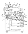
先ず、本発明の画像形成装置の一実施の形態の複写機の全体構成及び概略プロセスについて図1にて説明する。図1は、本発明にかかわる画像形成装置の一実施形態を示す電子写真方式を用いた複写機の概要断面図である。
【0012】
図1によれば、本実施の形態の複写機は、複写機本体の上部に自動原稿送り装置1を設けるとともに、複写機本体内に画像読取装置2、画像形成手段3、記録材収納手段4、搬送手段5、搬送部5B、排紙・反転手段6及び反転・再給紙手段7を有している。
【0013】
自動原稿送り装置1は、複写機本体の上部に設けられ、原稿を一枚ずつ送り出し、原稿の画像読取位置へと搬送し、画像読取が終わった原稿を排紙する装置である。自動原稿送り装置1は、原稿を載置する原稿載置台11、原稿載置台11上に載置された原稿を分離する原稿分離手段12、原稿分離手段12で分離された原稿を搬送する原稿搬送手段13、原稿搬送手段13で搬送された原稿を排紙する原稿排紙手段14、原稿排紙手段14によって排紙された原稿を受け止め、載置する原稿排紙台15、および、原稿の両面の画像を読み取る際に原稿の表裏を反転させるための原稿反転手段16を有している。
【0014】
原稿載置台11上に載置された複数枚の原稿は、原稿分離手段12によって分離され、1枚ずつ搬送される。原稿分離手段12によって分離・搬送された原稿は、原稿搬送手段13によって搬送され、下方に設けられた画像読取装置2によって、スリット21を通して、原稿の画像が読み取られる。画像が読み取られた原稿は、原稿排紙手段14によって、原稿排紙台15上へと排紙される。ところで、原稿の両面の画像を読み取る際には、画像が読み取られた原稿は、原稿反転手段16によって原稿の表裏が反転されて、再度、原稿搬送手段13によって搬送され、画像読取手段によって、スリット21を通して、原稿の裏面の画像が読み取られる。そして、裏面の画像が読み取られた原稿は、原稿排紙手段14によって、原稿排紙台15上へと排紙される。このような工程を、原稿載置台11上に載置された原稿の枚数分繰り返され、原稿の画像が読み取られる。
【0015】
また、自動原稿送り装置1は、一体に可倒式に構成されており、この自動原稿送り装置1を起こしてプラテンガラス22上を開放することにより、プラテンガラス22上に原稿を直接載置することができるように構成している。なお、本実施の形態では、原稿搬送手段13によって原稿を搬送しながら、原稿の画像を読み取るように構成しているが、原稿搬送手段13によって搬送された原稿をプラテンガラス22上に静止させた上で画像を読み取るように構成してもよい。
【0016】
画像読取装置2は、原稿の画像を読み取り画像データを得る手段であり、複写機本体内の上部に設けられている。この画像読取装置2は、自動原稿送り装置1の原稿搬送手段13によって搬送されている原稿の画像を読み取るためのスリット状の開口部であるスリット21、原稿を直接載置(静置)するための原稿台であるプラテンガラス22、原稿に光照射する光源であるランプ231と原稿からの反射光を反射させる第1ミラー232とを一体化している第1ミラーユニット23、第1ミラー232からの光を反射させる第2ミラー241と第3ミラー242とを一体化したVミラーユニット24と、スリット21上或いはプラテンガラス22上の原稿からの反射光を後述のCCD26に結像させる結像手段である結像レンズ25、および、結像レンズ25によって結像された光像を光電変換して画像情報を得る画像読取手段であるライン状のCCD26を有している。
【0017】
自動原稿送り装置1によって送られている原稿を、画像読取装置2で読み取る際は、第1ミラーユニット23及びVミラーユニット24は、図1において左方に移動し、第1ミラーユニット23がスリット21の下方に位置している。そして、原稿搬送手段13によってスリット21上を搬送されている原稿を、ランプ231で光照射し、原稿から反射した光は、第1ミラー232、第2ミラー241、第3ミラー242、結像レンズ25を介して、CCD26に入射する。CCD26では、入射した光を光電変換して、主走査方向(図1において紙面垂直方向)の原稿の画像を読み取り、一方、原稿が原稿搬送手段13によって副走査方向に移動されているので、原稿全面の画像を読み取ることができる。CCD26で読み取った画像情報は、適宜、画像処理が施され、後述するレーザー書込系33に供される。
【0018】
また、プラテンガラス22上に原稿が直接載置された場合は、第1ミラーユニット23とVミラーユニット24とを、プラテンガラスに沿って、図1において右方向に移動させながら、原稿の画像を読み取ることができる。
【0019】
画像形成手段3は、画像読取装置2で得た画像データに基づいて所定のプロセススピードで搬送されている記録材である記録紙上に画像形成する手段である。本実施の形態の画像形成手段3は、電子写真プロセスを用いて画像を形成するものである。画像形成手段3は、光導電性感光層を有しトナー像を担持する像担持体である感光体ドラム31と、感光体ドラム31を一様帯電させる帯電手段である帯電器32、CCD26で読み取った画像情報に基づいて、感光体ドラム31上を露光走査して潜像を形成する画像書込手段であるレーザー書込系33、感光体ドラム31上の潜像を現像してトナー像を形成する現像手段である現像器34、感光体ドラム31上に担持されたトナー像を、別途搬送されている記録紙上に転写する転写手段である転写器35、トナー像が転写された記録紙を感光体ドラム31上から分離する分離手段である分離器36、転写された後に感光体ドラム31上に残留したトナーを除去するクリーニング手段37、記録紙上のトナー像を定着する定着手段38を有している。そして、感光体ドラム31の周囲に、帯電器32、レーザー書込系33、現像器34、転写器35、分離器36、クリーニング手段37が配置されている。
【0020】
感光体ドラム31は、不図示の駆動手段によって、矢示の方向に回転し、帯電器32による一様帯電、レーザー書込系33による潜像形成、現像器34による現像がなされて、CCD26によって読み取られた画像情報に基づいたトナー像が形成される。
【0021】
記録材収納手段4は、複数枚の記録紙を積層状態で収納する記録材の収納手段である。本実施の形態では、記録材収納手段4として複数の記録材収納手段4A〜4Cを画像形成手段3及び後述する反転・再給紙手段7の下方に多段配置している。これら記録材収納手段4A〜4Cに収納される記録材としては、普通紙や再生紙など記録紙の他に、OHTなど種々の媒体が用いられる。
【0022】
また、搬送手段5は、記録材収納手段4から画像形成手段3へと記録材を搬送する搬送手段であり、各記録材収納手段4A〜4Cそれぞれに収納された記録紙を、中間搬送ローラ541〜543を通して搬送部5Bへと搬送できるように構成している。
【0023】
搬送部5Bは、後段において詳述する第2ループ形成ローラ55とレジストローラ56とにより構成される第2曲がり修正手段を有するもので、第2ループ形成ローラ55から感光体ドラム31の転写位置に至る記録紙の給送経路であり、第2ループ形成ローラ55とレジストローラ56と必要に応じて設けられるドラム前搬送ローラ39とにより搬送部5Bが構成される。中間搬送ローラ541或いは再給紙中間搬送ローラ741により搬送される記録紙を搬送部5Bを通して画像形成手段3へと給送する。
【0024】
記録材である記録紙が何れかの記録材収納手段4A〜4Cより、ピックアップローラ51A〜51Cにより送り出され、中間搬送ローラ541を経てレジストローラ56へ搬送される。
【0025】
記録紙は、レジストローラ56の駆動によって、感光体ドラム31上に担持されたトナー像との同期がとられ、転写器35が配設される感光体ドラム31の転写域へ給送される。
【0026】
感光体ドラム31上に形成されたトナー像が、転写器35によって記録紙に一方の面(記録紙表面)に転写される。トナー像(表面トナー像)が一方の面に転写された記録紙は、分離器36によって感光体ドラム31上から分離され、定着手段38へと搬送され、そこで、加熱、加圧作用により、トナー像が記録紙に定着される。一方、トナー像が記録紙へ転写された感光体ドラム31は、さらに回転を続け、クリーニング手段37によって、感光体ドラム31上に残留したトナーが除去され、次の画像形成へと供される。
【0027】
なお、本実施の形態では、感光体ドラム31とレジストローラ56との間の感光体ドラム31近傍に、レジストローラ56から送り出された記録紙を搬送するドラム前搬送ローラ39が設けられており、記録紙の搬送力アップに寄与させている。また、分離器36と定着手段38との間には、分離器36によって分離された記録紙を搬送するために、記録紙の下面側(画像形成された側とは反対側)を支持し、搬送する搬送ローラ(符号なし)及びベルト(符号なし)を設けている。
【0028】
排紙・反転手段6は、搬送手段5及び搬送部5Bによって搬送された記録紙上に、画像形成手段3で画像形成された記録紙を、排紙或いは後述する反転・再給紙手段7へ再給紙するための手段である。この排紙・反転手段6は、トナー像が定着された記録紙を定着手段38から排出する定着排出ローラ61、定着排出ローラ61により排出された記録紙をそのまま機外へ排出する場合と表裏反転させた後排出する或いは裏面に画像形成するために再給紙する場合とで搬送路を切り替える切替手段62、記録紙を機外に排出するための排紙ローラ63、複写機の側面に設けられ排紙ローラ63により排出された記録紙を積載する排紙トレイ64、排紙される記録紙の表裏を反転、或いは記録紙を反転・再給紙手段7へと搬送させる、排紙・反転ローラ65及び排紙・反転搬送ローラ651,652を有している。また、S1は記録紙の反転排紙の際の記録紙後端を検知するために、記録紙の搬送方向で排紙・反転ローラ65の直前に配置される、例えばフォトカプラよりなる記録紙検知手段である。
【0029】
画像形成された記録紙をそのまま、すなわち、画像形成された面を上側にして排出する場合は、切替手段62を図1において一点鎖線で示す位置に位置させ、定着排出ローラ61、排紙ローラ63によって、機外の排紙トレイ64へと排出する。また、画像形成された記録紙の表裏を反転させて排紙(反転排紙)、すなわち、画像形成された面を下側にして排出する場合は、切替手段62を図1において実線で示す位置に位置させ、定着排出ローラ61により搬送される記録紙を、一旦、排紙・反転ローラ65により搬送し、搬送される記録紙の後端が記録紙検知手段S1により検知されると、排紙・反転ローラ65の回転方向を逆転させて記録紙を搬送し、排紙ローラ63によって機外の排紙トレイ64へと排出する。
【0030】
続けて、記録紙の裏面に画像形成する際(両面画像形成の際)に、切替手段62を図1において実線で示す位置に位置させ、定着排出ローラ61により搬送される記録紙を、排紙・反転ローラ65の方向に搬送し、排紙・反転ローラ65及び排紙・反転搬送ローラ651,652によって反転・再給紙手段7へと搬送する。この際、記録紙の搬送速度は両面コピーの生産性を上げるため、前記所定のプロセススピードより高速にて搬送される。
【0031】
反転・再給紙手段7は排紙・反転手段6より搬送された記録紙をスイッチバックさせる再給紙反転部7Aと、再給紙反転部7Aにより反転されて搬送させる記録紙を、前述した搬送部5Bへと再給紙する再給紙搬送部7Bとにより構成される手段である。再給紙反転部7Aには、再給紙反転ローラ71と、記録紙の搬送方向で再給紙反転ローラ71の直前に配置され、記録紙の反転再給紙の際の記録紙後端を検知するための、例えばフォトカプラを用いた記録紙検知手段S2が設けられる。
【0032】
再給紙反転部7Aは排紙・反転手段6の排紙・反転ローラ65及び排紙・反転搬送ローラ651,652により高速に搬送された記録紙を、一旦、再給紙反転ローラ71により高速に搬送し、搬送される記録紙の後端が記録紙検知手段S2により検知されると、再給紙反転ローラ71の回転方向を逆転させると共に、搬送速度を所定のプロセススピードとして記録紙を再給紙搬送部7Bへと搬送する。
【0033】
再給紙搬送部7Bは、後段において詳述する第1ループ形成ローラ72とプレレジストローラ73とにより構成される第1曲がり修正手段を有するもので、再給紙反転部7Aの再給紙反転ローラ71よりの記録紙の搬送を受ける再給紙搬送ローラ751から第1ループ形成ローラ72とプレレジストローラ73とを通して第2ループ形成ローラ55に至る記録紙の再給紙搬送経路であり、記録紙の搬送方向に対して、必要に応じて複数組設けられる再給紙搬送ローラ751,752と第1ループ形成ローラ72とプレレジストローラ73と必要により設けられる再給紙中間搬送ローラ741とにより再給紙搬送部7Bが構成される。
【0034】
再給紙反転部7Aの再給紙反転ローラ71よりの記録紙が、再給紙搬送部7Bに設けられる再給紙搬送ローラ751,752と第1ループ形成ローラ72とプレレジストローラ73と再給紙中間搬送ローラ741とを通して第2ループ形成ローラ55に合流し、記録紙収納手段4からの給紙と同様に、再度搬送部5Bを通して画像形成手段3へと搬送され、感光体ドラム31上に形成された裏面トナー像が、転写器35によって記録紙の他方の面(記録紙裏面)に転写される。裏面トナー像が他方の面に転写された記録紙は、分離器36によって感光体ドラム31上から分離され、定着手段38へと搬送され、そこで、再度加熱、加圧作用により、記録紙上の裏面トナー像が定着されて両面画像が形成され、前述した排紙・反転手段6を経て排紙トレイ64に排紙される。一方、裏面トナー像が記録紙へ転写された感光体ドラム31は、さらに回転を続け、クリーニング手段37によって、感光体ドラム31上に残留したトナーが除去され、次の画像形成へと供される。
【0035】
なお、上記の説明において、記録紙を搬送する各ローラ対は、駆動及び従動の一対のローラにより構成され、それぞれ不図示の制御手段による駆動信号に基づき駆動される駆動手段(不図示)により回転、駆動される。
【0036】
上記の如くにして表裏のトナー像を記録紙の両面に形成する両面画像形成が行われるが、複数枚の両面コピーを行う場合、感光体ドラム31の分離位置より再給紙搬送部7Bまでの間に位置され得る枚数、本実施の形態においては、先ず3〜5枚(例えばA−4横送りの場合に5枚、A−3縦送りの場合で3枚)程度の記録紙上への表面画像形成が連続して行われて、感光体ドラム31の分離位置より再給紙搬送部7Bまでの間に位置され、続いて感光体ドラム31の分離位置より再給紙搬送部7Bまでの間に位置される枚数の記録紙の裏面画像形成が連続して行われ、この繰り返しにより複数枚の両面コピーが行われる。勿論、感光体ドラム31の分離位置より再給紙搬送部7Bまでの間の長さにより1回の処理枚数が決められる。
【0037】
しかしながら、上記の如き両面画像を形成する画像形成装置においては、定着後、両面画像形成のために排紙・反転手段6を経て、再給紙反転部7Aで反転、再給紙搬送部7Bで再給紙する反転・再給紙手段7迄の記録材の搬送経路が長くなるので、記録紙と搬送ガイド(符号なし)との摩擦抵抗の増大や記録紙と排紙・反転手段6や反転・再給紙手段7の各ローラとのスベリの増大等の原因により、画像形成手段3の手前近傍に配置されるレジストローラ56に記録紙が到達する以前に大きい紙曲がりが発生し、レジストローラ56での紙曲がりの修正では修正しきれなくなってしまい、記録紙上の正確な位置に裏面トナー像を形成することが困難となる。この紙曲がりは排紙・反転手段6及び再給紙反転部7Aの高速化や装置の高速化が図られるほど、また定着後の排紙・反転手段6及び再給紙反転部7Aの搬送経路が長いほど更に顕著になってしまう。
【0038】
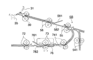
この為、両面コピーの際に、再給紙搬送部7B及び搬送部5Bにおいて、記録紙の曲がり修正を行う。図2ないし図5により再給紙搬送部7B及び搬送部5Bでの記録紙の曲がり修正を説明する。図2は、図1の再給紙搬送部及び搬送部の部分拡大断面図であり、図3は、再給紙搬送部に設けられる第1曲がり修正手段での記録材の搬送を示す説明図であり、図4は、搬送部に設けられる第2曲がり修正手段での記録材の搬送を示す説明図であり、図5は、第1曲がり修正手段での第1突き当て手段の調整を示す図である。
【0039】
図2ないし図4によれば、前述したように、記録紙は再給紙搬送部7Bを通して第2ループ形成ローラ55に合流し、再度搬送部5Bを通して画像形成手段3へと搬送され、感光体ドラム31上に形成された裏面トナー像が、転写器35によって記録紙の他方の面(記録紙裏面)に転写され両面画像形成が行われる。
【0040】
再給紙搬送部7Bは、第1曲がり修正手段を有するもので、再給紙反転部7Aの再給紙反転ローラ71よりの記録紙の搬送を受ける再給紙搬送ローラ751から第1ループ形成ローラ72とプレレジストローラ73とを通して第2ループ形成ローラ55に至る記録紙の再給紙搬送経路であり、記録紙の搬送方向に対して、必要に応じて複数組設けられる再給紙搬送ローラ751,752(図1参照)と第1ループ形成ローラ72とプレレジストローラ73と必要により設けられる再給紙中間搬送ローラ741とにより再給紙搬送部7Bが構成される。
【0041】
第1曲がり修正手段は、第1突き当て手段であるプレレジストローラ73と、第1ループ形成手段である第1ループ形成ローラ72とから構成され、搬送される記録紙にループを形成して紙曲がりの修正を行う手段である。さらに、本実施の形態では、このループ形成を確実に行わせるために、第1ループ形成ローラ72とプレレジストローラ73との間に、記録紙の搬送を案内する案内部材(ループ形成ガイド)として、上ガイド781及び下ガイド782を設けている。本実施の形態では、上ガイド781を断面形状(図1、2のように見た場合)で山形に構成して、この上ガイド781に沿ったループ形状に、記録紙を案内するループ形成ガイドとして機能させている。
【0042】
第1ループ形成ローラ72は、再給紙搬送ローラ751,752(図1参照)により搬送された記録紙を搬送する手段である。この第1ループ形成ローラ72は、一対の対向ローラによって構成されており、図示しない駆動手段によって矢示の方向に回転可能に、再給紙搬送部7Bの再給紙搬送経路上に設けられている。
【0043】
プレレジストローラ73は、第1ループ形成ローラ72により搬送された記録紙を一旦突き当てた後搬送を再開させる第1突き当て手段であり、いわゆる、レジストローラである。このプレレジストローラ73は、一対の対向ローラによって構成されており、図示しない駆動手段によって矢示の方向に回転可能に、再給紙搬送部7Bの再給紙搬送経路上に設けられている。
【0044】
再給紙搬送部7Bでの記録紙の搬送動作としては、図3に示すように、再給紙搬送部7Bの再給紙経路上において、再給紙搬送ローラ751,752(図1参照)から第1ループ形成ローラ72に搬送される太線で示す記録紙が、回転する第1ループ形成ローラ72により搬送される(図3(A))。プレレジストローラ73は、記録紙が第1ループ形成ローラ72によって搬送されてきたときには、回転を停止しており、このため、搬送されてきた記録紙は、一旦、レジストローラ56に突き当たり、その先端が停止せしめられる。プレレジストローラ73に記録紙が突き当たった後も、第1ループ形成ローラ72による記録紙の搬送は継続される(図3(B))。従って、プレレジストローラ73によって先端が停止させられた記録紙は、更なる第1ループ形成ローラ72の回転による搬送により、図3(C)に示すように、プレレジストローラ73と第1ループ形成ローラ72との間にループが形成される。このとき、形成されるループは、上下ガイド781,782によって、適正な形状で確実に形成されるとともに、十分なループを形成することができ、プレレジストローラ73に突き当てられて記録紙の曲がり修正を確実に行うことができる。特に、定着後、両面画像形成のために排紙・反転手段を経て、再給紙反転部で反転、再給紙搬送部で再給紙する反転・再給紙手段迄の記録材の長い搬送経路での、記録材と搬送ガイドとの摩擦抵抗の増大や記録材と搬送ローラのスベリの増大等の原因により発生する大きい紙曲がりを、第1曲がり修正手段にて一旦修正する。そして、前記のループが第1ループ形成ローラ72とプレレジストローラ73との間に形成されると同時に、不図示の制御手段によるプレレジスト再スタート信号に基づいて、プレレジストローラ73の回転が開始され、第1ループ形成ローラ72、及び、本実施の形態においては感光体ドラム31の分離位置より再給紙搬送部7Bまでの間に位置される記録紙を搬送するローラ対の全てが回転されたままで、またループ形成が成されたままの状態でプレレジストローラ73により記録紙が搬送され、再給紙中間搬送ローラ741によって再度搬送部5Bへと搬送される(図3(D))。従って、記録紙が停止されることなく再給紙搬送部7Bの再給紙経路を搬送されることとなる。前記第1曲がり修正手段による記録紙の曲がりを修正することにより、再給紙中間搬送ローラ741から搬送部5Bへの経路での搬送ガイド(符号なし)での記録紙の搬送中のジャムをも防止する。
【0045】
なお、本実施の形態では、記録紙を突き当てる第1突き当て手段と記録紙の曲がりを修正する第1曲がり修正手段の一部とを、このプレレジストローラ73で兼用する構成として、部品点数を減らしているが、それぞれの機能を分けて設けても良い。この場合、記録紙の付き当てのみを行わせている場合は、ローラ対で構成することなく、例えば、再給紙経路を遮ることが可能なシャッターやストッパーなどを第1突き当て手段としてもよい。
【0046】
搬送部5Bは、第2曲がり修正手段を有するもので、第2ループ形成ローラ55から感光体ドラム31の転写位置に至る記録紙の給送経路であり、第2ループ形成ローラ55とレジストローラ56と必要に応じて設けられるドラム前搬送ローラ39とにより搬送部5Bが構成される。この裏面画像形成の際には、再給紙中間搬送ローラ741により搬送される記録紙を搬送部5Bを通して画像形成手段3へと給送する。
【0047】
第2曲がり修正手段は、第2突き当て手段であるレジストローラ56と、第2ループ形成手段である第2ループ形成ローラ55とから構成され、搬送される記録紙にループを形成して紙曲がりの修正を行う手段である。さらに、本実施の形態では、このループ形成を確実に行わせるために、第2ループ形成ローラ55とレジストローラ56との間に、記録紙の搬送を案内する案内部材(ループ形成ガイド)として、上ガイド581及び下ガイド582を設けている。本実施の形態では、上ガイド581を断面形状(図1、2のように見た場合)で山形に構成して、この上ガイド581に沿ったループ形状に、記録紙を案内するループ形成ガイドとして機能させている。
【0048】
第2ループ形成ローラ55は、この裏面画像形成の際には、再給紙中間搬送ローラ741により搬送された記録紙を搬送する手段である。なお、記録材収納手段4より記録紙が給送される際には中間搬送ローラ541により搬送された記録紙を搬送する。この第2ループ形成ローラ55は、一対の対向ローラによって構成されており、図示しない駆動手段によって矢示の方向に回転可能に、搬送部5Bの給送経路上に設けられている。
【0049】
レジストローラ56は、第2ループ形成ローラ55により搬送された記録紙を一旦突き当てた後搬送を再開させる第2突き当て手段である。このレジストローラ56は、一対の対向ローラによって構成されており、図示しない駆動手段によって矢示の方向に回転可能に、搬送部5Bの給送経路上に設けられている。
【0050】
搬送部5Bでの記録紙の搬送動作としては、図4に示すように、搬送部5Bの給送経路上において、再給紙搬送部7Bの再給紙中間搬送ローラ741(図2参照)から第2ループ形成ローラ55に搬送される太線で示す記録紙が、回転する第2ループ形成ローラ55により搬送される(図4(A))。レジストローラ56は、記録紙が第2ループ形成ローラ55によって搬送されてきたときには、回転を停止しており、このため、搬送されてきた記録紙は、一旦、レジストローラ56に突き当たり、その先端が停止せしめられる。レジストローラ56に記録紙が突き当たった後も、第2ループ形成ローラ55による記録紙の搬送は継続される(図4(B))。従って、レジストローラ56によって先端が停止させられた記録紙は、更なる第2ループ形成ローラ55の回転による搬送により、図4(C)に示すように、レジストローラ56と第2ループ形成ローラ55との間にループが形成される。このとき、形成されるループは、上下ガイド581,582によって、適正な形状で確実に形成されるとともに、十分なループを形成することができ、レジストローラ56に突き当てられて記録紙の曲がり修正をさらに確実に行うことができる。特に、定着後、両面画像形成のために排紙・反転手段を経て、再給紙反転部で反転、再給紙搬送部で再給紙する反転・再給紙手段迄の記録材の長い搬送経路での、記録材と搬送ガイドとの摩擦抵抗の増大や記録材と搬送ローラのスベリの増大等の原因により発生する大きい紙曲がりの、第1曲がり修正手段にて修正しきれなかった紙曲がりをさらに修正する。そして、前記のループが第2ループ形成ローラ55とレジストローラ56との間に形成されると同時に、不図示の制御手段によるレジスト再スタート信号に基づいてレジストローラ56の回転が開始され、第2ループ形成ローラ55及び中間搬送ローラ541が回転されたままで、またループ形成が成されたままの状態でレジストローラ56により記録紙が搬送され、ドラム前搬送ローラ39(図2参照)を通して再度画像形成手段3へと搬送される(図4(D))。従って、記録紙が停止されることなく搬送部5Bの給送経路を搬送されることとなる。そして、レジストローラ56から送り出された記録紙に同期せしめて、レーザー書込系33による裏面画像の潜像形成が開始され、記録紙と感光体ドラム31上の裏面トナー像との同期がとられる。このように、記録紙をレジストローラ56に一旦突き当てることにより、記録紙の先端のタイミングを正確に採ることができ、搬送のバラツキを押さえることができるとともに、レーザー書込系33の同期が採りやすくなり、記録紙上に正確な位置で画像形成が可能となる。また、前記第2曲がり修正手段により記録紙の曲がりを修正することによって、第1曲がり修正手段にて修正しきれなかった紙曲がりをさらに修正し、裏面画像の記録紙上での位置合わせを正確なものとする。
【0051】
記録材収納手段4より中間搬送ローラ541を通しての記録紙の給送の際にも上記図4にて説明したと同様な記録紙の給送方法が採られても良いが、本実施の形態においては図1にて前述したように、記録材収納手段4より中間搬送ローラ541を通しての記録紙の給送の際には、ループ形成状態のままでレジストローラ56、第2ループ形成ローラ55及び中間搬送ローラ541を一旦停止し、不図示の制御手段によるレジスト再スタート信号に基づく、レジストローラ56、第2ループ形成ローラ55及び中間搬送ローラ541の駆動によって、感光体ドラム31上に担持されたトナー像との同期がとられ、転写器35が配設される感光体ドラム31の転写域へ給送される。
【0052】
なお、本実施の形態では、記録紙を突き当てる第2突き当て手段と記録紙の曲がりを修正する第2曲がり修正手段の一部とを、このレジストローラ56で兼用する構成として、部品点数を減らしているが、それぞれの機能を分けて設けても良い。この場合、記録紙の付き当てのみを行わせている場合は、ローラ対で構成することなく、例えば、給送経路を遮ることが可能なシャッターやストッパーなどを第2突き当て手段としてもよい。
【0053】
また、再給紙搬送部7Bでの第1曲がり修正手段としては、図5に示すように、第1曲がり修正手段の第1突き当て手段であるプレレジストローラ73のローラ対と、案内部材(ループ形成ガイド)としての、上ガイド781及び下ガイド782と、を記録紙の搬送方向に直交する方向に長い、L字状の板状部材76に取付けたユニット構成とし、例えば板状部材76の一方の側を基準(固定支点)として、記録紙の搬送方向に直交して他方の側を数mm、例えば2〜3mm、図5に矢印で示すように板状部材76を移動可能とし、組立時に、予め測定される、定着後、両面画像形成のために排紙・反転手段を経て、再給紙反転部で反転、再給紙搬送部で再給紙する反転・再給紙手段迄の記録材の長い搬送経路で生じる紙曲がり癖等の、第1曲がり修正手段と第2曲がり修正手段とで修正が必要な紙曲がり量を予め計測しておき、第1曲がり修正手段を記録紙の搬送方向に直交して配設した場合の第1曲がり修正手段では修正しきれぬ際に、例えば第2曲がり修正手段位置での紙曲がり修正量が2mm必要な場合、第1曲がり修正手段を1mm程度記録紙の搬送方向に直交して傾けて調整して固定し、第2曲がり修正手段にて修正可能な残りの量(第2曲がり修正手段では修正しきれぬ量)、例えば1mmを第2曲がり修正手段にて修正するようにする。これにより、裏面画像形成時に、定着後、両面画像形成のために排紙・反転手段を経て、再給紙反転部で反転、再給紙搬送部で再給紙する反転・再給紙手段迄の記録材の長い搬送経路で生じる紙曲がりが、第1曲がり修正手段及び第2曲がり修正手段により確実に修正されると共に、紙曲がり修正量の幅も大きくすることが可能となる。
【0054】
なお上記において、第1突き当て手段であるプレレジストローラ73のローラ対のみを調整可能としてもよい。
【0055】
上記の如く、本発明により、裏面画像形成時に、定着後、両面画像形成のために排紙・反転手段を経て、再給紙反転部で反転、再給紙搬送部で再給紙する反転・再給紙手段迄の記録材の長い搬送経路で生じる紙曲がりが、第1曲がり修正手段及び第2曲がり修正手段により確実に修正され、記録材上の正確な位置に裏面トナー像が形成されて、良好な両面画像形成が行われる。
【0056】
なお上記効果は、第1突き当て手段及び第2突き当て手段のみの構成によっても、或いはさらに第1突き当て手段、第2突き当て手段の少なくとも何れか一方にループ形成ガイド及びループ形成手段(第1ループ形成手段或いは第2ループ形成手段)を加えた構成としたものによっても達成されるものであり、これらの構成も本発明に含まれることは勿論である。
【0057】
【発明の効果】
本発明によれば、反転・再給紙手段を搬送される記録材の先端の紙曲がりを修正して、記録材上の正確な位置に裏面トナー像を形成し、良好な両面画像形成が行われる。
【図面の簡単な説明】
【図1】本発明にかかわる画像形成装置の一実施形態を示す電子写真方式を用いた複写機の概要断面図である。
【図2】図1の再給紙搬送部及び搬送部の部分拡大断面図である。
【図3】再給紙搬送部に設けられる第1曲がり修正手段での記録材の搬送を示す説明図である。
【図4】搬送部に設けられる第2曲がり修正手段での記録材の搬送を示す説明図である。
【図5】第1曲がり修正手段での第1突き当て手段の調整を示す図である。
【符号の説明】
1 自動原稿送り装置
2 画像読取装置
3 画像形成手段
4 記録材収納手段
5 搬送手段
5B 搬送部
6 排紙・反転手段
7 反転・再給紙手段
7A 再給紙反転部
7B 再給紙搬送部
55 第2ループ形成ローラ
56 レジストローラ
72 第1ループ形成ローラ
73 プレレジストローラ
581,781 上ガイド
582,782 下ガイド[0001]
BACKGROUND OF THE INVENTION
The present invention includes a recording material storage unit that stores a recording material, an image forming unit that forms an image on the recording material, a transport unit that transports the recording material from the recording material storage unit to the image forming unit, and a recording Image forming apparatus capable of forming an image on both sides of a transfer material by providing a refeed / refeed unit having a refeed reversing unit and a refeed conveyance unit for forming an image on both sides of the material About.
[0002]
[Prior art]
Conventionally, a recording material storing means for storing a recording material, an image forming means for forming an image on the recording material, a transport unit for transporting the recording material from the recording material storing means to the image forming means, and both surfaces of the recording material An image forming apparatus for forming an image on both sides of a transfer material by providing a reversing / refeeding unit having a refeeding reversing unit and a refeeding conveyance unit for forming an image includes a copying machine, a printer, and Widely used in facsimiles. Among such image forming apparatuses, for example, an image forming apparatus that forms an image by an electrophotographic method includes an image forming unit such as a charging unit, an image writing unit, and a developing unit disposed around the image carrier, After the image carrier is uniformly charged by the charging unit using the image forming unit, an electrostatic latent image is formed on the image carrier by image writing (image exposure) of the image writing unit, and the latent image is Development is performed with a developer contained in the developing unit to form a visible toner image, and the toner image is transferred to one side of the recording material conveyed through the conveying unit from the recording material storage unit to form a toner image on the recording material. After fixing the toner image on one side of the recording material by the fixing means, the recording material is conveyed to the reversing / refeeding means through the paper discharge / reversing means, and the refeeding of the reversing / refeeding means is performed. Transport to the image forming means through the reversing unit, the re-feed transport unit and the transport unit again, Performs toner image formed on the other surface of the recording material by the image forming means, and is configured as to form a double-sided image by fixing the toner image on the other surface of the recording material by a fixing means.
[0003]
In such an image forming apparatus, in general, a recording material conveyed from a recording material storage unit through a conveyance unit, and a refeed reversing unit of a paper discharge / reversing unit and a reversing / refeeding unit for double-sided image formation, In order to synchronize the timing of the recording material conveyed through the refeed conveyance unit and the conveyance unit again with the image formation by the image forming unit, a registration roller for temporarily stopping the recording material near the image forming unit is provided. ing. The recording material is once abutted against the registration roller to stop the recording material, and the recording material conveyance and the image formation are synchronized with each other. Further, the registration roller is configured so that the bending of the leading end of the recording material can be corrected by forming a loop in the recording material after the recording material is temporarily stopped.
[0004]
As described above, the registration roller disposed in front of the image forming unit matches the timing of the recording material and image formation, and corrects the bending of the leading end of the recording material to be conveyed, thereby correcting the recording material on the recording material. A double-sided image is formed at an accurate position.
[0005]
[Problems to be solved by the invention]
By the way, in recent years, an improvement in the number of copies per unit time (improvement in productivity) has been demanded in smaller image forming apparatuses, and higher speed has been achieved. For this reason, attempts have been made to improve each part of the image forming apparatus and more strictly control the paper conveyance. However, there are problems such as an increase in the cost of the image forming apparatus and a decrease in reliability due to complicated control. Not improved.
[0006]
That is, in the image forming apparatus that forms a double-sided image as described above, after fixing, it passes through a paper discharge / reversing unit for double-sided image formation, reverses at a refeeding reverse unit, and refeeds at a refeeding transport unit. The recording material has a long conveying path to the reversing / refeeding means, and the recording material is transferred to the registration roller due to an increase in frictional resistance between the recording material and the conveying guide or an increase in sliding between the recording material and the conveying roller. A large paper curl occurs in the transport path of the paper discharge / reversing unit and reversing / refeeding unit before it arrives, and it is corrected by correcting the paper curl at the registration roller located near the image forming unit. This causes a problem that it is difficult to form a back toner image at an accurate position on the recording material. This paper bending becomes more prominent as the speed of the apparatus is increased, and as the transport path of the paper discharge / reversing means and the reversing / refeeding means is longer.
[0007]
The present invention solves the above problems, corrects the bending of the recording material conveyed through the reversing / refeeding means, forms a backside toner image at an accurate position on the recording material, and provides a good double-sided image. An object of the present invention is to provide an image forming apparatus capable of forming images.
[0008]
[Means for Solving the Problems]
The above-mentioned object is a recording material storage means for storing a recording material,SaidImage forming means for forming an image on a recording material, and the recording material storage meansSaidA transport unit for transporting the recording material to the image forming unit;SaidA refeed / refeed unit having a refeed reversing unit and a refeed transport unit for forming an image on both sides of the recording material;
Conveyed from the recording material storage means through the conveying section.RuAfter the image forming unit forms an image on one surface of the recording material, the recording material is conveyed to the reversing / refeeding unit, and again with the refeeding conveyance unit of the reversing / refeeding unit. In the image forming apparatus that transports to the image forming unit through the transport unit and forms an image on the other surface of the recording material by the image forming unit.
In the refeed conveyance section of the reversing / refeed means,SaidProviding a first bend correcting means for correcting the bend of the recording material to be conveyed;
In the transport unit disposed in the vicinity of the image forming unit,SaidSecond bending correcting means for correcting the bending of the recording material being conveyed is provided.And
The first bend correcting means includes a first abutting means for temporarily stopping the conveyed recording material by abutting a leading end of the conveyed recording material, and a temporary stop of the conveyed recording material. 1st loop formation means which forms a loop in the said recording material conveyed, and said 1st abutting means is provided in the conveyance direction downstream of the said recording material conveyed with respect to said 1st loop formation means. And
The second bend correcting means includes a second abutting means for temporarily stopping the conveyed recording material by abutting a leading end of the conveyed recording material, and a temporary stop of the conveyed recording material. A second loop forming unit for forming a loop in the recording material to be conveyed; and the second abutting unit is provided on the downstream side in the conveying direction of the recording material to be conveyed with respect to the second loop forming unit. And
The first bend correcting unit and the second bend correcting unit are configured to form a loop on the recording material to be conveyed after temporarily stopping the recording material to be conveyed, so that the leading end of the recording material to be conveyed It is a bend correction means to correct the bendAchieved by an image forming apparatus characterized byThe
[0010]
DETAILED DESCRIPTION OF THE INVENTION
Embodiments of the present invention will be described below. The description in this column does not limit the technical scope of the claims or the meaning of terms. In addition, the following assertive description in the embodiment of the present invention shows the best mode, and does not limit the meaning or technical scope of the terms of the present invention.
[0011]
First, the overall configuration and schematic process of a copying machine according to an embodiment of the image forming apparatus of the present invention will be described with reference to FIG. FIG. 1 is a schematic sectional view of a copying machine using an electrophotographic system showing an embodiment of an image forming apparatus according to the present invention.
[0012]
According to FIG. 1, the copying machine of the present embodiment is provided with an automatic document feeder 1 at the top of the copying machine main body, and an
[0013]
The automatic document feeder 1 is an apparatus that is provided on the upper part of the copying machine main body, feeds documents one by one, conveys them to the image reading position, and discharges the document after image reading. The automatic document feeder 1 includes a document placing table 11 for placing a document, a
[0014]
A plurality of documents placed on the document placing table 11 are separated by the document separating means 12 and conveyed one by one. The document separated and transported by the
[0015]
Further, the automatic document feeder 1 is configured to be integrally retractable, and the document is directly placed on the
[0016]
The
[0017]
When the document fed by the automatic document feeder 1 is read by the
[0018]
When the document is placed directly on the
[0019]
The image forming unit 3 is a unit that forms an image on a recording sheet that is a recording material conveyed at a predetermined process speed based on the image data obtained by the
[0020]
The
[0021]
The recording material storage means 4 is a recording material storage means for storing a plurality of recording sheets in a stacked state. In the present embodiment, a plurality of recording
[0022]
The
[0023]
The
[0024]
The recording paper as the recording material is sent out from any of the recording material storage means 4A to 4C by the
[0025]
The recording paper is synchronized with the toner image carried on the
[0026]
The toner image formed on the
[0027]
In the present embodiment, a
[0028]
The paper discharge / reversing unit 6 discharges the recording paper on which the image is formed by the image forming unit 3 onto the recording paper transported by the
[0029]
When the image-formed recording sheet is discharged as it is, that is, with the image-formed surface facing up, the switching means 62 is positioned at the position indicated by the alternate long and short dash line in FIG. As a result, the sheet is discharged to a
[0030]
Subsequently, when forming an image on the back side of the recording paper (when forming a double-sided image), the switching
[0031]
The reversing / refeeding unit 7 switches the refeeding reversing unit 7A for switching back the recording paper conveyed by the paper discharging / reversing unit 6 and the recording paper to be reversed and conveyed by the refeeding reversing unit 7A. It is a means constituted by a
[0032]
The refeed reversing section 7A temporarily feeds the recording paper conveyed at high speed by the paper ejection / reversing
[0033]
The
[0034]
The recording paper from the
[0035]
In the above description, each roller pair for conveying the recording paper is composed of a pair of driving and driven rollers, and each is rotated by a driving means (not shown) driven based on a driving signal from a control means (not shown). Driven.
[0036]
As described above, double-sided image formation is performed in which the front and back toner images are formed on both sides of the recording paper. However, when performing double-sided copying of a plurality of sheets, from the separation position of the
[0037]
However, in the image forming apparatus that forms a double-sided image as described above, after fixing, it passes through the paper discharge / reverse means 6 for double-sided image formation, and is reversed by the refeed reversing unit 7A and re-feeding and transporting
[0038]
For this reason, at the time of duplex copying, the
[0039]
2 to 4, as described above, the recording paper merges with the second
[0040]
The
[0041]
The first bend correcting means is composed of a
[0042]
The first
[0043]
The
[0044]
As shown in FIG. 3, the recording paper transporting operation in the paper
[0045]
In the present embodiment, the
[0046]
The
[0047]
The second bending correcting means is composed of a
[0048]
The second
[0049]
The
[0050]
As shown in FIG. 4, the recording sheet is transported by the
[0051]
The recording paper feeding method similar to that described above with reference to FIG. 4 may also be adopted when feeding the recording paper from the recording material storage means 4 through the
[0052]
In the present embodiment, the
[0053]
Further, as the first bend correction means in the
[0054]
In the above description, only the roller pair of the
[0055]
As described above, according to the present invention, at the time of backside image formation, after fixing, the paper is fed through a paper discharge / reversing unit for double-sided image formation, reversed at the refeeding reversing unit, and reversed at the refeeding conveyance unit. The paper bend generated in the long conveyance path of the recording material to the re-feeding means is reliably corrected by the first bend correcting means and the second bend correcting means, and a back toner image is formed at an accurate position on the recording material. Good double-sided image formation is performed.
[0056]
Note that the above effect can be achieved by the configuration of only the first abutting means and the second abutting means, or at least one of the first abutting means and the second abutting means. The present invention can also be achieved by a configuration in which one loop forming means or second loop forming means) is added, and these configurations are of course included in the present invention.
[0057]
【The invention's effect】
According to the present invention, the recording material conveyed through the reversing / refeeding meansTipBy correcting the paper skew, a back toner image is formed at an accurate position on the recording material, and good double-sided image formation is performed.
[Brief description of the drawings]
FIG. 1 is a schematic cross-sectional view of a copying machine using an electrophotographic system showing an embodiment of an image forming apparatus according to the present invention.
2 is a partially enlarged cross-sectional view of a refeed conveyance unit and a conveyance unit in FIG. 1; FIG.
FIG. 3 is an explanatory diagram illustrating conveyance of a recording material by a first bend correction unit provided in a refeed conveyance unit.
FIG. 4 is an explanatory diagram illustrating conveyance of a recording material by a second bend correction unit provided in a conveyance unit.
FIG. 5 is a diagram showing adjustment of the first abutting means by the first bend correcting means.
[Explanation of symbols]
1 Automatic document feeder
2 Image reader
3 Image forming means
4 Recording material storage means
5 Transport means
5B Transport section
6 Paper discharge / reversing means
7 Reverse / Refeeding means
7A Refeed reversing section
7B Re-feed transport unit
55 Second loop forming roller
56 Registration Roller
72 First loop forming roller
73 Pre-registration roller
581,781 Upper guide
582,782 Lower guide
Claims (4)
前記記録材収納手段より前記搬送部を通して搬送される記録材の一方の面に前記画像形成手段により画像形成を行なった後、前記記録材を前記反転・再給紙手段へと搬送し、前記反転・再給紙手段の再給紙搬送部と再び前記搬送部とを通して前記画像形成手段へと搬送し、前記画像形成手段により前記記録材の他方の面に画像形成を行なう画像形成装置において、
前記反転・再給紙手段の再給紙搬送部に、前記搬送される記録材の曲がりを修正する第1曲がり修正手段を設けると共に、
前記画像形成手段近傍に配設される前記搬送部に、前記搬送される記録材の曲がりを修正する第2曲がり修正手段を設けるものであって、
前記第1曲がり修正手段は、前記搬送される記録材の先端が突き当てられて前記搬送される記録材を一旦停止させる第1突き当て手段と、前記搬送される記録材を一旦停止させた後に前記搬送される記録材にループを形成する第1ループ形成手段を有し、前記第1突き当て手段は、前記第1ループ形成手段に対して前記搬送される記録材の搬送方向下流側に設けられ、
前記第2曲がり修正手段は、前記搬送される記録材の先端が突き当てられて前記搬送される記録材を一旦停止させる第2突き当て手段と、前記搬送される記録材を一旦停止させた後に前記搬送される記録材にループを形成する第2ループ形成手段を有し、前記第2突き当て手段は、前記第2ループ形成手段に対して前記搬送される記録材の搬送方向下流側に設けられ、
前記第1曲がり修正手段及び前記第2曲がり修正手段は、前記搬送される記録材を一旦停止させた後に前記搬送される記録材にループを形成することで、前記搬送される記録材の先端の曲がりを修正する曲がり修正手段であることを特徴とする画像形成装置。A recording material housing means which houses recording materials, an image forming unit for forming an image on said recording material, and a conveying unit that conveys the recording material from the recording material housing means to the image forming unit, the recording medium A refeed / refeed unit having a refeed reversing unit and a refeed transport unit for image formation on both sides of
After performing image formation by the image forming means on one surface of the recording material that will be conveyed through the conveying portion from the recording material housing means to convey the recording material to the inversion and re-feeding means, the inverting In the image forming apparatus in which the sheet is conveyed to the image forming unit through the sheet refeeding unit and the conveying unit again, and the image forming unit forms an image on the other surface of the recording material.
A refeeding section of the inversion and re-feeding means, provided with a first bend correction means corrects the bend of the recording material to be the conveying,
Wherein the transport unit which is disposed near the image forming unit, a shall provided with the second bending correction means corrects the bend of the recording material to be the conveying,
The first bend correcting means includes a first abutting means for temporarily stopping the conveyed recording material by abutting a leading end of the conveyed recording material, and a temporary stop of the conveyed recording material. 1st loop formation means which forms a loop in the said recording material conveyed, and said 1st abutting means is provided in the conveyance direction downstream of the said recording material conveyed with respect to said 1st loop formation means. And
The second bend correcting means includes a second abutting means for temporarily stopping the conveyed recording material by abutting a leading end of the conveyed recording material, and a temporary stop of the conveyed recording material. A second loop forming unit for forming a loop in the recording material to be conveyed; and the second abutting unit is provided on the downstream side in the conveying direction of the recording material to be conveyed with respect to the second loop forming unit. And
The first bend correcting unit and the second bend correcting unit are configured to form a loop on the recording material to be conveyed after temporarily stopping the recording material to be conveyed, so that the leading end of the recording material to be conveyed An image forming apparatus, comprising: a bending correcting unit that corrects a bending .
Priority Applications (4)
| Application Number | Priority Date | Filing Date | Title |
|---|---|---|---|
| JP33086498A JP3769950B2 (en) | 1998-11-20 | 1998-11-20 | Image forming apparatus |
| EP99122792A EP1002652B1 (en) | 1998-11-20 | 1999-11-16 | Image forming apparatus |
| DE69933102T DE69933102D1 (en) | 1998-11-20 | 1999-11-16 | Image forming apparatus |
| US09/441,261 US6249334B1 (en) | 1998-11-20 | 1999-11-16 | Image forming apparatus |
Applications Claiming Priority (1)
| Application Number | Priority Date | Filing Date | Title |
|---|---|---|---|
| JP33086498A JP3769950B2 (en) | 1998-11-20 | 1998-11-20 | Image forming apparatus |
Publications (2)
| Publication Number | Publication Date |
|---|---|
| JP2000153967A JP2000153967A (en) | 2000-06-06 |
| JP3769950B2 true JP3769950B2 (en) | 2006-04-26 |
Family
ID=18237384
Family Applications (1)
| Application Number | Title | Priority Date | Filing Date |
|---|---|---|---|
| JP33086498A Expired - Fee Related JP3769950B2 (en) | 1998-11-20 | 1998-11-20 | Image forming apparatus |
Country Status (4)
| Country | Link |
|---|---|
| US (1) | US6249334B1 (en) |
| EP (1) | EP1002652B1 (en) |
| JP (1) | JP3769950B2 (en) |
| DE (1) | DE69933102D1 (en) |
Families Citing this family (6)
| Publication number | Priority date | Publication date | Assignee | Title |
|---|---|---|---|---|
| JP2004115144A (en) * | 2002-09-24 | 2004-04-15 | Canon Inc | Image formation device, tab paper mode processing method of image formation device, computer readable recording medium, and program |
| DE60311376T2 (en) | 2002-09-27 | 2007-11-29 | Eastman Kodak Co. | System for adjusting the alignment and clock speed |
| US7088947B1 (en) | 2002-09-30 | 2006-08-08 | Eastman Kodak Company | Post processor inserter speed and timing adjust unit |
| JP4367429B2 (en) * | 2006-04-14 | 2009-11-18 | コニカミノルタビジネステクノロジーズ株式会社 | Image forming apparatus |
| JP4999537B2 (en) * | 2007-05-10 | 2012-08-15 | キヤノン株式会社 | Recording device |
| JP5639401B2 (en) * | 2010-07-27 | 2014-12-10 | キヤノン株式会社 | Sheet processing apparatus and image forming apparatus |
Family Cites Families (8)
| Publication number | Priority date | Publication date | Assignee | Title |
|---|---|---|---|---|
| US4825245A (en) | 1987-04-16 | 1989-04-25 | Kentek Information Systems, Inc. | Duplex printing module for an electrographic printer |
| SE459234B (en) | 1987-10-15 | 1989-06-19 | Alfa Laval Marine Power Eng | SEAT AND EQUIPMENT MAKES INTERIOR DISCOVERY OF A Centrifuge Rotor |
| JPH0769774B2 (en) * | 1989-02-14 | 1995-07-31 | ブラザー工業株式会社 | Duplex printing device |
| US4928127A (en) * | 1989-05-30 | 1990-05-22 | Xerox Corporation | Sheet circulation in a duplex printer |
| JP3192717B2 (en) * | 1991-11-19 | 2001-07-30 | 三洋電機株式会社 | Copier |
| JPH07181758A (en) * | 1993-12-22 | 1995-07-21 | Konica Corp | Both-side copying device |
| JP3165583B2 (en) * | 1994-04-27 | 2001-05-14 | シャープ株式会社 | Double-sided image forming apparatus and reversing sheet feeder |
| JP3268727B2 (en) | 1996-05-16 | 2002-03-25 | キヤノン株式会社 | Image forming device |
-
1998
- 1998-11-20 JP JP33086498A patent/JP3769950B2/en not_active Expired - Fee Related
-
1999
- 1999-11-16 DE DE69933102T patent/DE69933102D1/en not_active Expired - Lifetime
- 1999-11-16 US US09/441,261 patent/US6249334B1/en not_active Expired - Lifetime
- 1999-11-16 EP EP99122792A patent/EP1002652B1/en not_active Expired - Lifetime
Also Published As
| Publication number | Publication date |
|---|---|
| JP2000153967A (en) | 2000-06-06 |
| EP1002652A2 (en) | 2000-05-24 |
| US6249334B1 (en) | 2001-06-19 |
| EP1002652A3 (en) | 2000-12-06 |
| DE69933102D1 (en) | 2006-10-19 |
| EP1002652B1 (en) | 2006-09-06 |
Similar Documents
| Publication | Publication Date | Title |
|---|---|---|
| US6340984B1 (en) | Image forming apparatus for correcting an angle of inclination of the recording material and for recording corrected image | |
| JP4387378B2 (en) | Image forming apparatus | |
| US8042806B2 (en) | Image forming apparatus | |
| JP3769950B2 (en) | Image forming apparatus | |
| JP2006347645A (en) | Image forming apparatus | |
| JP2005022820A (en) | Recording paper carrying mechanism, and image forming device provided with the recording paper carrying mechanism | |
| JP2003177634A (en) | Image forming device | |
| JP3788084B2 (en) | Image forming apparatus | |
| JP2002326399A (en) | Imaging apparatus and imaging method | |
| JP2004238158A (en) | Paper tray, automatic document feeding device, and image forming apparatus | |
| JP3488662B2 (en) | Sheet member transport mechanism of image forming apparatus | |
| JP3911872B2 (en) | Image forming apparatus | |
| JP6901699B2 (en) | Document transfer device and image forming device | |
| JP3900766B2 (en) | Image forming apparatus | |
| JP3445966B2 (en) | Automatic double-sided apparatus and image forming apparatus equipped with the automatic double-sided apparatus | |
| JP4836881B2 (en) | Sheet conveying path structure and image forming apparatus having the same | |
| JP3698890B2 (en) | Image reading device | |
| JP2008113353A (en) | Document reader and image forming apparatus using the same | |
| JP2001226016A (en) | Image forming device | |
| JP2003035974A (en) | Image forming device | |
| JP2001166663A (en) | Image forming device | |
| JP4579459B2 (en) | Image forming apparatus | |
| JP2006182475A (en) | Image forming device | |
| JP2003134309A (en) | Image forming device | |
| JP6579437B2 (en) | Document conveying apparatus and image forming apparatus |
Legal Events
| Date | Code | Title | Description |
|---|---|---|---|
| A131 | Notification of reasons for refusal |
Free format text: JAPANESE INTERMEDIATE CODE: A131 Effective date: 20041116 |
|
| A521 | Written amendment |
Free format text: JAPANESE INTERMEDIATE CODE: A523 Effective date: 20050112 |
|
| TRDD | Decision of grant or rejection written | ||
| A01 | Written decision to grant a patent or to grant a registration (utility model) |
Free format text: JAPANESE INTERMEDIATE CODE: A01 Effective date: 20060117 |
|
| A61 | First payment of annual fees (during grant procedure) |
Free format text: JAPANESE INTERMEDIATE CODE: A61 Effective date: 20060130 |
|
| R150 | Certificate of patent or registration of utility model |
Free format text: JAPANESE INTERMEDIATE CODE: R150 |
|
| FPAY | Renewal fee payment (event date is renewal date of database) |
Free format text: PAYMENT UNTIL: 20090217 Year of fee payment: 3 |
|
| FPAY | Renewal fee payment (event date is renewal date of database) |
Free format text: PAYMENT UNTIL: 20100217 Year of fee payment: 4 |
|
| FPAY | Renewal fee payment (event date is renewal date of database) |
Free format text: PAYMENT UNTIL: 20100217 Year of fee payment: 4 |
|
| FPAY | Renewal fee payment (event date is renewal date of database) |
Free format text: PAYMENT UNTIL: 20110217 Year of fee payment: 5 |
|
| FPAY | Renewal fee payment (event date is renewal date of database) |
Free format text: PAYMENT UNTIL: 20110217 Year of fee payment: 5 |
|
| FPAY | Renewal fee payment (event date is renewal date of database) |
Free format text: PAYMENT UNTIL: 20120217 Year of fee payment: 6 |
|
| FPAY | Renewal fee payment (event date is renewal date of database) |
Free format text: PAYMENT UNTIL: 20120217 Year of fee payment: 6 |
|
| FPAY | Renewal fee payment (event date is renewal date of database) |
Free format text: PAYMENT UNTIL: 20130217 Year of fee payment: 7 |
|
| FPAY | Renewal fee payment (event date is renewal date of database) |
Free format text: PAYMENT UNTIL: 20130217 Year of fee payment: 7 |
|
| FPAY | Renewal fee payment (event date is renewal date of database) |
Free format text: PAYMENT UNTIL: 20140217 Year of fee payment: 8 |
|
| S531 | Written request for registration of change of domicile |
Free format text: JAPANESE INTERMEDIATE CODE: R313531 |
|
| S533 | Written request for registration of change of name |
Free format text: JAPANESE INTERMEDIATE CODE: R313533 |
|
| R350 | Written notification of registration of transfer |
Free format text: JAPANESE INTERMEDIATE CODE: R350 |
|
| LAPS | Cancellation because of no payment of annual fees |