JP3768964B2 - Wheel light emitting device for motorcycles - Google Patents
Wheel light emitting device for motorcycles Download PDFInfo
- Publication number
- JP3768964B2 JP3768964B2 JP2003051992A JP2003051992A JP3768964B2 JP 3768964 B2 JP3768964 B2 JP 3768964B2 JP 2003051992 A JP2003051992 A JP 2003051992A JP 2003051992 A JP2003051992 A JP 2003051992A JP 3768964 B2 JP3768964 B2 JP 3768964B2
- Authority
- JP
- Japan
- Prior art keywords
- wheel
- light
- ultraviolet
- phosphorescent
- wheel rim
- Prior art date
- Legal status (The legal status is an assumption and is not a legal conclusion. Google has not performed a legal analysis and makes no representation as to the accuracy of the status listed.)
- Expired - Lifetime
Links
- 238000005286 illumination Methods 0.000 claims description 4
- 239000000463 material Substances 0.000 description 5
- 230000001678 irradiating effect Effects 0.000 description 3
- 239000003990 capacitor Substances 0.000 description 2
- 238000010586 diagram Methods 0.000 description 2
- 230000000694 effects Effects 0.000 description 2
- 239000002390 adhesive tape Substances 0.000 description 1
- 239000011248 coating agent Substances 0.000 description 1
- 238000000576 coating method Methods 0.000 description 1
- 230000007423 decrease Effects 0.000 description 1
- 238000001514 detection method Methods 0.000 description 1
- 238000009792 diffusion process Methods 0.000 description 1
- 238000009499 grossing Methods 0.000 description 1
- 239000002184 metal Substances 0.000 description 1
- 238000000034 method Methods 0.000 description 1
- 239000003973 paint Substances 0.000 description 1
- 238000010248 power generation Methods 0.000 description 1
- 239000000725 suspension Substances 0.000 description 1
- 230000002459 sustained effect Effects 0.000 description 1
Images


Landscapes
- Lighting Device Outwards From Vehicle And Optical Signal (AREA)
Description
【0001】
本発明は、二輪車において車輪のホイールリムに設けた蓄光機能部位に紫外線 照明手段によって紫外線を照射し、夜間走行時に常にホイールリムの蓄光機能 部位を高輝度で発光させるようにした二輪車用ホイール発光装置に関するもの である。
【0002】
【従来の技術】
従来、夜間の車体視認性とファッション性を向上させるための二輪車用の ホイール発光手段として、反射板をスポークに取り付ける、ホイールリムに螢光 色のシールを貼る、あるいは蓄光機能を有するシールを貼るなどの手段が あった。
【0003】
【発明が解決しようとする課題】
これらには、次のような欠点があった。反射板や蛍光色のシールは、外部から 光を当てた時のみ光を反射して目立つものであり、外光が当たらないところでは 機能しなかった。また、蓄光機能を有するシールなどは、一定時間光を当てな ければ発光せず、しかも充分な明るさが持続する時間は短いため、有効に機能 するのは明るい場所からトンネル等に入った時など限定されたものであった。 本発明は、これらの欠点を失くすためになされたものである。
【0004】
二輪車の車輪のホイールリム(3)に蓄光機能部位(2)を備え、これに向けて 紫外線を照射する紫外線照明手段(1)をホイールリム(3)と隣接し、かつ 車輪と共に回転しない部位に設けることで、車輪回転時に全周どの角度にある 蓄光機能部位(2)に対しても紫外線の再照射を繰り返し行うことを可能とし、 蓄光機能部位(2)を走行中に高輝度で自発光させ続けることが出来るように した。本発明は以上の構成よりなる二輪車用ホイール発光装置である。
【0005】
【発明の実施の形態】
以下、本発明の実施の形態について説明する。まず二輪車に備える車輪の ホイールリム(3)に蓄光機能を付加する。車輪は前輪後輪を問わない。 付加する位置は視認性の向上効果が大きい左右側面が望ましい。たとえば 蓄光機能シールをホイールリム(3)に貼る、もしくは蓄光機能塗料をホイール リム(3)に塗装する。蓄光シール、蓄光塗料そのものについては本発明の 範疇ではなく夫々の発明にて詳しく述べられており、既に市販され普及して いることからこれらの説明は省く。
【0006】
次に、車輪のホイールリム(3)に蓄光機能部位(2)を設けた二輪車に、 紫外線を照射可能な紫外線照明手段(1)を取り付ける。本発明でいう 紫外線照明手段(1)とは、強い紫外線を含む光を照射する照明手段 であり、この照射光に可視光線が含まれてはならないという意味ではない。 紫外線照明手段(1)の光源には、衝撃に強く消費電流が小さい紫(紫外線) 発光ダイオードなどが適している。
【0007】
紫外線照明手段(1)の取り付け位置は、ホイールリム(3)に隣接し、かつ、 車輪と共に回転しない部位、すなわち、フェンダー、フェンダー固定ステー、 フロントフォーク、サスペンションフォーク、車体フレームなどに取り付ける。 取り付け手段(4)はベルト、金具、両面粘着テープ等問わないが、紫外線 照射手段(1)の紫外線照射方向が容易に動いて逸れてしまわない手段を 用いる。紫外線照明手段(1)の照射方向はホイールリム(3)に備えた蓄光 機能部位(2)に向ける。紫外線照明手段(1)の蓄光機能部位(2)からの 距離は、接触しない距離であり、かつ、なるべく接近した位置に取り付けるのが 望ましい。これは、紫外線の拡散をなるべく抑えることで、蓄光機能部位(2)の 発光効果を高めるためであり、また、タイヤ(5)のゴムを、拡散した紫外線光に よって劣化させてしまうことを防ぐためでもある。紫外線照明手段(1)の光照射 方向は蓄光機能部位(2)に向ける。紫外線照明手段(1)の数は、ホイール リム(3)の片側に最低1個取り付ける。走行時に車輪が回転することで、ホ イールリム(3)全周を照射することが可能となる。このため、ホイールリム(3 )に設ける蓄光機能部位(2)はどの角度に設けてもよい。また、全周に設けて もよい。
【0008】
紫外線照明手段(1)の電源は、二輪車に備わる発電装置、もしくはバッテリー から供給するか、専用に乾電池等の別電源を用いても良い。図5に自転車に 電池を用いる場合の、本発明の実施例の回路図を示す。前照灯用の発電機(G) の発電電流によって自動的に電池(BT)を電源として紫(紫外線)発光ダイ オード(LED1,LED2,LED3,LED4)の発光を開始し、紫外線を 蓄光機能部位(2)に照射するものである。紫(紫外線)発光ダイオードを4個 としているのは、前輪の左右に各1個、後輪の左右に各1個を備えるためである。 発電電流の検出にはフォトリレー(U1)を用いている。ダイオード(D1,D2, D3,D4)は検出電流の整流用、固定抵抗器(R1)とコンデンサ(C1)は電圧 平滑用、定電圧ダイオード(ZD1)はフォトリレー(U1)の過電圧保護用で ある。
【0009】
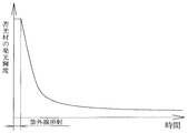
以上の仕組みにより、走行中に車輪が回転することで、ホイールリム(3)上の 全周どこに配置された蓄光機能部位(2)に対しても紫外線が繰り返し照射 される。高輝度発光が持続出来る理由を、蓄光材の発光特性1(図3)および 蓄光材の発光特性2(図4)のグラフにて説明する。通常、一時的に一定時間 のみ紫外線を蓄光材に照射して放置した場合、図3に示す様に、照射している 間は高輝度で発光するが、紫外線照射停止直後から時間の経過とともに発光 輝度が低下し、弱い発光がしばらく持続する。本発明の場合は、図4に示すように 発光輝度が低下する過程で、まだ高い輝度を保っている段階で車輪の回転により 紫外線が再照射されるために繰り返し輝度を回復し、高輝度が保たれるのである。 車輪片側における紫外線発光手段(1)の取り付け数量を増やせば蓄光機能 部位(2)の発光輝度は一定レベルまで増す。また、複数取り付ける場合は、各々 離れた角度に取り付けると、紫外線が、再照射されるまでの時間間隔が短くなり、 効率的に発光輝度を上げることが出来る。尚、図1の実施例では、車輪の左右 両側に本発明を取り付けているが、自転車に取り付け、発電機により発光させる 場合は、発電機の電流供給能力が限られるため左右どちらか片側のみの設置でも 良い。このとき、左側通行を考慮した場合は右側に設置することが望ましい。
【図面の簡単な説明】
【図1】 本発明の断面図(実施例1)
【図2】 本発明の側面図(実施例2)
【図3】 蓄光材の発光特性グラフ1
【図4】 蓄光材の発光特性グラフ2
【図5】 回路図(自転車における実施例)
【符号の説明】
(1)紫外線照明手段
(2)蓄光機能部位
(3)ホイールリム
(4)取り付け手段
(5)タイヤ
(D1,D2,D3,D4)ダイオード
(ZD1)定電圧ダイオード
(R1,R2,R3,R4,R5)固定抵抗器
(C1)コンデンサ
(LED1,LED2,LED3,LED4)紫(紫外線)発光ダイオード
(U1)フォトリレー
(BT)電池
(G)発電機
(B)電球(前照灯)[0001]
The present invention relates to a two-wheeled vehicle wheel light-emitting device that emits ultraviolet light to a phosphorescent functional part provided on a wheel rim of a wheel in a motorcycle by ultraviolet illuminating means so that the luminous part of the wheel rim always emits light with high brightness during night driving. It is about.
[0002]
[Prior art]
Conventionally, as a wheel light emitting means for two-wheeled vehicles to improve nighttime vehicle visibility and fashionability, a reflector is attached to the spoke, a fluorescent sticker is attached to the wheel rim, or a sticker having a phosphorescent function is attached. There was a means of.
[0003]
[Problems to be solved by the invention]
These have the following drawbacks. Reflectors and fluorescent stickers are conspicuous by reflecting light only when exposed to light from the outside, and did not function in places where no external light was applied. Also, seals with a phosphorescent function do not emit light if they are not exposed to light for a certain period of time, and because the time for which sufficient brightness lasts is short, they function effectively when entering a tunnel from a bright place. And so on. The present invention has been made to eliminate these drawbacks.
[0004]
The wheel rim (3) of a motorcycle wheel is provided with a phosphorescent functional part (2), and the ultraviolet illuminating means (1) for irradiating ultraviolet rays toward the wheel rim (3) is adjacent to the wheel rim (3) and does not rotate with the wheel. By providing it, it is possible to repeat the re-irradiation of ultraviolet rays to the luminous function part (2) at any angle of the entire circumference when the wheel rotates, and the luminous function part (2) emits light with high brightness while traveling So that they can continue The present invention is a wheel light emitting device for a motorcycle having the above-described configuration.
[0005]
DETAILED DESCRIPTION OF THE INVENTION
Embodiments of the present invention will be described below. First, a phosphorescent function is added to the wheel rim (3) of the wheel provided in the motorcycle. The wheel may be a front wheel or a rear wheel. The positions to be added are desirably left and right side surfaces that have a large effect of improving visibility. For example, a phosphorescent function seal is applied to the wheel rim (3), or a phosphorescent function paint is applied to the wheel rim (3). The phosphorescent seal and phosphorescent coating itself are not described in the scope of the present invention but are described in detail in the respective inventions, and since they are already commercially available, they are not described here.
[0006]
Next, the ultraviolet illuminating means (1) capable of irradiating ultraviolet rays is attached to the two-wheeled vehicle provided with the luminous function part (2) on the wheel rim (3) of the wheel. The ultraviolet illuminating means (1) referred to in the present invention is an illuminating means for irradiating light containing strong ultraviolet rays, and does not mean that the irradiated light should not contain visible light. For the light source of the ultraviolet illuminating means (1), a purple (ultraviolet) light emitting diode which is strong against impact and has a small current consumption is suitable.
[0007]
The ultraviolet illuminating means (1) is attached to a portion adjacent to the wheel rim (3) and not rotating with the wheel, that is, a fender, a fender fixing stay, a front fork, a suspension fork, a vehicle body frame and the like. The attachment means (4) may be a belt, a metal fitting, a double-sided adhesive tape, or the like, but means that does not easily move the ultraviolet irradiation direction of the ultraviolet irradiation means (1). The irradiation direction of the ultraviolet illuminating means (1) is directed to the luminous function part (2) provided in the wheel rim (3). It is desirable that the distance from the phosphorescent functional part (2) of the ultraviolet illuminating means (1) is a non-contact distance and is attached as close as possible. This is to suppress the diffusion of ultraviolet rays as much as possible to enhance the luminous effect of the phosphorescent functional part (2), and to prevent the rubber of the tire (5) from being deteriorated by the diffused ultraviolet light. It is also for the purpose. The light irradiation direction of the ultraviolet illuminating means (1) is directed to the phosphorescent functional part (2). At least one UV illumination means (1) is attached to one side of the wheel rim (3). By rotating the wheels during traveling, it is possible to irradiate the entire wheel rim (3). For this reason, you may provide the luminous function part (2) provided in a wheel rim (3) in any angle. It may also be provided all around.
[0008]
The power source of the ultraviolet illumination means (1) may be supplied from a power generator provided in the motorcycle or a battery, or a separate power source such as a dry cell may be used exclusively. FIG. 5 shows a circuit diagram of an embodiment of the present invention when a battery is used for a bicycle. The purple (ultraviolet) light emitting diodes (LED1, LED2, LED3, LED4) start to emit light automatically by using the battery (BT) as the power source according to the power generation current of the headlight generator (G). It irradiates a site | part (2). The reason why four purple (ultraviolet) light emitting diodes are provided is to provide one each on the left and right of the front wheel and one on each of the left and right of the rear wheel. A photorelay (U1) is used to detect the generated current. The diodes (D1, D2, D3, D4) are for rectifying the detection current, the fixed resistor (R1) and capacitor (C1) are for voltage smoothing, and the constant voltage diode (ZD1) is for overvoltage protection of the photorelay (U1). is there.
[0009]
With the above mechanism, the wheels rotate while traveling, so that the ultraviolet light is repeatedly irradiated to the phosphorescent functional parts (2) arranged all around the wheel rim (3). The reason why the high-luminance emission can be sustained will be described with reference to the graphs of the luminous characteristics 1 (FIG. 3) of the phosphorescent material and the luminous characteristics 2 (FIG. 4) of the phosphorescent material. Normally, when the phosphorescent material is irradiated temporarily for a certain period of time and left to stand, as shown in Fig. 3, it emits light with high luminance during irradiation, but it emits light with the passage of time immediately after the ultraviolet irradiation is stopped. Luminance decreases and weak light emission lasts for a while. In the case of the present invention, as shown in FIG. 4, in the process of reducing the emission luminance, the ultraviolet rays are re-irradiated by the rotation of the wheel while the high luminance is still maintained. It is kept. Increasing the number of ultraviolet light emitting means (1) attached on one side of the wheel increases the light emission luminance of the phosphorescent functional part (2) to a certain level. In addition, when mounting a plurality of light sources, if they are mounted at different angles, the time interval until the ultraviolet rays are re-irradiated is shortened, and the light emission luminance can be increased efficiently. In the embodiment of FIG. 1, the present invention is attached to both the left and right sides of the wheel. However, when the light is emitted by a generator when attached to a bicycle, the current supply capacity of the generator is limited, so only one of the left and right sides is used. It can be installed. At this time, it is desirable to install on the right side in consideration of left-hand traffic.
[Brief description of the drawings]
FIG. 1 is a sectional view of the present invention (Example 1).
FIG. 2 is a side view of the present invention (Example 2).
[Figure 3] Light emission
[Figure 4]
FIG. 5 is a circuit diagram (example in a bicycle).
[Explanation of symbols]
(1) UV illumination means
(2) Luminous function part
(3) Wheel rim
(4) Attachment means
(5) Tire
(D1, D2, D3, D4) diode
(ZD1) Constant voltage diode
(R1, R2, R3, R4, R5) fixed resistors
(C1) Capacitor
(LED1, LED2, LED3, LED4) Purple (ultraviolet) light emitting diode
(U1) Photorelay
(BT) Battery
(G) Generator
(B) Light bulb (headlight)
Claims (1)
かつ車輪と共に回転しない部位に設けたことを特徴とする二輪車用ホイール 発光装置。In a motorcycle, the wheel rim (3) of the wheel is provided with a phosphorescent functional part (2), and the ultraviolet illumination means (1) is adjacent to the wheel rim (3) so as to irradiate it with ultraviolet light.
A wheel light-emitting device for a motorcycle, which is provided at a portion that does not rotate with the wheel.
Priority Applications (1)
| Application Number | Priority Date | Filing Date | Title |
|---|---|---|---|
| JP2003051992A JP3768964B2 (en) | 2003-01-22 | 2003-01-22 | Wheel light emitting device for motorcycles |
Applications Claiming Priority (1)
| Application Number | Priority Date | Filing Date | Title |
|---|---|---|---|
| JP2003051992A JP3768964B2 (en) | 2003-01-22 | 2003-01-22 | Wheel light emitting device for motorcycles |
Publications (3)
| Publication Number | Publication Date |
|---|---|
| JP2004224323A JP2004224323A (en) | 2004-08-12 |
| JP2004224323A5 JP2004224323A5 (en) | 2005-07-28 |
| JP3768964B2 true JP3768964B2 (en) | 2006-04-19 |
Family
ID=32905722
Family Applications (1)
| Application Number | Title | Priority Date | Filing Date |
|---|---|---|---|
| JP2003051992A Expired - Lifetime JP3768964B2 (en) | 2003-01-22 | 2003-01-22 | Wheel light emitting device for motorcycles |
Country Status (1)
| Country | Link |
|---|---|
| JP (1) | JP3768964B2 (en) |
Cited By (3)
| Publication number | Priority date | Publication date | Assignee | Title |
|---|---|---|---|---|
| KR101379359B1 (en) * | 2013-08-20 | 2014-04-02 | 이종혁 | Side light emitting apparatus for vehicle |
| CN104411573A (en) * | 2012-08-01 | 2015-03-11 | 株式会社技术整合 | Light emitting device and vehicle equipped with light emitting device |
| CN105246772A (en) * | 2012-11-21 | 2016-01-13 | 斯密德西有限公司 | Bicycle light-projecting devices with laser beam |
Families Citing this family (2)
| Publication number | Priority date | Publication date | Assignee | Title |
|---|---|---|---|---|
| JP2009508762A (en) * | 2005-09-21 | 2009-03-05 | ルナシー エルエルシー | Phosphorescent charging system for wheeled vehicles with phosphorescent wheels |
| JP2015120480A (en) * | 2013-12-25 | 2015-07-02 | 信二 細江 | Light irradiation device |
-
2003
- 2003-01-22 JP JP2003051992A patent/JP3768964B2/en not_active Expired - Lifetime
Cited By (4)
| Publication number | Priority date | Publication date | Assignee | Title |
|---|---|---|---|---|
| CN104411573A (en) * | 2012-08-01 | 2015-03-11 | 株式会社技术整合 | Light emitting device and vehicle equipped with light emitting device |
| CN104411573B (en) * | 2012-08-01 | 2018-01-12 | 株式会社技术整合 | Light-emitting device and the vehicle with light-emitting device |
| CN105246772A (en) * | 2012-11-21 | 2016-01-13 | 斯密德西有限公司 | Bicycle light-projecting devices with laser beam |
| KR101379359B1 (en) * | 2013-08-20 | 2014-04-02 | 이종혁 | Side light emitting apparatus for vehicle |
Also Published As
| Publication number | Publication date |
|---|---|
| JP2004224323A (en) | 2004-08-12 |
Similar Documents
| Publication | Publication Date | Title |
|---|---|---|
| US7001051B2 (en) | Human powered vehicle safety lighting structures | |
| US7441914B2 (en) | Phosphorescent charging system for wheeled vehicles having phosphorescent wheels | |
| JP2007238063A (en) | Fluorescent mark for tire | |
| US20060232988A1 (en) | Emitting light device for bicycles | |
| JP3768964B2 (en) | Wheel light emitting device for motorcycles | |
| WO2009144629A1 (en) | Lighting assembly | |
| JP2004224323A5 (en) | ||
| KR200418311Y1 (en) | Luminous eyeline for headlight | |
| KR101379359B1 (en) | Side light emitting apparatus for vehicle | |
| CN103448841A (en) | Novel safe-riding bicycle | |
| JP2009508762A (en) | Phosphorescent charging system for wheeled vehicles with phosphorescent wheels | |
| JP2004276887A (en) | Lighting system for tire having luminous function | |
| KR20080004707U (en) | Radiation apparatus of generating type for mounting hub of a body of revolution | |
| JP2015120480A (en) | Light irradiation device | |
| JP3185528U (en) | Light irradiation device | |
| JP3112620U (en) | A light emitting label using an EL (electroluminescence) element light emitting base as a light source. | |
| CN203832629U (en) | Bicycle capable of improving safety in running process | |
| JP3203408U (en) | Bicycle display system | |
| JP2007276756A (en) | Stroboscopic image and character display unit for tire | |
| JP2002029471A (en) | El(electro-luminescence) sticker device for bicycle | |
| KR100512754B1 (en) | bicycle founded safty radiation apparatus to work by independent power | |
| KR20230040456A (en) | LED Bike | |
| JP3193492U (en) | Bicycle indicator | |
| JPH1178674A (en) | Lamp for bicycle | |
| JP2000076592A (en) | Internal illumination type display device |
Legal Events
| Date | Code | Title | Description |
|---|---|---|---|
| A521 | Request for written amendment filed |
Free format text: JAPANESE INTERMEDIATE CODE: A523 Effective date: 20040426 |
|
| A521 | Request for written amendment filed |
Free format text: JAPANESE INTERMEDIATE CODE: A523 Effective date: 20041220 |
|
| A621 | Written request for application examination |
Free format text: JAPANESE INTERMEDIATE CODE: A621 Effective date: 20041220 |
|
| A871 | Explanation of circumstances concerning accelerated examination |
Free format text: JAPANESE INTERMEDIATE CODE: A871 Effective date: 20050413 |
|
| A131 | Notification of reasons for refusal |
Free format text: JAPANESE INTERMEDIATE CODE: A131 Effective date: 20050712 |
|
| A521 | Request for written amendment filed |
Free format text: JAPANESE INTERMEDIATE CODE: A523 Effective date: 20050722 |
|
| A521 | Request for written amendment filed |
Free format text: JAPANESE INTERMEDIATE CODE: A821 Effective date: 20050704 |
|
| A975 | Report on accelerated examination |
Free format text: JAPANESE INTERMEDIATE CODE: A971005 Effective date: 20050826 |
|
| A131 | Notification of reasons for refusal |
Free format text: JAPANESE INTERMEDIATE CODE: A131 Effective date: 20050906 |
|
| TRDD | Decision of grant or rejection written | ||
| A01 | Written decision to grant a patent or to grant a registration (utility model) |
Free format text: JAPANESE INTERMEDIATE CODE: A01 Effective date: 20060117 |
|
| R150 | Certificate of patent or registration of utility model |
Ref document number: 3768964 Country of ref document: JP Free format text: JAPANESE INTERMEDIATE CODE: R150 Free format text: JAPANESE INTERMEDIATE CODE: R150 |
|
| FPAY | Renewal fee payment (event date is renewal date of database) |
Free format text: PAYMENT UNTIL: 20120210 Year of fee payment: 6 |
|
| R250 | Receipt of annual fees |
Free format text: JAPANESE INTERMEDIATE CODE: R250 |
|
| FPAY | Renewal fee payment (event date is renewal date of database) |
Free format text: PAYMENT UNTIL: 20120210 Year of fee payment: 6 |
|
| FPAY | Renewal fee payment (event date is renewal date of database) |
Free format text: PAYMENT UNTIL: 20150210 Year of fee payment: 9 |
|
| R250 | Receipt of annual fees |
Free format text: JAPANESE INTERMEDIATE CODE: R250 |
|
| FPAY | Renewal fee payment (event date is renewal date of database) |
Free format text: PAYMENT UNTIL: 20150210 Year of fee payment: 9 |
|
| S201 | Request for registration of exclusive licence |
Free format text: JAPANESE INTERMEDIATE CODE: R314201 |
|
| FPAY | Renewal fee payment (event date is renewal date of database) |
Free format text: PAYMENT UNTIL: 20150210 Year of fee payment: 9 |
|
| R360 | Written notification for declining of transfer of rights |
Free format text: JAPANESE INTERMEDIATE CODE: R360 |
|
| FPAY | Renewal fee payment (event date is renewal date of database) |
Free format text: PAYMENT UNTIL: 20150210 Year of fee payment: 9 |
|
| R370 | Written measure of declining of transfer procedure |
Free format text: JAPANESE INTERMEDIATE CODE: R370 |
|
| S201 | Request for registration of exclusive licence |
Free format text: JAPANESE INTERMEDIATE CODE: R314201 |
|
| FPAY | Renewal fee payment (event date is renewal date of database) |
Free format text: PAYMENT UNTIL: 20150210 Year of fee payment: 9 |
|
| R350 | Written notification of registration of transfer |
Free format text: JAPANESE INTERMEDIATE CODE: R350 |
|
| FPAY | Renewal fee payment (event date is renewal date of database) |
Free format text: PAYMENT UNTIL: 20150210 Year of fee payment: 9 |
|
| FPAY | Renewal fee payment (event date is renewal date of database) |
Free format text: PAYMENT UNTIL: 20160210 Year of fee payment: 10 |
|
| R250 | Receipt of annual fees |
Free format text: JAPANESE INTERMEDIATE CODE: R250 |
|
| R250 | Receipt of annual fees |
Free format text: JAPANESE INTERMEDIATE CODE: R250 |
|
| R250 | Receipt of annual fees |
Free format text: JAPANESE INTERMEDIATE CODE: R250 |
|
| R250 | Receipt of annual fees |
Free format text: JAPANESE INTERMEDIATE CODE: R250 |
|
| R250 | Receipt of annual fees |
Free format text: JAPANESE INTERMEDIATE CODE: R250 |
|
| R250 | Receipt of annual fees |
Free format text: JAPANESE INTERMEDIATE CODE: R250 |
|
| R250 | Receipt of annual fees |
Free format text: JAPANESE INTERMEDIATE CODE: R250 |
|
| EXPY | Cancellation because of completion of term |