JP3768161B2 - Nozzle assembly for introducing pressurized fluid and injection molding method - Google Patents
Nozzle assembly for introducing pressurized fluid and injection molding method Download PDFInfo
- Publication number
- JP3768161B2 JP3768161B2 JP2002017614A JP2002017614A JP3768161B2 JP 3768161 B2 JP3768161 B2 JP 3768161B2 JP 2002017614 A JP2002017614 A JP 2002017614A JP 2002017614 A JP2002017614 A JP 2002017614A JP 3768161 B2 JP3768161 B2 JP 3768161B2
- Authority
- JP
- Japan
- Prior art keywords
- outer cylinder
- pressurized fluid
- hole
- center pin
- mounting base
- Prior art date
- Legal status (The legal status is an assumption and is not a legal conclusion. Google has not performed a legal analysis and makes no representation as to the accuracy of the status listed.)
- Expired - Fee Related
Links
Images


Classifications
-
- B—PERFORMING OPERATIONS; TRANSPORTING
- B29—WORKING OF PLASTICS; WORKING OF SUBSTANCES IN A PLASTIC STATE IN GENERAL
- B29C—SHAPING OR JOINING OF PLASTICS; SHAPING OF MATERIAL IN A PLASTIC STATE, NOT OTHERWISE PROVIDED FOR; AFTER-TREATMENT OF THE SHAPED PRODUCTS, e.g. REPAIRING
- B29C45/00—Injection moulding, i.e. forcing the required volume of moulding material through a nozzle into a closed mould; Apparatus therefor
- B29C45/17—Component parts, details or accessories; Auxiliary operations
- B29C45/1703—Introducing an auxiliary fluid into the mould
- B29C45/1734—Nozzles therefor
Description
【0001】
【発明の属する技術分野】
本発明は、例えば、金型に設けられたキャビティ内に射出された溶融樹脂の内部に加圧流体を導入するための加圧流体導入用ノズル組立体、及び、係る加圧流体導入用ノズル組立体が組み込まれた金型組立体を用いた射出成形方法に関する。
【0002】
【従来の技術】
金型に設けられたキャビティ内に射出された溶融樹脂の内部に加圧流体を導入するための加圧流体導入用ノズル組立体が、例えば、特開昭64−14012号公報や特開平5−293853号公報に提案されている。
【0003】
特開昭64−14012号公報に開示された加圧流体導入用ノズル組立体においては、その第2図に示されているように、弁構成の中心口の出口端に逆止弁が備えられている。即ち、ノズル26の下流端には、ねじ切りキャップ32によって閉じ込められたボール31から成る逆止弁30が配設されている。そして、逆止弁30によって、キャビティ内に射出された溶融樹脂、及び、溶融樹脂内部に導入された加圧流体が弁構成の中心口を通って逆流することを防止している。
【0004】
また、特開平5−293853号公報には、インモールドガスの圧力によってガス噴出口を樹脂逆流防止板に圧接させることでキャビティにおいて成形品を多数個成形するためのインモールドガス注入ノズルが提案されている。このインモールドガス注入ノズルにあっては、その図3に示された従来のインモールドガス注入ノズルにおける油圧シリンダーの駆動源が不要となる。
【0005】
特開平5−293853号公報に開示されたインモールドガス注入ノズルは、その図1に示されているように、摺動孔(13a)を一端側に設けるとともに他端側に加圧室(13b)を設けてガス注入口(13d)を有するシリンダ本体(13)と、先端にガス噴出口(14a)を設けて他端側にフランジ部(14b)を有し中心にガス流路(14c)を設けて、上記摺動孔(13a)と該加圧室(13b)を摺動するフランジ部(14b)を配したニードル(14)と、上記シリンダ本体(13)の該加圧室(13b)を密閉する圧入部(15a)を設けたストッパ(15)と、上記ニードル(14)を復旧方向に付勢する弾性部材(16)とからなり、上記シリンダ本体(13)の該加圧室(13b)を上記ストッパ(15)の該圧入部(15a)で密閉して、当該加圧室(13b)に注入するガス圧によりニードル(14)を駆動してインモールドガスが注入できるように構成されている。そして、実施例での説明によると、ニードル14のガス噴出口14aが図示していない金型に配設された樹脂逆流防止板2へ圧接するようにシリンダ本体13を固定して、シリンダ本体13の加圧室13bに加圧されたインモールドガスを供給してニードル14の先端を樹脂逆流防止板2へ圧接させ、そのガス噴出口14aからインモールドガスを噴出すると共に、キャビティ内にモールド用の合成樹脂を射出して樹脂モールドに中空部を形成し、その後、前記加圧室13bよりインモールドガスを排出することでニードル14が復旧してガス流路14cをストッパ15のバルブ部15cで閉鎖している。
【0006】
【発明が解決しようとする課題】
ところで、特開昭64−14012号公報に開示された加圧流体導入用ノズル組立体においては、ノズル26とねじ切りキャップ32のねじ部分の組み立て状態によっては、加圧流体がノズル26とねじ切りキャップ32との間から漏れ出し、キャビティ内に射出された溶融樹脂の内部に加圧流体を導入できない場合がある。また、ノズル本体、ねじ切りキャップ32、ボール31から加圧流体導入用ノズル組立体が構成されているが故に、加圧流体導入用ノズル組立体の小型化が困難である。更には、溶融樹脂の射出時、キャビティ内に射出された溶融樹脂が、中心口28の先端を経由して、ボール31に到達することがある。この中心口28に流入した溶融樹脂は、冷却し始め、加圧流体をキャビティ内の溶融樹脂の内部に導入する際に固化が進み、加圧流体をキャビティ内の溶融樹脂の内部に導入することが困難となる場合がある。
【0007】
また、特開平5−293853号公報に開示されたインモールドガス注入ノズルにあっては、溶融樹脂のキャビティへの射出前にガス噴出口14aを樹脂逆流防止板2へ圧接させるために、インモールドガス注入ノズルにインモールドガスを供給する。従って、供給されたインモールドガスはガス噴出口14aから噴出してしまう。この状態でキャビティ内に溶融樹脂を射出すると、射出された溶融樹脂がガス噴出口14aに到達したとき、以下の問題が生じる。即ち、
(1)ガス噴出口14aで溶融樹脂とインモールドガスが混合される結果、美麗な成形品を得ることができない。
(2)射出された溶融樹脂の圧力が噴出しているインモールドガスの圧力よりも高い場合、ニードルのガス噴出口14aから溶融樹脂がガス流路14cに逆流し、固化してしまい、インモールドガス注入ノズルを閉塞する結果、インモールドガスの溶融樹脂内部への導入を阻害する場合がある。
(3)溶融樹脂の射出に先立ってインモールドガスが噴出するため、インモールドガスの消費量が著しく大きくなる可能性がある。
【0008】
特開平5−293853号公報に開示されたインモールドガス注入ノズルにあっては、更には、下記の問題点が存在する。即ち、
(4)シリンダ本体13にストッパ15が圧入されているので、ストッパ15の交換をすることができないし、シリンダ本体13とストッパ15との間からインモールドガスが漏れる虞がある。
(5)ニードル14のフランジ部14bは、シリンダ本体13内で摺動する構成となっており、加圧室13bに圧入されたインモールドガスがフランジ部14bの外側を通過し、ニードル14の外周を通ってインモールドガス注入ノズルの外側に漏れ出した場合、キャビティ内に射出された樹脂の内部に形成された中空部に十分な加圧を加えることができないばかりか、中空部の形成すらもできない場合がある。
(6)図1及び図2に示されているように、ガス注入口13dがシリンダ本体13の側壁に設けられているが故に、インモールドガスのための配管をシリンダ本体13と直角方向に取り付けなければならず、配管スペースを必要とし、配管を含むインモールドガス注入ノズルの金型への取付スペースが大きくなる。
【0009】
従って、本発明の目的は、金型に設けられたキャビティ内に射出された溶融樹脂の内部に加圧流体を確実に導入することができ、金型への取付スペースが大きくならない加圧流体導入用ノズル組立体、及び、係る加圧流体導入用ノズル組立体が組み込まれた金型組立体を用いた射出成形方法を提供することにある。
【0010】
【課題を解決するための手段】
上記の目的を達成するための本発明の加圧流体導入用ノズル組立体は、
(A)貫通孔を有し、後部に突起部が設けられた外筒、
(B)外筒に設けられた該貫通孔内に格納され、外筒から後部が突出し、該後部に拡径部が設けられたセンターピン、
(C)先端部に貫通孔を有し、更に、該貫通孔から延在する拡径領域を内部に有し、該貫通孔に外筒が通され、外筒の突起部をセンターピンの軸線方向に沿って移動可能に該拡径領域に収納する外筒ホルダー、
(D)外筒ホルダーの拡径領域内に収納され、外筒の突起部をセンターピンの後部方向に向かって付勢するバネ部材、
(E)外筒ホルダーの後端部に取り付けられ、前部には加圧流体流路貫通孔及びセンターピンを通す貫通孔が設けられ、内部にはセンターピンの拡径部を収納する孔部が設けられた外筒ホルダー用取付ベース、
(F)外筒ホルダー用取付ベースの後端部に取り付けられ、加圧流体流路貫通孔が設けられたコネクター、並びに、
(G)外筒ホルダー用取付ベースの前面凹部と外筒の後部側面との間に配置された摺動パッキング、
から成り、
金型に設けられたキャビティ内に射出された溶融樹脂の内部に加圧流体を導入するための加圧流体導入用ノズル組立体であって、
コネクターに設けられた加圧流体流路貫通孔は、外筒ホルダー用取付ベースに設けられた孔部とセンターピンに設けられた拡径部との間の隙間、及び、外筒ホルダー用取付ベースに設けられた加圧流体流路貫通孔を介して、外筒に設けられた貫通孔とセンターピンとの間に形成された隙間に連通しており、
外筒は、センターピン、外筒ホルダー及び外筒ホルダー用取付ベースに対して、センターピンの軸線方向に沿って前後に摺動可能であり、
溶融樹脂の内部に加圧流体を導入しないときには、外筒に設けられた突起部はバネ部材によってセンターピンの後部方向に向かって付勢された状態にあり、且つ、外筒の貫通孔先端部はセンターピンによって閉塞されており、
溶融樹脂の内部に加圧流体を導入しているとき、コネクターに設けられた加圧流体流路貫通孔から導入された加圧流体は、外筒ホルダー用取付ベースに設けられた孔部とセンターピンに設けられた拡径部との間の隙間、及び、外筒ホルダー用取付ベースに設けられた加圧流体流路貫通孔を介して、外筒に設けられた貫通孔とセンターピンとの間に形成された隙間に侵入し、且つ、バネ部材の付勢力に打ち勝って外筒を前進端へと移動させ、以て、外筒の貫通孔先端部を解放状態とすることを特徴とする。
【0011】
上記の目的を達成するための本発明の射出成形方法は、
(A)貫通孔を有し、後部に突起部が設けられた外筒、
(B)外筒に設けられた該貫通孔内に格納され、外筒から後部が突出し、該後部に拡径部が設けられたセンターピン、
(C)先端部に貫通孔を有し、更に、該貫通孔から延在する拡径領域を内部に有し、該貫通孔に外筒が通され、外筒の突起部をセンターピンの軸線方向に沿って移動可能に該拡径領域に収納する外筒ホルダー、
(D)外筒ホルダーの拡径領域内に収納され、外筒の突起部をセンターピンの後部方向に向かって付勢するバネ部材、
(E)外筒ホルダーの後端部に取り付けられ、前部には加圧流体流路貫通孔及びセンターピンを通す貫通孔が設けられ、内部にはセンターピンの拡径部を収納する孔部が設けられた外筒ホルダー用取付ベース、
(F)外筒ホルダー用取付ベースの後端部に取り付けられ、加圧流体流路貫通孔が設けられたコネクター、並びに、
(G)外筒ホルダー用取付ベースの前面凹部と外筒の後部側面との間に配置された摺動パッキング、
から成り、
金型に設けられたキャビティ内に射出された溶融樹脂の内部に加圧流体を導入するための加圧流体導入用ノズル組立体であって、
コネクターに設けられた加圧流体流路貫通孔は、外筒ホルダー用取付ベースに設けられた孔部とセンターピンに設けられた拡径部との間の隙間、及び、外筒ホルダー用取付ベースに設けられた加圧流体流路貫通孔を介して、外筒に設けられた貫通孔とセンターピンとの間に形成された隙間に連通しており、
外筒は、センターピン、外筒ホルダー及び外筒ホルダー用取付ベースに対して、センターピンの軸線方向に沿って前後に摺動可能である加圧流体導入用ノズル組立体が、キャビティを有する金型に取り付けられた金型組立体を用いた射出成形方法であって、
(a)キャビティ内に溶融樹脂を射出する前には、外筒に設けられた突起部をバネ部材によってセンターピンの後部方向に向かって付勢された状態とし、且つ、外筒の貫通孔先端部をセンターピンによって閉塞された状態とし、
(b)キャビティ内に溶融樹脂を射出中若しくは射出完了と同時若しくは射出完了後、コネクターに設けられた加圧流体流路貫通孔から加圧流体を導入し、該導入された加圧流体を、外筒ホルダー用取付ベースに設けられた孔部とセンターピンに設けられた拡径部との間の隙間、及び、外筒ホルダー用取付ベースに設けられた加圧流体流路貫通孔を介して、外筒に設けられた貫通孔とセンターピンとの間に形成された隙間に侵入させ、且つ、該導入された加圧流体によってバネ部材の付勢力に打ち勝って外筒を前進端へと移動させ、以て、外筒の貫通孔先端部を解放状態とし、キャビティ内に射出された溶融樹脂の内部に加圧流体を導入し、該溶融樹脂の内部に中空部を形成し、その後、キャビティ内の樹脂を冷却、固化させることを特徴とする。
【0012】
本発明の加圧流体導入用ノズル組立体あるいは射出成形方法(以下、これらを総称して、単に、本発明と呼ぶ)において、溶融樹脂の内部に加圧流体を導入しないときには、あるいは又、キャビティ内に溶融樹脂を射出する前には、外筒に設けられた突起部の外縁部分と外筒ホルダー用取付ベースに設けられた前面外縁部分とは、バネ部材によって接触状態にある構成とすることが好ましい。
【0013】
本発明にあっては、外筒の前部外径(D1)を、1.5mm乃至5mm、好ましくは2.0mm乃至3.5mmとすることが、外筒作製工程における加工性及び金型との組立性といった観点から好ましい。ここで、外筒の前部外径(D1)とは、外筒の突起部が設けられた部分以外の部分の外径を指す。また、外筒に設けられた貫通孔の直径(D2)を、0.6mm乃至3.1mm、好ましくは1.0mm乃至2.5mmとすることが望ましい。更には、センターピンの前部直径(D3)を、0.5mm乃至3mm、好ましくは0.9mm乃至2.4mmとすることが、センターピン作製工程における加工性及び加圧流体導入用ノズル組立体の組立性といった観点から望ましい。ここで、センターピンの前部直径(D3)とは、センターピンの拡径部が設けられた部分以外の部分の直径を指す。D2とD3の関係、即ち、外筒に設けられた貫通孔とセンターピンとの間に形成された隙間[SP1=(D2−D3)/2]の平均値は、0.05mm≦SP1≦1.3mm、好ましくは0.1mm≦SP1≦1.0mmを満足することが、例えばキャビティ内に射出された溶融樹脂の内部に加圧流体を確実に導入するといった観点から望ましい。また、外筒の貫通孔先端部がセンターピンによって閉塞されている状態における外筒の貫通孔先端部とこの先端部に対向したセンターピンの部分との間の隙間SP2の平均値は、0.002mm≦SP2≦0.04mm、好ましくは0.005mm≦SP2≦0.02mmを満足することが、この隙間から溶融樹脂が浸入し、外筒に設けられた貫通孔とセンターピンとの間に形成された隙間が閉塞されることを防止するといった観点から望ましい。
【0014】
本発明において、外筒の摺動距離(L)は、0.1mm乃至1mm、好ましくは0.2mm乃至0.7mmであることが、加圧流体導入用ノズル組立体の組立調整の容易性及び機能の信頼性といった観点から望ましい。
【0015】
本発明においては、加圧流体導入用ノズル組立体を前後に移動させる移動装置に加圧流体導入用ノズル組立体が取り付けられていることが望ましい。ここで、移動装置として、油圧シリンダー、空気圧シリンダー、電動モータを例示することができる。
【0016】
本発明において、外筒の最先端面は、溶融樹脂の内部に加圧流体を導入しないときには、キャビティを構成する金型面と同じ面内にあり、溶融樹脂の内部に加圧流体を導入しているときには、キャビティを構成する金型面よりも突出している構成としてもよいし、溶融樹脂の内部に加圧流体を導入しないとき、及び、溶融樹脂の内部に加圧流体を導入しているとき、キャビティを構成する金型面よりも突出している構成としてもよいし、溶融樹脂の内部に加圧流体を導入しないときには、キャビティを構成する金型面よりも引っ込んだ位置にあり、溶融樹脂の内部に加圧流体を導入しているときには、キャビティを構成する金型面と同じ面内にあり、あるいは又、キャビティを構成する金型面よりも突出している構成としてもよい。更には、溶融樹脂の内部に加圧流体を導入しないとき、及び、溶融樹脂の内部に加圧流体を導入しているとき、キャビティを構成する金型面よりも引っ込んだ位置にある構成としてもよい。この場合、溶融樹脂の射出時、溶融樹脂はキャビティを構成する金型面の外側に配分される。また、加圧流体導入用ノズル組立体を金型のスプルーやランナー内に配置してもよい。ここで、「キャビティを構成する金型面よりも突出している」とは、外筒の最先端面がキャビティ内に位置することを意味し、「キャビティを構成する金型面よりも引っ込んだ位置にある」とは、外筒の最先端面がキャビティ内には位置せず、且つ、キャビティを構成する金型面と同じ面内にも位置しないことを意味する。
【0017】
また、本発明においては、バネ部材をコイルバネから構成し、あるいは又、皿バネから構成することが好ましい。バネ部材をコイルバネから構成する場合、押しバネ型としてよいし、引きバネ型としてもよい。
【0018】
外筒、センターピン、外筒ホルダー、外筒ホルダー用取付ベース、コネクターを構成する材料は、例えば、金型の作製に一般に使用されている鋼材から適宜選択すればよい。耐食性が要求される場合には、ステンレス鋼等を選択すればよい。摺動パッキングは、気体用パッキングであって摺動性の優れたパッキングから適宜選択すればよく、例えば、テトラフルオロエチレン等の樹脂がコーティングされたパッキングを用いることが好ましい。
【0019】
本発明の射出成形方法での使用に適した樹脂として、結晶性熱可塑性樹脂や非晶性熱可塑性樹脂を挙げることができ、具体的には、ポリエチレン樹脂、ポリプロピレン樹脂等のポリオレフィン系樹脂;ポリアミド6、ポリアミド66、ポリアミドMXD6等のポリアミド系樹脂;ポリオキシメチレン(ポリアセタール,POM)樹脂;ポリエチレンテレフタレート(PET)樹脂、ポリブチレンテレフタレート(PBT)樹脂等のポリエステル系樹脂;ポリフェニレンサルファイド樹脂;ポリスチレン樹脂、AS樹脂、ABS樹脂、AES樹脂等のスチレン系樹脂;PMMA樹脂等のメタクリル系樹脂;ポリカーボネート樹脂;変性PPE樹脂;ポリスルホン樹脂;ポリエーテルスルホン樹脂;ポリアリレート樹脂;ポリエーテルイミド樹脂;ポリアミドイミド樹脂;ポリイミド系樹脂;ポリエーテルケトン樹脂;ポリエーテルエーテルケトン樹脂;変性ポリフェニレンエーテル(PPE)樹脂;ポリエステルカーボネート樹脂;液晶ポリマーを例示することができる。
【0020】
更には、本発明の射出成形方法においては、ポリマーアロイ材料から成る熱可塑性樹脂を用いることができる。ここで、ポリマーアロイ材料は、少なくとも2種類の熱可塑性樹脂をブレンドしたもの、又は、少なくとも2種類の熱可塑性樹脂を化学的に結合させたブロック共重合体若しくはグラフト共重合体から成る。ポリマーアロイ材料は、単独の熱可塑性樹脂のそれぞれが有する特有な性能を合わせ持つことができる高機能材料として広く使用されている。少なくとも2種類の熱可塑性樹脂をブレンドしたポリマーアロイ材料を構成する熱可塑性樹脂として、ポリスチレン樹脂、ABS樹脂、AES樹脂、AS樹脂といったスチレン系樹脂;ポリエチレン樹脂、ポリプロピレン樹脂等のポリオレフィン系樹脂;メタクリル樹脂;ポリカーボネート樹脂;ポリアミド6、ポリアミド66、ポリアミドMXD6等のポリアミド系樹脂;変性PPE樹脂;ポリブチレンテレフタレート樹脂やポリエチレンテレフタレート樹脂等のポリエステル樹脂;ポリオキシメチレン樹脂;ポリスルホン樹脂;ポリイミド樹脂;ポリフェニレンサルファイド樹脂;ポリアリレート樹脂;ポリエーテルスルホン樹脂;ポリエーテルケトン樹脂;ポリエーテルエーテルケトン樹脂;ポリエステルカーボネート樹脂を挙げることができる。2種類の熱可塑性樹脂をブレンドしたポリマーアロイ材料として、ポリカーボネート樹脂とABS樹脂とのポリマーアロイ材料を例示することができる。尚、このような樹脂の組合せを、ポリカーボネート樹脂/ABS樹脂と表記する。以下においても同様である。更に、少なくとも2種類の熱可塑性樹脂をブレンドしたポリマーアロイ材料として、ポリカーボネート樹脂/PET樹脂、ポリカーボネート樹脂/PBT樹脂、ポリカーボネート樹脂/ポリアミド系樹脂、ポリカーボネート樹脂/PBT樹脂/PET樹脂、変性PPE樹脂/HIPS樹脂、変性PPE樹脂/ポリアミド系樹脂、変性PPE樹脂/PBT樹脂/PET樹脂、変性PPE樹脂/ポリアミドMXD6樹脂、ポリオキシメチレン樹脂/ポリウレタン樹脂、PBT樹脂/PET樹脂を例示することができる。
【0021】
尚、以上に説明した各種の熱可塑性樹脂に、安定剤、紫外線吸収剤、離型剤、染顔料等を添加することができるし、ガラスビーズ、マイカ、カオリン、炭酸カルシウム等の無機充填材、あるいは有機充填材を添加することもできる。
【0022】
本発明の射出成形方法においては、繊維状の充填材、より具体的には、無機繊維を5重量%乃至50重量%含有する熱可塑性樹脂を用いることもできる。射出成形品の強度を重視する場合には、無機繊維の平均長さを、5μm乃至5mm、好ましくは10μm乃至0.4mmとし、射出成形品の平滑性を重視する場合には、5μm乃至0.4mm、より好ましくは5μm乃至0.2mm、一層好ましくは5μm乃至0.1mmとすることが望ましい。また、これらの場合、無機繊維の平均直径を、0.01μm乃至15μm、より好ましくは0.1μm乃至13μm、一層好ましくは0.1μm乃至10μmとすることが望ましい。
【0023】
無機繊維は、ガラス繊維、カーボン繊維、ウォラストナイト、ホウ酸アルミニウムウィスカー繊維、チタン酸カリウムウィスカー繊維、塩基性硫酸マグネシウムウィスカー繊維、珪酸カルシウムウィスカー繊維及び硫酸カルシウムウィスカー繊維から成る群から選択された少なくとも1種の材料から構成することが好ましい。尚、熱可塑性樹脂に含有される無機繊維は1種類に限定されず、2種類以上の無機繊維を熱可塑性樹脂に含有させてもよい。
【0024】
無機繊維の平均長さは、重量平均長さを意味する。無機繊維の長さの測定は、熱可塑性樹脂の樹脂成分を溶解する液体に無機繊維を含有する成形用ペレット若しくは成形品を浸漬して樹脂成分を溶解するか、ガラス繊維の場合、600゜C以上の高温で樹脂成分を燃焼させて、残留する無機繊維を顕微鏡等で観察して測定することができる。通常、無機繊維を写真撮影して人が測長するか、専用の繊維長測定装置を使用して無機繊維の長さを求める。数平均長さでは微小に破壊された繊維の影響が大き過ぎるので、重量平均長さを採用することが好ましい。重量平均長さの測定に際しては、あまりに小さく破砕された無機繊維の破片を除いて測定する。無機繊維の公称直径の2倍よりも長さが短くなると測定が難しくなるので、例えば公称直径の2倍以上の長さを有する無機繊維を測定の対象とする。
【0025】
本発明において、導入する加圧流体として、窒素ガス、炭酸ガス、空気、ヘリウムガス等常温でガス状の物質を使用することができるし、水等の液体や高圧下で液化したガスも使用可能である。
【0026】
成形品の成形にあたって、射出成形時の溶融樹脂の量、温度、圧力あるいは射出速度、導入すべき加圧流体の量、圧力あるいは速度、金型の冷却時間等、種々の条件は、使用する樹脂の種類、金型の形状等に依存して、適宜選択、制御する必要があり、一義的に定めることはできない。
【0027】
本発明の加圧流体導入用ノズル組立体は、射出圧縮成形方法を含む射出成形方法において用いることができるだけでなく、ブロー成形方法においても用いることができる。
【0028】
本発明においては、加圧流体導入用ノズル組立体に圧入箇所が存在しないので組立等を容易に行うことができるし、加圧流体の導入部分であるコネクターに設けられた加圧流体流路貫通孔がセンターピンの軸線方向と一致しているので金型への取付スペースを小さくすることができる。
【0029】
【実施例】
以下、図面を参照して、実施例に基づき本発明を説明するが、本発明は以下の実施例に限定されるものではない。
【0030】
(実施例1)
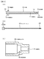
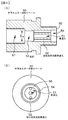
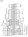
実施例1の加圧流体導入用ノズル組立体の模式的な断面図を図1に示す。また、外筒及びセンターピンの先端部分を拡大した模式的な断面図を図2の(A)及び(B)に示し、図2の(A)の矢印C−C及び矢印D−Dに沿った模式的な断面図を図2の(C)、図2の(D)に示す。更には、加圧流体導入用ノズル組立体から外筒、センターピン及び外筒ホルダーを取り出したときの、外筒、センターピン及び外筒ホルダーのそれぞれの模式的な断面図を図3の(A)、(B)、(C)に示す。また、加圧流体導入用ノズル組立体から外筒ホルダー用取付ベースを取り出したときの、外筒ホルダー用取付ベースの模式的な断面図及び側面図を図4の(A)、(B)に示す。更には、加圧流体導入用ノズル組立体のバネ部材の周囲の拡大された模式的な一部断面図を図5及び図7に示し、センターピンの拡径部の周囲の拡大された模式的な一部断面図を図6に示す。
【0031】
金型に設けられたキャビティ内に射出された溶融樹脂の内部に加圧流体を導入するための実施例1の加圧流体導入用ノズル組立体は、外筒10と、センターピン20と、外筒ホルダー30と、バネ部材40と、外筒ホルダー用取付ベース50と、コネクター60と、摺動パッキング41から構成されている。
【0032】
外筒10は、貫通孔11を有し、後部に突起部12が設けられている。
【0033】
また、センターピン20は、外筒10に設けられた貫通孔11内に格納され、外筒10から後部が突出し、この後部には拡径部21が設けられている。
【0034】
外筒ホルダー30は、先端部に貫通孔31を有し、更に、この貫通孔31から延在する拡径領域32を内部に有し、この貫通孔31に外筒10が通されている。外筒10の突起部12は、センターピン20の軸線方向に沿って移動可能に拡径領域32に収納されている。
【0035】
押しバネ型のコイルバネから成るバネ部材40は、外筒ホルダー30の拡径領域32内に収納され、外筒10の突起部12をセンターピン20の後部方向に向かって付勢している。
【0036】
外筒ホルダー用取付ベース50は、外筒ホルダー30の後端部に螺合した状態で取り付けられている。そして、前部の中央部にはセンターピン20を通す貫通孔51が設けられ、前部の外縁側には2つの加圧流体流路貫通孔52が設けられ、内部にはセンターピン20の拡径部21を収納する孔部53が設けられている。加圧流体流路貫通孔52は孔部53に開口している。ここで、バネ部材40の付勢力によって、外筒ホルダー用取付ベース50の前面外縁部分55と外筒10に設けられた突起部12の外縁部分13とが接触する。
【0037】
コネクター60は、外筒ホルダー用取付ベースの後端部(コネクター取付部57)に螺合した状態で取り付けられており、中心部には加圧流体流路貫通孔61が設けられている。加圧流体流路貫通孔61は、配管を介して加圧流体源に接続されている。尚、配管及び加圧流体源の図示は省略した。
【0038】
コネクター60に設けられた加圧流体流路貫通孔61は、外筒ホルダー用取付ベース50に設けられた孔部53とセンターピン20に設けられた拡径部21との間の隙間56、及び、外筒ホルダー用取付ベース50に設けられた加圧流体流路貫通孔52を介して、外筒10に設けられた貫通孔11とセンターピン20との間に形成された隙間23に連通している。また、外筒10は、センターピン20、外筒ホルダー30及び外筒ホルダー用取付ベース50に対して、センターピン20の軸線方向に沿って前後に摺動可能である。
【0039】
摺動パッキング41は、外筒ホルダー用取付ベース50の前面凹部54と外筒10の後部側面14との間に配置されている。摺動パッキング41によって外筒ホルダー用取付ベース50の内部の気密性を保持することができ、外筒ホルダー用取付ベース50から外筒ホルダー30の拡径領域32への加圧流体の漏洩を防止することができるし、コネクター60に設けられた加圧流体流路貫通孔61から導入された加圧流体を、外筒ホルダー用取付ベース50の内部を通じて確実に外筒10に設けられた貫通孔11とセンターピン20との間に形成された隙間23に導入することができる。
【0040】
図2の(A)及び図5に示すように、例えば、溶融樹脂の内部に加圧流体を導入しないときには、外筒10に設けられた突起部12の外縁部分13と外筒ホルダー用取付ベース50に設けられた前面外縁部分55とはバネ部材40の付勢力によって接触状態にあり、且つ、外筒10の貫通孔先端部15はセンターピン20によって閉塞されている。これによって、例えばキャビティ内に射出された溶融樹脂が、外筒10に設けられた貫通孔11とセンターピン20との間に形成された隙間23に流入することを確実に防止することができる。
【0041】
一方、図2の(B)及び図7に示すように、例えば、溶融樹脂の内部に加圧流体を導入しているとき、コネクター60に設けられた加圧流体流路貫通孔61から導入された加圧流体は、外筒ホルダー用取付ベース50に設けられた孔部53とセンターピン20に設けられた拡径部21との間の隙間56、及び、外筒ホルダー用取付ベース50に設けられた加圧流体流路貫通孔52を介して、外筒10に設けられた貫通孔11とセンターピン20との間に形成された隙間23に侵入し、且つ、バネ部材40の付勢力に打ち勝って外筒10を前進端へと移動させ、以て、外筒10の貫通孔先端部15は解放状態となる。
【0042】
成形終了後、加圧流体の供給を停止する。その結果、外筒10に設けられた突起部12の外縁部分13と外筒ホルダー用取付ベース50に設けられた前面外縁部分55とはバネ部材40の付勢力によって、再び接触状態となる。更には、外筒10の貫通孔先端部15はセンターピン20によって閉塞される。これによって、次の成形に備えることができる。
【0043】
尚、加圧流体導入用ノズル組立体を前後に移動させる移動装置80(図8参照)に加圧流体導入用ノズル組立体が取り付けられていることが好ましい。そして、成形開始前に、移動装置80を作動させることによって、加圧流体導入用ノズル組立体を前進させる。一方、成形完了時、移動装置80を作動させることによって加圧流体導入用ノズル組立体を後退させ、キャビティ内の樹脂の内部に形成された中空部内の加圧流体を、外筒10の最先端面17と樹脂との隙間を介し、更には、外筒10の外面側面に沿って、大気中に解放する。実施例1において、移動装置80として油圧シリンダーを使用する。
【0044】
実施例1においては、外筒10の前部外径(D1)を2.5mmとし、外筒に設けられた貫通孔の直径(D2)を1.7mmとし、センターピンの前部直径(D3)を1.5mmとした。即ち、外筒10に設けられた貫通孔11とセンターピン20との間に形成された隙間23[SP1=(D2−D3)/2]の平均値を0.1mmとした。隙間23をこのような値とすることによって、加圧流体を確実にキャビティ内に射出された溶融樹脂の内部に導入することができる。また、外筒10の貫通孔先端部15がセンターピン20によって閉塞されている状態における外筒10の貫通孔先端部15とこの先端部15に対向したセンターピン20の部分との間の隙間SP2の平均値を0.01mmとした。隙間SP2をこのような値とすることによって、この隙間から溶融樹脂が浸入し、外筒10に設けられた貫通孔11とセンターピン20との間に形成された隙間23が閉塞されることを確実に防止することができる。更には、実施例1においては、外筒の摺動距離(L)を0.5mmとし、外筒ホルダー用取付ベース50に設けられた孔部53の直径(D4)を6.0mmとした。
【0045】
実施例1においては、図2の(A)及び(B)に示すように、外筒10の先端部15の貫通孔11内面には突出部16が設けられており、先端部15との芯合わせのガイドとなっている。一方、この突出部16と対向するセンターピン20の部分には切欠部22が設けられている。そして、加圧流体は、外筒10に設けられた貫通孔11とセンターピン20との間に形成された隙間23、突出部16と切欠部22との間に形成された隙間、外筒10に設けられた貫通孔11とセンターピン20との間に形成された隙間23を経由して、外筒10の貫通孔先端部15が外部と連通する構造となっている。
【0046】
尚、外筒10の最先端面17は、溶融樹脂の内部に加圧流体を導入しないとき、及び、溶融樹脂の内部に加圧流体を導入しているとき、キャビティを構成する金型面よりも突出している構成とした。
【0047】
外筒10、センターピン20、外筒ホルダー30、外筒ホルダー用取付ベース50、及び、コネクター60を、金型用ステンレス鋼から作製した。また、摺動パッキング41として、テトラフルオロエチレン樹脂がコーティングされたパッキングを選択した。バネ部材40は、外筒10が前進端に移動したとき、49N(5kgf)の反力が発生するものを使用した。
【0048】
実施例1の金型組立体は、金型70、加圧流体導入用ノズル組立体、及び、移動装置80から構成されている。金型70は、固定金型部71と可動金型部72から構成され、型締めされたとき、キャビティ73が形成される。金型70には、溶融樹脂をキャビティ73内に射出するための溶融樹脂射出部(ゲート部74)が設けられている。図8に示したゲート部74は、ダイレクト構造を有し、ランナー部及びスプルー部(これらを参照番号75で示す)を介して射出用シリンダー76と連通している。尚、ゲート部74の構造は、ダイレクト構造に限定するものではない。加圧流体導入用ノズル組立体は移動装置80に取り付けられ、移動装置80は可動金型部72に取り付けられている。
【0049】
以下、金型70等の概念図である図8、図9及び図10を参照して、実施例1の射出成形方法を説明する。尚、図9及び図10においては、射出用シリンダー76の図示を省略した。
【0050】
[工程−100]
先ず、図8に示すように、固定金型部71と可動金型部72とを型締めする。そして、移動装置80を作動させて加圧流体導入用ノズル組立体を前進させ、外筒10の最先端面17がキャビティ73内に突出した状態とする。加圧流体導入用ノズル組立体は、図2の(A)及び図5に示した状態にある。
【0051】
[工程−110]
そして、熱可塑性樹脂を射出用シリンダー76内で可塑化・溶融、計量した後、射出用シリンダー76からランナー部及びスプルー部75、ゲート部74を介して、キャビティ73内に溶融熱可塑性樹脂90を射出した(図9参照)。射出条件を、以下の表1に例示する。尚、使用熱可塑性樹脂を三菱エンジニアリングプラスチックス株式会社製のポリカーボネート樹脂(商品名:S3000R)とした。また、キャビティ73内に射出した溶融熱可塑性樹脂90の体積を、キャビティ73を完全には満たさない体積とした。
【0052】
[表1]
溶融熱可塑性樹脂温度 :290゜C
金型温度 :80゜C
射出時間 :5秒間
【0053】
[工程−120]
溶融熱可塑性樹脂90のキャビティ73内への射出完了と同時に、キャビティ73内に射出された溶融熱可塑性樹脂90の内部に加圧流体導入用ノズル組立体から加圧流体(具体的には、窒素ガス)を導入し始めた。加圧流体導入用ノズル組立体は、図2の(B)及び図7に示した状態となる。これによって、キャビティ73内に射出された溶融熱可塑性樹脂90の内部に中空部91が形成される(図10参照)。加圧流体の導入条件を、以下の表2に例示する。
【0054】
[表2]
導入時の加圧流体圧力:6.9×10⁶Pa(70kgf/cm2)
加圧流体保持期間 :加圧流体導入開始から50秒間
最終加圧流体圧力 :6.9×10⁶Pa(70kgf/cm2)
【0055】
外筒10が加圧流体によって受ける力F1は、加圧流体圧力をPとしたとき、以下のとおりとなる。
【0056】

外筒10の最先端面17が受ける反力F2は、以下のとおりとなる。
【0058】
バネ部材40の反力は49N(5kgf)であり、F1>(F2+バネ部材40の反力)を満足するが故に、外筒10は前進端に位置させられ、且つ、加圧流体の導入中、前進端に位置し続ける。尚、加圧流体の供給が停止され、圧力が解放されると、外筒10に設けられた突起部12の外縁部分13と外筒ホルダー用取付ベース50に設けられた前面外縁部分55とはバネ部材40の付勢力によって、再び接触状態となる。更には、外筒10の貫通孔先端部15はセンターピン20によって閉塞される(図2の(A)及び図5参照)。
【0060】
[工程−130]
射出開始から70秒経過後に、移動装置80を作動させることによって、加圧流体導入用ノズル組立体を後退させた。これによって、キャビティ内に射出された熱可塑性樹脂の内部に形成された中空部91内の加圧流体を、外筒10の最先端面17と熱可塑性樹脂との隙間、外筒10の外面側面と熱可塑性樹脂との間の隙間を介して大気中に解放した。射出開始から80秒が経過した後、型開きを行い、金型から成形品を取り出した。こうして、金型70に設けられたキャビティ73内に射出された溶融熱可塑性樹脂の内部に加圧流体を導入して、中空部91を有する射出成形品を成形することができた。得られた射出成形品に、目立った圧痕は認められなかった。また、中空部91内の加圧流体を確実に大気中に解放することができた。
【0061】
以上、本発明を、好ましい実施例に基づき説明したが、本発明はこれらに限定されるものではない。実施例にて説明した金型組立体の構造、実施例にて使用した熱可塑性樹脂、射出成形条件等は例示であり、適宜変更することができる。実施例においては、加圧流体導入用ノズル組立体を可動金型部72に配設したが、固定金型部71に配設することもできる。また、金型組立体における加圧流体導入用ノズル組立体の外筒の先端部の配置位置を、溶融樹脂射出部(ゲート部74)内とすることもできるし、スプルー部やランナー部内とすることもできる。実施例1においては、外筒10の最先端面17をキャビティ73内に位置させたが、外筒10が後進端に位置するとき(図2の(A)及び図5参照)、外筒10の最先端面17をキャビティを構成する金型面と略同じ面内に位置させてもよいし、引っ込んだ位置としてもよい。バネ部材40を皿バネから構成してもよいし、外筒ホルダー用取付ベース50の前面外縁部分55と外筒10に設けられた突起部12の外縁部分13との間に、引きバネ型のバネ部材を配設してもよい。
【0062】
更には、本発明の加圧流体導入用ノズル組立体を、射出成形方法において用いるだけでなく、射出圧縮成形方法、ブロー成形方法においても用いることができる。ここで、射出圧縮成形方法とは、キャビティ内に溶融樹脂を射出中に、あるいは、射出完了と同時に、あるいは、射出完了後、キャビティの体積を減少させて、キャビティを構成する金型面によってキャビティ内の溶融樹脂に圧力を加える射出成形方法である。加圧流体の導入は、キャビティの体積の減少前、減少中、減少完了と同時、減少完了後のいずれかとすればよい。また、射出成形方法においては、所謂「捨てキャビティ部」を有するキャビティが設けられた金型を用いることもできる。即ち、キャビティ内に溶融樹脂を射出中に、あるいは、射出完了と同時に、あるいは、射出完了後、キャビティ内の溶融樹脂の内部に加圧流体を導入するが、この加圧流体の導入によって押し退けられたキャビティ内の溶融樹脂を捨てキャビティ部に流出させる技術である。更には、キャビティ内に栓体(移動コア)を備えた金型を用いることもできる。即ち、キャビティ内に溶融樹脂を射出中に、あるいは、射出完了と同時に、あるいは、射出完了後、キャビティ内の溶融樹脂の内部に加圧流体を導入するが、この加圧流体の導入の前、導入と同時、導入後のいずれかにおいて、栓体(移動コア)をキャビティの体積が増加する方向に移動させる技術である。
【0063】
また、本発明の加圧流体導入用ノズル組立体をブロー成形方法においても用いる場合、本発明の加圧流体導入用ノズル組立体によって、金型に設けられたキャビティ内に配置されたパリソンに対して加圧流体の圧力を加える。
【0064】
【発明の効果】
本発明にあっては、加圧流体導入用ノズル組立体には圧入箇所が存在しないので、容易に組み立てることができるし、分解、清掃を容易に行うことができる。また、逆止弁が不要であるが故に、加圧流体導入用ノズル組立体の小型化を図ることができるし、容易に組み立てることができるし、加圧流体が逆止弁近傍から漏れ出すといった問題が発生することもない。各種のオフィスオートメーション機器や電気部品、電子部品に用いられる成形品を小型化する際、加圧流体導入用ノズル組立体の大きさが大きいと、加圧流体導入用ノズル組立体を金型組立体に組み込むことが困難となるが、本発明の加圧流体導入用ノズル組立体は小型化を図ることができるので、このような問題を容易に解決することができる。また、加圧流体導入用ノズル組立体の先端部分の外径が小さくなると、逆止弁を組み込むことが困難となるが、本発明の加圧流体導入用ノズル組立体においては逆止弁が不要であるので、このような問題が生じることがない。しかも、導入された加圧流体は全て外筒先端部から吐出されるので、プロセスの安定性を確保することができる。更には、加圧流体の導入部分であるコネクターに設けられた加圧流体流路貫通孔がセンターピンの軸線方向と一致しているので、金型への取付スペースを小さくすることができ、小型の金型への適用が容易である。しかも、金型に設けられたキャビティ内に外筒の最先端面を位置させておけば、キャビティ内に射出された溶融樹脂が外部に漏出することを確実に防止することができる。
【図面の簡単な説明】
【図1】図1は、実施例1の加圧流体導入用ノズル組立体の模式的な断面図である。
【図2】図2の(A)及び(B)は、実施例1の加圧流体導入用ノズル組立体における外筒及びセンターピンの先端部分を拡大した模式的な断面図であり、図2の(C)及び(D)は、図2の(A)の矢印C−C及びD−Dに沿った模式的な断面図である。
【図3】図3の(A)、(B)、(C)は、実施例1の加圧流体導入用ノズル組立体から外筒、センターピン及び外筒ホルダーを取り出したときの、外筒、センターピン及び外筒ホルダーのそれぞれの模式的な断面図である。
【図4】図4の(A)、(B)は、実施例1の加圧流体導入用ノズル組立体から外筒ホルダー用取付ベースを取り出したときの、外筒ホルダー用取付ベースの模式的な断面図及び側面図である。
【図5】図5は、実施例1の加圧流体導入用ノズル組立体のバネ部材の周囲の拡大された模式的な一部断面図である。
【図6】図6は、実施例1の加圧流体導入用ノズル組立体におけるセンターピンの拡径部の周囲の拡大された模式的な一部断面図である。
【図7】図7は、実施例1の加圧流体導入用ノズル組立体のバネ部材の周囲の拡大された模式的な一部断面図である。
【図8】実施例1の加圧流体導入用ノズル組立体を備えた金型組立体を含む射出成形装置の概念図である。
【図9】実施例1の射出成形方法を説明するための金型組立体の概念図である。
【図10】図9に引き続き、実施例1の射出成形方法を説明するための金型組立体の概念図である。
【符号の説明】
10・・・外筒、11・・・貫通孔、12・・・突起部、13・・・突起部の外縁部分、14・・・後端部側面、15・・・貫通孔先端部、16・・・突出部、17・・・最先端面、20・・・センターピン、21・・・拡径部、22・・・切欠部、23・・・外筒に設けられた貫通孔とセンターピンとの間に形成された隙間、30・・・外筒ホルダー、31・・・貫通孔、32・・・拡径領域、40・・・バネ部材、41・・・摺動パッキング、50・・・外筒ホルダー用取付ベース、51・・・貫通孔、52・・・加圧流体流路貫通孔、53・・・孔部、54・・・前面凹部、55・・・前面外縁部分、56・・・外筒ホルダー用取付ベースに設けられた孔部とセンターピンに設けられた拡径部との間の隙間、57・・・コネクター取付部、60・・・コネクター、61・・・加圧流体流路貫通孔、70・・・金型、71・・・固定金型部、72・・・可動金型部、73・・・キャビティ、74・・・ゲート部、75・・・ランナー部及びスプルー部、76・・・射出用シリンダー、80・・・移動装置、90・・・溶融熱可塑性樹脂、91・・・中空部[0001]
BACKGROUND OF THE INVENTION
The present invention provides, for example, a pressurized fluid introduction nozzle assembly for introducing a pressurized fluid into a molten resin injected into a cavity provided in a mold, and the pressurized fluid introduction nozzle assembly. The present invention relates to an injection molding method using a mold assembly in which a solid is incorporated.
[0002]
[Prior art]
A pressurized fluid introduction nozzle assembly for introducing a pressurized fluid into a molten resin injected into a cavity provided in a mold is disclosed in, for example, Japanese Patent Application Laid-Open Nos. 64-14012 and Hei 5- This is proposed in Japanese Patent No. 293853.
[0003]
In the pressurized fluid introduction nozzle assembly disclosed in Japanese Patent Application Laid-Open No. 64-14012, a check valve is provided at the outlet end of the central port of the valve structure, as shown in FIG. ing. That is, at the downstream end of the nozzle 26, a check valve 30 composed of a ball 31 confined by a threaded cap 32 is disposed. The check valve 30 prevents the molten resin injected into the cavity and the pressurized fluid introduced into the molten resin from flowing back through the central port of the valve structure.
[0004]
Japanese Patent Application Laid-Open No. 5-2933853 proposes an in-mold gas injection nozzle for molding a large number of molded products in a cavity by bringing a gas jet outlet into pressure contact with a resin backflow prevention plate by the pressure of the in-mold gas. ing. In this in-mold gas injection nozzle, the drive source of the hydraulic cylinder in the conventional in-mold gas injection nozzle shown in FIG. 3 becomes unnecessary.
[0005]
As shown in FIG. 1, the in-mold gas injection nozzle disclosed in Japanese Patent Application Laid-Open No. 5-2933853 is provided with a sliding hole (13a) on one end side and a pressure chamber (13b) on the other end side. ) Provided with a gas inlet (13d), a gas outlet (14a) at the tip, a flange (14b) at the other end, and a gas channel (14c) at the center. A needle (14) provided with a flange (14b) for sliding the sliding hole (13a) and the pressurizing chamber (13b), and the pressurizing chamber (13b) of the cylinder body (13). ) And a resilient member (16) that urges the needle (14) in the recovery direction, and the pressurizing chamber of the cylinder body (13). (13b) is the press-fitted portion of the stopper (15). Was sealed in 15a), in-mold gas to drive the needle (14) is configured to be injected by the gas pressure to be injected into the pressure chamber (13b). According to the description in the embodiment, the cylinder main body 13 is fixed so that the gas outlet 14a of the
[0006]
[Problems to be solved by the invention]
By the way, in the pressurized fluid introduction nozzle assembly disclosed in Japanese Patent Application Laid-Open No. 64-14012, depending on the assembled state of the threaded portion of the nozzle 26 and the threaded cap 32, the pressurized fluid may be applied to the nozzle 26 and the threaded cap 32. In some cases, the pressurized fluid cannot be introduced into the melted resin injected into the cavity. Further, since the nozzle assembly for introducing the pressurized fluid is constituted by the nozzle body, the threaded cap 32 and the ball 31, it is difficult to reduce the size of the nozzle assembly for introducing the pressurized fluid. Furthermore, when the molten resin is injected, the molten resin injected into the cavity may reach the ball 31 via the tip of the center port 28. The molten resin that has flowed into the center port 28 begins to cool, and solidification proceeds when the pressurized fluid is introduced into the molten resin in the cavity, and the pressurized fluid is introduced into the molten resin in the cavity. May be difficult.
[0007]
Further, in the in-mold gas injection nozzle disclosed in Japanese Patent Laid-Open No. 5-2933853, an in-mold gas injection nozzle 14a is pressed against the resin backflow prevention plate 2 before injection of the molten resin into the cavity. In-mold gas is supplied to the gas injection nozzle. Accordingly, the supplied in-mold gas is ejected from the gas ejection port 14a. If the molten resin is injected into the cavity in this state, the following problem occurs when the injected molten resin reaches the gas jet port 14a. That is,
(1) As a result of the molten resin and the in-mold gas being mixed at the gas outlet 14a, a beautiful molded product cannot be obtained.
(2) When the pressure of the injected molten resin is higher than the pressure of the in-mold gas being ejected, the molten resin flows backward from the gas outlet 14a of the needle to the gas flow path 14c and solidifies, and the in-mold is solidified. As a result of closing the gas injection nozzle, introduction of the in-mold gas into the molten resin may be hindered.
(3) Since the in-mold gas is ejected prior to the injection of the molten resin, the consumption of the in-mold gas may be significantly increased.
[0008]
The in-mold gas injection nozzle disclosed in Japanese Patent Application Laid-Open No. 5-293835 has the following problems. That is,
(4) Since the
(5) The flange portion 14b of the
(6) As shown in FIGS. 1 and 2, since the gas inlet 13 d is provided on the side wall of the cylinder body 13, a pipe for in-mold gas is attached in a direction perpendicular to the cylinder body 13. This requires a piping space, and a space for mounting the in-mold gas injection nozzle including the piping to the mold increases.
[0009]
Accordingly, an object of the present invention is to introduce a pressurized fluid that can surely introduce a pressurized fluid into the molten resin injected into a cavity provided in the die, and does not increase the mounting space to the die. Another object of the present invention is to provide an injection molding method using a nozzle assembly and a mold assembly in which the pressurized fluid introduction nozzle assembly is incorporated.
[0010]
[Means for Solving the Problems]
In order to achieve the above object, a pressurized fluid introduction nozzle assembly of the present invention comprises:
(A) an outer cylinder having a through-hole and provided with a protrusion at the rear part,
(B) a center pin that is housed in the through-hole provided in the outer cylinder, the rear part protrudes from the outer cylinder, and the enlarged diameter part is provided in the rear part;
(C) It has a through-hole at the tip, and further has an enlarged diameter region extending from the through-hole, the outer cylinder is passed through the through-hole, and the protrusion of the outer cylinder is connected to the axis of the center pin. An outer cylinder holder that is housed in the enlarged diameter region so as to be movable along the direction;
(D) a spring member that is housed in the enlarged region of the outer cylinder holder and biases the protrusion of the outer cylinder toward the rear of the center pin;
(E) Attached to the rear end portion of the outer cylinder holder, the front portion is provided with a pressurized fluid flow path through hole and a through hole through which the center pin is passed, and a hole portion for accommodating the enlarged diameter portion of the center pin inside Mounting base for outer cylinder holder provided with,
(F) a connector attached to the rear end of the outer cylinder holder mounting base and provided with a pressurized fluid flow path through-hole, and
(G) Sliding packing disposed between the front concave portion of the mounting base for the outer cylinder holder and the rear side surface of the outer cylinder,
Consisting of
A pressurized fluid introduction nozzle assembly for introducing a pressurized fluid into a molten resin injected into a cavity provided in a mold,
The pressurized fluid passage through hole provided in the connector includes a gap between the hole provided in the outer cylinder holder mounting base and the enlarged diameter section provided in the center pin, and the outer cylinder holder mounting base. Communicated with a gap formed between the through hole provided in the outer cylinder and the center pin through the pressurized fluid flow path through hole provided in
The outer cylinder is slidable back and forth along the axial direction of the center pin with respect to the center pin, the outer cylinder holder and the mounting base for the outer cylinder holder,
When the pressurized fluid is not introduced into the molten resin, the protrusion provided on the outer cylinder is biased toward the rear of the center pin by the spring member, and the tip of the through hole of the outer cylinder Is blocked by a center pin,
When the pressurized fluid is introduced into the molten resin, the pressurized fluid introduced from the pressurized fluid passage through hole provided in the connector is separated from the hole provided in the outer cylinder holder mounting base and the center. Between the through hole provided in the outer cylinder and the center pin through the gap between the enlarged diameter part provided in the pin and the pressurized fluid passage through hole provided in the mounting base for the outer cylinder holder And the outer cylinder is moved to the forward end by overcoming the biasing force of the spring member, so that the tip of the through hole of the outer cylinder is released.
[0011]
In order to achieve the above object, the injection molding method of the present invention comprises:
(A) an outer cylinder having a through-hole and provided with a protrusion at the rear part,
(B) a center pin that is housed in the through-hole provided in the outer cylinder, the rear part protrudes from the outer cylinder, and the enlarged diameter part is provided in the rear part;
(C) It has a through-hole at the tip, and further has an enlarged diameter region extending from the through-hole, the outer cylinder is passed through the through-hole, and the protrusion of the outer cylinder is connected to the axis of the center pin. An outer cylinder holder that is housed in the enlarged diameter region so as to be movable along the direction;
(D) a spring member that is housed in the enlarged region of the outer cylinder holder and biases the protrusion of the outer cylinder toward the rear of the center pin;
(E) Attached to the rear end portion of the outer cylinder holder, the front portion is provided with a pressurized fluid flow path through hole and a through hole through which the center pin is passed, and a hole portion for accommodating the enlarged diameter portion of the center pin inside Mounting base for outer cylinder holder provided with,
(F) a connector attached to the rear end of the outer cylinder holder mounting base and provided with a pressurized fluid flow path through-hole, and
(G) Sliding packing disposed between the front concave portion of the mounting base for the outer cylinder holder and the rear side surface of the outer cylinder,
Consisting of
A pressurized fluid introduction nozzle assembly for introducing a pressurized fluid into a molten resin injected into a cavity provided in a mold,
The pressurized fluid passage through hole provided in the connector includes a gap between the hole provided in the outer cylinder holder mounting base and the enlarged diameter section provided in the center pin, and the outer cylinder holder mounting base. Communicated with a gap formed between the through hole provided in the outer cylinder and the center pin through the pressurized fluid flow path through hole provided in
The outer cylinder has a cavity in which a pressurized fluid introduction nozzle assembly is slidable back and forth along the axial direction of the center pin with respect to the center pin, the outer cylinder holder and the mounting base for the outer cylinder holder. An injection molding method using a mold assembly attached to a mold,
(A) Before injecting molten resin into the cavity, the protrusion provided on the outer cylinder is biased toward the rear of the center pin by the spring member, and the tip of the through hole of the outer cylinder The part is closed by the center pin,
(B) During the injection of the molten resin into the cavity or simultaneously with the completion of the injection or after the completion of the injection, the pressurized fluid is introduced from the pressurized fluid passage through-hole provided in the connector, and the introduced pressurized fluid is Via the gap between the hole provided in the outer cylinder holder mounting base and the enlarged diameter section provided in the center pin, and the pressurized fluid passage through hole provided in the outer cylinder holder mounting base The outer cylinder is moved to the forward end by overcoming the urging force of the spring member by the introduced pressurized fluid and entering the gap formed between the through hole provided in the outer cylinder and the center pin. Therefore, the tip of the through hole of the outer cylinder is opened, a pressurized fluid is introduced into the molten resin injected into the cavity, and a hollow portion is formed inside the molten resin. It is characterized by cooling and solidifying the resin That.
[0012]
In the pressurized fluid introduction nozzle assembly or injection molding method of the present invention (hereinafter collectively referred to simply as the present invention), when the pressurized fluid is not introduced into the molten resin, or alternatively, the cavity Before injecting the molten resin inside, the outer edge portion of the protrusion provided on the outer cylinder and the front outer edge portion provided on the outer cylinder holder mounting base are in contact with each other by the spring member. Is preferred.
[0013]
In the present invention, the outer diameter of the front portion of the outer cylinder (D 1 ) Is preferably 1.5 mm to 5 mm, more preferably 2.0 mm to 3.5 mm, from the viewpoints of workability in the outer cylinder manufacturing process and assembly with the mold. Here, the front outer diameter (D 1 ) Refers to the outer diameter of a portion other than the portion provided with the protruding portion of the outer cylinder. The diameter of the through hole provided in the outer cylinder (D 2 ) Between 0.6 mm and 3.1 mm, preferably between 1.0 mm and 2.5 mm. Furthermore, the front diameter of the center pin (D Three ) Is 0.5 mm to 3 mm, preferably 0.9 mm to 2.4 mm, from the viewpoints of workability in the center pin manufacturing process and assembly of the pressurized fluid introducing nozzle assembly. Where the front diameter of the center pin (D Three ) Refers to the diameter of a portion other than the portion provided with the enlarged portion of the center pin. D 2 And D Three That is, the gap [SP formed between the through hole provided in the outer cylinder and the center pin [SP] 1 = (D 2 -D Three ) / 2] average value is 0.05 mm ≦ SP 1 ≦ 1.3 mm, preferably 0.1 mm ≦ SP 1 It is desirable to satisfy ≦ 1.0 mm, for example, from the viewpoint of reliably introducing a pressurized fluid into the molten resin injected into the cavity. Further, a clearance SP between the through hole tip of the outer cylinder and the center pin portion facing the tip in a state where the tip of the through hole of the outer tube is closed by the center pin. 2 The average value is 0.002 mm ≦ SP 2 ≦ 0.04mm, preferably 0.005mm ≦ SP 2 It is desirable to satisfy ≦ 0.02 mm from the viewpoint of preventing the molten resin from entering from the gap and closing the gap formed between the through hole provided in the outer cylinder and the center pin.
[0014]
In the present invention, the sliding distance (L) of the outer cylinder is 0.1 mm to 1 mm, preferably 0.2 mm to 0.7 mm, and the ease of assembly adjustment of the pressurized fluid introduction nozzle assembly and It is desirable from the viewpoint of functional reliability.
[0015]
In the present invention, it is desirable that the pressurized fluid introduction nozzle assembly is attached to a moving device that moves the pressurized fluid introduction nozzle assembly back and forth. Here, examples of the moving device include a hydraulic cylinder, a pneumatic cylinder, and an electric motor.
[0016]
In the present invention, when the pressurized fluid is not introduced into the molten resin, the outermost surface of the outer cylinder is in the same plane as the mold surface constituting the cavity, and the pressurized fluid is introduced into the molten resin. The mold surface constituting the cavity may protrude from the mold surface, the pressurized fluid is not introduced into the molten resin, and the pressurized fluid is introduced into the molten resin. When the pressurized fluid is not introduced into the molten resin, the molten resin may be in a position retracted from the mold surface constituting the cavity. When a pressurized fluid is introduced into the inside of the mold, it may be in the same plane as the mold surface constituting the cavity, or may protrude from the mold surface constituting the cavity. Furthermore, when the pressurized fluid is not introduced into the molten resin and when the pressurized fluid is introduced into the molten resin, the configuration may be such that it is retracted from the mold surface that constitutes the cavity. Good. In this case, at the time of injection of the molten resin, the molten resin is distributed outside the mold surface constituting the cavity. Further, the pressurized fluid introduction nozzle assembly may be disposed in a sprue or runner of the mold. Here, “projecting from the mold surface constituting the cavity” means that the most distal surface of the outer cylinder is located in the cavity, and “the position retracted from the mold surface constituting the cavity”. The phrase “in” means that the frontmost surface of the outer cylinder is not located in the cavity and is not located in the same plane as the mold surface constituting the cavity.
[0017]
Moreover, in this invention, it is preferable to comprise a spring member from a coil spring or from a disc spring. When the spring member is constituted by a coil spring, it may be a push spring type or a tension spring type.
[0018]
The materials constituting the outer cylinder, the center pin, the outer cylinder holder, the outer cylinder holder mounting base, and the connector may be appropriately selected from, for example, steel materials that are generally used for manufacturing a mold. When corrosion resistance is required, stainless steel or the like may be selected. The sliding packing may be selected as appropriate from gas packing and excellent packing properties. For example, it is preferable to use packing coated with a resin such as tetrafluoroethylene.
[0019]
Examples of resins suitable for use in the injection molding method of the present invention include crystalline thermoplastic resins and amorphous thermoplastic resins. Specifically, polyolefin resins such as polyethylene resins and polypropylene resins; polyamides 6, polyamide 66, polyamide MXD6 and other polyamide resins; polyoxymethylene (polyacetal, POM) resin; polyethylene terephthalate (PET) resin, polybutylene Integrators Polyester resins such as phthalate (PBT) resins; Polyphenylene sulfide resins; Styrene resins such as polystyrene resins, AS resins, ABS resins, and AES resins; Methacrylic resins such as PMMA resins; Polycarbonate resins; Modified PPE resins; Polyethersulfone resin; Polyarylate resin; Polyetherimide resin; Polyamideimide resin; Polyimide resin; Polyetherketone resin; Polyetheretherketone resin; Modified polyphenylene ether (PPE) resin; Polyester carbonate resin; be able to.
[0020]
Furthermore, in the injection molding method of the present invention, a thermoplastic resin made of a polymer alloy material can be used. Here, the polymer alloy material is composed of a blend of at least two types of thermoplastic resins, or a block copolymer or graft copolymer in which at least two types of thermoplastic resins are chemically bonded. A polymer alloy material is widely used as a high-functional material that can have the unique performance of each of the individual thermoplastic resins. As a thermoplastic resin constituting a polymer alloy material in which at least two kinds of thermoplastic resins are blended, styrene resins such as polystyrene resin, ABS resin, AES resin, and AS resin; polyolefin resins such as polyethylene resin and polypropylene resin; methacrylic resin Polycarbonate resin; polyamide resin such as polyamide 6, polyamide 66, polyamide MXD6; modified PPE resin; polyester resin such as polybutylene terephthalate resin and polyethylene terephthalate resin; polyoxymethylene resin; polysulfone resin; polyimide resin; Polyarylate resin; Polyether sulfone resin; Polyether ketone resin; Polyether ether ketone resin; Polyester carbonate resin Can. As a polymer alloy material obtained by blending two types of thermoplastic resins, a polymer alloy material of a polycarbonate resin and an ABS resin can be exemplified. Such a combination of resins is expressed as polycarbonate resin / ABS resin. The same applies to the following. Furthermore, as a polymer alloy material blended with at least two kinds of thermoplastic resins, polycarbonate resin / PET resin, polycarbonate resin / PBT resin, polycarbonate resin / polyamide resin, polycarbonate resin / PBT resin / PET resin, modified PPE resin / HIPS Examples thereof include resin, modified PPE resin / polyamide resin, modified PPE resin / PBT resin / PET resin, modified PPE resin / polyamide MXD6 resin, polyoxymethylene resin / polyurethane resin, and PBT resin / PET resin.
[0021]
In addition, stabilizers, ultraviolet absorbers, release agents, dyes and pigments can be added to the various thermoplastic resins described above, and inorganic fillers such as glass beads, mica, kaolin, calcium carbonate, Or an organic filler can also be added.
[0022]
In the injection molding method of the present invention, a fibrous filler, more specifically, a thermoplastic resin containing 5 to 50% by weight of inorganic fibers can be used. When emphasizing the strength of the injection-molded product, the average length of the inorganic fibers is 5 to 5 mm, preferably 10 to 0.4 mm. When emphasizing the smoothness of the injection-molded product, the average length is 5 to 0. It is desirable that the thickness be 4 mm, more preferably 5 μm to 0.2 mm, and still more preferably 5 μm to 0.1 mm. In these cases, it is desirable that the average diameter of the inorganic fiber is 0.01 μm to 15 μm, more preferably 0.1 μm to 13 μm, and still more preferably 0.1 μm to 10 μm.
[0023]
The inorganic fiber is at least selected from the group consisting of glass fiber, carbon fiber, wollastonite, aluminum borate whisker fiber, potassium titanate whisker fiber, basic magnesium sulfate whisker fiber, calcium silicate whisker fiber and calcium sulfate whisker fiber. It is preferable to make it from one kind of material. In addition, the inorganic fiber contained in a thermoplastic resin is not limited to one type, You may make a thermoplastic resin contain two or more types of inorganic fiber.
[0024]
The average length of inorganic fibers means the weight average length. The length of the inorganic fiber can be measured by immersing a molding pellet or molded product containing the inorganic fiber in a liquid that dissolves the resin component of the thermoplastic resin, or by dissolving the resin component in the case of glass fiber. The resin component can be burned at the above high temperature, and the remaining inorganic fiber can be observed and measured with a microscope or the like. Usually, a person measures the length by taking a photograph of the inorganic fiber, or the length of the inorganic fiber is obtained using a dedicated fiber length measuring device. Since the influence of the finely broken fibers is too large at the number average length, it is preferable to adopt the weight average length. When measuring the weight average length, it is measured by removing inorganic fiber fragments that are too small and crushed. Since measurement becomes difficult when the length is shorter than twice the nominal diameter of the inorganic fiber, for example, an inorganic fiber having a length of twice or more the nominal diameter is taken as the object of measurement.
[0025]
In the present invention, as the pressurized fluid to be introduced, gaseous substances such as nitrogen gas, carbon dioxide gas, air and helium gas can be used at room temperature, and liquids such as water and gases liquefied under high pressure can also be used. It is.
[0026]
When molding a molded product, various conditions such as the amount of molten resin during injection molding, temperature, pressure or injection speed, amount of pressurized fluid to be introduced, pressure or speed, mold cooling time, etc. Depending on the type of the metal mold, the shape of the mold, etc., it is necessary to select and control as appropriate, and it cannot be determined uniquely.
[0027]
The nozzle assembly for introducing a pressurized fluid of the present invention can be used not only in an injection molding method including an injection compression molding method but also in a blow molding method.
[0028]
In the present invention, since there is no press-fitting point in the pressurized fluid introduction nozzle assembly, assembly or the like can be easily performed, and the pressurized fluid flow path provided in the connector which is the introduction portion of the pressurized fluid Since the hole coincides with the axial direction of the center pin, the mounting space to the mold can be reduced.
[0029]
【Example】
Hereinafter, although the present invention is explained based on an example with reference to drawings, the present invention is not limited to the following examples.
[0030]
Example 1
A schematic cross-sectional view of a pressurized fluid introduction nozzle assembly of Example 1 is shown in FIG. Moreover, the typical sectional view which expanded the front-end | tip part of an outer cylinder and a center pin is shown to (A) and (B) of FIG. 2, and it follows the arrow CC and arrow DD of (A) of FIG. A schematic cross-sectional view is shown in FIGS. 2C and 2D. Furthermore, a schematic cross-sectional view of each of the outer cylinder, the center pin, and the outer cylinder holder when the outer cylinder, the center pin, and the outer cylinder holder are taken out from the pressurized fluid introduction nozzle assembly is shown in FIG. ), (B), (C). 4A and 4B are schematic cross-sectional views and side views of the outer cylinder holder mounting base when the outer cylinder holder mounting base is taken out from the pressurized fluid introduction nozzle assembly. Show. Furthermore, an enlarged schematic partial sectional view around the spring member of the pressurized fluid introduction nozzle assembly is shown in FIGS. 5 and 7, and an enlarged schematic view around the enlarged portion of the center pin is shown. A partial cross-sectional view is shown in FIG.
[0031]
A pressurized fluid introduction nozzle assembly of Example 1 for introducing a pressurized fluid into a molten resin injected into a cavity provided in a mold includes an
[0032]
The
[0033]
Further, the
[0034]
The outer cylinder holder 30 has a through hole 31 at the tip, and further has an enlarged diameter region 32 extending from the through hole 31, and the
[0035]
The spring member 40 formed of a push spring type coil spring is housed in the enlarged diameter region 32 of the outer cylinder holder 30 and urges the
[0036]
The outer cylinder
[0037]
The
[0038]
The pressurized fluid passage through
[0039]
The sliding packing 41 is disposed between the front
[0040]
As shown in FIGS. 2A and 5, for example, when the pressurized fluid is not introduced into the molten resin, the outer edge portion 13 of the
[0041]
On the other hand, as shown in FIG. 2B and FIG. 7, for example, when a pressurized fluid is introduced into the molten resin, it is introduced from a pressurized fluid passage through-
[0042]
After completion of molding, supply of pressurized fluid is stopped. As a result, the outer edge portion 13 of the
[0043]
The pressurized fluid introduction nozzle assembly is preferably attached to a moving device 80 (see FIG. 8) that moves the pressurized fluid introduction nozzle assembly back and forth. And before starting molding, the moving
[0044]
In the first embodiment, the outer diameter of the front portion (D 1 ) Is 2.5 mm, and the diameter of the through hole provided in the outer cylinder (D 2 ) Is 1.7 mm, and the front diameter of the center pin (D Three ) Was set to 1.5 mm. That is, the gap 23 [SP formed between the through hole 11 provided in the
[0045]
In the first embodiment, as shown in FIGS. 2A and 2B, a protruding
[0046]
In addition, when the pressurized fluid is not introduced into the inside of the molten resin and when the pressurized fluid is introduced into the inside of the molten resin, the
[0047]
The
[0048]
The mold assembly according to the first embodiment includes a mold 70, a pressurized fluid introduction nozzle assembly, and a moving
[0049]
Hereinafter, the injection molding method of Example 1 will be described with reference to FIGS. 8, 9, and 10 which are conceptual diagrams of the mold 70 and the like. 9 and 10, the illustration of the injection cylinder 76 is omitted.
[0050]
[Step-100]
First, as shown in FIG. 8, the fixed mold part 71 and the
[0051]
[Step-110]
After the thermoplastic resin is plasticized, melted and measured in the injection cylinder 76, the
[0052]
[Table 1]
Melt thermoplastic resin temperature: 290 ° C
Mold temperature: 80 ° C
Injection time: 5 seconds
[0053]
[Step-120]
Simultaneously with the completion of the injection of the
[0054]
[Table 2]
Pressurized fluid pressure during introduction: 6.9 × 10 6 Pa (70 kgf / cm 2 )
Pressurized fluid holding period: 50 seconds from start of pressurized fluid introduction
Final pressurized fluid pressure: 6.9 × 10 6 Pa (70 kgf / cm 2 )
[0055]
Force F that the
[0056]
Reaction force F received by the most
[0058]
The reaction force of the spring member 40 is 49 N (5 kgf), and F 1 > (F 2 (Reaction force of the spring member 40) is satisfied, the
[0060]
[Step-130]
After 70 seconds from the start of injection, the moving
[0061]
As mentioned above, although this invention was demonstrated based on the preferable Example, this invention is not limited to these. The structure of the mold assembly described in the examples, the thermoplastic resin used in the examples, the injection molding conditions, and the like are examples, and can be changed as appropriate. In the embodiment, the nozzle assembly for introducing a pressurized fluid is disposed in the
[0062]
Furthermore, the pressurized fluid introduction nozzle assembly of the present invention can be used not only in the injection molding method but also in the injection compression molding method and blow molding method. Here, the injection compression molding method refers to a method in which the cavity volume is reduced during the injection of molten resin into the cavity, simultaneously with the completion of the injection, or after the injection is completed, by reducing the volume of the cavity. This is an injection molding method in which pressure is applied to the inner molten resin. The introduction of the pressurized fluid may be performed before, during, during or after the reduction of the cavity volume. In the injection molding method, a mold provided with a cavity having a so-called “discarding cavity portion” can also be used. That is, during the injection of molten resin into the cavity, simultaneously with the completion of injection, or after the completion of injection, the pressurized fluid is introduced into the molten resin in the cavity, but is pushed away by the introduction of this pressurized fluid. This is a technique for discarding the molten resin in the cavity and allowing it to flow into the cavity. Furthermore, a mold having a plug (moving core) in the cavity can also be used. That is, during the injection of the molten resin into the cavity, simultaneously with the completion of the injection, or after the completion of the injection, the pressurized fluid is introduced into the molten resin in the cavity, but before the introduction of the pressurized fluid, It is a technique for moving the plug (moving core) in the direction in which the volume of the cavity increases, either simultaneously with the introduction or after the introduction.
[0063]
Further, when the pressurized fluid introduction nozzle assembly of the present invention is also used in a blow molding method, the pressurized fluid introduction nozzle assembly of the present invention can be used against a parison disposed in a cavity provided in a mold. Apply the pressure of the pressurized fluid.
[0064]
【The invention's effect】
In the present invention, since there are no press-fitting locations in the pressurized fluid introduction nozzle assembly, it can be easily assembled, and can be easily disassembled and cleaned. In addition, since the check valve is unnecessary, the pressurized fluid introduction nozzle assembly can be reduced in size, can be easily assembled, and the pressurized fluid leaks from the vicinity of the check valve. There is no problem. When miniaturizing molded products used for various office automation equipment, electrical parts, and electronic parts, if the size of the nozzle assembly for introducing pressurized fluid is large, the nozzle assembly for introducing pressurized fluid is a mold assembly. However, since the pressurized fluid introduction nozzle assembly of the present invention can be miniaturized, such a problem can be easily solved. Further, when the outer diameter of the tip portion of the pressurized fluid introduction nozzle assembly is reduced, it becomes difficult to incorporate a check valve, but the check valve is not required in the pressurized fluid introduction nozzle assembly of the present invention. Therefore, such a problem does not occur. Moreover, since all of the introduced pressurized fluid is discharged from the distal end portion of the outer cylinder, process stability can be ensured. Furthermore, since the pressurized fluid flow path through-hole provided in the connector, which is the introduction part of the pressurized fluid, coincides with the axial direction of the center pin, the mounting space to the mold can be reduced, and the size can be reduced. It is easy to apply to the mold. In addition, if the foremost surface of the outer cylinder is positioned in the cavity provided in the mold, it is possible to reliably prevent the molten resin injected into the cavity from leaking outside.
[Brief description of the drawings]
FIG. 1 is a schematic cross-sectional view of a pressurized fluid introduction nozzle assembly according to a first embodiment.
2A and 2B are schematic cross-sectional views in which the outer cylinder and the tip of the center pin in the pressurized fluid introduction nozzle assembly of Example 1 are enlarged. (C) and (D) of FIG. 2 are schematic cross-sectional views along arrows CC and DD in FIG. 2 (A).
3A, 3B, and 3C show the outer cylinder when the outer cylinder, the center pin, and the outer cylinder holder are taken out from the pressurized fluid introduction nozzle assembly of Example 1. FIG. FIG. 4 is a schematic cross-sectional view of each of a center pin and an outer cylinder holder.
FIGS. 4A and 4B are schematic views of the mounting base for the outer cylinder holder when the mounting base for the outer cylinder holder is taken out from the pressurized fluid introduction nozzle assembly of the first embodiment. It is various sectional drawing and a side view.
FIG. 5 is an enlarged schematic partial cross-sectional view around the spring member of the pressurized fluid introduction nozzle assembly according to the first embodiment;
FIG. 6 is an enlarged schematic partial cross-sectional view around a diameter-enlarged portion of a center pin in the nozzle assembly for introducing a pressurized fluid according to the first embodiment.
FIG. 7 is an enlarged schematic partial cross-sectional view around a spring member of a nozzle assembly for introducing a pressurized fluid according to the first embodiment.
8 is a conceptual diagram of an injection molding apparatus including a mold assembly including a nozzle assembly for introducing a pressurized fluid according to Embodiment 1. FIG.
9 is a conceptual diagram of a mold assembly for explaining an injection molding method according to Embodiment 1. FIG.
FIG. 10 is a conceptual diagram of a mold assembly for explaining the injection molding method of Example 1 following FIG. 9;
[Explanation of symbols]
DESCRIPTION OF
Claims (16)
(B)外筒に設けられた該貫通孔内に格納され、外筒から後部が突出し、該後部に拡径部が設けられたセンターピン、
(C)先端部に貫通孔を有し、更に、該貫通孔から延在する拡径領域を内部に有し、該貫通孔に外筒が通され、外筒の突起部をセンターピンの軸線方向に沿って移動可能に該拡径領域に収納する外筒ホルダー、
(D)外筒ホルダーの拡径領域内に収納され、外筒の突起部をセンターピンの後部方向に向かって付勢するバネ部材、
(E)外筒ホルダーの後端部に取り付けられ、前部には加圧流体流路貫通孔及びセンターピンを通す貫通孔が設けられ、内部にはセンターピンの拡径部を収納する孔部が設けられた外筒ホルダー用取付ベース、
(F)外筒ホルダー用取付ベースの後端部に取り付けられ、加圧流体流路貫通孔が設けられたコネクター、並びに、
(G)外筒ホルダー用取付ベースの前面凹部と外筒の後部側面との間に配置された摺動パッキング、
から成り、
金型に設けられたキャビティ内に射出された溶融樹脂の内部に加圧流体を導入するための加圧流体導入用ノズル組立体であって、
コネクターに設けられた加圧流体流路貫通孔は、外筒ホルダー用取付ベースに設けられた孔部とセンターピンに設けられた拡径部との間の隙間、及び、外筒ホルダー用取付ベースに設けられた加圧流体流路貫通孔を介して、外筒に設けられた貫通孔とセンターピンとの間に形成された隙間に連通しており、
外筒は、センターピン、外筒ホルダー及び外筒ホルダー用取付ベースに対して、センターピンの軸線方向に沿って前後に摺動可能であり、
溶融樹脂の内部に加圧流体を導入しないときには、外筒に設けられた突起部はバネ部材によってセンターピンの後部方向に向かって付勢された状態にあり、且つ、外筒の貫通孔先端部はセンターピンによって閉塞されており、
溶融樹脂の内部に加圧流体を導入しているとき、コネクターに設けられた加圧流体流路貫通孔から導入された加圧流体は、外筒ホルダー用取付ベースに設けられた孔部とセンターピンに設けられた拡径部との間の隙間、及び、外筒ホルダー用取付ベースに設けられた加圧流体流路貫通孔を介して、外筒に設けられた貫通孔とセンターピンとの間に形成された隙間に侵入し、且つ、バネ部材の付勢力に打ち勝って外筒を前進端へと移動させ、以て、外筒の貫通孔先端部を解放状態とすることを特徴とする加圧流体導入用ノズル組立体。(A) an outer cylinder having a through-hole and provided with a protrusion at the rear part,
(B) a center pin that is housed in the through-hole provided in the outer cylinder, the rear part protrudes from the outer cylinder, and the enlarged diameter part is provided in the rear part;
(C) It has a through-hole at the tip, and further has an enlarged diameter region extending from the through-hole, the outer cylinder is passed through the through-hole, and the protrusion of the outer cylinder is connected to the axis of the center pin. An outer cylinder holder that is housed in the enlarged diameter region so as to be movable along the direction;
(D) a spring member that is housed in the enlarged region of the outer cylinder holder and biases the protrusion of the outer cylinder toward the rear of the center pin;
(E) Attached to the rear end portion of the outer cylinder holder, the front portion is provided with a pressurized fluid flow path through hole and a through hole through which the center pin is passed, and a hole portion for accommodating the enlarged diameter portion of the center pin inside Mounting base for outer cylinder holder provided with,
(F) a connector attached to the rear end of the outer cylinder holder mounting base and provided with a pressurized fluid flow path through-hole, and
(G) Sliding packing disposed between the front concave portion of the mounting base for the outer cylinder holder and the rear side surface of the outer cylinder,
Consisting of
A pressurized fluid introduction nozzle assembly for introducing a pressurized fluid into a molten resin injected into a cavity provided in a mold,
The pressurized fluid passage through hole provided in the connector includes a gap between the hole provided in the outer cylinder holder mounting base and the enlarged diameter section provided in the center pin, and the outer cylinder holder mounting base. Communicated with a gap formed between the through hole provided in the outer cylinder and the center pin through the pressurized fluid flow path through hole provided in
The outer cylinder is slidable back and forth along the axial direction of the center pin with respect to the center pin, the outer cylinder holder and the mounting base for the outer cylinder holder,
When the pressurized fluid is not introduced into the molten resin, the protrusion provided on the outer cylinder is biased toward the rear of the center pin by the spring member, and the tip of the through hole of the outer cylinder Is blocked by a center pin,
When the pressurized fluid is introduced into the molten resin, the pressurized fluid introduced from the pressurized fluid passage through hole provided in the connector is separated from the hole provided in the outer cylinder holder mounting base and the center. Between the through hole provided in the outer cylinder and the center pin through the gap between the enlarged diameter part provided in the pin and the pressurized fluid passage through hole provided in the mounting base for the outer cylinder holder The outer cylinder is moved to the forward end by overcoming the biasing force of the spring member, and the tip of the through hole of the outer cylinder is released. Nozzle assembly for introducing pressurized fluid.
(B)外筒に設けられた該貫通孔内に格納され、外筒から後部が突出し、該後部に拡径部が設けられたセンターピン、
(C)先端部に貫通孔を有し、更に、該貫通孔から延在する拡径領域を内部に有し、該貫通孔に外筒が通され、外筒の突起部をセンターピンの軸線方向に沿って移動可能に該拡径領域に収納する外筒ホルダー、
(D)外筒ホルダーの拡径領域内に収納され、外筒の突起部をセンターピンの後部方向に向かって付勢するバネ部材、
(E)外筒ホルダーの後端部に取り付けられ、前部には加圧流体流路貫通孔及びセンターピンを通す貫通孔が設けられ、内部にはセンターピンの拡径部を収納する孔部が設けられた外筒ホルダー用取付ベース、
(F)外筒ホルダー用取付ベースの後端部に取り付けられ、加圧流体流路貫通孔が設けられたコネクター、並びに、
(G)外筒ホルダー用取付ベースの前面凹部と外筒の後部側面との間に配置された摺動パッキング、
から成り、
金型に設けられたキャビティ内に射出された溶融樹脂の内部に加圧流体を導入するための加圧流体導入用ノズル組立体であって、
コネクターに設けられた加圧流体流路貫通孔は、外筒ホルダー用取付ベースに設けられた孔部とセンターピンに設けられた拡径部との間の隙間、及び、外筒ホルダー用取付ベースに設けられた加圧流体流路貫通孔を介して、外筒に設けられた貫通孔とセンターピンとの間に形成された隙間に連通しており、
外筒は、センターピン、外筒ホルダー及び外筒ホルダー用取付ベースに対して、センターピンの軸線方向に沿って前後に摺動可能である加圧流体導入用ノズル組立体が、キャビティを有する金型に取り付けられた金型組立体を用いた射出成形方法であって、
(a)キャビティ内に溶融樹脂を射出する前には、外筒に設けられた突起部をバネ部材によってセンターピンの後部方向に向かって付勢された状態とし、且つ、外筒の貫通孔先端部をセンターピンによって閉塞された状態とし、
(b)キャビティ内に溶融樹脂を射出中若しくは射出完了と同時若しくは射出完了後、コネクターに設けられた加圧流体流路貫通孔から加圧流体を導入し、該導入された加圧流体を、外筒ホルダー用取付ベースに設けられた孔部とセンターピンに設けられた拡径部との間の隙間、及び、外筒ホルダー用取付ベースに設けられた加圧流体流路貫通孔を介して、外筒に設けられた貫通孔とセンターピンとの間に形成された隙間に侵入させ、且つ、該導入された加圧流体によってバネ部材の付勢力に打ち勝って外筒を前進端へと移動させ、以て、外筒の貫通孔先端部を解放状態とし、キャビティ内に射出された溶融樹脂の内部に加圧流体を導入し、該溶融樹脂の内部に中空部を形成し、その後、キャビティ内の樹脂を冷却、固化させることを特徴とする射出成形方法。(A) an outer cylinder having a through-hole and provided with a protrusion at the rear part,
(B) a center pin that is housed in the through-hole provided in the outer cylinder, the rear part protrudes from the outer cylinder, and the enlarged diameter part is provided in the rear part;
(C) It has a through-hole at the tip, and further has an enlarged diameter region extending from the through-hole, the outer cylinder is passed through the through-hole, and the protrusion of the outer cylinder is connected to the axis of the center pin. An outer cylinder holder that is housed in the enlarged diameter region so as to be movable along the direction;
(D) a spring member that is housed in the enlarged region of the outer cylinder holder and biases the protrusion of the outer cylinder toward the rear of the center pin;
(E) Attached to the rear end portion of the outer cylinder holder, the front portion is provided with a pressurized fluid flow path through hole and a through hole through which the center pin is passed, and a hole portion for accommodating the enlarged diameter portion of the center pin inside Mounting base for outer cylinder holder provided with,
(F) a connector attached to the rear end of the outer cylinder holder mounting base and provided with a pressurized fluid flow path through-hole, and
(G) Sliding packing disposed between the front concave portion of the mounting base for the outer cylinder holder and the rear side surface of the outer cylinder,
Consisting of
A pressurized fluid introduction nozzle assembly for introducing a pressurized fluid into a molten resin injected into a cavity provided in a mold,
The pressurized fluid passage through hole provided in the connector includes a gap between the hole provided in the outer cylinder holder mounting base and the enlarged diameter section provided in the center pin, and the outer cylinder holder mounting base. Communicated with a gap formed between the through hole provided in the outer cylinder and the center pin through the pressurized fluid flow path through hole provided in
The outer cylinder has a cavity in which a pressurized fluid introduction nozzle assembly is slidable back and forth along the axial direction of the center pin with respect to the center pin, the outer cylinder holder and the mounting base for the outer cylinder holder. An injection molding method using a mold assembly attached to a mold,
(A) Before injecting molten resin into the cavity, the protrusion provided on the outer cylinder is biased toward the rear of the center pin by the spring member, and the tip of the through hole of the outer cylinder The part is closed by the center pin,
(B) During the injection of the molten resin into the cavity or simultaneously with the completion of the injection or after the completion of the injection, the pressurized fluid is introduced from the pressurized fluid passage through-hole provided in the connector, and the introduced pressurized fluid is Via the gap between the hole provided in the outer cylinder holder mounting base and the enlarged diameter section provided in the center pin, and the pressurized fluid passage through hole provided in the outer cylinder holder mounting base The outer cylinder is moved to the forward end by overcoming the urging force of the spring member by the introduced pressurized fluid and entering the gap formed between the through hole provided in the outer cylinder and the center pin. Therefore, the tip of the through hole of the outer cylinder is opened, a pressurized fluid is introduced into the molten resin injected into the cavity, and a hollow portion is formed inside the molten resin. It is characterized by cooling and solidifying the resin Injection molding how.
Priority Applications (1)
| Application Number | Priority Date | Filing Date | Title |
|---|---|---|---|
| JP2002017614A JP3768161B2 (en) | 2002-01-25 | 2002-01-25 | Nozzle assembly for introducing pressurized fluid and injection molding method |
Applications Claiming Priority (1)
| Application Number | Priority Date | Filing Date | Title |
|---|---|---|---|
| JP2002017614A JP3768161B2 (en) | 2002-01-25 | 2002-01-25 | Nozzle assembly for introducing pressurized fluid and injection molding method |
Publications (3)
| Publication Number | Publication Date |
|---|---|
| JP2003211501A JP2003211501A (en) | 2003-07-29 |
| JP2003211501A5 JP2003211501A5 (en) | 2005-07-07 |
| JP3768161B2 true JP3768161B2 (en) | 2006-04-19 |
Family
ID=27653242
Family Applications (1)
| Application Number | Title | Priority Date | Filing Date |
|---|---|---|---|
| JP2002017614A Expired - Fee Related JP3768161B2 (en) | 2002-01-25 | 2002-01-25 | Nozzle assembly for introducing pressurized fluid and injection molding method |
Country Status (1)
| Country | Link |
|---|---|
| JP (1) | JP3768161B2 (en) |
-
2002
- 2002-01-25 JP JP2002017614A patent/JP3768161B2/en not_active Expired - Fee Related
Also Published As
| Publication number | Publication date |
|---|---|
| JP2003211501A (en) | 2003-07-29 |
Similar Documents
| Publication | Publication Date | Title |
|---|---|---|
| JP3151485B2 (en) | Non-resin fluid injection molding method | |
| EP0590021B1 (en) | Nozzle for gas assisted injection molding | |
| JPH0712619B2 (en) | Injection hollow mold | |
| WO2012086378A1 (en) | Hollow body molding device | |
| JP3768161B2 (en) | Nozzle assembly for introducing pressurized fluid and injection molding method | |
| JP2000025073A (en) | Method for injection molding, mold, and injection-molded article | |
| JP4024174B2 (en) | Pressurized fluid injection nozzle | |
| US7775789B2 (en) | Sprue bar shutoff device | |
| US7156634B2 (en) | Injection molding machine spigotted shooting pot piston | |
| JP3277072B2 (en) | Gas injection device for injection molding | |
| JP2008068606A (en) | Molding method of synthetic resin molded article and molding apparatus | |
| JP2776244B2 (en) | Pressurized fluid injection device | |
| JP2004160703A (en) | Gas filling nozzle, mold assembly and method for molding molded product | |
| JP3299851B2 (en) | Injection molding nozzle | |
| JP2004160783A (en) | Injection molding method for molded article having thin wall part | |
| US5626815A (en) | Gas-feeding nozzle and apparatus and method employing such nozzle | |
| JP2005288978A (en) | Die assembly, and injection molding method for molded article with hollow part | |
| JP4566477B2 (en) | Injection molding method | |
| JP7201443B2 (en) | GAS ASSIST MOLDING APPARATUS AND GAS ASSIST MOLDING METHOD | |
| JP2024053393A (en) | Pressurized fluid injection nozzle, mold, and manufacturing method of injection molded product | |
| JP2001310355A (en) | Gas injection nozzle, mold assembly and method for molding molded article | |
| JP4553520B2 (en) | Moving device for pressurized fluid introduction nozzle, pressurized fluid introduction device, mold assembly and injection molding method | |
| JP4974696B2 (en) | Injection molding method for molded product having hollow part | |
| JP2005297426A (en) | Injection pin | |
| JP3251772B2 (en) | Gas injection nozzle |
Legal Events
| Date | Code | Title | Description |
|---|---|---|---|
| A521 | Written amendment |
Free format text: JAPANESE INTERMEDIATE CODE: A523 Effective date: 20041104 |
|
| A621 | Written request for application examination |
Free format text: JAPANESE INTERMEDIATE CODE: A621 Effective date: 20041104 |
|
| A711 | Notification of change in applicant |
Free format text: JAPANESE INTERMEDIATE CODE: A711 Effective date: 20041111 |
|
| A521 | Written amendment |
Free format text: JAPANESE INTERMEDIATE CODE: A821 Effective date: 20041111 |
|
| A977 | Report on retrieval |
Free format text: JAPANESE INTERMEDIATE CODE: A971007 Effective date: 20060123 |
|
| TRDD | Decision of grant or rejection written | ||
| A01 | Written decision to grant a patent or to grant a registration (utility model) |
Free format text: JAPANESE INTERMEDIATE CODE: A01 Effective date: 20060131 |
|
| A61 | First payment of annual fees (during grant procedure) |
Free format text: JAPANESE INTERMEDIATE CODE: A61 Effective date: 20060131 |
|
| R150 | Certificate of patent or registration of utility model |
Free format text: JAPANESE INTERMEDIATE CODE: R150 |
|
| FPAY | Renewal fee payment (event date is renewal date of database) |
Free format text: PAYMENT UNTIL: 20100210 Year of fee payment: 4 |
|
| FPAY | Renewal fee payment (event date is renewal date of database) |
Free format text: PAYMENT UNTIL: 20100210 Year of fee payment: 4 |
|
| FPAY | Renewal fee payment (event date is renewal date of database) |
Free format text: PAYMENT UNTIL: 20110210 Year of fee payment: 5 |
|
| FPAY | Renewal fee payment (event date is renewal date of database) |
Free format text: PAYMENT UNTIL: 20120210 Year of fee payment: 6 |
|
| FPAY | Renewal fee payment (event date is renewal date of database) |
Free format text: PAYMENT UNTIL: 20120210 Year of fee payment: 6 |
|
| FPAY | Renewal fee payment (event date is renewal date of database) |
Free format text: PAYMENT UNTIL: 20130210 Year of fee payment: 7 |
|
| FPAY | Renewal fee payment (event date is renewal date of database) |
Free format text: PAYMENT UNTIL: 20140210 Year of fee payment: 8 |
|
| R250 | Receipt of annual fees |
Free format text: JAPANESE INTERMEDIATE CODE: R250 |
|
| R250 | Receipt of annual fees |
Free format text: JAPANESE INTERMEDIATE CODE: R250 |
|
| LAPS | Cancellation because of no payment of annual fees |