JP3764779B2 - Analysis method using convex regions - Google Patents
Analysis method using convex regions Download PDFInfo
- Publication number
- JP3764779B2 JP3764779B2 JP10394896A JP10394896A JP3764779B2 JP 3764779 B2 JP3764779 B2 JP 3764779B2 JP 10394896 A JP10394896 A JP 10394896A JP 10394896 A JP10394896 A JP 10394896A JP 3764779 B2 JP3764779 B2 JP 3764779B2
- Authority
- JP
- Japan
- Prior art keywords
- analysis
- substrate
- signal
- reaction
- substance
- Prior art date
- Legal status (The legal status is an assumption and is not a legal conclusion. Google has not performed a legal analysis and makes no representation as to the accuracy of the status listed.)
- Expired - Fee Related
Links
Images


Classifications
-
- C—CHEMISTRY; METALLURGY
- C12—BIOCHEMISTRY; BEER; SPIRITS; WINE; VINEGAR; MICROBIOLOGY; ENZYMOLOGY; MUTATION OR GENETIC ENGINEERING
- C12Q—MEASURING OR TESTING PROCESSES INVOLVING ENZYMES, NUCLEIC ACIDS OR MICROORGANISMS; COMPOSITIONS OR TEST PAPERS THEREFOR; PROCESSES OF PREPARING SUCH COMPOSITIONS; CONDITION-RESPONSIVE CONTROL IN MICROBIOLOGICAL OR ENZYMOLOGICAL PROCESSES
- C12Q1/00—Measuring or testing processes involving enzymes, nucleic acids or microorganisms; Compositions therefor; Processes of preparing such compositions
- C12Q1/001—Enzyme electrodes
- C12Q1/004—Enzyme electrodes mediator-assisted
-
- G—PHYSICS
- G01—MEASURING; TESTING
- G01N—INVESTIGATING OR ANALYSING MATERIALS BY DETERMINING THEIR CHEMICAL OR PHYSICAL PROPERTIES
- G01N33/00—Investigating or analysing materials by specific methods not covered by groups G01N1/00 - G01N31/00
- G01N33/48—Biological material, e.g. blood, urine; Haemocytometers
- G01N33/50—Chemical analysis of biological material, e.g. blood, urine; Testing involving biospecific ligand binding methods; Immunological testing
- G01N33/53—Immunoassay; Biospecific binding assay; Materials therefor
- G01N33/543—Immunoassay; Biospecific binding assay; Materials therefor with an insoluble carrier for immobilising immunochemicals
- G01N33/54366—Apparatus specially adapted for solid-phase testing
- G01N33/54373—Apparatus specially adapted for solid-phase testing involving physiochemical end-point determination, e.g. wave-guides, FETS, gratings
- G01N33/5438—Electrodes
Landscapes
- Health & Medical Sciences (AREA)
- Life Sciences & Earth Sciences (AREA)
- Chemical & Material Sciences (AREA)
- Immunology (AREA)
- Engineering & Computer Science (AREA)
- Molecular Biology (AREA)
- Organic Chemistry (AREA)
- Biochemistry (AREA)
- Microbiology (AREA)
- Hematology (AREA)
- Urology & Nephrology (AREA)
- Zoology (AREA)
- Wood Science & Technology (AREA)
- Biomedical Technology (AREA)
- Physics & Mathematics (AREA)
- Analytical Chemistry (AREA)
- Biotechnology (AREA)
- General Health & Medical Sciences (AREA)
- Proteomics, Peptides & Aminoacids (AREA)
- Biophysics (AREA)
- General Engineering & Computer Science (AREA)
- General Physics & Mathematics (AREA)
- Medicinal Chemistry (AREA)
- Food Science & Technology (AREA)
- Cell Biology (AREA)
- Bioinformatics & Cheminformatics (AREA)
- Pathology (AREA)
- Genetics & Genomics (AREA)
- Apparatus Associated With Microorganisms And Enzymes (AREA)
- Investigating Or Analysing Biological Materials (AREA)
- Investigating Or Analysing Materials By The Use Of Chemical Reactions (AREA)
- Investigating Or Analyzing Materials By The Use Of Electric Means (AREA)
- Measuring Or Testing Involving Enzymes Or Micro-Organisms (AREA)
- Investigating Or Analyzing Non-Biological Materials By The Use Of Chemical Means (AREA)
Abstract
Description
【0001】
【発明の属する技術分野】
本発明は、基板の分析部上で分析対象物と該分析対象物と直接的又は間接的に反応する反応物質とを反応させ、その反応に由来する信号を検出することにより定性分析又は定量分析を行うに際し、基板の分析部上での反応に由来する信号が、非分析部上での由来する信号に対して強く検出されるようにし、それにより分析対象物の高精度な分析を可能とする分析方法に関する。更に詳しくは、本発明は、化学センサ、酵素センサなどのバイオセンサ、特異結合分析センサなどを用いる分析方法において、分析対象物を基板上の凸状分析部に担持させること等により、簡素な装置構成で精密分析を可能とする分析方法であり、微小で高精度なマイクロセンサの製造を可能とする分析方法に関する。
【0002】
【従来の技術】
カラムクロマト分析法、酵素化学反応法、免疫測定法などの液相中あるいは気相中の分析対象物を定量する従来の分析方法には、分析に大量の試料を必要とする、分析に大型の装置を要する、分析に時間がかかる、などの問題点があった。特に、多くの試料について同時に分析する必要性がある場合(多試料同時分析)や、1つの試料について多項目の分析を行う必要性がある場合(多項目同時分析)には、これらの問題点は重大な障害となっていた。
【0003】
これに対し、最近、化学センサ、バイオセンサあるいは特異結合分析センサなどの多くのセンサ技術が開発され、分析手法の簡素化と小型化が図られている。しかし、未だ十分とは言い難い。特に、微小なセンサで多試料同時分析あるいは多項目同時分析を可能とし、かつ高精度の分析も可能とする技術は開発されていない。
【0004】
例えば、S.P.Fodor らは、Science,Vol.251,p767-773 (1991) で、フォトリソグラフィーの手法と光感受性保護基とを組み合わせて、微小な複数領域(二次元平面上のマトリクス)に異なる配列のぺプチドあるいはオリゴヌクレオチドを合成して分析に用いる手法を紹介している。また、P.Connollyは、Trends Biotechnol.,Vol.12,p123-127 (1994) の総説で、リフトオフの手法を用いて基板表面に親水性領域と疎水性領域をパターニングするフォトファブリケーションを紹介している。C.R.Loweら(USP4562157号明細書)、S.Nakamotoら(Sensors and Actuators,vol.13,165-172(1988))、C.S.Dulceyら(Science,Vol.252,551-554,1991)、S.K.Bhatiaら(Anal.Biochem.,Vol.208,197-205(1993) )も同様の表面加工技術及び分析方法を報告している。
【0005】
また、W.T.Mullerらは、Science,Vol.268,p272-273 (1995) で、基板上に自己会合させた単分子層の表面官能基を走査型プローブ装置で微小加工して、基板上の微小領域に物質を共有結合させる手法を紹介している。
【0006】
走査型トンネル顕微鏡(STM)を用いた表面加工技術は、Y.Utsugi(NATURE,Vol.347,747-749(1990))や、P.Connolly(Nanotechnology,Vol.2,160-163(1991))も報告している。
【0007】
D.J.Pritchard らは、Anal.Chim.Acta.Vol.310,p251-256 (1995)でシリコンウェハ基板の複数のアビジン不溶化金電極部にフォトマスクをかけながら光感受性フォトビオチンと2種類の抗体をそれぞれ反応させ、多項目同時測定用の特異結合センサを作製する方法を報告している。
【0008】
【発明が解決しようとする課題】
これらの微小加工技術は、いずれも基板上の所定の領域に異なる物質を固定することを可能としている。しかしながら、その製造工程は数段階以上から構成され複雑である。また、加工領域が微小であるにも関わらず、各センサ部の特性を決める特異結合物質(抗体)などの高価な試薬類あるいは貴重な分子識別素子を基板全体に反応させることを前提としており、必ずしも経済的ではない。また、電極などの検出部領域と固定化領域とを正確に一致させる必要があり、微小なセンサを製造するには高精度の位置決め技術が必須となる。さらに、検出部である電極などは、同一平面上の周囲の非特異的結合などに起因する信号も同時に検出してしまうため、高精度な分析には不向きとなっている。
【0009】
また、化学センサ、酵素センサなどのバイオセンサ、免疫センサなどの特異結合分析に代表される分析方法においては、化学感応物質、生体触媒物質、分子識別素子、特異結合物質などの分析試薬成分を担持する分析部と、担持物質が関与して発生する信号を検出する検出部とが必要である。そして分析精度を向上させるには、分析部に担持させる物質量の精度と検出部での信号検出精度の両方を向上させる必要がある。ここで、分析部に担持させる物質量の精度は、担持方法(化学的に結合せず遊離状態のまま担持させる、共有結合で担持させる、非共有結合で担持させる、特異結合物質を介して担持させるなど)や、担持させるための反応液量精度、点着液量精度、分析部の担持面積精度などに依存する。特に、微量な試料の分析を可能とするために分析装置のサイズを小さくすると、反応液量精度あるいは分析部担持面積精度を保証することが困難となる。従来、このような課題を解決するために、フォトリソグラフィー的手法により基板上の微小な領域に物質結合能を付与し、基板全体を担持物質と接触させるという手法が採用されている。しかし、このような方法は、製造工程が複雑化し、担持させる試薬類も余分に必要となり、経済的でないという問題があり、しかも、担持すべきでない領域あるいは結合すべきでない領域への非特異的吸着の影響も免れない。
【0010】
本発明はこのような従来技術の課題を解決しようとするものであり、基板の分析部上で分析対象物と該分析対象物と直接的又は間接的に反応する反応物質とを反応させ、その反応に由来する信号を検出することにより、試料中の分析対象物の定性分析又は定量分析を行うに際し、基板の分析部上での反応に由来する信号が、非分析部上での由来する信号に対して強く検出されるようにし、それにより試料中の分析対象物の高精度な分析を可能とすることを目的とする。
【0011】
また、本発明は、簡素な装置構成で精密分析を可能とすることにより、微小で高精度なマイクロセンサの製造を容易にし、また、微量の試料で多試料同時分析あるいは多項目同時分析を可能とすることを目的とする。
【0012】
【課題を解決するための手段】
本発明者らは、分析対象とする試薬成分を微小な領域に固定化し、その領域に固定化されている成分を精密に分析できるようにする手法について鋭意検討した結果、基板の分析部上に、分析対象物と直接的又は間接的に反応する反応物質を固定化し、その上に分析対象物の分析を行う試料を導入してそれらを反応させるか、あるいは基板の分析部上に分析対象物を固定化し、その上に分析対象物と直接的又は間接的に反応する反応物質を導入してそれらを反応させ、この反応に由来する信号を検出することにより分析対象物の分析を行う場合であって、この反応が、反応物質の供給あるいは反応エネルギーの供給という点から、基板に対向する位置に配設した対向部が密接に関与する場合に、基板の分析部と対向部との距離を、基板の非分析部と対向部との距離に比して短くすることにより、分析部上での反応に由来する信号を特異的に強い強度で検出できること、そしてこのように分析部上での反応を特異的に強い信号強度で検出するためには、基板及び対向部の少なくとも一方に凹凸を形成することが有効であることを見出し、本発明を完成させるに至った。
【0013】
即ち、本発明は、基板の分析部上で、分析対象物と、該分析対象物と直接的又は間接的に反応する反応物質とを反応させ、この反応に由来して発生する光、電流及び電位から選ばれる信号を検出する分析方法であって、少なくとも信号検出段階において、基板に対向する位置としての対向部に、前記信号の発生に関与する信号発生関与部及び前記信号の検出器の少なくとも一方を設け、基板の分析部と対向部との距離が、基板の非分析部と対向部との距離に比して短くなるように、基板及び対向部の少なくとも一方に凹凸を形成し、基板の分析部上での前記反応に由来する信号が基板の非分析部上での反応に由来する信号に比して強い信号強度で検出されるようにしたことを特徴とする分析方法を提供する。
【0014】
また、本発明は、このような分析方法の実施に有用な分析用基板として、表面に複数の凸状分析部が形成されていることを特徴とする分析用基板を提供する。
【0015】
【発明の実施の形態】
以下、本発明について詳細に説明する。
【0016】
本発明の分析方法は、基板の分析部上で、分析対象物と、該分析対象物と直接的又は間接的に反応する反応物質とを反応させ、この反応に由来して発生する信号を検出する分析方法であって、少なくとも信号検出段階において、基板に対向する位置としての対向部に、前記信号の発生に関与する信号発生関与部及び前記信号の検出器の少なくとも一方が設けられていることを前提としている。この分析方法において、分析対象物の種類や、該分析対象物に対する反応物質の種類については、以下に詳述するように種々の物質が含まれ、これらの反応に由来して発生する信号の発生機序、信号の種類、信号の発生に対する信号発生関与部の関与態様、信号を検出する検出器の種類や部位などについても、この前記反応に由来して発生する信号が、対向部と分析部との距離に応じて特異的に強まるようにする限り特に制限はなく、種々の態様が包含される。
【0017】
すなわち、本発明において分析対象物と反応させる物質のうち、分析対象物と直接的に反応する反応物質としては、(i) 分析対象物と直接的に結合し、それ自体は化学的変化を起こさない物質と、(ii)分析対象物と直接的に結合し、分析対象物、当該反応物自体あるいはその他の物質に化学的変化を引き起こす物質との双方が含まれる。
【0018】
より具体的には、(i) の物質として、分析対象物が抗原である場合に、その分析対象物に対する抗体をあげることができる。分析対象物が抗原であれば、抗分析対象物抗体は、直接的に分析対象物と結合できるからである。
【0019】
また、分析対象物が特定の配列を有する核酸である場合に、そのDNAあるいはRNAと相補的にハイブリダイゼーションするポリ又はオリゴヌクレオチドなどや、後述する分析対象物に対する特異結合物質や、分析対象物をインヒビターなどとする酵素分子等を例示することができる。また、カルボン酸基、アミノ基等の解離基を有するイオン結合性物質、シリコン等の疎水結合性物質も例示することができる。
【0020】
(ii)の物質としては、共有結合形成性あるいは架橋形成性の物質、例えば、グルタルアルデヒド、カルボジイミド、N−Hydroxysuccinimid(NHS)、Disuccinidyl tartarate(DST)、N−Succinimidyl−3−(2−pyridylditio)propionate(SPDP)など、あるいはS−S結合交換反応を引き起こすスルフヒドリル基を有する物質などを例示することができる。さらに、分析対象物を酵素基質、補酵素、補因子、インヒビター等とする酵素分子も例示することができる。例えば、分析対象物が、酵素基質であるグルコースのとき、グルコースオキシダーゼ(GOD)などの酵素は、グルコースと直接的に結合し、別の酵素基質である酸素の存在下、D−グルコノ−δ−ラクトンと過酸化水素を生成する。
【0021】
一方、本発明において、分析対象物と間接的に反応する反応物質とは、分析対象物が関与する反応と間接的に関係した反応を生起する物質をいう。このような物質には、(a) 分析対象物に対する直接的結合物質を介して分析対象物に間接的に結合する物質や、(b) 分析対象物とは間接的にも結合しないが、分析対象物が結合する物質と結合する物質が含まれる。
【0022】
このうち(a) の物質としては、分析対象物の直接的結合物質に対する特異結合物質、例えば、抗分析対象物抗体に対する抗体をあげることができ、より具体的には、抗分析対象物抗体がビオチン標識されている場合に、これと特異結合するアビジンなどをあげることができる。
【0023】
また、(b) の物質としては、分析対象物と同一の物質あるいは分析対象物の類縁体を例示することができる。この場合、抗分析対象物抗体が、分析対象物と(b) の物質との双方と結合し得るため、(b) の物質は抗分析対象物抗体に対して分析対象物と競合反応することとなる。他の(b) の物質の例としては、分析対象物と直接的に反応し得る酵素が触媒する反応と連鎖する別の反応を触媒する酵素等をあげることができる。より具体的には、分析対象物がグルコースで、直接的に反応し得る酵素がGODである場合に、GOD反応で生成する過酸化水素を基質とするパーオキシダーゼ(POD)などを例示することができる。
【0024】
本発明においては、以上のような分析対象物と直接的又は間接的に反応する反応物質と分析対象物とを基板の分析部上で反応させるが、その際、一方を予め基板の分析部に担持させ、他方をその上に導入することができる。この場合、分析対象物と該分析対象物と直接的又は間接的に反応する反応物質とのいずれを予め基板に担持させてもよいが、特に、基板の分析部上に、分析対象物と直接的又は間接的に反応する反応物質を担持させ、分析対象物の定量又は定性分析を行う試料を基板の分析部上に導入し、これらを反応させることが多試料同時分析あるいは多項目同時分析の実際的な分析手法として有用となる。
【0025】
ここで、反応物質を担持させるとは、反応が生じる様式で分析部に保持されていればその態様に限定はない。したがって、例えば多試料同時分析の場合のように、微小なキャピラリーなどの分注手段あるいは吸引手段で各分析部に対して個々に試料液あるいは試薬液が導入され、基板上の各分析部の試料液あるいは試薬液同士が連通していない場合には、反応物質は各分析部に遊離状態で担持させることができる。一方、多項目同時分析の場合のように、一つの試料液を複数の分析部に同時に導入して異なる複数の分析を行う場合には、一般的に反応物質を分析部に不溶化することが好ましい。このような不溶化の態様としては、反応物質を分析部表面へ物理吸着させる、あるいは分析部表面の吸着物質に共有結合させるなどして反応物質を不溶化する態様をあげることができる。また、不溶化のための手法としては、ガラス試験管、プラスチック試験管、多孔質メンブレイン、マイクロプレート、ポリスチレンビーズ、ラテックス粒子、磁性粒子等の各種固相単体を用いた特異結合分析に用いられている手法を好適に利用することができる。
【0026】
本発明において、分析対象物と該分析対象物と直接的又は間接的に反応する反応物質との反応に由来して発生する信号とは、分析対象物と該分析対象物と直接的又は間接的に反応する反応物質との直接的又は間接的反応の結果として発生する信号であって、試料中の分析対象物の量あるいは濃度に依存して変化する信号を意味する。例えば、反応物質が特異結合物質であり、標識特異結合物質が信号発生に関与する場合に、その標識から発生する信号;反応物質がDNAあるいはRNAなどの核酸とハイブリダイゼーションするポリヌクレオチド配列の特異結合物質であり、ハイブリダイゼーション反応の産物に結合する標識特異結合物質、あるいはインターカレート物質が発生する信号;反応物質が酵素の場合に、酵素反応生成物が発生する信号等をあげることができる。
【0027】
また、ここで信号とは、酵素反応法、光学的あるいは電気化学的酵素センサ法、蛍光免疫測定法、酵素免疫測定法、化学発光あるいは生物発光免疫測定法等に代表され、均質法あるいは不均質法として知られる各種免疫分析法、標識抗2本鎖抗体あるいは蛍光インターカレーターを用いた核酸ハイブリダイゼーション定量法に代表される核酸増幅分析法等の各種分析法における検出信号として当業者が利用している呈色、蛍光等の発光、電流、電位等の各種信号である。これらの各種分析法における信号発生機序は、本発明においても好ましいものとして利用することができる。また、本発明においても、前述した各種測定方法と同様に、信号強度は試料中の分析対象物の量あるいは濃度に依存する。したがって、検出器で検出される信号強度から未知検体中の分析対象物量あるいは濃度を定性あるいは定量分析することが可能となる。
【0028】
本発明において、上述のような信号を検出する検出器としては、その信号が電気化学反応による場合に、例えば、基板上に蒸着により形成した金電極を使用することができるが、この他、スクリーン印刷などで形成したカーボンインクあるいは銀ペースト電極、カーボンファイバー電極、白金電極などを好適なものとして例示できる。このような電極としては、露出させたくない部分をレジストパターン等で覆ったものも使用することができる。
【0029】
これらの電極は、基板上の分析部側又は分析部に対向する対向部側に配置して、電流又は電位の検出器として使用できるが、補助電極としても使用できる。なお、電極を対向部に設ける場合、基板と電極との距離を一定に維持するためにスペーサーなどを挿入し、スぺーサーを介して基板と電極とを対向させ、それらを貼り合わせればよい。
【0030】
また、本発明において信号の検出器としては、後述する実施例で詳述するような極細い白金フィラメントからなるプローブ電極を使用してもよい。この場合、プローブ電極が、分析部が配置された基板に対して一定距離を維持したまま基板上を走査するように、プローブ電極を精密なモーター駆動で動かして信号検出する方法が好ましい。この走査はプローブ電極に対して基板側を動かすことにより行ってもよい。
【0031】
このようにプローブ電極を使用する電気化学的検出方法は、走査型電気化学顕微鏡(SECM)として知られており(C.Lee,Proc.Natl.Acad.Sci.USA. Vol.87,p1740-1743 (1990) 、A.J.Bard et al,Science. Vol.254,p68-74 (1991) 、H.Shiku et al.Anal.Chem.,Vol.67,p312-317 (1995) など)、本発明の分析方法に好適に応用できる。
【0032】
また、本発明において信号の検出器としては、信号が、蛍光、化学発光、生物発光等による光である場合に、CCD、光電子増倍管等の光検出器を使用することができる。
【0033】
以上説明した信号の検出器は、本発明の態様の例示であり、本発明における信号の検出方法が電気化学的検出や光学的検出に限定されることを意味するものではない。分析部あるいは分析部に対向する反応関与部の少なくとも一方の凹凸により、分析部の特異的な信号とその周囲の非特異的な信号との間に信号強度差をつけて信号を検出することができる限り、種々の信号検出法を本発明は利用できる。
【0034】
一方、本発明において信号発生関与部とは、分析対象物と該分析対象物と直接的又は間接的に反応する物質との反応を進行させ、その反応に由来する信号を発生させるにあたり、何等かの寄与を行う物質の供給を制御する部位あるいは、そのような信号の発生に関与するエネルギーの供給を制御する部位を含む。
【0035】
ここで、エネルギーの供給を制御するとは、信号発生に必要な外部エネルギーの供給、あるいは信号発生を促進又は抑制する外部エネルギーの供給を制御的に行うことを意味する。そして信号発生に関与するエネルギーとしては、光エネルギーや熱エネルギーを例示することができる。
【0036】
また、信号発生関与部からエネルギーを供給するに際しては、これらのエネルギーが、基板上の分析部には十分に到達するが、非分析部には反応の促進に有効な量が到達しないようにエネルギーの供給領域を信号発生関与部の表面近傍に制御できることが好ましい。このように供給領域を制御できるエネルギーの例としては、光エネルギーについては、例えば、プリズム板あるいは光ファイバー等の光導波路の表面に生じるエバネッセント波をあげることができる。エバネッセント波を用いると薄層領域内の蛍光物質の検出を行なうことができる。さらに光エネルギーを使用すると、金属蒸着光導波路表面での誘導率変化による表面プラズモン共鳴(SPR)分析を行うこともできる。
【0037】
したがって、本発明においてエバネッセント波を利用する場合、信号発生関与部を構成する対向部は、平面プリズム板等の光導波路からなり、分析部あるいは対向部の少なくとも一方を凸状領域とし、分析部は光エネルギーが供給される領域に入るが、非分析部は光エネルギーが供給される領域から外れるようにする。そして、基板側あるいは対向部側に集光器を設置し、これと光電増幅器あるいはCCD等の検出器を組み合わせて使用することにより、分析部に起因する信号を精度よく分析することが可能となる。
【0038】
また、本発明において信号発生関与部からの供給領域を制御できるエネルギーとしては、サーマルサイクラー(例えば、DNA増幅装置等で使用されているもの)で制御された熱エネルギーもあげることができる。サーマルサイクラーを本発明に使用すると、熱源近傍は所定の温度に温度制御できるが、離れた領域までは温度制御できない状況を作り出すことができる。一方、ポリメラーゼチェイン反応(PCR)などの核酸増幅反応は、サーマルサイクラーによる温度循環によって引き起こされる。したがって、本発明においてサーマルサイクラーを利用する場合、分析部だけが必要な温度制御を受ける領域に入るように凸状領域を形成し、PCRが引き起こされるようにすればよい。なお、この領域の内外の温度差を増強するために、基板側を一定温度に維持してもよい。
【0039】
サーマルサイクラーを利用した本発明の態様をより具体的に説明すると、例えは、分析部に配列特異的な核酸プローブを担持し、試料とプライマー及びポリメラーゼ等のPCRに必要な試薬を分析部と対向部との間に導入し、対向部からサーマルサイクラーで温度制御する。すると、試料中に分析対象物である核酸配列が存在する場合、分析部に限局して核酸増幅が引き起こされる。そこで、例えば、2本鎖核酸にインターカレートする蛍光標識物質、あるいは電気化学標識モノヌクレオチド等を共存させることにより核酸増幅産物に標識を取り込ませることができる。そしてその結果、核酸増幅反応の産物量に応じた蛍光信号あるいは電気化学信号を検出器で検出することが可能となる。この場合、核酸プローブなどの成分が凸状の分析部以外に担持されていても温度制御されない限りは核酸増幅反応自体が生じない。したがって、分析部での測定を精度よく行うことが可能となる。
【0040】
本発明においては、前述したように、分析対象物と直接的又は間接的に反応する反応物質と分析対象物とを基板の分析部上で反応させるにあたり、それらのいずれか一方を予め基板の分析部に担持させ、他方をその上に導入することができるが、基板の分析部にいずれを予め担持させておく場合であっても、信号発生関与部の関与態様や、検出器の種類や配設部位については種々の態様が含まれる。すなわち、基板に対向する対向部には信号発生関与部を設け、検出器は基板側に設けてもよく、あるいは対向部に信号発生関与部を設けることなく検出器を設けてもよく、対向部に信号発生関与部と検出器との双方を設けてもよい。また、信号発生関与部を対向部に設ける場合に、信号発生関与部は、信号の発生に関与する物質を供給するものでもよく、エネルギーを供給するものでもよい。以下、これらの点を図面を参照しつつ詳細に説明する。
【0041】
図1(a)は、本発明の分析方法の一態様の説明図である。同図に示した態様においては、表面に凹凸を有するシリコンウェハ、ガラスなどの絶縁性基板1の凸状領域に、半導体、金属、カーボンインク等で形成された複数の導電層からなる信号検出電極部2が形成されている。この分析方法の態様においては、絶縁性基板1の凸状領域に形成された信号検出電極部2上が分析部Aとなり、絶縁性基板1の凹状領域が非分析部Bとなる。そこで、分析部Aとなる信号検出電極部2上には、分析対象物と反応する反応物質3が担持されている。
【0042】
また、絶縁性基板1と対向する位置には信号発生関与部4xが配されている。信号発生関与部4xは、分析対象物と反応物質3との反応に由来する信号発生に関与する分析試薬を基材5に担持させたものとしてもよく、あるいは信号発生関与部4xが電極として機能し、分析対象物と反応物質3との反応に由来する信号発生に関与する物質が信号発生関与部4xにおける電極反応で生成されるようにしてもよく、あるいはまた分析対象物と反応物質3との反応に由来する信号発生に関与するエネルギーを供給するものとしてもよい。
【0043】
反応物質3を担持している信号検出電極部2は、ポテンシオスタットなどの外部検出器に接続されており、各信号検出電極部2の上に担持されている物質の酸化電流あるいは還元電流を検出する電極として機能している。このような信号検出電極部2は、例えば、金等の金属の蒸着や、カーボンインクなどのスクリーン印刷等により構成することができる。
【0044】
この図1の態様の具体的な分析方法としては、例えば、凸状分析部Aに予め反応物質3として特異結合物質を担持させておき、ついで試料液と西洋ワサビパーオキシダーゼ(HRP)標識特異結合物質とを反応させ、試料液中の分析対象物の量に応じて分析部A上に特異結合物質−分析対象物−HRP標識特異結合物質からなる三元複合体を形成する。そしてこの三元複合体のHRP活性を、検出電極として機能する信号検出電極部2とHRPとの直接的な電子移動で、あるいは、電子メディエータを媒介にして、信号検出電極部2で検出する。この場合、信号発生関与部4xでは、HRPの酵素基質である過酸化水素が生成されるようにする。信号発生関与部4xで過酸化水素を生成させる方法としては、例えば、グルコースオキシダーゼ(GOD)のようなオキシダーゼ酵素を分析試薬成分として反応関与部4xに担持し、GODの酵素基質であるグルコースと溶存酸素を導入する方法をあげることができる。あるいは、信号発生関与部4xを電極として機能させ、信号発生関与部4xにおける電気化学反応で過酸化水素を発生させる方法を用いてもよい。
【0045】
このように構成することにより、試料中の分析対象物の量に応じて分析部Aに生成した三元複合体中のHRP活性に起因する信号(即ち、信号検出電極2で検出される還元電流)は、信号発生関与部4xから供給されるHRPの酵素基質の拡散に依存することになり、信号発生関与部4xから離れるに従い信号強度は小さくなる。従って、信号発生関与部4xへの距離が短い分析部Aに担持されている分析対象物に由来する検出信号強度が、分析部以外の領域、例えば、非分析部BへのHRPの非特異吸着などから受ける影響を小さくでき、精度の高い特異結合分析が可能となる。
【0046】
図1(a)の態様は、絶縁性基板1の表面に凹凸を付与して、その凸部に信号検出電極部2を設け、その信号検出電極部2上を凸状の分析部Aとし、その周囲の凹状領域を非分析部Bとしたが、本発明の態様としては、図1(b)に示したように、信号発生関与部4xに凹凸を付与し、分析部Aに対向する部位の信号発生関与部4xが分析部Aに近付くようにしてもよい。
【0047】
図1(a)あるいは図1(b)に示した態様の分析基板を用いた分析手順は、例えば、次のように行うことができる。
【0048】
まず、反応物質3として、抗分析対象物抗体を担持させた分析部Aに未知濃度の分析対象物を含有する試料と、HRP標識抗分析対象物抗体を導入し、特異結合反応を行わせて前述の三元複合体を形成させる。この場合、試料とHRP標識抗分析対象物抗体の導入は、同時であっても別々でもよい。また、試料の導入とHRP標識抗分析対象物抗体の導入の間に、あるいは三元複合体の形成後に、必要に応じて、基板1上に、例えば界面活性剤を含有する緩衝液等の洗浄液を導入し、排出するという洗浄操作を加えてもよい。
【0049】
次いで、信号発生に必要な試薬液、例えば、信号発生関与部4xにGODを担持させている場合に必要とされる溶存酸素とグルコースとを含む電解質溶液等を基板1と信号発生関与部4xとの間に導入し、電解質溶液で液絡した対極あるいは参照極に対して還元電位を印加した信号検出電極部2で標識酵素HRPが発生する還元電流を信号として検出する。こうして検出される信号強度は、試薬中の分析対象物の量に応じて分析部A上に形成された三元複合体中のHRP量に依存する。したがって、分析対象物濃度既知の試料に対する信号強度から求められる標準応答から、試料中の分析対象物濃度を分析することが可能となる。
【0050】
以上の分析手順において、試料、洗浄液あるいは試薬液を導入する際の具体的態様は、試料、洗浄液あるいは試薬液が基板1上の分析部Aに接する限り特に限定はない。例えば、基板1をこれらの液中に浸漬してもよく、互いに対向部する信号発生関与部4xと基板1との間隙にポンプあるいは毛細管現象等で液を注入してもよい。ただし、多試料同時分析等の場合には、後述するキャピラリーなどの分注手段を用いて所定の分析部Aに液を滴下あるいは点着することが好ましい。
【0051】
また、以上の分析手順において、分析開始時に信号発生関与部4xが分析部Aに対向している必要なない。信号発生関与部4xは、信号発生段階で分析部Aに対向していればよい。したがって、信号発生関与部4xあるいは分注手段がモーター駆動などで基板1上をX、Y、Zあるいはφ軸方向に移動可能としたり、試薬液等の導入及び排出を、シリンジ制御機構で行えるようにすることができる。これにより、試薬液等の導入を外部のコンピュータ等で制御して行うことができ、分析の自由度と精度とを高めることができるので、分析の自動化を図ることができるので好ましい。
【0052】
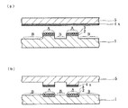
図2は、さらに異なる本発明の態様を表したものである。同図においては、表面に凹凸を有するシリコンウェハ、ガラスなどの絶縁性基板1の凸状領域に分析試薬成分6を担持し、その部分が分析部Aとされている。また分析部Aの周囲の凹状領域に非分析部Bがあり、基板1に対向する対向部に、分析対象物に由来する信号の検出電極部4yが設けられている。
【0053】
この図2の態様の具体的分析手順としては、例えば、特異結合物質を分析部Aに担持させておき、分析対象物を分析する試料液と西洋ワサビパーオキシダーゼ(HRP)標識特異結合物質とを反応させ、試料液中の分析対象物の量に応じた、特異結合物質−分析対象物−HRP標識特異結合物質から成る三元複合体を分析部A上に形成させる特異結合反応を行なわせる。そしてこの分析部Aの三元複合体中のHRP活性を、対向部の信号検出電極部4yで検出する。
【0054】
図1に示した態様と同様に、この場合もHRPの酵素基質である過酸化水素は、電気化学的に発生させてもよく、グルコースオキシダーゼ(GOD)のようなオキシダーゼを用いて発生させてもよく、単に反応溶液中に存在させてもかまわない。なお、分析部AのHRP活性と、検出部電極として機能させる対向部4yとを媒介する電子メディエータが反応溶液中に必要である。
【0055】
このように構成することにより、試料中の分析対象物の量に応じて分析部Aに生成した三元複合体中のHRP活性に起因する信号(例えば、信号検出部電極で観測される還元電流値)は、電子メディエータの拡散距離が大きくなるに従って小さくなり、それ故に、対向部にある信号検出電極部4yでの信号強度は、分析部Aと信号検出電極部4yとの距離が離れるに従い小さくなる。したがって、凸状領域となっている分析部Aに形成された三元複合体中のHRP活性の信号の検出に際して、分析部A以外の領域、即ち、分析部Aの周辺の凹状の非分析部Bへ非特異吸着したHRPの影響を小さくでき、分析部Aにおける精度の高い特異結合分析が可能となる。
【0056】
図2の態様は、絶縁性基板1に凹凸を付与して、凸状の分析部Aとその周囲の凹状の非分析部Bとを形成したが、本発明の態様としては、対向部に凹凸を付与し、信号検出電極部4yとして機能する部位の対向部を分析部Aに近付けてもよい。さらに本発明の態様としては、図2の態様において、分析部Aを電極から構成してもよく、対向部に信号の発生に関与する試薬成分を担持させてもよい。
【0057】
図3はさらに異なる本発明の態様を表したものである。同図においては、表面に凹凸を有する透明基板1の凸状領域である分析部Aに、分析対象物に対する特異結合物質等の反応物質3を担持させ、基板1の対向部4zには、光エネルギーを供給する信号発生関与部として、エバネッセント波を発生する光導波路を設け、また基板1の裏面にはCCDを配したものである。
【0058】
この態様の分析手順としては、まず、分析対象物を分析する試料と蛍光物質標識抗分析対象物抗体とを分析部Aに導入し、分析部A上に三元複合体を形成する。ここで、蛍光物質としては、フルオレセイン、テキサスレッド、フィコビリプロテインなどを例示することができる。次いで、対向部4zからエバネッセント波を発生させる。このエバネッセント波の及ぶ範囲は、波長、屈折率、光の入射角に依存するが、通常100nm以下程度である。したがって、図3の態様においては、エバネッセント波の進行方向の分析部Aと非分析部Bとの距離を100nm以上離すことにより、分析部Aの表面に結合している標識蛍光物質にはエバネッセント波が到達し、その標識蛍光物質は蛍光を発するが、非分析部Bの表面に結合している標識蛍光物質には、エバネッセント波が及ばず、蛍光も発しない。したがって、CCDでは、分析部Aの表面に結合している標識蛍光物質からの蛍光を特異的に検出することが可能となる。
【0059】
なお、図3には、基板の対向部に光エネルギー供給する信号発生関与部を設け、基板の裏面に検出器としてCCDを設けた例を示したが、発明においては、対向部の信号発生関与部からエネルギーを供給する場合でも、検出器を対向部側に設けることができる。例えば、基板の対向部に設けた光導波路が光エネルギーを供給すると共に分析部からの蛍光を検出器に導光するようにしてもよい。また、基板の対向部にサーマルサイクラーを設けた場合に、そのサーマルサイクラーに接する電極を検出器として対向部に設けることができる。
【0060】
以上、本発明の態様を図面に基づいて具体的に説明したが、本発明の分析方法は、上述した特定の分析手法に限定されるものではない。例えば、図1及び図2の具体的態様として説明したような、三元複合体中のHRP活性を利用する分析法は(所謂サンドイッチ型特異結合分析法)は、本発明が使用することのできる分析手法の一例であり、この他、本発明は、競合型特異結合反応にも好適に応用可能である。また、洗浄分離操作の必要な非均質法のみならず、均質法にも好適に応用できる。さらに、特異結合分析のみならず、化学センサ、酵素センサなどのバイオセンサにも応用可能である。
【0061】
ここで、化学センサとしては、イオン選択性電極、ガスセンサ、固体電解質センサ、半導体センサ、湿度センサ、臭いセンサ、その他の試料中の化学物質に感応するセンサ類をあげることができ、化学物質に感応する物質を担持した分析部と、電極、光電素子などのトランスジューサーから構成される検出部を組み合わせて、分析部に担持した物質が感応する化学物質を検出する分析方法が含まれる。
【0062】
バイオセンサとしては、生体組織、微生物、細胞、細胞内小器官などの生物体、あるいは、酵素などの生体触媒物質などを分子識別素子として担持させた分析部と、電極、光電素子などのトランスジューサーから構成される検出部を組み合わせたセンサ等が含まれる。代表的なバイオセンサは酵素センサであり、酵素としてグルコースオキシダーゼ(GOD)を用いたグルコースセンサなどが知られる。
【0063】
本発明が利用できる特異結合分析についても、図1及び図2であげた例に限られず、種々の態様をあげることができる。したがって、特異結合物質としては、抗体、抗原、オリゴヌクレオチドなどの核酸類などの特異結合物質を分析部に担持させ、電極、光電素子などのトランスジューサーから構成される検出部を組み合わせて、分析部に担持した特異結合物質に関連する特異結合反応を検出する分析方法が含まれる。
【0064】
すなわち、特異結合分析は、分析対象物と、それに特異的に結合する特異結合物質との少なくとも1つの特異結合反応に関連して試料中の分析対象物を定性もしくは定量する分析方法である。この特異結合分析としては、抗原抗体反応を応用したイムノアッセイ、受容体を用いたレセプターアッセイ、相補的核酸配列のハイブリダイゼーションを用いた核酸プローブアッセイなどの多くの方法が知られており、その特異性の高さから、臨床検査をはじめとする広い分野で繁用されている。
【0065】
そして特異結合分析における分析対象物としては、具体的には抗体分子や抗原として機能する各種蛋白質、ポリぺプチド、糖蛋白質、多糖類、複合糖脂質、低分子化合物など、あるいは核酸、エフェクター分子、レセプター分子、酵素、インヒビター等が例示される。さらに具体的には、α−フェトプロテイン、癌胎児性抗原(CEA)、CA125、CA19−9等の腫瘍マーカーや、β2 −ミクログロブリン(β2 m)、フェリチンなどの各種蛋白質;エストラジオール(E2 )、ヒト絨毛性性腺刺激ホルモン(hCG)、黄体形成ホルモン(LH)、ヒト胎盤ラクトゲン(hPL)などの各種ホルモン;カビ、細菌などの各種微生物あるいは微生物生産物質;HBs 抗原、HBs 抗体、HBe 抗原、HBe 抗体、HBc 抗体、HCV抗体、HIV抗体などの各種ウイルス関連抗原あるいはウイルス関連抗体;各種アレルゲンおよびこれに特異的なIg E抗体;麻薬性薬物、医療用薬物およびこれらの代謝産物;環境汚染物質、有害物質、危険物質などの環境指標物質;ウイルスおよび疾患関連ポリヌクレオチド配列の核酸等が例示される。
【0066】
また、特異結合分析における特異結合物質としては、分析対象物等のある特定の物質に特異的に結合する、すなわち、特定の物質に特異結合反応しうる物質が包含される。
【0067】
したがって、分析対象物とそれに対する特異結合物質との組み合わせとしては、抗原とそれに対する抗体、相補的核酸配列、エフェクター分子とレセプター分子、酵素とインヒビター、酵素と補因子、酵素と基質、糖鎖を有する化合物とレクチン、ある抗体とその抗体に対する抗体、レセプター分子とそれに対する抗体等が例示される。また、これらの組み合わせにおいて、どちらの物質も相手方の物質に対する特異結合物質となりうる。
【0068】
また、特異結合物質として、特異結合活性が消失しない程度に化学修飾されたもの、あるいは、他の成分と結合してなる複合性物質もあげられる。このような特異結合物質としては、ビオチンで化学修飾された抗体もしくはポリヌクレオチド、アビジン共有結合抗体等が例示される。また、遺伝子組換え法で作成した抗体と酵素、あるいは抗体とレセプターとの融合蛋白質なども例示される。
【0069】
特異結合分析を実施するセンサの一例として、液体試料中の分析対象物と特異結合物質との特異結合反応によって標識剤の電極部からの距離分布を形成させ、電子伝達物質の拡散に律速された液体試料中の分析対象物の濃度に対応する電流値を計測し、これによって分析対象物濃度を測定するMEDIA法(Mediator Diffusion-Controlled Immunoassay) として知られる特異結合分析方法(特開平5−264552号公報(欧州特許公開公報0525 723 A2 号)参照)があるが、本発明においては、このMEDIA法も好ましく利用することができる。
【0070】
以上のような本発明の分析方法において、分析対象物を担持する基板側に凹凸を設けておく態様を実施する場合、使用する基板としては、表面に複数の凸状分析部と各凸状分析部の周囲に凹状の非分析部を形成したものが有用である。特に、その凸状分析部に、分析対象物に対する特異結合物質を担持させたものは、本発明で特異結合分析を利用する場合に有用である。
【0071】
このような基板において、凸状分析部の表面積や、凸状分析部の非分析部からの高さや、隣接する凸状分析部の間隔は、分析対象物の種類等に応じて適宜定めることができるが、例えば、凸状分析部の非分析部からの高さ0.1μm〜1mmとし、隣接する凸状分析部の間隔を2μm〜20mmとすることにより、通常の多項目同時分析や多試料同時分析を、高い分析精度で行うことが可能となる。
【0072】
また、このような凹凸を有する基板は、フォトリソグラフィー法、エッチング法、切削法、蒸着法、貼合わせ法、印刷法などの表面加工法あるいは表面処理法を用いて容易に作製することができる。したがって、本発明の方法によれば、それを実施する装置も容易に製造できるようになる。
【0073】
一方、本発明の方法を実施するにあたり、基板上の分析部等の所定の領域に分析試薬を担持させる場合には、分析精度を向上させるため、所定の領域に正確な量を担持させることが好ましいが、従来の微量分析装置に比して担持量や位置精度に許容範囲をもたせることができる。即ち、分析試薬成分の担持時の反応液が所定領域をはみ出しても、前述のように基板上の分析部上の分析対象物に由来する信号強度は、その周辺部からの信号強度に比して強いので、分析試薬成分の担持量や担持位置の測定精度への影響を小さくできる。したがって、本発明の方法を実施する分析装置は、精密なマイクロセンサとして製造することが可能となる。
【0074】
また、本発明の方法によれば、従来例のように分析試薬成分を基板全体に反応させて、基板上の特定領域(結合官能基を導入した領域など)に分析試薬成分を担持させる方法を採用する必要がなくなる。したがって、マイクロキャピラリーで凸状分析部に分析試薬成分を点着して担持させることが可能となり、それゆえに、分析試薬の無駄を抑制することができる。また、マイクロキャピラリーを用いて分析試薬成分を点着させる場合には、プローブ電極を用いて信号を検出する場合と同様に、マイクロキャピラリーを、基板上を走査させることでき、これにより効率的に点着作業を行えるようになるので好ましい。
【0075】
さらに、マイクロキャピラリーによる点着方式は、多項目同時分析や多試料同時分析のための微小な分析部の形成を可能にするため、本発明によれば多項目同時分析や多試料同時分析も容易に行えるようになる。即ち、多項目同時分析や多試料同時分析を行うためには、基板上の微量な領域に、複数の異なる分析試薬を担持させた分析部を形成したり、多試料あるいは標準試料(濃度既知の試料、陽性試料、陰性試料、対照試料等)を点着させるための複数の分析部を形成することが必要となるが、本発明によればこのような分析部の形成をマイクロキャピラリーを用いて容易に行うことが可能となる。また、点着する内容に応じて、使用するマイクロキャピラリーを交換する、あるいは複数のマイクロキャピラリーを用いて点着する等の操作も容易となる。
【0076】
【実施例】
以下、本発明を実施例に基づいて具体的に説明する。
【0077】
実施例1:特異結合基板を用いたhCG(ヒト絨毛性ゴナドトロピン)及びhPL(ヒト胎盤性ラクトゲン)の多項目同時特異結合分析
【0078】
(1) 溶液の調製
10%HF溶液は、46%フッ化水素酸(森田化学工業社製)を蒸留水で希釈して調製した。オクタデシルトリクロロシラン(関東化学社製)は、ベンゼン(和光純薬工業社製)で希釈して10mM濃度に調製した。
【0079】
フェロセニルメタノ−ル(FMA)は、フェロセニルアルデヒド(アルドリッチ社)を還元して合成した。すなわち、フェロセニルアルデヒド(アルドリッチ社)のエタノール溶液20mLと、0.1gNaOH、1.0gNaBH4 を含有するエタノール溶液30mLとを混合し、1日間還流した。その後、50mLのクロロホルムで抽出し、溶媒のクロロホルムをエバポレートして粗FMAを得、これをn−ヘキサンで3回再結晶させて精製した。
【0080】
マウス単クローン性抗ヒト絨毛性ゴナドトロピン(hCG)抗体、および、マウス単クローン性抗ヒト胎盤性ラクトゲン(hPL)抗体は、持田製薬株式会社製を用いた。抗体溶液は、いずれも0.1Mリン酸緩衝液(pH7.0)で希釈して調製した。
【0081】
(2) 凸状分析部を有する分析用基板の作製
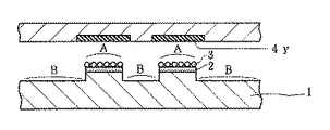
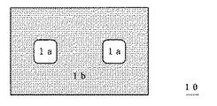
図4(同図(a)上面図、同図(b)断面図)に示すように、方形(50μm×50μm)の凸状分析部1aを2カ所に内包する長方形(150μm×300μm)の凹状非分析部1b、及び、その位置決めのための凹状位置決め部7を有する分析用基板10を次のように作製した。
【0082】
まず、レジスト(OFPR−5000、東京応化社製)をスライドガラス基板(長さ76mm×幅26mm×厚さ0.8〜1.0mm、松浪社製)上にスピンコートした。次いで、オーブン中で60℃30分間プリベークし、その上に予め作製したマスクパターンを密着させ、Hgランプ(500W)で3秒間光照射した。現像液に30秒間浸漬した後、よく水洗することによりレジストマスクがパターニングされたガラス基板を得た。次のこの基板を10%HF溶液に5分間浸すことによってマスクされていない露出ガラス部分を深さ2μmエッチングした。このエッチングにより、深さ2μmの凹状非分析部1bと凹状位置決め部7を形成すると共に、凹状非分析部1b内に凸状分析部1aを残存させた。次に、この基板を蒸留水で洗浄後、メタノールで洗浄してレジストを除去し、再度蒸留水で洗浄して乾燥し、凸状分析部1aを有する分析用基板10を得た。
【0083】
(3) 分析用基板の走査型電気化学顕微鏡(SECM)による観察
基板10に形成した凸状分析部1aのパターンを確認すると共に、後述するようにこの基板10で行う特異結合反応の位置決めのために、走査型電気化学顕微鏡(SECM)で基板10の観察を行った。
【0084】
この場合、走査型電気化学顕微鏡の観察系の構成は、図5に示すように二電極法とし、探針20として、微小プローブ電極(白金電極部の直径5μm,ガラス絶縁部を含むプローブ全体の直径60μm)を使用し、対極21として、飽和塩化カリウム中に浸されたAg/AgC1からなる電極を使用した。
【0085】
ここで、微小プローブ電極は、次のように作製したものを用いた。即ち、直径15μmの白金線をHaNO3 飽和溶液中でエッチングして白金フィラメントを得、これを軟ガラスキャピラリーに挿入し、真空中320℃に加熱封入してガラスコートした。その先端をターンテーブル(成茂科学器械研究所、モデルEG−6)で研磨し、さらに0.05μmアルミナ粒子で研磨することにより、円形断面を有する微小ブローブ電極(白金電極部直径5μm,ガラス絶縁部を含むプローブ全体の直径60μm)を得た。
【0086】
図5の走査型電気化学顕微鏡による観察方法としては、SECMステ−ジ22上に上記(2) で作製した凸状分折部1を有する基板10を載置し、その凸状分折部1a側表面に以下の組成のSECM測定溶液23を滴下することにより、この凸状分折部1a側表面をSECM測定溶液に浸した。
【0087】
[SECM測定溶液組成]
1.0mM フェロセニルメタノール(FMA)
0.1M 塩化カリウム
0.1M リン酸緩衝液(pH7.0)
そして、微小プローブ電極20に+400mV vs.Ag/AgC1の電位を印加し、微小プローブ電極と基板10との距離dを7μmに保持し、9.8μm/秒の走査速度でSECM観察を行った。
【0088】
なお、微小プローブ電極の走査は、サーボモーター駆動のXYZ自動ステ−ジ(以下、モーター駆動アクチュエータと称する)上で行った。自動ステ−ジのサーボモーターを制御するサーボモーターコントローラー(中央精機株式会社製、M9103)は、GPIBバス接続を通じてコンピュータからプログラム制御した。電流は、電流増幅器24(Keithley社製、モデル427)で増幅し、デジタル変換してコンピュータ25に取り込み計測した。
【0089】
観察されたSECM像、即ち、SECM測定溶液中のFMAの酸化電流の二次元プロファイルを図6に示した。このSECM像は、ドットの濃淡で観測された電流を表現しており、ドットの濃い領域が、観測された電流の大きい部分である。この基板10では分析部1aが凸状に突き出しているため、その上を電極が走査するときに電極と分析部との間の距離が狭くなり、FMAの電極への供給が妨げられるので、図示したようにこの部分の電流が小さくなっている。したがって、この図6のSECM像から、基板10には所期の凸状分析部1aと凹状非分析部1bとが形成されていることが確認でき、さらに走査の位置決めをすることができた。
【0090】
(4) 特異結合基板の作製
凸状分折部1を有する分析用基板10を用いて、特異結合分析に使用する特異結合基板を次のように作製した。まず、基板10をオクタデシルトリクロロシランのベンゼン溶液中に1日間浸漬して疎水化処理した。乾燥後、モーター駆動アクチュエータ装置に接続されたガラスキャピラリーにより基板10上の2つの凸状分析部1aのそれぞれに、760μg/mLの抗hCG抗体溶液、あるいは、540μg/mLの抗hPL抗体溶液を約17pLずつ点着した。基板は一晩静置して乾燥後、0.1%Tween20(関東化学社製)水溶液で洗浄後、さらに蒸留水で洗浄した。次に、基板10を10mg/mLウシ血清アルブミン(和光純薬工業社製)水溶液に2時間浸漬してブロッキングを行った後、蒸留水で洗浄した。このようにして凸状分折部1に抗hCG抗体8又は抗hPL抗体9を不溶化した基板10を特異結合基板10aとし、後述する特異結合分析に用いた。この特異結合基板10aの断面模式図を図7に示す。
【0091】
なお、特異結合基板10aを保存する場合、0.1Mリン酸緩衝液(pH7.0)に浸漬して冷蔵保存した。
【0092】
(5) 特異結合基板を用いたhCG(ヒト絨毛性ゴナドトロピン)およびhPL(ヒト胎盤性ラクトゲン)の多項目同時特異結合分析
【0093】
(5-1) 溶液の調製
西洋ワサビパーオキシダーゼ(HRP)標識マウス単クローン性抗hCG抗体、HRP標識マウス単クローン性抗hPL抗体は、持田製薬株式会社製を用いた。また、hCG試料液とhPL試料液は、それぞれ0.1Mリン酸緩衝液(pH7.0)で希釈して調製した。
【0094】
(5-2) 特異結合反応
上記(4) で作製した特異結合基板10aに、20IU/mL濃度のhCG試料液あるいは1.0μg/mL濃度のhPL試料液を5μLずつ点着することにより、特異結合基板10aの凸状分析部1aおよび凹状非分析部1bを上記(5-1) の試料液中に浸漬した。蒸留水で洗浄後、20μg/mLのHRP標識杭hCG抗体および7μg/mLのHRP標識杭hPL抗体を含有する標識杭体溶液に20分間浸漬し、その後、蒸留水で洗浄した。
【0095】
(6) 特異結合基板の走査型電気化学顕微鏡(SECM)測定
走査型電気化学顕微鏡(SECM)を用いて、上記(5-2) の特異結合反応をさせた後の特異結合基板10aの観察を行った。この観察は、上記(3) の分析用基板10の走査型電気化学顕微鏡による観察と略同様に行ったが、SECM測定溶液としては、HRP酵素基質であるH2 O2 を添加した下記の組成の溶液を使用し、プローブ電極に印加する電位は+50mV vs.Ag/AgCIに変更した以外は、上記(3) の方法と同様とした。
【0096】
[SECM測定溶液組成]
1.0mM フェロセニルメタノール(FMA)
0.5mM H2O2
0.1M 塩化カリウム
0.1M リン酸緩衝液(pH7.0)
【0097】
上記(5-1) の試料液として、hPL試料液を用いて特異結合分析を行った場合のSECM像を図8(a)に、また、hCG試料液を用いて特異結合分析を行った場合のSECM像を図9(a)に示した。さらに、図8(a)及び図9(a)のそれぞれのx−x線の切片での電流プロファイルを図8(b)と図9(b)に示した。
【0098】
この結果、抗hCG抗体を不溶化した凸状分析部1aではhCG試料液の場合にのみ標識酵素HRPに起因する酵素触媒還元電流が観測され、逆に、抗hPL抗体を不溶化した凸状分析部ではhPL試料液の場合にのみ標識酵素HRPに起因する酵素触媒還元電流が観測された。したがって、特異結合基板10aにおいて、凹状非分析部1bの微小領域内で、凸状分析部に抗hCG抗体8を不溶化した部分と抗hPL抗体9を不溶化した部分とで交差反応がおきていないことがわかる。
【0099】
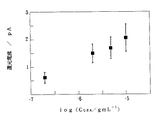
また、hPL試料液とhCG試料液について、それぞれhPL又はhCG濃度を変える以外は同様に特異結合分析を行い、hPL濃度又はhCG濃度の凸状分析部での電流との関係を求めた。これらの結果を図10及び図11に示す。これにより、試料液中の抗原濃度に対応した電流値が得られることがわかる。したがって、本発明の特異結合基板を用いると、試料中の分析対象物を高精度に定量分析できることがわかる。
【0100】
実施例2:特異結合基板を用いたCEA(ヒト癌胎児性抗原)およびAFP(ヒトαフェトプロテイン)の多項目同時特異結合分析
(1) 溶液の調製
マウス単クローン性抗ヒト癌胎児性抗原(CEA)抗体、マウス単クローン性抗ヒトαフェトプロテイン(AFP)抗体、HRP標識マウス単クローン性抗CEA抗体、HRP標識マウス単クローン性抗AFP抗体は、持田製薬株式会社製を用いた。
【0101】
CEA試料液とAFP試料液は、いずれも0.1Mリン酸緩衝液(pH7.0)で希釈して調製した。
【0102】
(2) 特異結合基板の作製
実施例1(2) で作製した凸状分析部を有する分析用基板を用いて特異結合基板を次のように作製した。まず、凸状分析部を有する分析用基板をn−オクタデジルトリクロロシランのベンゼン溶液中に1日間浸漬して疎水化処理した。乾燥後、モーター駆動アクチュエータ装置に接続されたガラスキャピラリーにより基板上の2つの方形の凸状分析部のそれぞれに、635μg/mLの抗AFP抗体溶液、あるいは、512μg/mLの抗CEA抗体溶液を20pLずつ点着した。基板は一晩静置して乾燥後、0.1%Tween20(関東化学社製)水溶液で洗浄後、さらに蒸留水で洗浄した。次に、基板を10mg/mLウシ血清アルブミン(和光純薬工業社製)水溶液に2時間浸漬してブロッキングを行った後、蒸留水で洗浄した。この凸状分析部に抗AFP抗体あるいは抗CEA抗体を不溶化した基板を特異結合基板として、後述する特異結合分析に用いた。
【0103】
特異結合基板を保存する場合は、0.1Mリン酸緩衝液(pH7.0)に浸漬して冷蔵保存した。
【0104】
(3) 特異結合反応
上記(2) で、作製した特異結合基板に50μg/mL濃度のAFP試料液あるいは2×10-9、2×10-8、2×10-7、2×10-6、2×10-5、2×10-4g/mL濃度のCEA試料液を10μLずつ点着し、特異結合基板の凸状分析部および凹状非分析部を試料液中に1時間浸漬した。蒸留水で洗浄後、3.5μg/mLのHRP標識抗AFP抗体および51μg/mLのHRP標識抗CEA抗体を含有する標識抗体溶液に20分間浸漬し、蒸留水で洗浄した。
【0105】
(4) 特異結合基板の走査型電気化学顕微鏡(SECM)測定
実施例1と同一の走査型電気化学顕微鏡(SECM)を用いて、上記(3) で特異結合反応させた特異結合基板の観察を行った。この場合、SECM測定溶液としては、HRP酵素基質であるH2O2 を添加した下記の組成の溶液を使用し、プローブ電極に印加する電位は+50mV vs.Ag/AgCIに変更した以外は、実施例1(3) の方法と同様とした。
【0106】
[SECM測定溶液組成]
1.0mM フェロセニルメタノール(FMA)
0.5mM H2O2
0.1M 塩化カリウム
0.1M リン酸緩衝液(pH7.0)
【0107】
上記(3) の試料液としてAFP試料液を用いて特異結合分析を行った場合のSECM像を図12に示した。また、各種濃度のCEA試料液を用いて特異結合分析を行った場合の還元電流と試料液中のCEA濃度の関係を、図13に示した。
【0108】
この結果から、抗AFP抗体を不溶化した凸状分析部ではAFP試料液の場合にのみ標識酵素HRPに起因する酵素触媒還元電流が観測されたことがわかる(図12)。また、試料液中のCEA濃度に対応した還元電流強度変化が得られた(図13)。したがって、本発明の特異結合基板を用いると、試料中の分析対象物を高精度に定量分析できることが確認できた。
【0109】
比較例1:凸状分析部を有さない特異結合基板を用いたCEA(ヒト癌胎児性抗原)特異結合分析
(1) 溶液の調製
抗体およびHRP標識抗体は、実施例2と同様のものを用いた。
【0110】
CEA試料液は、それぞれ0.1Mリン酸緩衝液(pH7.0)で希釈して調製した。
【0111】
(2) 凸状分析部を有さない基板の作製
スライドガラス基板を10mM濃度のn−オクタデシルトリクロロシランのベンゼン溶液中に8時間浸漬して疎水化処理した。次いで、500μg/mL濃度の単クローン性抗CEA抗体を含有する0.1Mリン酸緩衝液(pH7.0)に2時間浸漬して、スライドガラス表面全体に抗体を不溶化した。蒸留水で洗浄し乾燥して、凸状分析部を有さない分析用基板を作製した。そしてこの基板の表面全体に抗体を不溶化し、比較例の特異結合基板とした。
【0112】
(3) 特異結合反応
モーター駆動アクチュエータ装置に接続したガラスキャピラリーにより、上記(2) で作製した特異結合基板上に100μmの間隔で,2×10-7、2×10⁻⁶、5×10⁻⁶、1×10⁻⁵g/mL濃度のCEA試料液を点着した。その点着スポットのサイズは光学顕微鏡下の観察でほぼ均一(半径約20μm、スポット液量約17pL)であることを確認した。試料液を点着した基板は一晩静置して乾燥後、蒸留水で洗浄した。洗浄後、15μg/mLのHRP標識抗CEA抗体を含有する標識抗体溶液に20分間浸漬し、蒸留水で洗浄した。
【0113】
(4) 特異結合基板の走査型電気化学顕微鏡(SECM)測定
実施例1と同一の走査型電気化学顕微鏡(SECM)を用いて、上記(3) で特異結合反応させた特異結合基板の観察を行った。この場合、SECM測定溶液としては、HRP酵素基質であるH2O2 を添加した下記の組成の溶液を使用し、プロープ電極に印加する電位は+50mV vs.Ag/AgCIに変更した以外は、実施例1(3) の方法と同様とした。
【0114】
[SECM測定溶液組成]
1.0mM フェロセニルメタノール(FMA)
0.5mM H2O2
0.1M 塩化カリウム
0.1M リン酸緩衝液(pH7.0)
【0115】
試料液として、各種濃度のCEA試料液を用いて特異結合分析を行った場合のSECM像を図14に示した。さらに、SECMにおける還元電流と試料液中のCEA濃度との関係を図15に示した。
【0116】
この結果、試料液が点着された部分でのみ、標識酵素HRPに起因するSECM像が観測された(図14)。さらに、試料液中のCEA濃度に対応した還元電流強度変化が得られた(図15)。しかし、図14に示したように、各CEA濃度のSECM像の径が異なり、また各像が完全には分離されていなかった。これは、比較例では、検出部である微小プローブ電極が同一平面上の全ての標識酵素活性を検出してしまうため、分析部の位置及び境界が不鮮明となり、キャピラリーでの試料点着部の面積の誤差の影響などが現れるためと考えられる。したがって、比較例の基板では分析精度を高められないことがわかる。
【0117】
以上により、凸状分析部を有する実施例の特異結合基板を用いると、凸状分析部をもたない比較例の特異結合基板に比して、より精度の高い分析を容易に行えること、特に隣接する凸状分析部で異なる抗体を同時に分析する多項目同時分析を高精度で行えることがわかる。また、実施例の特異結合基板は、基板上の微小領域に微量の抗体を不溶化させることにより作製できるので、分析に使用する抗体量を減少させられることがわかる。
【0118】
【発明の効果】
本発明の分析方法によれば、基板の分析部上で分析対象物と、その分析対象物に直接的又は間接的に反応する反応物質とを反応させ、この反応に由来して発生する信号を検出することにより分析対象物の定性又は定量分析を行うに当たり、分析部上に担持されている物質に由来する信号が、非分析部に担持されている物質に由来する信号に比して強く検出されるので、試料中の分析対象物の高精度な分析が可能となる。
【0119】
また、簡素な装置構成で精密分析を行うことが可能となり、さらに微量の試料で多試料同時分析あるいは多項目同時分析を行うことも可能なる。
【図面の簡単な説明】
【図1】本発明の分析方法の一態様の説明図である。
【図2】本発明の分析方法の他の態様の説明図である。
【図3】本発明の分析方法の他の態様の説明図である。
【図4】実施例で使用した基板の上面図(同図(a))及び断面図(同図(b))である。
【図5】実施例の分析方法の説明図である。
【図6】基板のSECM像を表した図である。
【図7】実施例で使用した特異結合基板の断面図である。
【図8】特異結合基板を用いてhPL試料液を分析した場合のSECM像を表した図(同図(a))及びその電流プロファイル(同図(b))である。
【図9】特異結合基板を用いてhCG試料液を分析した場合のSECM像を表した図(同図(a))及びその電流プロファイル(同図(b))である。
【図10】特異結合基板を用いてhPL試料液を分析した場合の試料液中のhPL濃度と還元電流値との関係図である。
【図11】特異結合基板を用いてhCG試料液を分析した場合の試料液中のhCG濃度と還元電流値との関係図である。
【図12】特異結合基板を用いてAFP試料液を分析した場合のSECM像を表した図である。
【図13】CEA濃度とSECM還元電流との関係図である。
【図14】平坦な基板を用いた比較例のSECM像を表した図である。
【図15】平坦な基板を用いた比較例におけるCEA濃度とSECM還元電流との関係図である。
【符号の説明】
1 基板
1a 分析部
1b 非分析部
2 信号検出電極部
3 分析対象物
4x 信号発生関与部(対向部)
4y 信号検出電極部(対向部)
4z 対向部
6 分析試薬成分
8 抗hCG抗体
9 抗hPL抗体
10 分析用基板
10a 特異結合基板[0001]
BACKGROUND OF THE INVENTION
In the present invention, a qualitative analysis or a quantitative analysis is performed by reacting an analysis object and a reaction material that reacts directly or indirectly with the analysis object on a substrate analysis unit and detecting a signal derived from the reaction. The signal derived from the reaction on the analysis part of the substrate is strongly detected relative to the signal derived from the non-analysis part, which enables highly accurate analysis of the analyte. It relates to the analysis method. More specifically, the present invention relates to an analysis method using a biosensor such as a chemical sensor or an enzyme sensor, a specific binding analysis sensor, or the like, by carrying an analysis object on a convex analysis portion on a substrate, etc. The present invention relates to an analysis method that enables precise analysis with a configuration, and relates to an analysis method that enables manufacture of a microsensor with high accuracy.
[0002]
[Prior art]
Conventional analytical methods for quantifying analytes in the liquid phase or gas phase, such as column chromatographic analysis methods, enzymatic chemical reaction methods, and immunoassay methods, require a large amount of samples for analysis, and are large in analysis. There were problems such as requiring equipment and taking time for analysis. In particular, when there is a need to analyze many samples at the same time (multi-sample simultaneous analysis), or when there is a need to perform multi-item analysis on one sample (multi-item simultaneous analysis), these problems Was a serious obstacle.
[0003]
On the other hand, recently, many sensor technologies such as a chemical sensor, a biosensor, and a specific binding analysis sensor have been developed, and the analysis method is simplified and miniaturized. However, it is still not enough. In particular, no technology has been developed that allows simultaneous analysis of multiple samples or simultaneous analysis of multiple items with a minute sensor and enables high-precision analysis.
[0004]
For example, SPFodor et al., In Science, Vol. 251, p767-773 (1991), combined a photolithographic technique with a light-sensitive protective group to arrange different sequences in a small number of regions (matrix on a two-dimensional plane). A method for synthesizing and using peptides or oligonucleotides for analysis. P. Connolly, in a review of Trends Biotechnol., Vol. 12, p123-127 (1994), introduced photofabrication that uses a lift-off technique to pattern hydrophilic and hydrophobic regions on the substrate surface. ing. CRLowe et al. (USP 4562157), S. Nakamoto et al. (Sensors and Actuators, vol. 13,165-172 (1988)), CSDulcey et al. (Science, Vol. 252, 551-554, 1991), SKBhatia et al. (Anal. Biochem., Vol. 208, 197-205 (1993)) report similar surface processing techniques and analysis methods.
[0005]
WTMuller et al., Science, Vol. 268, p272-273 (1995), microfabricated the surface functional groups of monolayers self-assembled on a substrate with a scanning probe device, Introduces methods for covalently bonding substances to areas.
[0006]
The surface processing technology using the scanning tunneling microscope (STM) is also reported by Y. Utsugi (NATURE, Vol. 347, 747-749 (1990)) and P. Connolly (Nanotechnology, Vol. 2, 160-163 (1991)). ing.
[0007]
DJPritchard et al., Anal.Chim.Acta.Vol.310, p251-256 (1995), applied photo-sensitive biotin and two types of antibodies, respectively, while applying a photomask to a plurality of avidin-insolubilized gold electrodes on a silicon wafer substrate. We have reported a method for producing a specific binding sensor for simultaneous measurement of multiple items.
[0008]
[Problems to be solved by the invention]
Each of these microfabrication techniques makes it possible to fix different substances in a predetermined region on the substrate. However, the manufacturing process is composed of several stages and is complicated. In addition, even though the processing area is small, it is assumed that expensive reagents such as specific binding substances (antibodies) that determine the characteristics of each sensor part or precious molecular identification elements are reacted on the entire substrate, Not necessarily economical. In addition, it is necessary to accurately match the detection region such as the electrode and the immobilization region, and high-precision positioning technology is essential to manufacture a minute sensor. Furthermore, the electrodes, which are detection units, are also unsuitable for highly accurate analysis because they simultaneously detect signals caused by nonspecific binding around the same plane.
[0009]
In addition, in analytical methods represented by specific binding analysis such as biosensors such as chemical sensors and enzyme sensors, and immunosensors, analysis reagent components such as chemical sensitive substances, biocatalytic substances, molecular identification elements, and specific binding substances are supported. And an analysis unit that detects a signal generated by the involvement of the support material. In order to improve the analysis accuracy, it is necessary to improve both the accuracy of the amount of substance carried by the analysis unit and the signal detection accuracy of the detection unit. Here, the accuracy of the amount of substance to be supported by the analysis unit is determined by the loading method (supported in a free state without being chemically bound, supported by a covalent bond, supported by a non-covalent bond, or supported by a specific binding substance. For example), the accuracy of the amount of the reaction liquid to be carried, the accuracy of the amount of the spotted liquid, the accuracy of the carrying area of the analysis unit, and the like. In particular, if the size of the analyzer is reduced in order to enable analysis of a very small amount of sample, it becomes difficult to guarantee the accuracy of the reaction liquid amount or the accuracy of the analysis unit carrying area. Conventionally, in order to solve such a problem, a technique has been adopted in which a substance binding ability is imparted to a minute region on a substrate by a photolithography technique, and the entire substrate is brought into contact with a carrier substance. However, such a method complicates the production process, requires extra reagents to be supported, and is not economical, and is non-specific to a region that should not be supported or bound. The effect of adsorption is inevitable.
[0010]
The present invention is intended to solve such a problem of the prior art, and reacts an analysis object and a reactive substance that reacts directly or indirectly with the analysis object on the analysis part of the substrate, A signal derived from the reaction on the analysis part of the substrate is detected on the non-analysis part when performing a qualitative analysis or quantitative analysis of the analyte in the sample by detecting a signal derived from the reaction. It is an object of the present invention to make it possible to detect an analyte in a sample with high accuracy.
[0011]
In addition, the present invention enables precise analysis with a simple device configuration, facilitating the manufacture of minute and highly accurate microsensors, and enables simultaneous multi-sample analysis or multi-item simultaneous analysis with a small amount of sample. It aims to be.
[0012]
[Means for Solving the Problems]
As a result of diligent investigations on a method for immobilizing a reagent component to be analyzed in a minute region and allowing the component immobilized on the region to be analyzed precisely, Immobilize a reactant that reacts directly or indirectly with the analyte and introduce a sample to analyze the analyte on it, or react them, or place the analyte on the analysis part of the substrate When the analyte is analyzed by introducing a reactant that reacts directly or indirectly with the analyte and reacting them, and detecting a signal derived from this reaction. In this reaction, the distance between the analysis part and the counter part of the substrate is determined when the counter part disposed at the position facing the substrate is closely involved in terms of the supply of reactants or the supply of reaction energy. Substrate non-analysis The signal derived from the reaction on the analysis unit can be detected with a particularly strong intensity, and the reaction on the analysis unit is thus specifically strong. In order to detect the signal intensity, it has been found that it is effective to form irregularities on at least one of the substrate and the opposing portion, and the present invention has been completed.
[0013]
That is, the present invention is caused by reacting an analysis object and a reaction substance that reacts directly or indirectly with the analysis object on the analysis part of the substrate, and originating from this reaction.Selected from light, current and potentialAn analysis method for detecting a signal, comprising at least one of a signal generation participating part and a signal detector involved in generation of the signal at an opposing part as a position facing the substrate at least in a signal detection stage, An unevenness is formed on at least one of the substrate and the facing portion so that the distance between the analyzing portion of the substrate and the facing portion is shorter than the distance between the non-analyzing portion of the substrate and the facing portion. The analysis method is characterized in that a signal derived from the reaction in (2) is detected with a signal intensity stronger than a signal derived from the reaction on the non-analyzing part of the substrate.
[0014]
In addition, the present invention provides an analysis substrate characterized in that a plurality of convex analysis portions are formed on the surface as an analysis substrate useful for carrying out such an analysis method.
[0015]
DETAILED DESCRIPTION OF THE INVENTION
Hereinafter, the present invention will be described in detail.
[0016]
In the analysis method of the present invention, an analysis object and a reaction material that reacts directly or indirectly with the analysis object are reacted on the analysis part of the substrate, and a signal generated from this reaction is detected. And at least one of a signal generation part involved in the generation of the signal and a detector of the signal is provided in a facing part as a position facing the substrate at least in a signal detection stage. Is assumed. In this analysis method, the types of analytes and the types of reactants for the analytes include various substances as described in detail below, and generation of signals generated from these reactions. Regarding the mechanism, the type of signal, the mode of participation of the signal generation involved part in the signal generation, the type and part of the detector for detecting the signal, the signal generated from this reaction is the opposite part and the analysis part. There is no particular limitation as long as it is specifically strengthened according to the distance between and, and various embodiments are included.
[0017]
That is, of the substances that react with the analyte in the present invention, the reactant that reacts directly with the analyte is (i) directly bound to the analyte and itself undergoes a chemical change. Both non-existing substances and (ii) substances that bind directly to the analyte and cause chemical changes to the analyte, the reactant itself or other substances.
[0018]
More specifically, as the substance (i), when the analyte is an antigen, an antibody against the analyte can be mentioned. This is because if the analyte is an antigen, the anti-analyte antibody can directly bind to the analyte.
[0019]
In addition, when the analyte is a nucleic acid having a specific sequence, a poly- or oligonucleotide that hybridizes complementary to the DNA or RNA, a specific binding substance for the analyte to be described later, or an analyte Examples include enzyme molecules that serve as inhibitors and the like. In addition, examples include ionic bond materials having dissociation groups such as carboxylic acid groups and amino groups, and hydrophobic bond materials such as silicon.
[0020]
Examples of the substance (ii) include covalent bond-forming or cross-linkable substances such as glutaraldehyde, carbodiimide, N-hydroxysuccinimid (NHS), disuccinylated starterate (DST), and N-succinimidyl-3- (2-pyridyldithio). Propionate (SPDP) or the like, or a substance having a sulfhydryl group that causes an S—S bond exchange reaction can be exemplified. Furthermore, enzyme molecules that use the analyte as an enzyme substrate, coenzyme, cofactor, inhibitor, etc. can also be exemplified. For example, when the analyte is glucose, which is an enzyme substrate, an enzyme such as glucose oxidase (GOD) binds directly to glucose and D-glucono-δ- in the presence of oxygen, another enzyme substrate. Produces lactone and hydrogen peroxide.
[0021]
On the other hand, in the present invention, a reactive substance that reacts indirectly with an analyte refers to a substance that causes a reaction indirectly related to a reaction involving the analyte. For such substances, (a) substances that bind indirectly to the analyte via a direct binding substance to the analyte, or (b) that do not bind indirectly to the analyte, Includes substances that bind to substances to which the object binds.
[0022]
Among these substances, the substance (a) can be a specific binding substance to the direct binding substance of the analyte, for example, an antibody against the anti-analyte antibody. In the case where biotin is labeled, examples thereof include avidin that specifically binds to the biotin.
[0023]
Examples of the substance (b) include the same substance as the analysis object or an analog of the analysis object. In this case, since the anti-analyte antibody can bind to both the analyte and the substance in (b), the substance in (b) must compete with the analyte for the anti-analyte antibody. It becomes. Examples of the other substance (b) include an enzyme that catalyzes another reaction linked to a reaction catalyzed by an enzyme that can directly react with an analyte. More specifically, when the analyte is glucose and the enzyme that can directly react is GOD, peroxidase (POD) using hydrogen peroxide generated by the GOD reaction as a substrate may be exemplified. it can.
[0024]
In the present invention, the reactant and the analyte that react directly or indirectly with the analysis target as described above are reacted on the analysis unit of the substrate. It can be supported and the other can be introduced thereon. In this case, either the analysis object or the reactant that reacts directly or indirectly with the analysis object may be supported on the substrate in advance. In particular, the analysis object of the substrate is directly connected to the analysis object. It is a multi-sample simultaneous analysis or multi-item simultaneous analysis that supports a reactive substance that reacts automatically or indirectly, introduces a sample for quantitative or qualitative analysis of the analyte to the analysis part of the substrate, and reacts them. This is useful as a practical analysis method.
[0025]
Here, there is no limitation on the mode of carrying the reaction substance as long as it is held in the analysis section in a manner in which a reaction occurs. Therefore, for example, as in the case of simultaneous analysis of multiple samples, a sample solution or a reagent solution is individually introduced into each analysis unit by a dispensing means such as a microcapillary or a suction means, and the sample of each analysis unit on the substrate When the liquids or reagent liquids are not in communication with each other, the reaction substance can be carried in a free state in each analysis unit. On the other hand, when a plurality of different analyzes are performed by simultaneously introducing one sample solution into a plurality of analysis units as in the case of multi-item simultaneous analysis, it is generally preferable to insolubilize the reactants in the analysis unit. . Examples of such insolubilization include an embodiment in which the reactant is insolubilized by physically adsorbing the reactant on the surface of the analyzer or by covalently bonding the reactant to the adsorbent on the surface of the analyzer. Insolubilization methods include glass test tubes, plastic test tubes, porous membranes, microplates, polystyrene beads, latex particles, magnetic particles, etc. Can be suitably used.
[0026]
In the present invention, the signal generated from the reaction between the analyte and the reactant that reacts directly or indirectly with the analyte is either directly or indirectly between the analyte and the analyte. It means a signal generated as a result of direct or indirect reaction with a reactive substance that reacts with, and varies depending on the amount or concentration of the analyte in the sample. For example, when a reactive substance is a specific binding substance and a labeled specific binding substance is involved in signal generation, a signal generated from the label; a specific binding of a polynucleotide sequence that hybridizes with a nucleic acid such as DNA or RNA Examples of the substance include a label-specific binding substance that binds to the product of the hybridization reaction, or a signal generated by an intercalating substance; a signal generated by an enzyme reaction product when the reactive substance is an enzyme, and the like.
[0027]
Here, the signal is represented by an enzyme reaction method, an optical or electrochemical enzyme sensor method, a fluorescence immunoassay method, an enzyme immunoassay method, a chemiluminescence or bioluminescence immunoassay method, and the like. As a detection signal in various analysis methods such as nucleic acid amplification analysis methods typified by various immunoassay methods, nucleic acid hybridization quantification methods using labeled anti-double-chain antibodies or fluorescent intercalators, Various signals such as coloration, light emission such as fluorescence, current, and potential. The signal generation mechanism in these various analytical methods can be used as a preferable one in the present invention. Also in the present invention, the signal intensity depends on the amount or concentration of the analyte in the sample, as in the various measurement methods described above. Therefore, it becomes possible to qualitatively or quantitatively analyze the amount or concentration of the analyte in the unknown sample from the signal intensity detected by the detector.
[0028]
In the present invention, as a detector for detecting a signal as described above, when the signal is based on an electrochemical reaction, for example, a gold electrode formed by vapor deposition on a substrate can be used. A carbon ink or silver paste electrode formed by printing or the like, a carbon fiber electrode, a platinum electrode, or the like can be illustrated as a suitable example. As such an electrode, an electrode in which a portion that is not desired to be exposed is covered with a resist pattern or the like can be used.
[0029]
These electrodes can be used as a current or potential detector by being arranged on the analysis part side on the substrate or on the opposite part side facing the analysis part, but can also be used as an auxiliary electrode. Note that in the case where the electrode is provided in the facing portion, a spacer or the like may be inserted in order to maintain a constant distance between the substrate and the electrode, the substrate and the electrode are opposed to each other via a spacer, and the two are bonded together.
[0030]
In the present invention, as the signal detector, a probe electrode made of an extremely thin platinum filament as described in detail in an embodiment described later may be used. In this case, it is preferable to detect the signal by moving the probe electrode with a precise motor drive so that the probe electrode scans the substrate while maintaining a certain distance from the substrate on which the analysis unit is arranged. This scanning may be performed by moving the substrate side with respect to the probe electrode.
[0031]
The electrochemical detection method using the probe electrode is known as a scanning electrochemical microscope (SECM) (C. Lee, Proc. Natl. Acad. Sci. USA. Vol. 87, p1740-1743). (1990), AJBard et al, Science. Vol. 254, p68-74 (1991), H. Shiku et al. Anal. Chem., Vol. 67, p312-317 (1995), etc.), analysis of the present invention It can be suitably applied to a method.
[0032]
In the present invention, as a signal detector, when the signal is light by fluorescence, chemiluminescence, bioluminescence, or the like, a photodetector such as a CCD or a photomultiplier can be used.
[0033]
The signal detector described above is an example of the embodiment of the present invention, and does not mean that the signal detection method of the present invention is limited to electrochemical detection or optical detection. It is possible to detect a signal with a difference in signal strength between a specific signal of the analysis unit and a non-specific signal around the analysis unit due to at least one unevenness of the analysis unit or the reaction participating unit facing the analysis unit. As much as possible, the present invention can utilize various signal detection methods.
[0034]
On the other hand, in the present invention, the signal generation participating part is anything in proceeding the reaction between the analyte and the substance that reacts directly or indirectly with the analyte and generating a signal derived from the reaction. A portion that controls the supply of the substance that contributes to the above, or a portion that controls the supply of energy involved in the generation of such a signal.
[0035]
Here, controlling the supply of energy means that the supply of external energy necessary for signal generation or the supply of external energy that promotes or suppresses signal generation is controlled. Examples of energy involved in signal generation include light energy and thermal energy.
[0036]
In addition, when energy is supplied from the signal generation part, the energy reaches the analysis part on the substrate sufficiently, but the non-analysis part does not reach an amount effective for promoting the reaction. It is preferable that the supply region can be controlled in the vicinity of the surface of the signal generating part. As an example of the energy that can control the supply region in this way, as the light energy, for example, an evanescent wave generated on the surface of an optical waveguide such as a prism plate or an optical fiber can be given. When evanescent waves are used, the fluorescent substance in the thin layer region can be detected. In addition, when light energy is used, surface plasmon resonance (SPR) analysis based on a change in induction rate on the surface of the metal-deposited optical waveguide can be performed.
[0037]
Therefore, when using an evanescent wave in the present invention, the facing portion constituting the signal generation participating portion is made of an optical waveguide such as a planar prism plate, and at least one of the analyzing portion or the facing portion is a convex region, and the analyzing portion is While entering the region where the light energy is supplied, the non-analyzing part is moved away from the region where the light energy is supplied. Then, by installing a condenser on the substrate side or on the opposite side, and using this in combination with a detector such as a photoelectric amplifier or CCD, it becomes possible to analyze signals originating from the analysis section with high accuracy. .
[0038]
In the present invention, heat energy controlled by a thermal cycler (for example, one used in a DNA amplification device or the like) can also be cited as energy that can control the supply region from the signal generation part. When the thermal cycler is used in the present invention, the temperature near the heat source can be controlled to a predetermined temperature, but the temperature cannot be controlled up to a remote area. On the other hand, nucleic acid amplification reactions such as polymerase chain reaction (PCR) are caused by temperature circulation by a thermal cycler. Therefore, when a thermal cycler is used in the present invention, a convex region may be formed so as to enter a region where only the analysis unit receives the necessary temperature control so that PCR is caused. In order to increase the temperature difference between the inside and outside of this region, the substrate side may be maintained at a constant temperature.
[0039]
More specifically, the embodiment of the present invention using a thermal cycler will be described. For example, a sequence-specific nucleic acid probe is carried in the analysis unit, and a reagent necessary for PCR such as a sample, a primer, and a polymerase is opposed to the analysis unit. The temperature is controlled by a thermal cycler from the opposite part. Then, when the nucleic acid sequence which is an analysis object exists in the sample, nucleic acid amplification is caused only in the analysis unit. Therefore, for example, the label can be incorporated into the nucleic acid amplification product by coexisting a fluorescent labeling substance that intercalates with the double-stranded nucleic acid, or an electrochemically labeled mononucleotide. As a result, it is possible to detect a fluorescent signal or an electrochemical signal corresponding to the product amount of the nucleic acid amplification reaction with a detector. In this case, the nucleic acid amplification reaction itself does not occur unless the temperature is controlled even if a component such as a nucleic acid probe is supported by other than the convex analysis section. Therefore, it is possible to perform measurement at the analysis unit with high accuracy.
[0040]
In the present invention, as described above, when reacting a reactive substance that directly or indirectly reacts with an analysis object and the analysis object on the analysis unit of the substrate, either one of them is analyzed in advance on the substrate. It is possible to carry the other on the substrate, and the other can be introduced onto it. Various aspects are included for the installation site. That is, a signal generation participation part may be provided in the opposite part facing the substrate, and the detector may be provided on the substrate side, or the detector may be provided without providing the signal generation participation part in the opposite part. Both of the signal generation participating unit and the detector may be provided. In addition, when the signal generation participation part is provided in the facing part, the signal generation participation part may supply a substance related to signal generation or supply energy. Hereinafter, these points will be described in detail with reference to the drawings.
[0041]
Fig.1 (a) is explanatory drawing of the one aspect | mode of the analysis method of this invention. In the embodiment shown in the figure, a signal detection electrode comprising a plurality of conductive layers formed of a semiconductor, metal, carbon ink or the like on a convex region of an insulating
[0042]
Further, a signal generation involved portion 4x is disposed at a position facing the insulating
[0043]
The signal
[0044]
As a specific analysis method of the embodiment of FIG. 1, for example, a specific binding substance is loaded in advance in the convex analysis part A as the
[0045]
By comprising in this way, the signal resulting from the HRP activity in the ternary complex produced | generated in the analysis part A according to the quantity of the analyte in a sample (namely, reduction current detected with the signal detection electrode 2) ) Depends on the diffusion of the enzyme substrate of HRP supplied from the signal generation participation unit 4x, and the signal intensity decreases as the distance from the signal generation participation unit 4x increases. Therefore, the detection signal intensity derived from the analysis object carried by the analysis unit A having a short distance to the signal generation participating unit 4x is non-specific adsorption of HRP to a region other than the analysis unit, for example, the non-analysis unit B. The influence received from the above can be reduced, and highly accurate specific binding analysis becomes possible.
[0046]
In the embodiment of FIG. 1 (a), the surface of the insulating
[0047]
The analysis procedure using the analysis substrate of the embodiment shown in FIG. 1A or FIG. 1B can be performed as follows, for example.
[0048]
First, as the
[0049]
Next, a reagent solution necessary for signal generation, for example, an electrolyte solution containing dissolved oxygen and glucose required when GOD is carried on the signal generation participation unit 4x, is transferred to the
[0050]
In the above analysis procedure, the specific mode when introducing the sample, the cleaning liquid, or the reagent liquid is not particularly limited as long as the sample, the cleaning liquid, or the reagent liquid contacts the analysis unit A on the
[0051]
Further, in the above analysis procedure, it is not necessary that the signal generation participation unit 4x faces the analysis unit A at the start of analysis. The signal generation involved unit 4x only needs to face the analysis unit A at the signal generation stage. Therefore, the signal generating part 4x or the dispensing means can be moved on the
[0052]
FIG. 2 illustrates yet another aspect of the present invention. In the figure, an
[0053]
As a specific analysis procedure of the embodiment of FIG. 2, for example, a specific binding substance is supported on the analysis unit A, and a sample solution for analyzing an analysis object and a horseradish peroxidase (HRP) labeled specific binding substance are used. A specific binding reaction is performed in which a ternary complex composed of a specific binding substance-analyte target-HRP-labeled specific binding substance is formed on the analysis part A according to the amount of the analysis target in the sample solution. And the HRP activity in the ternary complex of this analysis part A is detected by the signal detection electrode part 4y of the opposing part.
[0054]
Similar to the embodiment shown in FIG. 1, hydrogen peroxide, which is the HRP enzyme substrate, may be generated electrochemically or using an oxidase such as glucose oxidase (GOD). Well, it may simply be present in the reaction solution. Note that an electron mediator that mediates the HRP activity of the analysis unit A and the facing unit 4y that functions as the detection unit electrode is required in the reaction solution.
[0055]
With this configuration, a signal (for example, a reduction current observed at the signal detection unit electrode) caused by the HRP activity in the ternary complex generated in the analysis unit A according to the amount of the analyte in the sample. Value) decreases as the diffusion distance of the electron mediator increases, and therefore, the signal intensity at the signal detection electrode unit 4y located at the opposing portion decreases as the distance between the analysis unit A and the signal detection electrode unit 4y increases. Become. Therefore, when detecting the signal of HRP activity in the ternary complex formed in the analysis part A which is a convex area, the area other than the analysis part A, that is, the concave non-analysis part around the analysis part A The influence of non-specifically adsorbed HRP on B can be reduced, and the specific binding analysis with high accuracy in the analysis part A becomes possible.
[0056]
In the embodiment of FIG. 2, the insulating
[0057]
FIG. 3 illustrates yet another aspect of the present invention. In the figure, a
[0058]
As an analysis procedure of this embodiment, first, a sample for analyzing an analysis object and a fluorescent substance-labeled anti-analysis object antibody are introduced into the analysis part A, and a ternary complex is formed on the analysis part A. Here, examples of the fluorescent substance include fluorescein, Texas red, and phycobiliprotein. Next, an evanescent wave is generated from the facing portion 4z. The range covered by the evanescent wave depends on the wavelength, refractive index, and incident angle of light, but is usually about 100 nm or less. Therefore, in the embodiment of FIG. 3, the distance between the analysis part A and the non-analysis part B in the traveling direction of the evanescent wave is increased by 100 nm or more so that the labeled fluorescent substance bound to the surface of the analysis part A is not the evanescent wave. And the labeled fluorescent substance emits fluorescence, but the labeled fluorescent substance bound to the surface of the non-analyzing part B does not reach the evanescent wave and does not emit fluorescence. Therefore, the CCD can specifically detect the fluorescence from the labeled fluorescent substance bound to the surface of the analysis unit A.
[0059]
FIG. 3 shows an example in which a signal generation part for supplying light energy is provided at the opposite part of the substrate and a CCD is provided as a detector on the back surface of the substrate. Even when energy is supplied from the part, the detector can be provided on the facing part side. For example, an optical waveguide provided on the opposite part of the substrate may supply light energy and guide the fluorescence from the analysis part to the detector. In addition, when a thermal cycler is provided at the facing portion of the substrate, an electrode in contact with the thermal cycler can be provided at the facing portion as a detector.
[0060]
As mentioned above, although the aspect of this invention was concretely demonstrated based on drawing, the analysis method of this invention is not limited to the specific analysis method mentioned above. For example, the analysis method using the HRP activity in the ternary complex (so-called sandwich type specific binding analysis method) as described in the specific embodiment of FIGS. 1 and 2 can be used by the present invention. This is an example of an analysis technique, and besides this, the present invention can be suitably applied to competitive specific binding reactions. Moreover, it can be suitably applied not only to non-homogeneous methods requiring washing and separating operations but also to homogeneous methods. Furthermore, it can be applied not only to specific binding analysis but also to biosensors such as chemical sensors and enzyme sensors.
[0061]
Examples of chemical sensors include ion-selective electrodes, gas sensors, solid electrolyte sensors, semiconductor sensors, humidity sensors, odor sensors, and other sensors that are sensitive to chemical substances in the sample. And an analysis method for detecting a chemical substance to which the substance carried on the analysis unit is sensitive by combining an analysis unit carrying the substance to be detected and a detection unit including a transducer such as an electrode and a photoelectric element.
[0062]
Biosensors include biological tissues, microorganisms, cells, biological organs such as cells, organelles, or biocatalytic substances such as enzymes as molecular identification elements, and transducers such as electrodes and photoelectric elements. The sensor etc. which combined the detection part comprised from are included. A typical biosensor is an enzyme sensor, and a glucose sensor using glucose oxidase (GOD) as an enzyme is known.
[0063]
The specific binding analysis that can be used in the present invention is not limited to the examples shown in FIGS. 1 and 2, and various modes can be mentioned. Therefore, as the specific binding substance, a specific binding substance such as an antibody, antigen, oligonucleotide or other nucleic acid is carried in the analysis unit, and a detection unit composed of a transducer such as an electrode or a photoelectric element is combined with the analysis unit. And an analytical method for detecting a specific binding reaction associated with the specific binding substance carried on the carrier.
[0064]
That is, the specific binding analysis is an analysis method for qualitatively or quantitatively analyzing an analyte in a sample in relation to at least one specific binding reaction between the analyte and a specific binding substance that specifically binds to the analyte. For this specific binding analysis, there are many known methods such as immunoassay applying antigen-antibody reaction, receptor assay using receptor, and nucleic acid probe assay using hybridization of complementary nucleic acid sequences. Because of its height, it is frequently used in a wide range of fields including clinical tests.
[0065]
Specifically, the analyte in the specific binding analysis includes various proteins, polypeptides, glycoproteins, polysaccharides, complex glycolipids, low molecular compounds, etc. that function as antibody molecules or antigens, nucleic acids, effector molecules, Examples include receptor molecules, enzymes, inhibitors and the like. More specifically, tumor markers such as α-fetoprotein, carcinoembryonic antigen (CEA), CA125, CA19-9, β2-Microglobulin (β2m), various proteins such as ferritin; estradiol (E2), Various hormones such as human chorionic gonadotropin (hCG), luteinizing hormone (LH), human placental lactogen (hPL); various microorganisms such as fungi and bacteria, or microorganism-producing substances; Various virus-related antigens or virus-related antibodies such as HBe antibody, HBc antibody, HCV antibody, HIV antibody; various allergens and Ig E antibodies specific thereto; narcotic drugs, medical drugs and their metabolites; environmental pollution Examples include environmental indicator substances such as substances, toxic substances, and dangerous substances; nucleic acids of viruses and disease-related polynucleotide sequences, and the like.
[0066]
The specific binding substance in the specific binding analysis includes a substance that specifically binds to a specific substance such as an analysis object, that is, a substance that can specifically bind to a specific substance.
[0067]
Therefore, a combination of an analyte and a specific binding substance includes an antigen and an antibody thereto, a complementary nucleic acid sequence, an effector molecule and a receptor molecule, an enzyme and an inhibitor, an enzyme and a cofactor, an enzyme and a substrate, and a sugar chain. Examples thereof include compounds having lectins, certain antibodies and antibodies to the antibodies, receptor molecules and antibodies to the same. Further, in these combinations, either substance can be a specific binding substance for the other substance.
[0068]
Examples of the specific binding substance include those that are chemically modified to such an extent that the specific binding activity does not disappear, or composite substances that are bound to other components. Examples of such a specific binding substance include an antibody or polynucleotide chemically modified with biotin, an avidin covalently bound antibody, and the like. Moreover, the fusion protein of the antibody and enzyme produced by the gene recombination method, or an antibody and a receptor etc. are illustrated.
[0069]
As an example of a sensor that performs specific binding analysis, the distance distribution from the electrode part of the labeling agent is formed by the specific binding reaction between the analyte in the liquid sample and the specific binding substance, and is controlled by the diffusion of the electron transfer substance. A specific binding analysis method known as a MEDIA method (Mediator Diffusion-Controlled Immunoassay) for measuring the current value corresponding to the concentration of the analyte in the liquid sample and thereby measuring the analyte concentration (Japanese Patent Laid-Open No. 5-264552) (See European Patent Publication No. 0525 723 A2), but in the present invention, this MEDIA method can also be preferably used.
[0070]
In the analysis method of the present invention as described above, when implementing an embodiment in which unevenness is provided on the substrate side carrying the analysis object, the substrate to be used is a plurality of convex analysis parts on the surface and each convex analysis What formed the concave non-analysis part around the part is useful. In particular, those having a specific binding substance for an analyte to be supported on the convex analysis portion are useful when using specific binding analysis in the present invention.
[0071]
In such a substrate, the surface area of the convex analysis unit, the height of the convex analysis unit from the non-analysis unit, and the interval between adjacent convex analysis units can be determined as appropriate according to the type of the analyte. However, for example, by setting the height from the non-analysis part of the convex analysis part to 0.1 μm to 1 mm and the interval between adjacent convex analysis parts to 2 μm to 20 mm, normal multi-item simultaneous analysis and multiple samples Simultaneous analysis can be performed with high analysis accuracy.
[0072]
In addition, a substrate having such unevenness can be easily manufactured by using a surface processing method such as a photolithography method, an etching method, a cutting method, a vapor deposition method, a bonding method, or a printing method, or a surface treatment method. Therefore, according to the method of the present invention, an apparatus for performing the method can be easily manufactured.
[0073]
On the other hand, when carrying out the method of the present invention, when an analysis reagent is carried in a predetermined region such as an analysis unit on a substrate, an accurate amount may be carried in the predetermined region in order to improve analysis accuracy. Although it is preferable, an allowable range can be given to the carrying amount and the position accuracy as compared with the conventional microanalyzer. In other words, even if the reaction liquid at the time of loading of the analysis reagent component protrudes from the predetermined area, the signal intensity derived from the analysis target on the analysis part on the substrate as compared with the signal intensity from the peripheral part as described above. Therefore, the influence on the measurement accuracy of the loading amount and loading position of the analysis reagent component can be reduced. Therefore, the analyzer that performs the method of the present invention can be manufactured as a precise microsensor.
[0074]
In addition, according to the method of the present invention, a method in which an analysis reagent component is allowed to react with the entire substrate as in the conventional example, and the analysis reagent component is supported on a specific region (such as a region into which a binding functional group has been introduced) on the substrate. No need to adopt. Therefore, it becomes possible to spot and carry the analysis reagent component on the convex analysis portion with the microcapillary, and therefore, waste of the analysis reagent can be suppressed. In addition, when spotting an analysis reagent component using a microcapillary, the microcapillary can be scanned over the substrate in the same manner as when a signal is detected using a probe electrode. This is preferable because it allows the wearing operation to be performed.
[0075]
Furthermore, the spotting method using a microcapillary makes it possible to form a microanalyzer for multi-item simultaneous analysis and multi-sample simultaneous analysis. According to the present invention, multi-item simultaneous analysis and multi-sample simultaneous analysis are easy. Will be able to do. In other words, in order to perform multi-item simultaneous analysis and multi-sample simultaneous analysis, an analysis part carrying a plurality of different analysis reagents is formed in a minute area on a substrate, or a multi-sample or standard sample (concentration known) is formed. Samples, positive samples, negative samples, control samples, etc.) need to be formed, and according to the present invention, such analysis units are formed using microcapillaries. It can be easily performed. Further, according to the contents to be spotted, operations such as exchanging the microcapillaries to be used or spotting using a plurality of microcapillaries are facilitated.
[0076]
【Example】
Hereinafter, the present invention will be specifically described based on examples.
[0077]
Example 1: Multi-item simultaneous specific binding analysis of hCG (human chorionic gonadotropin) and hPL (human placental lactogen) using a specific binding substrate
[0078]
(1) Solution preparation
The 10% HF solution was prepared by diluting 46% hydrofluoric acid (manufactured by Morita Chemical Co., Ltd.) with distilled water. Octadecyltrichlorosilane (manufactured by Kanto Chemical Co., Inc.) was diluted with benzene (manufactured by Wako Pure Chemical Industries, Ltd.) to prepare a concentration of 10 mM.
[0079]
Ferrocenyl methanol (FMA) was synthesized by reducing ferrocenyl aldehyde (Aldrich). That is, 20 mL of ethanol solution of ferrocenyl aldehyde (Aldrich), 0.1 g NaOH, 1.0 g NaBHFourThe mixture was mixed with 30 mL of an ethanol solution containing and refluxed for 1 day. Thereafter, extraction with 50 mL of chloroform was performed, and the solvent, chloroform, was evaporated to obtain crude FMA, which was purified by recrystallization with n-hexane three times.
[0080]
The mouse monoclonal anti-human chorionic gonadotropin (hCG) antibody and the mouse monoclonal anti-human placental lactogen (hPL) antibody were manufactured by Mochida Pharmaceutical Co., Ltd. All antibody solutions were prepared by diluting with 0.1 M phosphate buffer (pH 7.0).
[0081]
(2) Fabrication of analysis substrate with convex analysis section
As shown in FIG. 4 (top view of FIG. 4 (a), cross-sectional view of FIG. 4 (b)), rectangular (150 μm × 300 μm) concave shapes containing square (50 μm × 50 μm) convex analysis portions 1a in two places. The
[0082]
First, a resist (OFPR-5000, manufactured by Tokyo Ohka Co., Ltd.) was spin-coated on a slide glass substrate (length 76 mm × width 26 mm × thickness 0.8 to 1.0 mm, manufactured by Matsunami). Next, prebaking was performed at 60 ° C. for 30 minutes in an oven, and a mask pattern prepared in advance was brought into close contact therewith and irradiated with light with a Hg lamp (500 W) for 3 seconds. After immersing in the developer for 30 seconds, the glass substrate on which the resist mask was patterned was obtained by thoroughly washing with water. The substrate was then immersed in a 10% HF solution for 5 minutes to etch the unmasked exposed glass portion to a depth of 2 μm. By this etching, a concave non-analyzing portion 1b and a
[0083]
(3) Observation of substrate for analysis by scanning electrochemical microscope (SECM)
In addition to confirming the pattern of the convex analysis portion 1a formed on the
[0084]
In this case, the configuration of the observation system of the scanning electrochemical microscope is a two-electrode method as shown in FIG. 5, and the
[0085]
Here, the microprobe electrode produced as follows was used. That is, a platinum wire with a diameter of 15 μm is replaced with HaNOThreeEtching was performed in a saturated solution to obtain a platinum filament, which was inserted into a soft glass capillary and sealed by heating at 320 ° C. in a vacuum. The tip is polished with a turntable (Narimo Scientific Research Institute, Model EG-6), and further polished with 0.05 μm alumina particles to form a microprobe electrode having a circular cross section (
[0086]
As an observation method using the scanning electrochemical microscope of FIG. 5, the
[0087]
[SECM measurement solution composition]
1.0 mM ferrocenylmethanol (FMA)
0.1M potassium chloride
0.1M phosphate buffer (pH 7.0)
Then, +400 mV vs. the
[0088]
The scanning of the micro probe electrode was performed on an XYZ automatic stage (hereinafter referred to as a motor driven actuator) driven by a servo motor. A servo motor controller (M9103, manufactured by Chuo Seiki Co., Ltd.) that controls the servo motor of the automatic stage was program-controlled from a computer through GPIB bus connection. The current was amplified by a current amplifier 24 (Keithley, model 427), converted into a digital signal, and taken into a
[0089]
The observed SECM image, that is, the two-dimensional profile of the oxidation current of FMA in the SECM measurement solution is shown in FIG. This SECM image represents the current observed by the density of the dots, and the dark area of the dots is a portion where the observed current is large. In this
[0090]
(4) Production of specific binding substrate
A specific binding substrate used for specific binding analysis was prepared as follows using the
[0091]
In addition, when storing the specific binding substrate 10a, the substrate was immersed in 0.1M phosphate buffer (pH 7.0) and stored refrigerated.
[0092]
(5) Multi-item simultaneous specific binding analysis of hCG (human chorionic gonadotropin) and hPL (human placental lactogen) using specific binding substrate
[0093]
(5-1) Solution preparation
Mochida Pharmaceutical Co., Ltd. was used as a horseradish peroxidase (HRP) -labeled mouse monoclonal anti-hCG antibody and an HRP-labeled mouse monoclonal anti-hPL antibody. The hCG sample solution and the hPL sample solution were prepared by diluting with 0.1 M phosphate buffer (pH 7.0).
[0094]
(5-2) Specific binding reaction
By spotting 5 μL each of the hCG sample solution with a concentration of 20 IU / mL or the hPL sample solution with a concentration of 1.0 μg / mL on the specific binding substrate 10 a produced in (4) above, the convex analysis portion of the specific binding substrate 10 a 1a and the concave non-analyzing part 1b were immersed in the sample liquid of the above (5-1). After washing with distilled water, it was immersed in a labeled pile body solution containing 20 μg / mL HRP-labeled pile hCG antibody and 7 μg / mL HRP-labeled pile hPL antibody for 20 minutes, and then washed with distilled water.
[0095]
(6) Scanning electrochemical microscope (SECM) measurement of specific binding substrate
Using a scanning electrochemical microscope (SECM), the specific binding substrate 10a after the specific binding reaction of the above (5-2) was observed. This observation was performed in substantially the same manner as the observation of the
[0096]
[SECM measurement solution composition]
1.0 mM ferrocenylmethanol (FMA)
0.5 mM H2O2
0.1M potassium chloride
0.1M phosphate buffer (pH 7.0)
[0097]
Fig. 8 (a) shows the SECM image when the specific binding analysis is performed using the hPL sample solution as the sample solution of (5-1) above, and the specific binding analysis is performed using the hCG sample solution. The SECM image is shown in FIG. Furthermore, the current profile at the intercept of each xx line of Fig.8 (a) and FIG.9 (a) was shown to FIG.8 (b) and FIG.9 (b).
[0098]
As a result, the enzyme-catalyzed reduction current caused by the labeled enzyme HRP is observed only in the case of the hCG sample solution in the convex analysis unit 1a in which the anti-hCG antibody is insolubilized, and conversely in the convex analysis unit in which the anti-hPL antibody is insolubilized. Only in the case of the hPL sample solution, an enzyme-catalyzed reduction current due to the labeled enzyme HRP was observed. Therefore, in the specific binding substrate 10a, there is no cross-reaction between the portion in which the anti-hCG antibody 8 is insolubilized in the convex analysis portion and the portion in which the
[0099]
Further, specific binding analysis was performed on the hPL sample solution and the hCG sample solution, except that the hPL concentration or the hCG concentration was changed, respectively, and the relationship between the hPL concentration or the hCG concentration and the current at the convex analysis portion was obtained. These results are shown in FIGS. Thereby, it is understood that a current value corresponding to the antigen concentration in the sample solution can be obtained. Therefore, it can be seen that when the specific binding substrate of the present invention is used, the analysis object in the sample can be quantitatively analyzed with high accuracy.
[0100]
Example 2: Multi-item simultaneous specific binding analysis of CEA (human carcinoembryonic antigen) and AFP (human α-fetoprotein) using a specific binding substrate
(1) Solution preparation
Mouse monoclonal anti-human carcinoembryonic antigen (CEA) antibody, mouse monoclonal anti-human α-fetoprotein (AFP) antibody, HRP-labeled mouse monoclonal anti-CEA antibody, HRP-labeled mouse monoclonal anti-AFP antibody Made by Pharmaceutical Co., Ltd. was used.
[0101]
Both the CEA sample solution and the AFP sample solution were prepared by diluting with 0.1 M phosphate buffer (pH 7.0).
[0102]
(2) Production of specific binding substrate
A specific binding substrate was prepared as follows using the analysis substrate having the convex analysis section prepared in Example 1 (2). First, an analysis substrate having a convex analysis part was immersed in a benzene solution of n-octadecyltrichlorosilane for 1 day to be hydrophobized. After drying, 20 pL of 635 μg / mL anti-AFP antibody solution or 512 μg / mL anti-CEA antibody solution is applied to each of the two square convex analysis parts on the substrate by a glass capillary connected to a motor-driven actuator device. I spotted it one by one. The substrate was allowed to stand overnight, dried, washed with an aqueous solution of 0.1% Tween 20 (manufactured by Kanto Chemical Co.), and further washed with distilled water. Next, the substrate was immersed in an aqueous solution of 10 mg / mL bovine serum albumin (manufactured by Wako Pure Chemical Industries, Ltd.) for 2 hours for blocking, and then washed with distilled water. A substrate in which the anti-AFP antibody or anti-CEA antibody was insolubilized in this convex analysis portion was used as a specific binding substrate and used for specific binding analysis described later.
[0103]
When storing the specific binding substrate, the substrate was immersed in 0.1 M phosphate buffer (pH 7.0) and stored refrigerated.
[0104]
(3) Specific binding reaction
In the above (2), an AFP sample solution having a concentration of 50 μg / mL or 2 × 10-92 × 10-82 × 10-72 × 10-62 × 10-Five2 × 10-Four10 μL of CEA sample solution having a concentration of g / mL was spotted at a time, and the convex analysis portion and the concave non-analysis portion of the specific binding substrate were immersed in the sample solution for 1 hour. After washing with distilled water, it was immersed in a labeled antibody solution containing 3.5 μg / mL HRP-labeled anti-AFP antibody and 51 μg / mL HRP-labeled anti-CEA antibody for 20 minutes and washed with distilled water.
[0105]
(4) Scanning electrochemical microscope (SECM) measurement of specific binding substrates
Using the same scanning electrochemical microscope (SECM) as in Example 1, the specific binding substrate subjected to the specific binding reaction in the above (3) was observed. In this case, the SECM measurement solution is HRP enzyme substrate H.2O2Is used, and the potential applied to the probe electrode is +50 mV vs.. Except for changing to Ag / AgCI, the procedure was the same as in Example 1 (3).
[0106]
[SECM measurement solution composition]
1.0 mM ferrocenylmethanol (FMA)
0.5 mM H2O2
0.1M potassium chloride
0.1M phosphate buffer (pH 7.0)
[0107]
FIG. 12 shows an SECM image when specific binding analysis is performed using the AFP sample solution as the sample solution of (3) above. Further, FIG. 13 shows the relationship between the reduction current and the CEA concentration in the sample solution when specific binding analysis was performed using various concentrations of the CEA sample solution.
[0108]
From this result, it can be seen that the enzyme-catalyzed reduction current due to the labeled enzyme HRP was observed only in the case of the AFP sample solution in the convex analysis part in which the anti-AFP antibody was insolubilized (FIG. 12). Further, a reduction current intensity change corresponding to the CEA concentration in the sample solution was obtained (FIG. 13). Therefore, it was confirmed that when the specific binding substrate of the present invention was used, the analysis object in the sample could be quantitatively analyzed with high accuracy.
[0109]
Comparative Example 1: CEA (human carcinoembryonic antigen) specific binding analysis using a specific binding substrate without a convex analyzer
(1) Solution preparation
The same antibody and HRP-labeled antibody as in Example 2 were used.
[0110]
Each CEA sample solution was prepared by diluting with 0.1 M phosphate buffer (pH 7.0).
[0111]
(2) Fabrication of substrate without convex analysis part
The slide glass substrate was hydrophobized by immersing it in a benzene solution of 10 mM n-octadecyltrichlorosilane for 8 hours. Subsequently, the antibody was insolubilized on the entire surface of the slide glass by immersing in 0.1 M phosphate buffer (pH 7.0) containing a monoclonal anti-CEA antibody at a concentration of 500 μg / mL for 2 hours. The substrate for analysis which does not have a convex analysis part was produced by washing with distilled water and drying. Then, the antibody was insolubilized on the entire surface of this substrate to obtain a specific binding substrate of Comparative Example.
[0112]
(3) Specific binding reaction
The glass capillary connected to the motor-driven actuator device is 2 × 10 2 on the specific binding substrate prepared in the above (2) at an interval of 100 μm.-72 × 10-65 × 10-61 × 10-FiveA CE / sample solution with a concentration of g / mL was spotted. The size of the spot spot was confirmed to be almost uniform (radius: about 20 μm, spot liquid amount: about 17 pL) by observation under an optical microscope. The substrate on which the sample solution was spotted was left to stand overnight, dried, and then washed with distilled water. After washing, the membrane was immersed in a labeled antibody solution containing 15 μg / mL HRP-labeled anti-CEA antibody for 20 minutes and washed with distilled water.
[0113]
(4) Scanning electrochemical microscope (SECM) measurement of specific binding substrates
Using the same scanning electrochemical microscope (SECM) as in Example 1, the specific binding substrate subjected to the specific binding reaction in the above (3) was observed. In this case, the SECM measurement solution is HRP enzyme substrate H.2O2Is used, and the potential applied to the probe electrode is +50 mV vs.. Except for changing to Ag / AgCI, the procedure was the same as in Example 1 (3).
[0114]
[SECM measurement solution composition]
1.0 mM ferrocenylmethanol (FMA)
0.5 mM H2O2
0.1M potassium chloride
0.1M phosphate buffer (pH 7.0)
[0115]
FIG. 14 shows SECM images when specific binding analysis was performed using various concentrations of CEA sample solution as the sample solution. Furthermore, the relationship between the reduction current in SECM and the CEA concentration in the sample solution is shown in FIG.
[0116]
As a result, an SECM image attributed to the labeling enzyme HRP was observed only in the portion where the sample solution was spotted (FIG. 14). Furthermore, a reduction current intensity change corresponding to the CEA concentration in the sample solution was obtained (FIG. 15). However, as shown in FIG. 14, the diameters of the SECM images at the respective CEA concentrations were different, and the images were not completely separated. This is because, in the comparative example, the microprobe electrode serving as the detection unit detects all the labeling enzyme activities on the same plane, so the position and boundary of the analysis unit become unclear, and the area of the sample spotting portion on the capillary This is thought to be due to the effects of errors. Therefore, it can be seen that the analysis accuracy cannot be increased with the substrate of the comparative example.
[0117]
As described above, when the specific binding substrate of the example having the convex analysis unit is used, it is possible to easily perform a more accurate analysis as compared with the specific binding substrate of the comparative example having no convex analysis unit. It can be seen that the multi-item simultaneous analysis in which different antibodies are simultaneously analyzed in the adjacent convex analysis section can be performed with high accuracy. Moreover, since the specific binding substrate of an Example can be produced by insolubilizing a small amount of antibody in a minute region on the substrate, it can be seen that the amount of antibody used for analysis can be reduced.
[0118]
【The invention's effect】
According to the analysis method of the present invention, the analysis target of the substrate is reacted with a reaction substance that reacts directly or indirectly with the analysis target, and a signal generated from this reaction is generated. When performing qualitative or quantitative analysis of an analyte by detection, the signal derived from the substance carried on the analysis unit is detected more strongly than the signal derived from the substance carried on the non-analysis unit. Therefore, it is possible to analyze the analysis target in the sample with high accuracy.
[0119]
In addition, precise analysis can be performed with a simple apparatus configuration, and multisample simultaneous analysis or multiitem simultaneous analysis can be performed with a small amount of sample.
[Brief description of the drawings]
FIG. 1 is an explanatory diagram of one embodiment of an analysis method of the present invention.
FIG. 2 is an explanatory diagram of another embodiment of the analysis method of the present invention.
FIG. 3 is an explanatory diagram of another embodiment of the analysis method of the present invention.
FIG. 4 is a top view (FIG. 4A) and a cross-sectional view (FIG. 4B) of a substrate used in Examples.
FIG. 5 is an explanatory diagram of an analysis method of an example.
FIG. 6 is a view showing an SECM image of a substrate.
FIG. 7 is a cross-sectional view of a specific binding substrate used in Examples.
FIG. 8 is a view (FIG. 8 (a)) and a current profile (FIG. 8 (b)) showing an SECM image when an hPL sample solution is analyzed using a specific binding substrate.
FIG. 9 is a view (FIG. 9 (a)) and a current profile (FIG. 9 (b)) showing an SECM image when an hCG sample solution is analyzed using a specific binding substrate.
FIG. 10 is a graph showing the relationship between the hPL concentration in the sample solution and the reduction current value when the hPL sample solution is analyzed using the specific binding substrate.
FIG. 11 is a diagram showing the relationship between the hCG concentration in a sample solution and the reduction current value when an hCG sample solution is analyzed using a specific binding substrate.
FIG. 12 is a view showing an SECM image when an AFP sample solution is analyzed using a specific binding substrate.
FIG. 13 is a relationship diagram between CEA concentration and SECM reduction current.
FIG. 14 is a view showing an SECM image of a comparative example using a flat substrate.
FIG. 15 is a relationship diagram between CEA concentration and SECM reduction current in a comparative example using a flat substrate.
[Explanation of symbols]
1 Substrate
1a Analysis Department
1b Non-analysis part
2 Signal detection electrode
3 Analytical objects
4x Signal generation part (opposite part)
4y Signal detection electrode part (opposite part)
4z opposite part
6 Analytical reagent components
8 Anti-hCG antibody
9 Anti-hPL antibody
10 Analysis substrate
10a Specific binding substrate
Claims (16)
Priority Applications (7)
| Application Number | Priority Date | Filing Date | Title |
|---|---|---|---|
| JP10394896A JP3764779B2 (en) | 1996-03-30 | 1996-03-30 | Analysis method using convex regions |
| EP96117192A EP0798561B1 (en) | 1996-03-30 | 1996-10-25 | Analytical method for precise analysis with a simple sensor |
| AT96117192T ATE326013T1 (en) | 1996-03-30 | 1996-10-25 | ANALYTICAL METHOD FOR PRECISE ANALYSIS USING A SIMPLE SENSOR |
| US08/738,114 US5866321A (en) | 1996-03-30 | 1996-10-25 | Analytical method and device for precise analysis with a simple sensor |
| EP03011765A EP1336849A3 (en) | 1996-03-30 | 1996-10-25 | Analytical method and device for precise analysis with a simple sensor |
| DE69636113T DE69636113D1 (en) | 1996-03-30 | 1996-10-25 | Analytical method for precise analysis with a simple sensor |
| CA002188848A CA2188848C (en) | 1996-03-30 | 1996-10-25 | Analytical method and device for precise analysis with a simple sensor |
Applications Claiming Priority (1)
| Application Number | Priority Date | Filing Date | Title |
|---|---|---|---|
| JP10394896A JP3764779B2 (en) | 1996-03-30 | 1996-03-30 | Analysis method using convex regions |
Related Child Applications (1)
| Application Number | Title | Priority Date | Filing Date |
|---|---|---|---|
| JP2005082161A Division JP2005181350A (en) | 2005-03-22 | 2005-03-22 | Analyzing method using projecting region |
Publications (2)
| Publication Number | Publication Date |
|---|---|
| JPH09269325A JPH09269325A (en) | 1997-10-14 |
| JP3764779B2 true JP3764779B2 (en) | 2006-04-12 |
Family
ID=14367657
Family Applications (1)
| Application Number | Title | Priority Date | Filing Date |
|---|---|---|---|
| JP10394896A Expired - Fee Related JP3764779B2 (en) | 1996-03-30 | 1996-03-30 | Analysis method using convex regions |
Country Status (6)
| Country | Link |
|---|---|
| US (1) | US5866321A (en) |
| EP (2) | EP0798561B1 (en) |
| JP (1) | JP3764779B2 (en) |
| AT (1) | ATE326013T1 (en) |
| CA (1) | CA2188848C (en) |
| DE (1) | DE69636113D1 (en) |
Families Citing this family (62)
| Publication number | Priority date | Publication date | Assignee | Title |
|---|---|---|---|---|
| IT1294642B1 (en) * | 1997-08-08 | 1999-04-12 | Nika Srl | METHOD FOR DETERMINING THE CONCENTRATION OF AN ANALYTE BY USING A BIO-ELEMENT AND OPERATING DEVICE ACCORDING TO |
| US5994150A (en) | 1997-11-19 | 1999-11-30 | Imation Corp. | Optical assaying method and system having rotatable sensor disk with multiple sensing regions |
| JP3380744B2 (en) | 1998-05-19 | 2003-02-24 | 株式会社日立製作所 | Sensor and measuring device using the same |
| US20060275782A1 (en) | 1999-04-20 | 2006-12-07 | Illumina, Inc. | Detection of nucleic acid reactions on bead arrays |
| US20030215821A1 (en) * | 1999-04-20 | 2003-11-20 | Kevin Gunderson | Detection of nucleic acid reactions on bead arrays |
| EP1194909A4 (en) * | 1999-06-07 | 2003-05-02 | Traptec Corp | Graffiti detection system and method of using the same |
| CN1223851C (en) | 1999-10-20 | 2005-10-19 | 内田和彦 | Gene detecting chip, detector, and detecting method |
| US7611869B2 (en) * | 2000-02-07 | 2009-11-03 | Illumina, Inc. | Multiplexed methylation detection methods |
| US7955794B2 (en) * | 2000-09-21 | 2011-06-07 | Illumina, Inc. | Multiplex nucleic acid reactions |
| US8076063B2 (en) * | 2000-02-07 | 2011-12-13 | Illumina, Inc. | Multiplexed methylation detection methods |
| JP2003521252A (en) * | 2000-02-07 | 2003-07-15 | イルミナ インコーポレイテッド | Nucleic acid detection method using universal priming |
| US7582420B2 (en) | 2001-07-12 | 2009-09-01 | Illumina, Inc. | Multiplex nucleic acid reactions |
| AU2001269477A1 (en) * | 2000-07-06 | 2002-01-21 | Asahi Kasei Kabushiki Kaisha | Molecule detecting sensor |
| DE60032772T2 (en) | 2000-09-27 | 2007-11-08 | Stmicroelectronics S.R.L., Agrate Brianza | Integrated chemical microreactor with thermally insulated measuring electrodes and method for its production |
| EP1211507A3 (en) | 2000-09-29 | 2003-09-24 | Kabushiki Kaisha Toshiba | Nucleic acid detection sensor |
| US7070987B2 (en) * | 2000-10-30 | 2006-07-04 | Sru Biosystems, Inc. | Guided mode resonant filter biosensor using a linear grating surface structure |
| US7033819B2 (en) | 2000-11-08 | 2006-04-25 | Surface Logix, Inc. | System for monitoring cell motility in real-time |
| US6844184B2 (en) * | 2000-11-08 | 2005-01-18 | Surface Logix, Inc. | Device for arraying biomolecules and for monitoring cell motility in real-time |
| US7326563B2 (en) | 2000-11-08 | 2008-02-05 | Surface Logix, Inc. | Device and method for monitoring leukocyte migration |
| US7033821B2 (en) * | 2000-11-08 | 2006-04-25 | Surface Logix, Inc. | Device for monitoring cell motility in real-time |
| US6893851B2 (en) | 2000-11-08 | 2005-05-17 | Surface Logix, Inc. | Method for arraying biomolecules and for monitoring cell motility in real-time |
| US6864065B2 (en) * | 2000-11-08 | 2005-03-08 | Surface Logix, Inc. | Assays for monitoring cell motility in real-time |
| US6699665B1 (en) * | 2000-11-08 | 2004-03-02 | Surface Logix, Inc. | Multiple array system for integrating bioarrays |
| US7374906B2 (en) | 2000-11-08 | 2008-05-20 | Surface Logix, Inc. | Biological assays using gradients formed in microfluidic systems |
| JP4505776B2 (en) * | 2001-01-19 | 2010-07-21 | 凸版印刷株式会社 | Gene detection system, gene detection apparatus equipped with the same, detection method, and gene detection chip |
| JP3857928B2 (en) * | 2001-02-08 | 2006-12-13 | 京セラ株式会社 | Surface treatment method and surface-treated product of gold-plated body, method for producing gold-plated body, gold-plated body, and method for immobilizing sulfur-containing molecules |
| JP3899831B2 (en) | 2001-03-02 | 2007-03-28 | 株式会社日立製作所 | Biochemical sensor and biochemical inspection apparatus using the same |
| US9493805B2 (en) | 2001-06-01 | 2016-11-15 | Colorado State University Research Foundation | Enzymatic biosensors with enhanced activity retention for detection of organic compounds |
| US9493806B2 (en) | 2001-06-01 | 2016-11-15 | Colorado State University Research Foundation | Enzymatic biosensing systems |
| JP4671548B2 (en) * | 2001-07-06 | 2011-04-20 | パナソニック株式会社 | Analyte measurement method and automatic gene detection apparatus |
| US20030109067A1 (en) * | 2001-12-06 | 2003-06-12 | Immunetech, Inc. | Homogeneous immunoassays for multiple allergens |
| US20030116552A1 (en) | 2001-12-20 | 2003-06-26 | Stmicroelectronics Inc. | Heating element for microfluidic and micromechanical applications |
| ATE513924T1 (en) * | 2002-07-30 | 2011-07-15 | Toppan Printing Co Ltd | METHOD FOR DETECTING A BASE MUTATION |
| US7595883B1 (en) | 2002-09-16 | 2009-09-29 | The Board Of Trustees Of The Leland Stanford Junior University | Biological analysis arrangement and approach therefor |
| US20040259105A1 (en) * | 2002-10-03 | 2004-12-23 | Jian-Bing Fan | Multiplex nucleic acid analysis using archived or fixed samples |
| JP4877297B2 (en) * | 2002-11-22 | 2012-02-15 | 東レ株式会社 | Method for detecting a test substance using a substrate on which a selective binding substance is immobilized |
| JP3917595B2 (en) * | 2003-02-26 | 2007-05-23 | 株式会社東芝 | Nucleic acid concentration quantitative analysis chip, nucleic acid concentration quantitative analysis device, and nucleic acid concentration quantitative analysis method |
| US7488607B2 (en) * | 2003-09-30 | 2009-02-10 | Agilent Technologies, Inc. | Electronically readable microarray with electronic addressing function |
| US20050069905A1 (en) * | 2003-09-30 | 2005-03-31 | Carl Myerholtz | Detection of molecular binding events |
| US20070166700A1 (en) * | 2004-01-30 | 2007-07-19 | Tan Ooi K | Sensing biological analytes on a ferroelectric transducer |
| JP2005257274A (en) * | 2004-03-09 | 2005-09-22 | National Institute Of Advanced Industrial & Technology | Method and device for detecting interaction of biomolecule using near field light |
| DE102004027957A1 (en) * | 2004-06-08 | 2005-12-29 | Carl Zeiss Jena Gmbh | Investigation of interactions between biomolecules of differing types, attaches biomolecules to backlit biochip using chemical spacers, and includes measurements with total internal reflection |
| US7436708B2 (en) * | 2006-03-01 | 2008-10-14 | Micron Technology, Inc. | NAND memory device column charging |
| JP5002993B2 (en) * | 2006-03-23 | 2012-08-15 | 東レ株式会社 | Method for producing selective binding substance-immobilized carrier |
| US20080182932A1 (en) * | 2007-01-25 | 2008-07-31 | Zhang-Lin Zhou | Biocatalytic polymerization of anti-oxidant-modified latex particulates |
| US9056988B2 (en) | 2007-02-05 | 2015-06-16 | Ppg Industries Ohio, Inc. | Solar reflective coatings and coating systems |
| JP4892686B2 (en) * | 2007-02-27 | 2012-03-07 | 国立大学法人富山大学 | Enzyme sensor, analysis method and kit using the enzyme sensor |
| US9796998B2 (en) | 2007-04-09 | 2017-10-24 | Colorado State University Research Foundation | Oxygenase-based biosensing systems for measurement of halogenated alkene concentrations |
| JP4674610B2 (en) * | 2008-03-07 | 2011-04-20 | パナソニック株式会社 | Analyte measurement method and automatic gene detection apparatus |
| JP4674611B2 (en) * | 2008-03-07 | 2011-04-20 | パナソニック株式会社 | Analyte measurement method and automatic gene detection apparatus |
| US8932525B1 (en) * | 2008-06-10 | 2015-01-13 | Invoy Technologies, Llc | Thermal piezoelectric sensor for characterizing analytes in breath and related method |
| USD838288S1 (en) * | 2009-02-24 | 2019-01-15 | Tixtrack, Inc. | Display screen or portion of a display screen with a computer generated venue map and a pop-up window appearing in response to an electronic pointer |
| US8455844B2 (en) * | 2009-03-11 | 2013-06-04 | Colorado State University Research Foundation | System and method for time-division multiplexed optical sensing of biosensors |
| WO2012046412A1 (en) * | 2010-10-07 | 2012-04-12 | パナソニック株式会社 | Plasmon sensor |
| US10024797B2 (en) | 2010-11-22 | 2018-07-17 | Colorado State University Research Foundation | Biosensing systems for measurement of lactose |
| WO2013019982A2 (en) | 2011-08-02 | 2013-02-07 | Colorado State University Research Foundation | Biosensing system with extended lifetime via cofactor recycling |
| JP2016148655A (en) * | 2015-02-05 | 2016-08-18 | 日東電工株式会社 | Measurement device |
| JP6818346B2 (en) * | 2016-04-28 | 2021-01-20 | 国立大学法人浜松医科大学 | Detection kits and methods for direct identification and quantification of nanoparticles by electron microscopy |
| CA3034534C (en) * | 2016-08-29 | 2019-10-08 | The Governing Council Of The University Of Toronto | Biosensor for the detection of a biological target, and method for manufacturing the same |
| EP3640344B1 (en) * | 2018-10-03 | 2024-03-13 | ARKRAY, Inc. | Direct electron transfer-type oxidoreductase-modified molecular recognition element |
| EP4145138A4 (en) * | 2020-04-28 | 2024-01-03 | Denka Company Ltd | Detection device and detection method |
| WO2023026820A1 (en) * | 2021-08-27 | 2023-03-02 | デンカ株式会社 | Solution supply device, detection set, and detection method |
Family Cites Families (9)
| Publication number | Priority date | Publication date | Assignee | Title |
|---|---|---|---|---|
| GB8314523D0 (en) | 1983-05-25 | 1983-06-29 | Lowe C R | Diagnostic device |
| US4704353A (en) * | 1984-04-27 | 1987-11-03 | Molecular Devices Corporation | Photoresponsive redox detection and discrimination |
| US4859538A (en) * | 1986-11-20 | 1989-08-22 | Ribi Hans O | Novel lipid-protein compositions and articles and methods for their preparation |
| JPH01282457A (en) * | 1988-05-09 | 1989-11-14 | Terumo Corp | Enzyme sensor |
| US5514553A (en) * | 1989-05-22 | 1996-05-07 | The United States Of America As Represented By The Secretary Of The Navy | Production of monoclonal antibodies to Treponema denticola by hybridoma TDII, IAA11 |
| EP0525723B1 (en) | 1991-07-29 | 1997-05-14 | Mochida Pharmaceutical Co., Ltd. | Process and device for specific binding assay |
| SE9203320D0 (en) * | 1992-11-06 | 1992-11-06 | Pharmacia Lkb Biotech | A METHOD OF PROCESSING NUCLEIC ACID SAMPLES |
| GB9419001D0 (en) * | 1994-09-21 | 1994-11-09 | Applied Research Systems | Assay method |
| JP2694809B2 (en) * | 1994-12-14 | 1997-12-24 | 日本電気株式会社 | Enzyme immunoassay method and enzyme immunosensor |
-
1996
- 1996-03-30 JP JP10394896A patent/JP3764779B2/en not_active Expired - Fee Related
- 1996-10-25 EP EP96117192A patent/EP0798561B1/en not_active Expired - Lifetime
- 1996-10-25 US US08/738,114 patent/US5866321A/en not_active Expired - Fee Related
- 1996-10-25 AT AT96117192T patent/ATE326013T1/en not_active IP Right Cessation
- 1996-10-25 CA CA002188848A patent/CA2188848C/en not_active Expired - Fee Related
- 1996-10-25 DE DE69636113T patent/DE69636113D1/en not_active Expired - Lifetime
- 1996-10-25 EP EP03011765A patent/EP1336849A3/en not_active Withdrawn
Also Published As
| Publication number | Publication date |
|---|---|
| US5866321A (en) | 1999-02-02 |
| EP1336849A3 (en) | 2003-10-01 |
| EP0798561B1 (en) | 2006-05-10 |
| DE69636113D1 (en) | 2006-06-14 |
| ATE326013T1 (en) | 2006-06-15 |
| CA2188848A1 (en) | 1997-10-01 |
| EP1336849A2 (en) | 2003-08-20 |
| CA2188848C (en) | 2004-10-19 |
| EP0798561A1 (en) | 1997-10-01 |
| JPH09269325A (en) | 1997-10-14 |
Similar Documents
| Publication | Publication Date | Title |
|---|---|---|
| JP3764779B2 (en) | Analysis method using convex regions | |
| Pearson et al. | Analytical aspects of biosensors | |
| US7348183B2 (en) | Self-contained microelectrochemical bioassay platforms and methods | |
| KR100407822B1 (en) | Electrochemical immune-sensor, and kit and method for detecting biochemical analyte using the same | |
| Marquette et al. | Electro-chemiluminescent biosensing | |
| JP2930809B2 (en) | Specific binding analysis method and device | |
| US5149629A (en) | Coulometric assay system | |
| EP1461615B1 (en) | Diagnostic testing process | |
| JP3105919B2 (en) | Fully microfabricated biosensor, its manufacturing method and its use | |
| Wittstock | Modification and characterization of artificially patterned enzymatically active surfaces by scanning electrochemical microscopy | |
| US8198039B2 (en) | Biosensors and related methods | |
| Morkvenaite-Vilkonciene et al. | Scanning electrochemical microscopy in the development of enzymatic sensors and immunosensors | |
| US8029985B2 (en) | Amplified bioassay | |
| KR19980081571A (en) | Device for Simultaneous Detection of Multiple Analytes | |
| KR101050468B1 (en) | Biochip and Biomolecule Detection System Using the Same | |
| JP2005181350A (en) | Analyzing method using projecting region | |
| Mosbach et al. | Picodroplet-deposition of enzymes on functionalized self-assembled monolayers as a basis for miniaturized multi-sensor structures | |
| KR100800436B1 (en) | Bio sensor | |
| US9863941B2 (en) | Microchip and method for detecting molecules and molecular interactions | |
| Morkvenaite-Vilkonciene et al. | Scanning electrochemical microscopy: Glucose oxidase as an electrochemical label in sandwich format immunoassay | |
| JP2006337261A (en) | Method for manufacturing linear-shaped immobilizing substrate for biomolecule, chip and analysis method | |
| US7691623B2 (en) | Method for the fabrication of a “lab on chip” from photoresist material for medical diagnostic applications | |
| JP3531196B2 (en) | Method and apparatus for detecting a substance by a luminescence reaction on a porous membrane | |
| US5858645A (en) | Assay utilizing hydrogen peroxide adduct | |
| Wittstock et al. | Scanning electrochemical microscopy in biosensor research |
Legal Events
| Date | Code | Title | Description |
|---|---|---|---|
| A977 | Report on retrieval |
Free format text: JAPANESE INTERMEDIATE CODE: A971007 Effective date: 20040413 |
|
| A131 | Notification of reasons for refusal |
Free format text: JAPANESE INTERMEDIATE CODE: A131 Effective date: 20050118 |
|
| A521 | Request for written amendment filed |
Free format text: JAPANESE INTERMEDIATE CODE: A523 Effective date: 20050322 |
|
| A521 | Request for written amendment filed |
Free format text: JAPANESE INTERMEDIATE CODE: A821 Effective date: 20050323 |
|
| A131 | Notification of reasons for refusal |
Free format text: JAPANESE INTERMEDIATE CODE: A131 Effective date: 20050816 |
|
| A521 | Request for written amendment filed |
Free format text: JAPANESE INTERMEDIATE CODE: A523 Effective date: 20051006 |
|
| TRDD | Decision of grant or rejection written | ||
| A01 | Written decision to grant a patent or to grant a registration (utility model) |
Free format text: JAPANESE INTERMEDIATE CODE: A01 Effective date: 20060117 |
|
| A61 | First payment of annual fees (during grant procedure) |
Free format text: JAPANESE INTERMEDIATE CODE: A61 Effective date: 20060123 |
|
| R150 | Certificate of patent or registration of utility model |
Free format text: JAPANESE INTERMEDIATE CODE: R150 |
|
| LAPS | Cancellation because of no payment of annual fees |