JP3763178B2 - Recording medium reproducing apparatus and recording medium reproducing method - Google Patents
Recording medium reproducing apparatus and recording medium reproducing method Download PDFInfo
- Publication number
- JP3763178B2 JP3763178B2 JP08562997A JP8562997A JP3763178B2 JP 3763178 B2 JP3763178 B2 JP 3763178B2 JP 08562997 A JP08562997 A JP 08562997A JP 8562997 A JP8562997 A JP 8562997A JP 3763178 B2 JP3763178 B2 JP 3763178B2
- Authority
- JP
- Japan
- Prior art keywords
- picture
- recording medium
- video data
- video
- decoding
- Prior art date
- Legal status (The legal status is an assumption and is not a legal conclusion. Google has not performed a legal analysis and makes no representation as to the accuracy of the status listed.)
- Expired - Fee Related
Links
Images


Landscapes
- Signal Processing For Digital Recording And Reproducing (AREA)
- Television Signal Processing For Recording (AREA)
- Compression Or Coding Systems Of Tv Signals (AREA)
Description
【0001】
【発明の属する技術分野】
本発明は、動画像や静止画像を表示する記録媒体の再生装置及び記録媒体の再生方法に関する。
【0002】
【従来の技術】
デジタル・ビデオ・ディスク(以下、DVDと称する。)に記録されるデジタル映像信号を圧縮符号化する方式として、MPEG(Moving Picture Experts Group)方式が採用されている。
【0003】
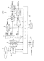
このMPEG方式におけるフレーム間予測の構造を図16(a)に示す。
【0004】
この図16(a)の例においては、1GOP(Group Of Pictures)が15フレームで構成されており、1GOPにおいて、Iピクチャ(Intra Picture)が1フレーム、Pピクチャ(Predictive Picture)が4フレーム、残る10フレームがBピクチャ(Bidirectionally predictive Picture)とされている。なお、GOPは、動画の1シーケンスを分割した符号化の単位である。
【0005】
Iピクチャは、1フレーム内において予測符号化されたフレーム内予測符号化画像であり、Pピクチャは、既に符号化された時間的に前のフレーム(Iピクチャ又はPピクチャ)を参照して予測するフレーム間順方向予測符号化画像であり、Bピクチャは、時間的に前後の2フレームを参照して予測する双方向予測符号化画像である。
【0006】
すなわち、矢印で図示するように、IピクチャI0は、そのフレーム内のみで予測符号化されており、PピクチャP0は、IピクチャI0を参照してフレーム間予測符号化されており、PピクチャP1は、PピクチャP0を参照してフレーム間予測符号化されている。更に、BピクチャB0,B1は、IピクチャI0とPピクチャP0との2つを参照してフレーム間予測符号化されており、BピクチャB2,B3は、PピクチャP0とPピクチャP1との2つを参照してフレーム間予測符号化されている。そして、以下同様に予測符号化されて、以降のピクチャが作成されている。なお、各ピクチャの符号中の添え字は、テンポラル・リファレンス(以下、TRと称する。)を表している。ここで、TRは、GOPの中の画面順を表すものであり、通常の再生時には、このTRの順に各ピクチャが再生される。
【0007】
ところで、このように予測符号化されたピクチャを復号する際、Iピクチャはフレーム内での予測符号化が行われているため、Iピクチャのみで復号することができるが、Pピクチャは時間的に前のIピクチャ又はPピクチャを参照して予測符号化されているため、時間的に前のIピクチャ又はPピクチャが復号時に必要とされ、Bピクチャは時間的に前後のIピクチャ又はPピクチャを参照して予測符号化されているため、時間的に前後のIピクチャ又はPピクチャが復号時に必要とされる。
【0008】
そこで、復号時に必要とされるピクチャを先に復号しておけるように、図16(b)に示すようにピクチャを入れ替えておく。すなわち、BピクチャB-1,B-2は、復号時に先行するGOPのIピクチャ又はPピクチャとIピクチャI0とを必要とするため、BピクチャB-1,B-2よりIピクチャI0が先行するようにしておく。BピクチャB0,B1は、復号時にIピクチャI0とPピクチャP0とを必要とするため、BピクチャB0,B1よりPピクチャP0が先行するようにしておく。BピクチャB2,B3は、復号時にPピクチャP0とPピクチャP1とを必要とするため、BピクチャB2,B3よりPピクチャP1が先行するようにしておく。BピクチャB4,B5は、復号時にPピクチャP1とPピクチャP2とを必要とするため、BピクチャB4,B5よりPピクチャP2が先行するようにしておく。BピクチャB6,B7は、復号時にPピクチャP2とPピクチャP3とを必要とするため、BピクチャB6,B7よりPピクチャP3が先行するようにしておく。
【0009】
このようにMPEG方式によって映像データを圧縮したときには、復号を行う順序(以下、デコーディングオーダーと称する。)と、表示するピクチャの順序(以下、プレゼンテーションオーダーと称する。)とが異なるものとなる。
【0010】
なお、このようなMPEG方式によって圧縮符号化された上でDVDに記録された映像データを再生する映像再生装置では、通常、単なる再生だけでなく、様々なモードが選択できるようになされる。具体的には、例えば、通常再生(以下、Playと称する。)、一時停止(以下、Pauseと称する。)、順方向早送り再生(以下、FFと称する。)、逆方向早送り再生(以下、FRと称する。)、順方向コマ送り再生(以下、StepFと称する。)、逆方向コマ送り再生(以下、StepRと称する。)、順方向低速再生(以下、SlowFと称する。)、逆方向低速再生(以下、SlowRと称する。)等のモードを選択できるようになされる。
【0011】
【発明が解決しようとする課題】
従来、NTSCやPAL方式のテレビジョン信号が記録された記録媒体から動画像を再生する再生装置は、静止画像を表示する場合、フレーム単位での画像表示を行っている。
【0012】
ところが、NTSCやPAL方式のテレビジョン信号は、1フレームが、2つの飛び越し走査により生成したフィールドから構成されている。
【0013】
そのため、フレーム単位での静止画像の表示を行った場合、映画やアニメーションなどの映像ソースに基づき生成されたテレビジョン信号であればフレームを構成する2つのフィールドの画像にブレがなく繊細な画像が得られるが、例えば動きの早い被写体をビデオカメラ等で撮影したような映像ソースから生成されたテレビジョン信号であれば、動きの早い画像のブレが強調されてユーザーにとっては見ずらい画像となってしまう。
【0014】
また、例えば、MPEG2のフォーマットにおいては、圧縮符号化されている情報が、映画やアニメーション等の1秒間に24枚の画面から生成された映像ソースか、或いは、テレビジョン等の1秒間に30枚の画面から生成されている映像ソースかで圧縮されている情報が異なる。しかしながら、従来の再生装置では、どちらの映像ソースであってもフレーム単位の静止画像の表示を行っている。
そして、MPEG方式で圧縮符号化された映像データの再生において、静止画像を表示している状態から動画像の再生に移行するときに、動画像データを表示するタイミングと、復号化のタイミングを正確に合わせることができない場合があった。
【0015】
本発明は、このような実情を鑑みてなされたものであり、インターレース方式の映像データを記録媒体から再生する際に、ユーザーに見やすい静止画像と、記録媒体から符号化された映像データを静止画像の再生から動画像の再生に移行する際に、ユーザに見やすい画像とを提供する記録媒体の再生装置及び記録媒体の再生方法を提供することを目的とする。
【0016】
【課題を解決するための手段】
上述の課題を解決するために、本発明に係る記録媒体の再生装置は、記録媒体から符号化された映像データを復号し、復号された映像データを再生して画像を出力する再生手段と、静止画像再生時において、インターレース方式の映像データが上記記録媒体から再生される場合はフィールド単位の静止画像を上記再生手段から出力させ、ノンインターレース画像の映像データが上記記録媒体から再生される場合はフレーム単位の静止画像を上記再生手段から出力させる制御を行う第1の制御手段と、静止画像再生から動画像再生に移行するとき、復号のタイミング基準となる同期信号の発生時刻が、映像データを分割した各データ単位に含まれる動画像表示開始タイミング情報信号による表示開始時刻に対して映像データの復号が開始されてから画像の表示が開始されるまでの所定遅れ時間前の時刻に達したときに、動画像再生を開始する最初の再生画像の復号を開始させて、静止画像を表示している状態から動画像の再生へ移行させる制御を行う第2の制御手段とを備えることを特徴とする。
【0017】
この記録媒体の再生装置では、制御手段が記録媒体に記録された映像の内容に応じて再生手段を制御し、再生手段からフレーム単位の静止画像とフィールド単位の静止画像を出力する。
【0018】
また、本発明に係る記録媒体の再生装置は、上記制御手段が、インターレース方式の映像データが上記記録媒体から再生される場合はフィールド単位の静止画像を出力し、ノンインターレース方式の映像データが上記記録媒体から再生される場合はフレーム単位の静止画像を出力することを、記録媒体から再生される映像データの管理情報に基づき自動的に切り換えることを特徴とする。
【0019】
この記録媒体の再生装置では、記制御手段が、記録媒体から再生される映像データの管理情報に基づき、フレーム単位の静止画像を出力するかフィールド単位の静止画像を出力するかをに自動的に切り換える。
【0020】
本発明に係る記録媒体の再生方法は、記録媒体から符号化された画像データを復号し、復号された映像データを再生して画像を出力し、静止画像再生時において、インターレース方式の映像データが上記記録媒体から再生される場合はフィールド単位の静止画像を出力させ、ノンインターレース画像の映像データが上記記録媒体から再生される場合はフレーム単位の静止画像を出力させ、静止画像再生から動画像再生に移行するとき、復号のタイミング基準となる同期信号の発生時刻が、映像データを分割した各データ単位に含まれる動画像表示開始タイミング情報信号による表示開始時刻に対して映像データの復号が開始されてから画像の表示が開始されるまでの所定遅れ時間前の時刻に達したときに、動画像再生を開始する最初の再生画像の復号を開始させて、静止画像を表示している状態から動画像の再生へ移行させることを特徴とする。
【0021】
また、本発明に係る記録媒体の再生方法は、インターレース方式の映像データが上記記録媒体から再生される場合はフィールド単位の静止画像を出力し、ノンインターレース方式の映像データが上記記録媒体から再生される場合はフレーム単位の静止画像を出力することを、記録媒体から再生される映像データの管理情報に基づき自動的に切り換えることを特徴とする。
【0022】
【発明の実施の形態】
以下、本発明の実施の形態として、映像等の記録に使用されるDVDであるDVD−Videoに記録された符号化データを復号して映像を再生する映像再生装置に本発明を適用した例について、図面を参照しながら詳細に説明する。
【0023】
まず、図1のブロック構成図を参照して、映像再生装置100の構成について説明する。なお、DVD−Videoでは、映像データ等をMPEG方式により圧縮符号化して、ディスクに記録する。したがって、この映像再生装置100では、MPEG方式により圧縮符号化された上でディスクに記録された映像データ等を読み出して、当該映像データ等を復号して映像を再生する。
【0024】
この映像再生装置100は、記録媒体1からRF信号を再生するピックアップ2と、このピックアップ2により再生されたRF信号が供給され当該RF信号の2値化処理等を行うRF回路3と、RF回路3からの再生データが供給され当該再生データに対してエラー訂正等の復号処理を行うデータデコーダ4と、データデコーダ4により復号処理が施された再生データを主映像圧縮データ、副映像圧縮データ及び音声圧縮データに振り分けるデマルチプレクサ5とを備える。
【0025】
また、この映像再生装置100は、上記主映像圧縮データを伸張するビデオデコーダ6と、上記副映像圧縮データを伸張して主映像データと合成する副映像デコーダ7と、上記音声圧縮データを伸張するオーディオデコーダ8と、ビデオレコーダ6からの主映像データと副映像デコーダ7からの副映像データが合成された映像データが供給され当該映像データをNTSC信号又はPAL信号に変換するデジタル/NTSC,PAL変換回路(以下、単にNTSC変換回路と称する。)9と、オーディオデコーダ8からのオーディオデータが供給され当該オーディオデータをアナログ信号に変換するデジタル/アナログ変換回路(以下、単にD/A変換回路と称する。)10とを備える。
【0026】
また、この映像再生装置100は、ピックアップ2、RF回路3、データデコーダ4、デマルチプレクサ5、ビデオデコーダ6、副映像デコーダ7、オーディオデコーダ8、NTSC変換回路9及びD/A変換回路10を制御するコントローラ11と、このコントローラ11とユーザーの操作入力を媒介するユーザーインターフェース12と、コントローラ11のデータ記憶部となるメモリ13とを備える。
【0027】
記録媒体1は、MPEG方式により圧縮符号化された映像データ等が記録されたDVD−Videoであり、この記録媒体1に記録された映像データ等が映像再生装置100によって再生される。なお、この記録媒体1は、再生専用型、追記型、書換型等のいずれであってもよい。
【0028】
ピックアップ2は、記録媒体1からRF信号を再生して、当該RF信号をRF回路3に供給する。
【0029】
RF回路3は、ピックアップ2から供給されたRF信号に対して、波形等化及び2値化等の処理を施してデジタルデータとその同期信号等を生成する。RF回路3により生成されたデジタルデータ等は、データデコーダ4に供給される。
【0030】
データデコーダ4は、RF回路3により生成されたデジタルデータに基づき、データの復調や誤り訂正等の処理を行う。データデコーダ4により復調及び誤り訂正等の処理が施されたデジタルデータは、デマルチプレクサ5に供給される。また、データデコーダ4では、MPEG方式のフォーマットにおけるシステムヘッダやパックヘッダ等に含まれるパラメータ情報や、後述するナビゲーションパックNV_PCKに含まれる所定の情報等を検出する。この検出したパラメータ情報等は、データデコーダ4からコントローラ11に供給される。
【0031】
また、このデータデコーダ4は、デジタルデータの出力段にトラックバッファ4aを有している。このトラックバッファ4aによりデータデコーダ4とデマルチプレクサ5の処理速度の違いが吸収される。
【0032】
デマルチプレクサ5は、データデコーダ4により復調及び誤り訂正等の処理が施されたデジタルデータを、主映像圧縮データと、副映像圧縮データと、音声圧縮データとに振り分ける。
【0033】
ここで、主映像圧縮データとは、MPEG方式により圧縮された映像データであり、DVDのフォーマットにおけるビデオストリーム(Video streams)に相当する。副映像圧縮データとは、主映像に合成される字幕画像等のデータであり、DVDのフォーマットにおけるサブピクチャストリーム(Sub-picture streams)に相当する。音声圧縮データとは、MPEG等の方式で圧縮された音声データであり、DVDのフォーマットにおけるオーディオストリーム(Audio streams)に相当する。
【0034】
デマルチプレクサ5は、主映像圧縮データをビデオデコーダ6に供給し、副映像圧縮データを副映像デコーダ7に供給し、音声圧縮データをオーディオデコーダ8に供給する。
【0035】
ビデオデコーダ6は、主映像圧縮データの復号処理を行い、この復号処理により伸張された主映像データを生成する。このビデオデコーダ6は、復号処理を行うために3画面分の画像メモリを有している。すなわち、ビデオデコーダ6は、主映像圧縮データを復号することによって得られたピクチャのデータを、不要になったピクチャのデータを順次更新しながら、3画面分まで画像メモリに順次格納していく。そして、ビデオデコーダ6は、復号された各ピクチャを画像メモリから順次読み出して、それらのピクチャのデータを副映像デコーダ7に供給する。
【0036】
なお、ビデオデコーダ6に備えられる画像メモリは、3画面分に限らず、これ以上の画面数分あってもよい。
【0037】
副映像デコーダ7は、副映像圧縮データの復号処理を行い、この復号処理により伸長された副映像データをビデオデコーダ6から供給された主映像データに合成して、主映像と副映像とが合成された映像データを生成する。すなわち、副映像デコーダ7では、字幕画像等の副映像を主映像と合成する。なお、この副映像デコーダ7は、副映像データが無い場合には、主映像データをそのまま映像データとして出力する。副映像デコーダ7によって生成された映像データは、NTSC変換回路9に供給される。
【0038】
オーディオデコーダ8は、音声圧縮データの復号処理を行い、この復号処理により伸張された音声データを生成する。すなわち、オーディオデコーダ8は、音声圧縮データがMPEG方式で圧縮されていれば、MPEG方式に対応した伸張処理を行い、音声データを生成する。なお、音声圧縮データが、MPEG方式のフォーマットではなく、PCM等のフォーマットであれば、そのフォーマットに対応した処理を行う。オーディオデコーダ8によって生成された音声データは、D/A変換回路10に供給される。
【0039】
NTSC変換回路9は、映像データをデジタルデータからNTSCやPAL等のテレビジョン信号に変換して出力する。この出力をCRTディスプレイ等の表示装置に供給することにより、ユーザーが記録媒体1から再生した映像を視聴することができる。
【0040】
D/A変換回路10は、デジタルデータである音声データをアナログの音声データに変換して出力する。この出力をスピーカ等に供給することにより、ユーザーが記録媒体1から再生した音声を視聴することができる。
【0041】
コントローラ11は、ピックアップ2、RF回路3、データデコーダ4、デマルチプレクサ5、ビデオデコーダ6、副映像デコーダ7、オーディオデコーダ8、NTSC変換回路9及びD/A変換回路10の制御を行う。また、コントローラ11には、操作パネルやリモートコントローラ等からなるユーザーインターフェース12を介して、再生モード切換等の操作入力がなされ、この操作入力に基づき各回路の制御を行う。なお、コントローラ11は、メモリ13に各制御に必要なデータ等を記憶させ、メモリ13に記憶させたデータを随時参照して各回路の制御を行う。
【0042】
つぎに、DVD−Videoに記録される符号化データのフォーマットについて、図2及び図3を参照して説明する。
【0043】
DVD−Videoにおいて、符号化データには、主映像データ、副映像データ及び音声データが含まれる。なお、これらの各データは、全てが必須というわけではなく、記録する情報に応じて適宜選択可能であることは言うまでもない。なた、以下の説明では、これらのデータが記録される領域のことを、ビデオゾーンと称する。
【0044】
ビデオゾーンは、図2に示すように、ビデオゾーンの先頭に位置するVMG(Video Manager)と、VMGの後ろに位置するVTS(Video Title Set)とから構成される。VMGは、主にビデオゾーンに含まれているVTSについての情報が記録される領域であり、1つのビデオゾーンに1つ含まれる。一方、VTSは、タイトルが実際に記録される領域であり、1つのビデオゾーンに少なくとも1つは含まれており、最大で99までとされる。なお、DVD−Videoにおいて、タイトルとは、記録されている映像等の一番大きな単位であり、例えば、映画が記録されたDVD−Videoでは、通常、1タイトルが映画1作品に相当する。
【0045】
VMGは、再生に必要な基本的な情報等が記録されるVMGI(VMG Information)と、記録されているデータにアクセスするためのメニュー画面の情報等が記録されるVMGM_VOBS(Video object Set foe VMG Menu)と、VMGIのバックアップであるVMGI_BUP(Backup of the VMGI)とから構成されている。なお、VMGM_VOBSは、必須ではなく、無くても構わない。
【0046】
VTSは、後述するセルの順序や相互の関係等を示すPGCI(Program Chain Information)等が記録されるVTSI(VTS Information)と、記録されているタイトルにアクセスするためのメニュー画面の情報等が記録されるVTSM_VOBS(Video Object Set for the VTS Menu)と、タイトルが実際に記録されるVTSTT_VOBS(Video Object Set for Titles in a VTS)と、VTSIのバックアップであるVTSI_BUP(Backup of the VTSI)とから構成されている。なお、VTSM_VOBSは、必須ではなく、無くても構わない。
【0047】
つぎに、実際に映像のデータが配置されるVOBSについて説明する。なお、ここでは、VMGM_VOBS、VTSM_VOBS及びVTSTT_VOBSをまとめてVOBSと称している。
【0048】
VOBSは、図3に示すように、1以上のVOB(Video object)から構成されており、各VOBは、1以上のCellから構成されている。ここで、各VOBには、各VOBの番号を示すVOB_IDナンバーが割り当てられており、各Cellには、各Cellの番号を示すCell_IDナンバーが割り当てられている。したがって、VOBSの中のCellは、VOB_IDナンバーと、Cell_IDナンバーとによって特定される。そして、これらのCellは、VTSIに記録されているPGCIによって関連付けられている。
【0049】
なお、実際に再生の対象となるCellは、PGCIによって関連付けられたCellの全部とは限らず、一部だけの場合もある。例えば、記録されている映像の一部だけを再生するように予めプログラムして再生を行ういわゆるプログラム再生では、PGCIによって関連付けられたCellのうち、一部のCellだけを再生するようなときがある。このようなとき、再生の対象となるCellは、PGCIによって関連付けられたCellのうちの一部となる。一方、例えば、記録されている映像を最初から最後まで連続して再生するような場合には、PGCIによって関連付けられたCellの全てを再生することとなるので、再生の対象となるCellは、PGCIによって関連付けられたCellの全部となる。
【0050】
そして、Cellは、1以上のVOBU(Video Object Unit)から構成されている。すなわち、DVD−Videoにおいて、映像等のデータは、1以上のGOPを含む所定のデータ単位に予め分割されており、このデータ単位のことをVOBUと称している。なお、デマルチプレクサ5からビデオデコーダ6へのデータの供給は、このVOBUの単位で行われる。
【0051】
VOBUは、1以上のGOP(Group of Pictures)を含むように構成されており、具体的には、図3に示すように、VOBU間の相互の関係等が記録されるナビゲーションパックNV_PCK(Navigation Pack)と、パックヘッダー及び主映像データパケットからなる主映像データパックV_PCK(Video Pack)と、パックヘッダー及び音声データパケットからなる音声データパックA_PCK(Audio Pack)と、パックヘッダー及び副映像データパケットからなる副映像データパックSP_PCK(Sub-Picture Pack)とから構成される。ここで、主映像データパックV_PCKパックは、MPEG2方式についての規格であるISO/IEC13818−2、又はMPEG1方式についての規格であるISO/IEC11172−2に準ずるように圧縮符号化されてなる。
【0052】
上記ナビゲーションパックNV_PCKは、VOBUの先頭に必ず配置される。一方、主映像データパックV_PCK、音声データパックA_PCK及び副映像データパックSP_PCKは、必ずしもVOBUに含まれている必要はない。つぎに、映像再生装置100による符号化データの再生についての具体的な説明に先立って、以下の説明で用いる語句について説明する。
【0053】
本実施の形態では、再生のモードとして、Play、Pause、StepR、SlowR、StepF、SlowF、FF、FRを挙げ、それらのモードを切り換えたときの処理について説明する。そして、このように再生のモードを切り換えたときに、切り換え前のモードにおいて再生されていた最後のピクチャのことを「モード切換前ピクチャ」と称し、切り換え後のモードにおいて最初に表示するピクチャのことを「表示開始ピクチャ」と称する。
【0054】
また、VOBUのスタートアドレスのことを「VOBU_SA」と称する。そして、デマルチプレクサ5からビデオデコーダ6に供給されるVOBUは「エントリーポイント」によって特定される。すなわち、エントリーポイントにVOBU_SAが設定され、当該VOBU_SAが指し示すVOBUが、デマルチプレクサ6からビデオデコーダ6、副映像デコーダ7及びオーディオデコーダ8に供給される。より具体的には、当該VOBUに含まれる主映像データパックV_PCKが、デマルチプレクサ6からビデオデコーダ6に供給されて復号され、当該VOBUに含まれる副映像データパックSP_PCKがデマルチプレクサ6から副映像デコーダ7に供給されて復号され、当該VOBUに含まれる音声データパックA_PCKがデマルチプレクサ6からオーディオデコーダ8に供給され復号される。
【0055】
また、以下の説明では、VOBU_SAのうち、モード切換前ピクチャが含まれるVOBUのVOBU_SAのことを「CURR_VOBU_SA」と称し、モード切換前ピクチャが含まれるVOBUの1つ前のVOBUのVOBU_SAのことを「PREV_VOBU_SA」と称し、モード切換前ピクチャが含まれるVOBUの1つ後のVOBUのVOBU_SAのことを「NEXT_VOBU_SA」と称する。
【0056】
また、VOBUに含まれるピクチャのうちの先頭のピクチャの終了アドレスのことを「VOBU_1STREF_EA」と称する。このVOBU_1STREF_EAは、ナビゲーションパックNV_PCKに記録されている。なお、VOBUにピクチャが含まれていないとき、すなわちVOBUに映像データが含まれていないとき、VOBU_1STREF_EAには0が設定される。
【0057】
また、ナビゲーションパックNV_PCKには、例えば、当該ナビゲーションパックNV_PCKが含まれているVOBUの前後に位置する複数のVOBUのアドレス情報が含まれている。この情報のことを「VOBU_SRI」と称する。また、VOBU_SRIに記録されているアドレス情報のうち、当該VOBUよりの前のビデオストリームを含むVOBUのVOBU_SAのことを「BWDI_Video」と称する。
【0058】
また、各VOBUには、当該VOBUに含まれるピクチャの表示開始のタイミングを示す時刻管理情報が予め記録されている。そして、この時刻管理情報のことを「PTM」と称する。そして、PTMのうち、VOBUに含まれるピクチャの表示を開始すべきタイミングを示すPTMのことを「VOBU_S_PTM」と称し、VOBUに含まれるピクチャの表示が終了するタイミングを示すPTMのことを「VOBU_E_PTM」と称する。すなわち、VOBU_S_PTMは、プレゼンテーションオーダーにおいてVOBUの先頭に位置するピクチャの表示開始のタイミングを示し、VOBU_E_PTMは、プレゼンテーションオーダーにおいてVOBUの最後に位置するピクチャの表示終了のタイミングを示す。
【0059】
また、MPEG方式により圧縮符号化された映像データでは、少なくともGOPの先頭のIピクチャに、復号開始のタイミングを示すDTS(Decoding Time Stamp)が記録されている。そして、映像再生装置100は、映像データの再生時に、復号のタイミングの基準となる同期信号であるSTCを順次進めていき、STCとDTSとを比較して、STCがDTSに達したら、当該DTSが記録されているピクチャの復号を開始するようにする。そして、以下の説明では、DTSのうち、GOPの先頭のIピクチャのDTSのことを「GOP_DTSV」と称する。
【0060】
また、VOBUに含まれるピクチャのデータだけで復号できるピクチャのうち、プレゼンテーションオーダーで最も早く表示されるピクチャのことを「FPP」と称する。また、復号する際に異なるVOBUのピクチャが必要なピクチャのことを「PRE_FPP」と称する。具体的には、PRE_FPPは、一つ前のVOBUの最後のGOPに含まれるピクチャを参照して復号がなされる。したがって、PRE_FPPは、一つ前のVOBUの最後のGOPに含まれるピクチャを復号した後でなければ、復号することができない。なお、MPEG方式において、ピクチャは、当該ピクチャを含むGOPに含まれるピクチャ、又は1つ前のGOPに含まれるピクチャを参照すれば、必ず復号できるように圧縮される。したがって、PRE_FPPは、VOBUの先頭のGOPにだけ存在しうるものであり、VOBUの先頭以外のGOPには存在しない。
【0061】
また、映像再生装置100では、映像データの復号を開始するタイミングと、ピクチャの表示を開始するタイミングには、若干のずれが生じる。そして、以下の説明では、映像データの復号が開始されてからピクチャの表示が開始されるまでの時間のことを「復号遅れDL」と称する。なお、映像表示装置100では、この復号遅れDLが、常に1フィールド分の時間で一定となるようにしている。
つぎに、再生モードが切り換わったときの映像表示装置100の動作について説明する。
【0062】
なお、Play、Pause、SlowF及びStepFでの処理は、全て順方向の再生処理であるので、映像データをデコーディングオーダーにて復号してプレゼンテーションオーダーにて表示するという観点においては、これらのモードでは基本的に同じ処理が行われることとなる。そこで、以下の説明において、これらのモードを区別する必要がないときには、これらのモードをまとめてPlay系モードと称する。なお、FFも順方向の再生処理であるが、FFでは、早送りを行うためにピクチャを飛び飛びで復号することとなるので、復号の順序がPlay、Pause、SlowF及びStepFの場合とは異なるものとなる。したがって、FFは、Play系モードには含めていない。
【0063】
ユーザーインターフェース12を介して再生モードの切り換えを指示する信号がコントローラ11に入力されると、図4乃至図12のフローチャートに示す処理が行われ、切り換え後のモードにおいて最初に復号すべきピクチャが含まれるVOBUがモード切換前ピクチャの情報に基づいて特定された上で、再生モードの切り換えが行われる。以下、この処理について、図4乃至図12のフローチャートを参照して詳細に説明する。
【0064】
再生モードを切り換えるイベントが発生したら、図4に示すように、先ず、ステップS1−1において、コントローラ11は、モード切換前ピクチャの情報を取得する。具体的には、コントローラによって、モード切換前ピクチャのTRと、モード切換前ピクチャが含まれるGOPのGOP_DTSVとを検出して、当該TR及びGOP_DTSVをメモリ13に記憶させるとともに、モード切換前ピクチャがFPPやPRE_FPPであるか否かを判別し、モード切換前ピクチャがFPPやPRE_FPPであるか否かの情報をメモリ13に記憶させる。
【0065】
次に、ステップS1−2において、コントローラ11は、モード切換前ピクチャが含まれるVOBUのナビゲーションパックNV_PCKの情報を検出して、当該ナビゲーションパックNV_PCKの情報をメモリ13に記憶させる。
【0066】
次に、ステップS1−3において、コントローラ11は、切り換え後のモードがPlay系モードであるか否かを判別する。そして、Play系モードならばステップS1−4に進み、Play系モードでないならばステップS1−7に進む。
【0067】
ステップS1−4において、コントローラ11は、ステップS1−1でメモリ13に記憶させた情報に基づいて、モード切換前ピクチャがPRE_FPPであるか否かを判別する。そして、PRE_FPPでないならばステップS1−5へ進み、PRE_FPPであるならばステップS1−6へ進む。
【0068】
ステップS1−5において、コントローラ11は、ステップS1−2でメモリ13に記憶させたナビゲーションパックNV_PCKの情報に基づいて、エントリーポイントをCURR_VOBU_SAに設定する。また、ステップS1−6において、コントローラ11は、ステップS1−2でメモリ13に記憶させたナビゲーションパックNV_PCKの情報に基づいて、エントリーポイントをPREV_VOBU_SAに設定する。
【0069】
すなわち、切り換え後のモードがPlay系モードであり、モード切換前ピクチャがPRE_FPPでないならば、モード切換前ピクチャを含むVOBUを、切り換え後のモードにおいて最初に復号すべきピクチャが含まれるVOBUとして特定する。また、切り換え後のモードがPlay系モードであり、モード切換前ピクチャがPRE_FPPであるならば、モード切換前ピクチャを含むVOBUの前のVOBUを、切り換え後のモードにおいて最初に復号すべきピクチャが含まれるVOBUとして特定する。
【0070】
一方、ステップS1−7において、コントローラ11は、切り換え後のモードがSlowR又はStepRであるか否かを判別する。そして、SlowR又はStepRならばステップS1−8に進み、SlowR又はStepRでないならばステップS1−11に進む。
【0071】
ステップS1−8において、コントローラ11は、ステップS1−1でメモリ13に記憶させた情報に基づいて、モード切換前ピクチャがFPP又はPRE_FPPであるか否かを判別する。そして、FPP又はPRE_FPPでないならばステップS1−9へ進み、FPP又はPRE_FPPであるならばステップS1−10へ進む。
【0072】
ステップS1−9において、コントローラ11は、ステップS1−2でメモリ13に記憶させたナビゲーションパックNV_PCKの情報に基づいて、エントリーポイントをCURR_VOBU_SAに設定する。また、ステップS1−10において、コントローラ11は、ステップS1−2でメモリ13に記憶させたナビゲーションパックNV_PCKの情報に基づいて、エントリーポイントをPREV_VOBU_SAに設定する。
【0073】
すなわち、切り換え後のモードがSlowR又はStepRであり、モード切換前ピクチャがFPPやPRE_FPPでないならば、モード切換前ピクチャを含むVOBUを、切り換え後のモードにおいて最初に復号すべきピクチャが含まれるVOBUとして特定する。また、切り換え後のモードがSlowR又はStepRであり、モード切換前ピクチャがFPP又はPRE_FPPであるならば、モード切換前ピクチャを含むVOBUの前のVOBUを、切り換え後のモードにおいて最初に復号すべきピクチャが含まれるVOBUとして特定する。
【0074】
一方、ステップS1−11において、コントローラ11は、ステップS1−1でメモリ13に記憶させた情報に基づいて、切り換え後のモードがFFであるか否かを判別する。そして、FFであるならばステップS1−12に進み、FFでないならばステップS1−13に進む。なお、ステップS1−13に進むのは、切り換え後のモードが、Play系モード、SlowR、StepR、FFのいずれでもない場合、すなわちFRの場合である。
【0075】
ステップS1−12において、コントローラ11は、ステップS1−2でメモリ13に記憶させたナビゲーションパックNV_PCKの情報に基づいて、エントリーポイントをNEXT_VOBU_SAに設定する。また、ステップS1−13において、コントローラ11は、ステップS1−2でメモリ13に記憶させたナビゲーションパックNV_PCKの情報に基づいて、エントリーポイントをPREV_VOBU_SAに設定する。
【0076】
すなわち、切り換え後のモードがFFのときには、モード切換前ピクチャを含むVOBUの次のVOBUを、切り換え後のモードにおいて最初に復号すべきピクチャが含まれるVOBUとして特定する。また、切り換え後のモードがFRのときには、モード切換前ピクチャを含むVOBUの前のVOBUを、切り換え後のモードにおいて最初に復号すべきピクチャが含まれるVOBUとして特定する。
【0077】
次に、図5のステップS1−20へ進み、コントローラ11は、切り換え前のモードで予めメモリ13に記憶させておいたPGCIの情報に基づいて、エントリーポイントがCellの境界を越えているかを判別する。そして、エントリーポイントがCellの境界を越えているならば、ステップS1−21へ進み、Cellの境界を越えていないならば、図6に示すシーケンスエンドチェックのフローへと進む。なお、エントリーポイントがCellの境界を越えているということは、換言すれば、エントリーポイントがモード切換前ピクチャを含むCellに存在しないということである。
【0078】
ステップS1−21において、コントローラ11は、エントリーポイントがNEXT_VOBU_SAであるか否かを判別する。そして、エントリーポイントがNEXT_VOBU_SAであるならばステップS1−22へ進み、エントリーポイントがNEXT_VOBU_SAでないならばステップ1−24へ進む。ステップS1−22において、コントローラ11は、切り換え前のモードで予めメモリ13に記憶させておいたPGCIの情報に基づいて、モード切換前ピクチャが含まれていたCellが、再生の対象となるCellのうち、最後のCellであるか否かを判別する。そして、最後のCellではないならば、ステップS1−23へ進む。一方、最後のCellであったならば、再生の対象となるCellがなくなったこととなるので、再生処理を終了する。
【0079】
ステップS1−23において、コントローラ11は、エントリーポイントとして設定されているVOBU_SAを、モード切換前ピクチャが含まれていたCellの次のCellの先頭に設定する。すなわち、エントリーポイントを、モード切換前ピクチャが含まれていたCellの次のCellの先頭のVOBUのスタートアドレスに設定する。その後、図6に示すシーケンスエンドチェックのフローへと進む。
【0080】
一方、ステップS1−24において、コントローラ11は、切り換え後のモードがFRであるか否かを判別する。そして、FRであるならばステップS1−25に進み、FRでないならばテップS1−26に進む。
【0081】
ステップS1−25において、コントローラ11は、切り換え前のモードで予めメモリ13に記憶させておいたPGCIの情報に基づいて、モード切換前ピクチャが含まれていたCellが、再生の対象となるCellのうち、先頭のCellであるか否かを判別する。そして、先頭のCellではないならば、ステップS1−27へ進む。一方、先頭のCellであったならば、再生の対象となるCellがなくなったこととなるので、再生処理を終了する。
【0082】
ステップS1−26において、コントローラ11は、切り換え前のモードで予めメモリ13に記憶させておいたPGCIの情報に基づいて、モード切換前ピクチャが含まれていたCellが、PGCIによって関連付けられたCellのうち、先頭のCellであるか否かを判別する。そして、先頭のCellではないならばステップS1−27へ進み、先頭のCellであるならばステップS1−28へ進む。
【0083】
ステップS1−27において、コントローラ11は、エントリーポイントとして設定されているVOBU_SAを、モード切換前ピクチャが含まれていたCellの1つ前のCellの最後のVOBUの先頭に設定する。すなわち、エントリーポイントを、モード切換前ピクチャが含まれていたCellの1つ前のCellの最後のVOBUのスタートアドレスに設定する。その後、図6に示すシーケンスエンドチェックのフローへと進む。
【0084】
ステップS1−28において、コントローラ11は、ステップS1−2でメモリ13に記憶させたナビゲーションパックNV_PCKの情報に基づいて、エントリーポイントをCURR_VOBU_SAに設定する。その後、図6に示すシーケンスエンドチェックのフローへと進む。
【0085】
以上の処理により、再生のモードが切り換わったときに、切り換え後のモードにおいて最初に復号すべきピクチャが含まれるVOBUが特定され、当該VOBUのスタートアドレスがエントリーポイントに設定されることとなる。
【0086】
つぎに、シーケンスエンドチェックの処理の流れについて、図6のフローチャートを参照して説明する。
【0087】
シーケンスエンドチェック処理は、図4及び図5のフローチャートに示した処理によって特定されたVOBUにピクチャが含まれているかをチェックする処理であり、図6に示すように、先ず、ステップS2−1において、コントローラ11は、図4及び図5のフローチャートに示した処理によって設定されたエントリーポイントを、データデコーダ4に供給する。そして、データデコーダ4は、このエントリーポイントが指し示すVOBUをサーチし、当該VOBUをデマルチプレクサ5に供給する。
【0088】
次に、ステップS2−2において、コントローラ11は、ステップS2−1でサーチされたVOBUのナビゲーションパックNV_PCKの情報を検出して、当該ナビゲーションパックNV_PCKの情報をメモリ13に記憶させる。
【0089】
次に、ステップS2−3において、コントローラ11は、ステップS2−1でサーチされたVOBUについて、ステップS2−2でメモリ13に記憶させたナビゲーションパックNV_PCKの情報に基づいて、VOBU_1STREF_EAが0であるか否かを判別する。そして、VOBU_1STREF_EAが0であるならば、当該VOBUにはピクチャが含まれていないということなので、シーケンスエンドを探すために、ステップS2−4に進む。一方、VOBU_1STREF_EAが0でないならば、当該VOBUのデマルチプレクサ5からビデオデコーダ6への供給を開始して、図7に示す再生モード分岐処理のフローへと進む。
【0090】
ステップS2−4において、コントローラ11は、ステップS2−2でメモリ13に記憶させたナビゲーションパックNV_PCKのVOBU_SRIに記録されているBWDI_Videoをデータデコーダ4に供給する。そして、データデコーダ4は、このBWDI_Videoが指し示すVOBUをサーチし、当該VOBUをデマルチプレクサ5に供給する。
【0091】
次に、ステップS2−5において、コントローラ11は、ターゲットにシーケンスエンドコードを設定する。なお、ここで設定されたターゲットは、図8及び図9に示すGoToTarget処理において使用される。
【0092】
次に、ステップS2−6において、図8及び図9に示すGoToTarget処理を行い、その後、ステップS2−7において、コントローラ11は、図4及び図5のフローチャートに示した処理によって設定されたエントリーポイントをデータデコーダ4に供給する。そして、データデコーダ4は、このエントリーポイントが指し示すVOBUをサーチし、当該VOBUをデマルチプレクサ5に供給する。その後、デマルチプレクサ5からビデオデコーダ6へのVOBUの供給を開始して、図7に示す再生モード分岐処理のフローへと進む。
【0093】
つぎに、再生モード分岐処理の流れについて、図7のフローチャートを参照して説明する。
【0094】
再生モード分岐処理では、先ず、ステップS3−1において、コントローラ11は、切り換え後のモードがPlayであるか否かを判別する。そして、Playならばステップ3−2に進み、PlayでないならばステップS3−4に進む。
【0095】
ステップS3−2において、コントローラ11は、ステップS1−1で取得しておいたモード切換前ピクチャの情報に基づいて、ターゲットに表示開始ピクチャを設定する。ここで、表示開始ピクチャの特定は、モード切換前ピクチャのTRと、モード切換前ピクチャが含まれるGOPのGOP_DTSVとに基づいて行う。
【0096】
次に、ステップS3−3において、図8及び図9に示すGoToTarget処理を行う。なお、GoToTarget処理では、ビデオストリームをターゲットまで進めて、当該ターゲットのところから任意のモードでの再生処理が行えるようにする。そして、GoToTarget処理によって、ターゲットとなるピクチャにたどり着いたら、当該ピクチャからplayを開始する。
【0097】
また、ステップS3−4において、コントローラ11は、切り換え後のモードがPauseであるか否かを判別する。そして、Pauseならばステップ3−5に進み、PauseでないならばステップS3−7に進む。
【0098】
ステップS3−5において、コントローラ11は、ステップS1−1で取得しておいたモード切換前ピクチャの情報に基づいて、ターゲットに表示開始ピクチャを設定する。ここで、表示開始ピクチャの特定は、モード切換前ピクチャのTRと、モード切換前ピクチャが含まれるGOPのGOP_DTSVとに基づいて行う。
【0099】
次に、ステップS3−6において、図8及び図9に示すGoToTarget処理を行う。そして、GoToTarget処理によって、ターゲットとなるピクチャにたどり着いたら、当該ピクチャを表示させてPauseする。すなわち、当該ピクチャを表示させてた状態で再生を一時停止する。
【0100】
また、ステップS3−7において、コントローラ11は、切り換え後のモードがStepF又はSlowFであるか否かを判別する。そして、StepF又はSlowFならばステップ3−8に進み、StepF又はSlowFでないならばステップS3−10に進む。
【0101】
ステップS3−8において、コントローラ11は、ステップS1−1で取得しておいたモード切換前ピクチャの情報に基づいて、ターゲットに表示開始ピクチャを設定する。ここで、表示開始ピクチャの特定は、モード切換前ピクチャのTRと、モード切換前ピクチャが含まれるGOPのGOP_DTSVとに基づいて行う。
【0102】
次に、ステップS3−9において、図8及び図9に示すGoToTarget処理を行う。そして、GoToTarget処理によって、ターゲットとなるピクチャにたどり着いたら、当該ピクチャからStepF又はSlowFを開始する。
【0103】
ステップS3−10において、コントローラ11は、切り換え後のモードがStepR又はSlowRであるか否かを判別する。そして、StepR又はSlowRならばステップS3−11に進み、StepR又はSlowRでないならばステップS3−13に進む。
【0104】
ステップS3−11において、コントローラ11は、ステップS1−1で取得しておいたモード切換前ピクチャの情報に基づいて、ターゲットに表示開始ピクチャを設定する。ここで、表示開始ピクチャの特定は、モード切換前ピクチャのTRと、モード切換前ピクチャが含まれるGOPのGOP_DTSVとに基づいて行う。
【0105】
次に、ステップS3−12において、図8及び図9に示すGoToTarget処理を行う。そして、GoToTarget処理によって、ターゲットとなるピクチャにたどり着いたら、当該ピクチャからStepR又はSlowRを開始する。
【0106】
ステップS3−13において、コントローラ11は、切り換え後のモードがFFであるか否かを判別する。そして、切り換え後のモードがFFならば、FFを開始する。一方、切り換え後のモードがFFでないときは、切り換え後のモードがPlay系モード、SlowR、StepR、FFのいずれでもない場合、すなわちFRのときであるので、FRを開始する。なお、切り換え後のモードがFF及びFRのときにGoToTarget処理を行わないのは、FF及びFRでは、常にVOBUの先頭から復号するので、ピクチャ単位でのターゲットの特定が不要だからである。
【0107】
なお、以上のような再生モード分岐処理のステップS3−7乃至S3−9において、StepFとSlowFをまとめて扱っているのは、SlowF及びStepFでの処理はどちらも順方向に1コマずつ再生していく処理であり、映像データをデコーディングオーダーにて復号してプレゼンテーションオーダーにて表示するという観点においては、これらのモードでは基本的に同じ処理が行われるからである。同様に、ステップS3−10乃至S3−12において、StepRとSlowRをまとめて扱っているのは、SlowR及びStepRでの処理はどちらも逆方向に1コマずつ再生していく処理であり、映像データをデコーディングオーダーにて復号してプレゼンテーションオーダーにて表示するという観点においては、これらのモードでは基本的に同じ処理が行われるからである。
【0108】
つぎに、GoToTarget処理の流れについて、図8及び図9のフローチャートを参照して説明する。
【0109】
GoToTarget処理は、基本的には、デマルチプレクサ5からビデオデコーダ6にVOBU単位で供給される映像データに含まれる各ピクチャについて、ターゲットとしているピクチャ(以下、ターゲットピクチャと称する。)であるか否かを、VOBUに含まれるピクチャの先頭から順次、1ピクチャ毎に判別していく処理である。
【0110】
なお、以下の説明において、ターゲットピクチャであるか否かの判別の対象となっているピクチャのことを対象ピクチャと称する。そして、GoToTarget処理を行っているときには、対象ピクチャを1ピクチャ分進める毎に、STCを1ピクチャ分ずつ進めていくようにする。また、GoToTarget処理では、以下に詳細に説明するように、対象ピクチャがターゲットピクチャであるか否かを判別するための情報として、TRとGOP_DTSVを用いる。
【0111】
GoToTarget処理では、先ず、ステップS4−1において、コントローラ11は、ナビゲーションパックNV_PCKが更新されたか否かを判別する。そして、ナビゲーションパックNV_PCKが更新されたならばステップS4−2に進み、ナビゲーションパックNV_PCKが更新されていないならばステップS4−6に進む。なお、ナビゲーションパックNV_PCKは、デマルチプレクサ5からビデオデコーダ6に新しいVOBUが供給され、新しいVOBUに対する処理が開始されたときに更新される。すなわち、ステップS4−1では、デマルチプレクサ5からビデオデコーダ6に新しいVOBUが供給され、新しいVOBUに対する処理が開始されたか否かを判別している。
【0112】
ステップS4−2において、コントローラ11は、ナビゲーションパックNV_PCKの更新回数を記録しておくためのパラメータcountに1を加算する。なお、パラメータcountは、GoToTarget処理に入る前に予め初期化して0にしておく。
【0113】
次に、ステップS4−3において、コントローラ11は、パラメータcountが2以上であるか否かを判別する。そして、2以上であるならばステップS4−4へ進み、2以上でないならばステップS4−6へ進む。なお、パラメータcountは、ナビゲーションパックNV_PCKの更新回数を表している。したがって、このステップS4−3では、デマルチプレクサ5からビデオデコーダ6に、GoToTarget処理において2回以上VOBUが供給されたか否かを判別している。
【0114】
ステップS4−4では、図11に示す1ピクチャ復号処理を行う。なお、1ピクチャ復号処理では、対象ピクチャを復号し、ビデオストリームを次のピクチャのヘッダーまで進める。すなわち、1ピクチャ復号処理では、現在の対象ピクチャを復号した上で、対象ピクチャを次のピクチャへと進める。
【0115】
次に、ステップS4−5において、コントローラ11は、ターゲットピクチャを最後に復号したピクチャとし、その後、図10に示すGoToTarget終了処理へと進む。そして、GoToTarget終了処理において、ターゲットピクチャの表示を行い、その後、GoToTarget処理を終了する。すなわち、所定数以上のVOBUについてターゲットピクチャが含まれているか否かの判別を行っても、ターゲットピクチャが見つからなかったら、最後に復号されていたピクチャを表示して、GoToTarget処理を終了する。
【0116】
一方、ステップS4−6において、コントローラ11は、対象ピクチャが、GOPの先頭のピクチャであるか否かを判別する。そして、GOPの先頭のピクチャであるならばステップS4−7へ進み、GOPの先頭のピクチャでないならば図9のステップS4−9へ進む。
【0117】
ステップS4−7において、コントローラ11は、対象ピクチャが含まれるGOPのGOP_DTSVと、ターゲットピクチャが含まれるGOPのGOP_DTSVであるTgt_GOP_DTSVとを比較する。そして、対象ピクチャが含まれるGOPのGOP_DTSVがTgt_GOP_DTSV以上であるならば、ステップS4−8へ進み、ステップS4−8において、対象ピクチャが含まれるGOPのGOP_DTSVがTgt_GOP_DTSVを過ぎたことを示すフラグpassに1を設定した上で、ステップS4−9へ進む。一方、対象ピクチャが含まれるGOPのGOP_DTSVがTgt_GOP_DTSVよりも小さいならば、ステップS4−8を飛ばしてステップS4−9へ進む。
【0118】
すなわち、対象ピクチャが含まれるGOPのGOP_DTSVが、ターゲットピクチャが含まれるGOPのGOP_DTSVにまで達したならば、ステップS4−8に進んでフラグpassに1を設定した上でステップS4−9へ進み、そうでないならば、ステップS4−8を飛ばしてステップS4−9へ進む。なお、フラグpassは、GoToTarget処理に入る前に予め初期化して0にしておく。
【0119】
ステップS4−9において、コントローラ11は、対象ピクチャがIピクチャ又はPピクチャであるか否かを判別する。そして、Iピクチャ又はPピクチャであるならばステップS4−10へ進み、Iピクチャ又はPピクチャでないならばステップS4−16へ進む。なお、ステップS4−15へ進むのは、対象ピクチャがBピクチャのときである。
【0120】
そして、対象ピクチャがIピクチャ又はPピクチャのときには、先ず、ステップS4−10において、コントローラ11は、ターゲットピクチャを復号したことを示すフラグtgt_decが1であるか否かを判別する。なお、フラグtgt_decは、GoToTarget処理に入る前に予め初期化して0にしておき、後述するようにターゲットピクチャが復号されたときに1を設定する。そして、フラグtgt_decが1であるならばステップS4−11へ進み、フラグtgt_decが1でないならばステップS4−12へ進む。
【0121】
ステップS4−11では、図11に示す1ピクチャ復号処理を行う。その後、図10に示したGoToTarget終了処理を行い、GoToTarget処理を終了する。
【0122】
一方、ステップS4−12において、コントローラ11は、ターゲットがシーケンスエンドコードであるか否かを判別する。そして、ターゲットがシーケンスエンドコードでないならばステップS4−13へ進み、ターゲットがシーケンスエンドコードであるならばステップS4−15へ進む。なお、このときにステップS4−15に進むのは、ステップS2−5においてシーケンスエンドコードがターゲットとして設定されていた場合である。
【0123】
ステップS4−14において、コントローラ11は、フラグpassが1であり、且つ、対象ピクチャのTRがターゲットピクチャのTRに一致しているかを判別する。そして、これらの条件が満たされるならば、ステップS4−14へ進み、ステップS4−14において、フラグtgt_decに1を設定した上で、ステップS4−15へ進む。一方、条件が満たされないときには、ステップS4−14を飛ばして、ステップS4−15へ進む。なお、ステップS4−13において、条件が満たされるのは、対象ピクチャがターゲットピクチャのときである。
【0124】
ステップS4−15では、図11に示す1ピクチャ復号処理を行う。そして、対象ピクチャの復号が完了して、ビデオストリームが次のピクチャのヘッダーまで進められたならば、すなわち対象ピクチャが次のピクチャへと進められたならば、ステップS4−1へ戻って処理を繰り返す。
【0125】
一方、対象ピクチャがBピクチャのときは、先ず、ステップS4−16において、コントローラ11は、ターゲットがシーケンスエンドコードであるか否かを判別する。そして、ターゲットがシーケンスエンドコードでないならばステップS4−17へ進み、ターゲットがシーケンスエンドコードであるならばステップS4−19へ進む。なお、このときにステップS4−19に進むのは、ステップS2−5においてシーケンスエンドコードがターゲットとして設定されていた場合である。
【0126】
ステップS4−17において、コントローラ11は、フラグpassが1であり、且つ、対象ピクチャのTRがターゲットピクチャのTRに一致しているかを判別する。そして、これらの条件が満たされるならば、ステップS4−18へ進み、条件が満たされないときには、ステップS4−19へ進む。なお、ステップS4−17において、条件が満たされるのは、対象ピクチャがターゲットピクチャのときである。
【0127】
ステップS4−18では、図11に示す1ピクチャ復号処理を行う。その後、図10に示したGoToTarget終了処理を行い、GoToTarget処理を終了する。
【0128】
一方、ステップS4−19では、図12に示す1ピクチャスキップ処理を行い、その後、ステップ4−1へ戻って処理を繰り返す。なお、1ピクチャスキップ処理では、対象ピクチャを復号せずに、ビデオストリームを次のピクチャのヘッダーまで進める。すなわち、1ピクチャスキップ処理では、現在の対象ピクチャを復号せずに、対象ピクチャを次のピクチャへと進める。
【0129】
以上のようなGoToTarget処理では、対象ピクチャがIピクチャ又はPピクチャのときには、対象ピクチャがターゲットピクチャであるか否かに関わりなく、対象ピクチャの復号が行われ、一方、対象ピクチャがBピクチャのときには、対象ピクチャがターゲットピクチャである場合にだけ、対象ピクチャの復号が行われる。
【0130】
すなわち、GoToTarget処理では、復号順序に従ってGOPの先頭からピクチャ毎に順次、ターゲットピクチャであるかを判別していき、ターゲットピクチャが見つかったら当該対象ピクチャを復号するとともに、ターゲットピクチャであるかを順次判別していくにあたって、対象ピクチャがIピクチャ又はPピクチャのときには当該対象ピクチャを復号しておくようにする。
【0131】
なお、ターゲットにシーケンスエンドコードが設定されているとき、GoToTarget処理は、以下に説明する1ピクチャ復号処理又は1ピクチャスキップ処理を経て終了する。
【0132】
つぎに、1ピクチャ復号処理の流れについて、図11のフローチャートを参照して説明する。
【0133】
1ピクチャ復号処理では、先ず、ステップS5−1において、ビデオデコーダ6によって対象ピクチャの復号を開始してビデオストリームを進めていく。このとき、ビデオデコーダ6は、ビデオストリームを進めていくことにより、次のピクチャのヘッダーにまで達したら、次のピクチャのヘッダーにまで達したことを示す信号をコントローラ11に送出する。また、ビデオデコーダ6は、ビデオストリームを進めていくことにより、シーケンスエンドコードが検出されたら、シーケンスエンドコードが検出されたことを示す信号をコントローラ11に送出する。
【0134】
ステップS5−2において、コントローラ11は、対象ピクチャの次のピクチャのヘッダーが発見されたか否かを判別する。すなわち、コントローラ11は、ビデオストリームが次のピクチャのヘッダーにまで達したことを示す信号が、ビデオデコーダ6から送出されたかを判別する。そして、次のピクチャのヘッダーが発見されているならば、ステップS5−3へ進み、次のピクチャのヘッダーが発見されていないならば、ステップS5−4へ進む。
【0135】
ここで、ステップS5−3へ進むのは、対象ピクチャの復号が無事に完了し、ビデオストリームが次のピクチャへと進められたときである。そこで、ステップS5−3では、ビデオデコーダ6による復号を止めて、1ピクチャ復号処理を終了する。そして、1ピクチャ復号処理のフローから抜けて、GoToTarget処理へと戻る。
【0136】
一方、ステップS5−4へ進むのは、対象ピクチャの復号が完了していないときである。そして、ステップS5−4において、コントローラ11は、後述する4つの条件が満たされたか否かを判別する。ここで、4つの条件とは、デマルチプレクサ5が停止していること、ビデオデコーダ6に備えられているビデオコードバッファ内のデータが無くなっていること、ビデオデコーダ6にリード割り込みが2フレーム分の時間以上きていないこと、復号がVOBU_E_PTMに至るまで完了していることである。なお、リード割り込みは、例えば、次のピクチャが発見されたときに生じる。そして、これら4つの条件のうちのいずれか1つでも満たされていないならば、ステップS5−5へ進み、これら4つの条件が全て満たされたならば、ステップS5−6へ進む。
【0137】
なお、これら4つの条件が全て満たされるのは、デマルチプレクサ5からビデオデコーダ6への映像データの供給が終了してしまっているときである。そこで、これら4つの条件が全て満たされたときには、ステップS5−6へ進んで、復号が完了しているピクチャのうち、プレゼンテーションオーダーにおいて最後のピクチャをターゲットピクチャとして設定し処理を終了する。
【0138】
ステップS5−5において、コントローラ11は、シーケンスエンドコードが検出されたか否かを判別する。すなわち、コントローラ11は、シーケンスエンドコードが検出されたことを示す信号が、ビデオデコーダ6から送出されたかを判別する。そして、シーケンスエンドコードが検出されているならば、ステップS5−6へ進む。一方、シーケンスエンドコードが検出されていなければ、対象ピクチャの復号が未だ完了していないので、ステップS5−2へ戻って処理を繰り返す。
【0139】
ステップS5−6において、コントローラ11は、復号が完了しているピクチャのうち、プレゼンテーションオーダーにおいて一番最後に位置するピクチャをターゲットピクチャとして設定する。その後、1ピクチャ復号処理のフローから抜けて、GoToTarget終了処理を行う。すなわち、1ピクチャ復号処理において、次のピクチャのヘッダーが見つからなくなったときには、復号が完了しているピクチャのうち、プレゼンテーションオーダーにおける最後のピクチャをターゲットピクチャとして設定して、GoToTarget終了処理へ移行する。
【0140】
つぎに、1ピクチャスキップ処理の流れについて、図12のフローチャートを参照して説明する。
【0141】
1ピクチャスキップ処理では、先ず、ステップS6−1において、ビデオデコーダ6によってビデオストリームを進めていく。このとき、ビデオデコーダ6は、復号せずにビデオストリームを進めていく。なお、上述したように、ビデオデコーダ6は、ビデオストリームを進めていくことにより、次のピクチャのヘッダーにまで達したら、次のピクチャのヘッダーにまで達したことを示す信号をコントローラ11に送出し、ビデオストリームを進めていくことにより、シーケンスエンドコードが検出されたら、シーケンスエンドコードが検出されたことを示す信号をコントローラ11に送出する。
【0142】
ステップS6−2において、コントローラ11は、対象ピクチャの次のピクチャのヘッダーが発見されたか否かを判別する。すなわち、コントローラ11は、ビデオストリームが次のピクチャのヘッダーにまで達したことを示す信号が、ビデオデコーダ6から送出されたかを判別する。そして、次のピクチャのヘッダーが発見されているならば、ステップS6−3へ進み、次のピクチャのヘッダーが発見されていないならば、ステップS6−4へ進む。
【0143】
ここで、ステップS6−3へ進むのは、ビデオストリームが無事に次のピクチャへと進められたときである。そこで、ステップS6−3では、ビデオデコーダ6による処理を止めて、1ピクチャスキップ処理を終了する。そして、1ピクチャスキップ処理のフローから抜けて、GoToTarget処理へと戻る。
【0144】
一方、ステップS6−4へ進むのは、ビデオストリームが次のピクチャへと進められていないときである。そして、ステップS6−4において、コントローラ11は、上述した4つの条件が満たされたか否かを判別する。そして、4つの条件のうちのいずれか1つでも満たされていないならば、ステップS6−5へ進み、4つの条件が全て満たされたならば、ステップS6−6へ進む。
【0145】
なお、4つの条件が全て満たされるのは、デマルチプレクサ5からビデオデコーダ6への映像データの供給が終了してしまっているときである。そこで、4つの条件が全て満たされたときには、ステップS6−6へ進んで、復号が完了しているピクチャのうち、プレゼンテーションオーダーにおいて最後のピクチャをターゲットピクチャとして設定し処理を終了する。
【0146】
ステップS6−5において、コントローラ11は、シーケンスエンドコードが検出されたか否かを判別する。すなわち、コントローラ11は、シーケンスエンドコードが検出されたことを示す信号が、ビデオデコーダ6から送出されたかを判別する。そして、シーケンスエンドコードが検出されているならば、ステップS6−6へ進む。一方、シーケンスエンドコードが検出されていなければ、ビデオストリームが未だ次のピクチャまで進められていないので、ステップS6−2へ戻って処理を繰り返す。
【0147】
ステップS6−6において、コントローラ11は、復号が完了しているピクチャのうち、プレゼンテーションオーダーにおいて一番最後に位置するピクチャをターゲットピクチャとして設定する。その後、1ピクチャスキップ処理のフローから抜けて、GoToTarget終了処理を行う。すなわち、1ピクチャスキップ処理において、次のピクチャのヘッダーが見つからなくなったときには、復号が完了しているピクチャのうち、プレゼンテーションオーダーにおける最後のピクチャをターゲットピクチャとして設定して、GoToTarget終了処理へ移行する。
【0148】
ところで、上述のようなGoToTarget処理を行うときには、主映像のデータを進めて行くだけでなく、他のデータについても処理を進めていく必要がある。すなわち、GoToTarget処理では、映像データが1ピクチャ毎に進められていき、これに合わせてSTCが進められていくが、このとき、副映像データ、音声データ及び字幕データについても、STCに合わせて復号が進められていく。
【0149】
ここで、字幕データはビデオデコーダ6によって復号される。ここで、ビデオデコーダ6は、GoToTarget処理を1ピクチャ分行う毎に進められていくSTCに基づいて、字幕データのDTSに従って、字幕データを復号する。そして、ビデオデコーダ6は、1ピクチャに相当する分の字幕データの復号が完了したら、1ピクチャに相当する分の字幕データの復号が完了したことを示す信号をコントローラ11に送出する。なお、ここで挙げている字幕データとは、主映像データパックV_PCKに付加情報として含まれている字幕のデータのことであり、副映像データではない。
【0150】
また、副映像データは副映像デコーダ7によって復号される。ここで、副映像デコーダ7は、GoToTarget処理を1ピクチャ分行う毎に進められていくSTCに基づいて、副映像データのDTSに従って、副映像データを復号する。そして、副映像デコーダ7は、1ピクチャに相当する分の副映像データの復号が完了したら、1ピクチャに相当する分の副映像データの復号が完了したことを示す信号をコントローラ11に送出する。
【0151】
また、音声データはオーディオデコーダ8によって復号される。ここで、オーディオデコーダ8は、GoToTarget処理を1ピクチャ分行う毎に進められていくSTCに基づいて、音声データのDTSに従って、音声データを復号する。そして、オーディオデコーダ8は、1ピクチャに相当する分の音声データの復号が完了したら、1ピクチャに相当する分の音声データの復号が完了したことを示す信号をコントローラ11に送出する。
【0152】
そして、GoToTarget処理が起動されて、映像データをターゲットピクチャに至るまで進める処理が開始されと、副映像データ、音声データ及び字幕データを復号して、副映像データ、音声データ及び字幕データをターゲットピクチャに相当するところまで進める処理が開始される。以下、この処理について、図13のフローチャートを参照して説明する。なお、図13のフローチャートに示す処理は、GoToTarget処理を1ピクチャ分行う毎に行われる。
【0153】
先ず、ステップS7−1において、コントローラ11は、GoToTarget処理が1ピクチャ分完了したか否かを判別する。すなわち、コントローラ11は、ビデオストリームが次のピクチャのヘッダーにまで達したことを示す信号が、ビデオデコーダ6から送出されたかを判別する。そして、1ピクチャ分の処理が完了していないならば、ステップS7−2へ進み、1ピクチャ分の処理が完了しているならば、ステップS7−8へ進む。
【0154】
ステップS7−2において、コントローラ11は、1ピクチャに相当する分の音声データの復号が完了しているか否かを判別する。すなわち、コントローラ11は、1ピクチャに相当する分の音声データの復号が完了したことを示す信号が、オーディオデコーダ8から送出されたかを判別する。そして、音声データの復号が完了しているならば、ステップS7−3へ進んで更に次の音声データの復号を開始させた後、ステップS7−4へ進む。一方、音声データの復号が完了していないならば、当該音声データの復号処理を継続させたまま、ステップS7−4へ進む。
【0155】
ステップS7−4において、コントローラ11は、1ピクチャに相当する分の副映像データの復号が完了しているか否かを判別する。
【0156】
すなわち、コントローラ11は、1ピクチャに相当する分の副映像データの復号が完了したことを示す信号が、副映像デコーダ7から送出されたかを判別する。そして、副映像データの復号が完了しているならば、ステップS7−5へ進んで更に次の副映像データの復号を開始させた後、ステップS7−6へ進む。一方、副映像データの復号が完了していないならば、当該副映像データの復号処理を継続させたまま、ステップS7−6へ進む。
【0157】
ステップS7−6において、コントローラ11は、1ピクチャに相当する分の字幕データの復号が完了しているか否かを判別する。すなわち、コントローラ11は、1ピクチャに相当する分の字幕データの復号が完了したことを示す信号が、ビデオデコーダ6から送出されたかを判別する。そして、字幕データの復号が完了しているならば、ステップS7−7へ進んで更に次の字幕データの復号を開始させた後、ステップS7−1へ戻って処理を繰り返す。一方、字幕データの復号が完了していないならば、当該字幕データの復号処理を継続させたまま、ステップS7−1へ戻って処理を繰り返す。
【0158】
一方、ステップS7−8において、コントローラ11は、1ピクチャに相当する分の音声データの復号が完了しているか否かを判別する。すなわち、コントローラ11は、1ピクチャに相当する分の音声データの復号が完了したことを示す信号が、オーディオデコーダ8から送出されたかを判別する。そして、音声データの復号が完了しているならば、ステップS7−9へ進み、音声データの復号が完了していないならば、ステップS7−8における判別を当該音声データの復号が完了するまで繰り返す。
【0159】
ステップS7−9において、コントローラ11は、1ピクチャに相当する分の副映像データの復号が完了しているか否かを判別する。すなわち、コントローラ11は、1ピクチャに相当する分の副映像データの復号が完了したことを示す信号が、副映像デコーダ7から送出されたかを判別する。そして、副映像データの復号が完了しているならば、ステップS7−10へ進み、副映像データの復号が完了していないならば、ステップS7−8へ戻って処理を繰り返す。
【0160】
ステップS7−10において、コントローラ11は、1ピクチャに相当する分の字幕データの復号が完了しているか否かを判別する。
【0161】
すなわち、コントローラ11は、1ピクチャに相当する分の字幕データの復号が完了したことを示す信号が、ビデオデコーダ6から送出されたかを判別する。そして、字幕データの復号が完了しているならば、映像データだけでなく、音声データ、副映像データ及び字幕データについても、ターゲットピクチャに相当するところまで復号が進められたこととなるので、処理を終了する。一方、字幕データの復号が完了していないならば、ステップS7−8へ戻って処理を繰り返す。
【0162】
以上のように、GoToTarget処理を1ピクチャ分行う毎に、STCを順次進めていくとともに、当該STCに基づいて、音声データ、副映像データ及び字幕データを順次復号していく。そして、復号された音声データに基づく音声の出力、復号された副映像データに基づく副映像の再生、及び復号された字幕データに基づく字幕の再生は、主映像の再生開始に合わせて開始するようにする。
【0163】
ところで、上述したように、GoToTarget処理を行っているときには、対象ピクチャを1ピクチャ分進める毎に、STCを1ピクチャ分ずつ進めていく。したがって、GoToTarget処理により、ターゲットピクチャが見つかったとき、STCは、再生すべき最初のピクチャであるターゲットピクチャのPTSに達するまで進められた状態となっている。
【0164】
そして、Play以外のモードからPlayに再生モードが切り換わるときに、STCがターゲットピクチャのPTSに達するまで進められた状態のままで再生を開始すると、復号遅れDLの影響により、主映像データ、音声データ、副映像データ及び字幕データの同期が合わなくなることがある。
【0165】
そこで、Play以外のモードからPlayに再生モードが切り換わるときには、再生を開始する前に、STCを復号遅れDLの分以上戻す。具体的には、例えば、再生を開始する前に、3フィールド分だけSTCを戻してやるようにする。その後、再びSTCを進めていき、映像データのDTSに従って映像データの復号を行い、主映像の再生を開始するとともに、音声データ、副映像データ及び字幕データについても、それらのDTSに従って復号を行い、主映像の再生開始に合わせて、音声の出力、副映像の再生及び字幕の再生を開始する。
【0166】
これにより、復号遅れDLの影響を受けることなく、主映像データ、音声データ、副映像データ及び字幕データの同期が正確に合い、主映像の再生と、音声の出力と、副映像の再生と、字幕の再生とが正確に同時に開始されることとなる。ところで、テレビやビデオの画面が1秒あたり30フレームで構成されているのに対して、映画は1秒あたり24コマで構成されている。そこで、DVDでは、映画を収録する場合、1秒あたり24コマとしてディスクに記録された映像データを、再生時に信号処理を行い、1秒あたり30フレームとなるように変換する。すなわち、DVDに記録された1秒あたり24コマのデータをもとに1秒あたり30フレームの映像を再生する際は、最初の2コマから3フレームを作り、次の2コマはそのまま2フレームを作る、という手順を繰り返し行うようにする。これにより、24コマがちょうど30フレーム(60フィールド)となる。なお、このような手法は、一般に2−3プルダウンと呼ばれている。
【0167】
そして、通常、MPEG方式で圧縮符号化された映像データを復号して映像を再生するときは、GOP_DTSVに基づいて復号を開始して映像を再生する。しかしながら、DVDでは、2−3プルダウンを行うため、静止画を表示している状態から動画の再生に移るときに、再生開始のタイミングを正確に合わせることができない場合があった。
【0168】
なお、静止画を表示している状態から動画の再生に移るのは、例えば、PauseからPlayにモードが切り換わるときである。また、Play中であっても、動画と動画の間に静止画が挿入されており、いわゆるビデオギャップが存在しているようなときには、
静止画が表示されている状態から動画の再生に移る場合がある。
【0169】
このように静止画が表示されている状態から動画の再生に移る場合の具体的な例として、図14に示すように、PピクチャP14が静止画として表示されている状態から、動画の再生を開始する場合について考えてみる。ここで、動画の最初のVOBUに含まれているピクチャのうち、デコーディングオーダーにおける最初の3つのピクチャが、IピクチャI2、BピクチャB0、BピクチャB1であり、動画の再生に移るときには、静止画として表示されていたPピクチャP14に続いて、BピクチャB0、BピクチャB1、IピクチャI2を順次表示していくものとする。
【0170】
このとき、PピクチャP14の表示時間が2フィールド分であるならば、動画の再生に移るときには、図14(a)に示すように、GOP_DTSVからIピクチャI 2 の分の時間が経過してから、すなわちGOP_DTSVから2フィールド分の時間が経過してから、BピクチャB0の復号を開始しなければならない。
【0171】
一方、2−3プルダウンが適用されており、PピクチャP14の表示時間が3フィールド分であるならば、動画の再生に移るときには、図14(b)に示すように、GOP_DTSVからIピクチャI 2 の分の時間が経過してから更に1フィールド分の時間が経過してから、すなわちGOP_DTSVから3フィールド分の時間が経過してから、BピクチャB0の復号を開始しなければならない。このように、PピクチャP14の表示時間が3フィールド分であるときには、IピクチャI2の復号が終了した時点から1フィールド分の時間Wだけ待ってから、BピクチャB0の復号を開始しなければならない。
【0172】
このように、BピクチャB0の復号を開始するタイミングは、PピクチャP14の表示時間が2フィールドであるのか、3フィールドであるのかによって、変える必要がある。しかしながら、BピクチャB0を復号するとき、ビデオデコーダ6は、PピクチャP14が何フィールドからなる画像であるかについての情報を持っていない。したがって、GOP_DTSVだけでは、BピクチャB0の復号を開始するタイミングが分からない。
【0173】
そこで、静止画を表示している状態から動画の再生へ移るときには、GOP_DTSVに基づいて復号を開始するのではなく、動画の最初のピクチャを含むVOBUのVOBU_S_PTMを参照し、当該VOBU_S_PTMと復号遅れDLとの差、すなわち(VOBU_S_PTM)−(DL)を求めて、これとSTCを比較するようにする。なお、復号遅れDLは、上述したように、常に1フィールド分の時間で一定である。そして、STCが(VOBU_S_PTM)−(DL)に達したら、すなわち下記式(1)に示す条件が満たされたら、動画の最初のピクチャ(図14の例ではBピクチャB0)の復号を開始する。
【0174】
STC≧(VOBU_S_PTM)−(DL) ・・・(1)
このように、静止画を表示している状態から動画の再生へ移るときに、STCと(VOBU_S_PTM)−(DL)とを比較して、復号を開始するようにすることにより、2−3プルダウンの適用の有無に関わらず、再生開始のタイミングを正確に合わせることが可能となる。
【0175】
なお、静止画を表示している状態から動画の再生へ移るときに、動画の最初のピクチャを含むVOBUにPRE_FPPが含まれている場合には、当該PRE_FPPについては復号を行わないようにしておく。そして、PRE_FPP以外のピクチャ、すなわち復号する際に異なるVOBUのピクチャが不要なピクチャの表示が開始されるまで、静止画を表示した状態で保持しておくようにする。PRE_FPPを表示するためには、前のVOBUの復号から開始しなければならず、煩雑な処理が必要となる。これに対して、上述のように、PRE_FPPを表示しないようにしてしまえば、前のVOBUを復号するような煩雑な処理が不要となる。なお、PRE_FPPは、通常、たかだか2ピクチャ程度であり、再生開始のときにPRE_FPPに表示しなかったとしても、特に問題とはなるようなものではない。
【0176】
ところで、再生モード切換時には、ピクチャがFPPやPRE_FPPであるか否かの判別を行うステップがあるが、ピクチャがFPPやPRE_FPPであるかの判別を行う際には、先ず、ピクチャを含むGOPがVOBUの先頭のGOPであるか否かの判別を行う必要がある。以下に、この判別の方法について説明する。
【0177】
デコーディングオーダーにおいてGOPの先頭のピクチャは必ずIピクチャである。そして、2−3プルダウンが適用され前のピクチャの表示時間が3フィールド分とされていれば、GOPの先頭のIピクチャの復号中に表示されているピクチャの表示時間は、3フィールド分の時間となる。一方、前のピクチャの表示時間が2フィールド分とされていれば、GOPの先頭のIピクチャの復号中に表示されているピクチャの表示時間は、2フィールド分の時間に相当する。
【0178】
そこで、ピクチャを含むGOPがVOBUの先頭のGOPであるか否かの判別を行う際には、VOBU_S_PTMとGOP_DTSVとの差を求め、この値が2乃至3フィールド分の時間に相当しているならば、すなわち下記式(2)及び(3)に示す条件が満たされているならば、当該がVOBUの先頭のGOPであるものと判別する。
【0179】
(2フィールド分の時間)≦(VOBU_S_PTM)−(GOP_DTSV) ・・・(2)
(VOBU_S_PTM)−(GOP_DTSV)≦(3フィールド分の時間) ・・・(3)
そして、ピクチャがFPPやPRE_FPPであるか否かの判別は、以上のようにして、ピクチャを含むGOPがVOBUの先頭のGOPであるか否かの判別した上で行う。
【0180】
つぎに、映像表示装置100の静止画像の表示処理について説明する。
【0181】
映像表示装置100は、上述したようにビデオデコーダ6が映像圧縮データを復号して、このビデオデコーダ6内のメモリに復号した主映像データを格納する。そして、このメモリに格納した主映像データをピクチャの表示タイミングを示すPTMに基づいて出力していく。このとき、NTSC変換回路9から出力される映像信号は、飛び越し走査がされるインターレース画像となることから、ビデオデコーダ6から出力される主映像データもこれに対応したデータとなる。
【0182】
ところで、MPEG2の画像圧縮の方式においては、映像ソースの違いにより圧縮されている1秒あたりのピクチャの枚数が異なり、上述したように再生段階においてフィールドの枚数を調整する2−3プルダウンが行われている。具体的に、映像ソースとしては、映画やアニメーション等の1秒あたり24コマで構成されインターレースがされていないノンインターレースソース、ビデオデータ等の1秒当たり30フレーム(60フィールド)で構成されるインターレースソースがある。
【0183】
記録媒体100に記録された主映像データの映像ソースがインターレースソースであるか又はノンインターレースソースであるかは、MPEG2のフォーマットにおけるピクチャヘッダー(PictureHeader)内のピクチャコーディングエクステンション(Picture Codeing Extention)のプログレッシブフレーム(Progressive_Frame)に示されている。このプログレッシブフレームが0のときは、インターレースソースであることを示しており、プログレッシブフレームが1のときは、ノンインターレースソースであることを示している。
【0184】
映像表示装置100がPauseモードで静止画像を表示する場合は、コントローラ11は、ビデオデコーダ6からこのプログレッシブフレームの情報を検出してフレーム単位で静止画像を表示するフレームポーズと、フィールド単位で静止画像を表示するフィールドポーズの切り換えを行う。また、この切り換えは、ユーザーの操作入力に基づき選択される。このユーザーの操作入力としては、映像ソースを自動的に判別してフレームポーズとフィールドポーズを切り換えるオートモードと、映像ソースに関わらず強制的にフレームポーズを行うフレームモードとがある。すなわち、オートモードでは、コントローラ11がシステムヘッダのプログレッシブフレームの情報を検出して、このプログレッシブフレームが0の場合は1フィールドの静止画像を表示し、1の場合は1フレームつまり2フィールドの静止画像を表示する。
【0185】
ユーザーがフレームモードを選択した場合は、図15(a)及び(b)に示すように、映像ソースがインターレースソースであっても、ノンインターレースモードであっても必ずフレームポーズで静止画像が表示される。
【0186】
また、ユーザーがオートモードを選択した場合であって、映像ソースがノンインタレースソースであれば、図15(a)に示すように、フレームポーズがされる。そして、ユーザーがオートモードを選択した場合であって、映像ソースがインタレースソースであれば、図15(b)に示すように、フィールドポーズがされる。
【0187】
以上のように、映像表示装置100では、記録媒体100に記録された映像ソースに応じてフレーム単位の静止画像とフィールド単位の静止画像を出力することにより、ブレが無く見やすい静止画像をユーザー提供することができる。また、システムヘッダのプログレッシブフレームの情報に基づき、コントローラ11がフレーム単位の静止画像を出力するかフィールド単位の静止画像を出力するかをに自動的に切り換えることにより、ブレがなく見やすい静止画像をユーザーに常に提供することができる。
【0188】
なお、このフレームポーズ及びフィールドポーズは、StepFやStepR等のコマ送り再生において適用しても良い。
【0189】
【発明の効果】
本発明に係る記録媒体の再生装置では、制御手段が記録媒体に記録された映像の内容に応じて再生手段を制御し、静止画像再生時において、再生手段からフレーム単位の静止画像とフィールド単位の静止画像を出力させ、静止画像再生から動画像再生に移行するとき、復号のタイミング基準となる同期信号の発生時刻が、映像データを分割した各データ単位に含まれる動画像表示開始タイミング情報信号による表示開始時刻に対して映像データの復号が開始されてから画像の表示が開始されるまでの所定遅れ時間前の時刻に達したときに、動画像再生を開始する最初の再生画像の復号を開始させて、静止画像を表示している状態から動画像の再生へ移行させることにより、静止画像再生時及び静止画再生時から動画像再生に移行する時にブレが無く見やすい静止画像及び動画像をユーザー提供することができる。
【0190】
また、本発明に係る記録媒体の再生装置では、記録媒体から再生される映像データの管理情報に基づき、フレーム単位の静止画像を出力するかフィールド単位の静止画像を出力するかをに自動的に切り換えることにより、ブレがなく見やすい静止画像をユーザーに常に提供することができる。
【0191】
本発明に係る記録媒体の再生方法では、記録媒体に記録された映像の内容に応じて再生出力を制御し、静止画像再生時において、フレーム単位の静止画像とフィールド単位の静止画像を出力させ、静止画像再生から動画像再生に移行するとき、復号のタイミング基準となる同期信号の発生時刻が、映像データを分割した各データ単位に含まれる動画像表示開始タイミング情報信号による表示開始時刻に対して映像データの復号が開始されてから画像の表示が開始されるまでの所定遅れ時間前の時刻に達したときに、動画像再生を開始する最初の再生画像の復号を開始させて、静止画像を表示している状態から動画像の再生へ移行させることにより、静止画像再生時及び静止画再生時から動画像再生に移行する時にブレが無く見やすい静止画像及び動画像をユーザー提供することができる。
【0192】
また、本発明に係る記録媒体の再生方法では、記録媒体から再生される映像データの管理情報に基づき、フレーム単位の静止画像を出力するかフィールド単位の静止画像を出力するかをに自動的に切り換えることにより、ブレがなく見やすい静止画像をユーザーに常に提供することができる。
【図面の簡単な説明】
【図1】本発明を適用した映像再生装置の一構成例を示すブロック図である。
【図2】DVD−Videoにおけるビデオゾーンのデータフォーマットを示す図である。
【図3】DVD−VideoにおけるVOBSのデータフォーマットを示す図である。
【図4】再生モードが切り換わったときの処理の流れを示すフローチャートである。
【図5】再生モードが切り換わったときの処理の流れを示すフローチャートである。
【図6】シーケンスエンドチェック処理の流れを示すフローチャートである。
【図7】再生モード分岐処理の流れを示すフローチャートである。
【図8】GoToTarget処理の流れを示すフローチャートである。
【図9】GoToTarget処理の流れを示すフローチャートである。
【図10】GoToTarget終了処理の流れを示すフローチャートである。
【図11】1ピクチャ復号処理の流れを示すフローチャートである。
【図12】1ピクチャスキップ処理の流れを示すフローチャートである。
【図13】映像データ、副映像データ、音声データ及び字幕データを復号していくときの処理の流れを示すフローチャートである。
【図14】静止画を表示している状態から動画の再生に移るときの復号開始のタイミングを示す図である。
【図15】映像表示装置100の静止画像の表示画面の説明図である。
【図16】MPEG方式におけるフレーム間予測の構造及び記録フレームの構造を示す図である。
【符号の説明】
100 映像再生装置、 1 記録媒体、 2 ピックアップ、 3 RF回路、 4 データデコーダ、 5 デマルチプレクサ、 6 ビデオデコーダ、7 副映像デコーダ、 8 オーディオデコーダ、 9 NTSC変換回路、10 D/A変換回路、 11 コントローラ、 12 ユーザーインターフェース、 13 メモリ[0001]
BACKGROUND OF THE INVENTION
The present invention relates to a recording medium playback apparatus and a recording medium playback method for displaying moving images and still images.
[0002]
[Prior art]
As a system for compressing and encoding a digital video signal recorded on a digital video disc (hereinafter referred to as DVD), MPEG (Moving Picture Experts Group) method is adopted.
[0003]
FIG. 16A shows the structure of inter-frame prediction in this MPEG system.
[0004]
In the example of FIG. 16A, 1 GOP (Group Of Pictures) is composed of 15 frames. In 1 GOP, 1 frame of I picture (Intra Picture) and 4 frames of P picture (Predictive Picture) remain. Ten frames are set as a B picture (Bidirectionally predictive Picture). Note that GOP is a unit of encoding obtained by dividing one sequence of moving images.
[0005]
An I picture is an intra-frame predictive encoded image that has been predictively encoded within one frame, and a P picture is predicted with reference to an already encoded temporally previous frame (I picture or P picture). It is an inter-frame forward prediction encoded image, and a B picture is a bidirectional predictive encoded image that is predicted with reference to two temporally preceding and subsequent frames.
[0006]
That is, as illustrated by the arrows, I picture I0Is predictively encoded only within that frame, and P picture P0I picture I0And P-picture P1P picture P0The inter-frame prediction encoding is performed with reference to FIG. Furthermore, B picture B0, B1I picture I0And P picture P0, And B picture B2, BThreeP picture P0And P picture P1The inter-frame prediction encoding is performed with reference to the two. Thereafter, predictive encoding is performed in the same manner, and subsequent pictures are created. Note that the subscript in the code of each picture represents a temporal reference (hereinafter referred to as TR). Here, TR represents the screen order in the GOP, and during normal playback, the pictures are played back in this TR order.
[0007]
By the way, when decoding a picture that has been predictively encoded in this way, an I picture is subjected to predictive encoding within a frame, so that it can be decoded only with an I picture, but a P picture is temporally Since predictive coding is performed with reference to the previous I picture or P picture, the temporally previous I picture or P picture is required at the time of decoding, and the B picture includes temporally preceding and following I pictures or P pictures. Since prediction encoding is performed with reference, temporally preceding and following I pictures or P pictures are required at the time of decoding.
[0008]
Therefore, the pictures are replaced as shown in FIG. 16B so that the pictures required for decoding can be decoded first. That is, B picture B-1, B-2Is the I picture or P picture and I picture I of the preceding GOP at the time of decoding0B picture B-1, B-2I picture I0To be preceded. B picture B0, B1I picture I0And P picture P0B picture B0, B1P picture P0To be preceded. B picture B2, BThreeP picture P at the time of decoding0And P picture P1B picture B2, BThreeP picture P1To be preceded. B picture BFour, BFiveP picture P at the time of decoding1And P picture P2B picture BFour, BFiveP picture P2To be preceded. B picture B6, B7P picture P at the time of decoding2And P picture PThreeB picture B6, B7P picture PThreeTo be preceded.
[0009]
Thus, when video data is compressed by the MPEG method, the decoding order (hereinafter referred to as a decoding order) differs from the order of pictures to be displayed (hereinafter referred to as a presentation order).
[0010]
In addition, such MPEG systemInTherefore, in a video playback apparatus that plays back video data recorded on a DVD after being compressed and encoded, various modes can usually be selected in addition to simple playback. Specifically, for example, normal playback (hereinafter referred to as Play), pause (hereinafter referred to as Pause), forward fast forward playback (hereinafter referred to as FF), reverse fast forward playback (hereinafter referred to as FR). ), Forward frame-by-frame playback (hereinafter referred to as StepF), reverse frame-by-frame playback (hereinafter referred to as StepR), forward low-speed playback (hereinafter referred to as SlowF), and reverse low-speed playback. A mode such as (hereinafter referred to as SlowR) can be selected.
[0011]
[Problems to be solved by the invention]
2. Description of the Related Art Conventionally, a reproducing apparatus that reproduces a moving image from a recording medium on which an NTSC or PAL television signal is recorded displays an image in units of frames when displaying a still image.
[0012]
However, NTSC and PAL television signals are composed of fields generated by two interlaced scans in one frame.
[0013]
Therefore, when a still image is displayed in units of frames, if the television signal is generated based on a video source such as a movie or an animation, the images of the two fields constituting the frame are not blurred and have a delicate image. For example, a television signal generated from a video source such as a fast-moving subject shot with a video camera or the like emphasizes blurring of fast-moving images and makes it difficult for users to see. End up.
[0014]
For example, in the MPEG2 format, compression is used.CodingInformation is compressed with a video source generated from 24 screens per second such as movies and animations, or a video source generated from 30 screens per second such as television. Different information. However, the conventional playback apparatus displays still images in units of frames regardless of the video source.
When reproducing video data compressed and encoded by the MPEG method, when moving from still image display to moving image reproduction, the timing for displaying moving image data and the timing for decoding are accurate. There was a case that it was not possible to match.
[0015]
The present invention has been made in view of such circumstances, and a still image that is easy for a user to view when reproducing interlaced video data from a recording medium.And images that are easy for the user to view when moving video data encoded from a recording medium from playback of still images to playback of moving imagesAn object of the present invention is to provide a recording medium reproducing apparatus and a recording medium reproducing method.
[0016]
[Means for Solving the Problems]
In order to solve the above-described problem, a recording medium reproducing apparatus according to the present invention includes a reproducing unit that decodes video data encoded from a recording medium, reproduces the decoded video data, and outputs an image; When interlace video data is played back from the recording medium at the time of still image playback, a field-by-field still image is output from the playback means, and non-interlaced video data is played back from the recording medium. First control means for performing control to output a still image in frame units from the reproduction means;When moving from still image playback to video playbackThe generation time of the synchronization signal that is the timing reference for decoding isDisplay start time by moving image display start timing information signal included in each data unit obtained by dividing video dataWhen the time before a predetermined delay time from the start of video data decoding to the start of image display is reached, decoding of the first playback image to start moving image playback is started, And a second control means for performing control for shifting from a state in which a still image is displayed to reproduction of a moving image.
[0017]
In this recording medium playback apparatus, the control means controls the playback means in accordance with the content of the video recorded on the recording medium, and outputs a still image in frame units and a still image in field units from the playback means.
[0018]
In the recording medium reproducing apparatus according to the present invention, the control means outputs a still image in field units when the interlaced video data is reproduced from the recording medium, and the non-interlaced video data is When reproducing from a recording medium, outputting a still image in units of frames is automatically switched based on management information of video data reproduced from the recording medium.
[0019]
In this recording medium playback apparatus, the recording control unit automatically determines whether to output a still image in frame units or a still image in field units based on management information of video data reproduced from the recording medium. Switch.
[0020]
The recording medium reproduction method according to the present invention decodes image data encoded from a recording medium, reproduces the decoded video data, and outputs an image. When reproducing a still image, interlaced video data is reproduced. When reproduced from the recording medium, a still image in a field unit is output.When video data of a non-interlaced image is reproduced from the recording medium, a still image in a frame unit is output.When moving from still image playback to video playbackThe generation time of the synchronization signal that is the timing reference for decoding isVideo display start timing information signal included in each data unit obtained by dividing video dataWhen the time reaches a time before a predetermined delay time from the start of video data decoding to the start of image display with respect to the display start time by It is characterized by starting and shifting from a state in which a still image is displayed to reproduction of a moving image.
[0021]
The recording medium reproduction method according to the present invention outputs a still image in field units when interlaced video data is reproduced from the recording medium, and non-interlaced video data is reproduced from the recording medium. In this case, output of a still image in units of frames is automatically switched based on management information of video data reproduced from a recording medium.
[0022]
DETAILED DESCRIPTION OF THE INVENTION
Hereinafter, as an embodiment of the present invention, an example in which the present invention is applied to a video playback apparatus that decodes encoded data recorded on DVD-Video, which is a DVD used for recording video, etc., and plays back the video. This will be described in detail with reference to the drawings.
[0023]
First, the configuration of the
[0024]
The
[0025]
The
[0026]
The
[0027]
The
[0028]
The
[0029]
The
[0030]
The
[0031]
The
[0032]
The demultiplexer 5 distributes the digital data that has been demodulated and error corrected by the
[0033]
Here, the main video compressed data is video data compressed by the MPEG system, and corresponds to a video stream in the DVD format. The sub-picture compressed data is data such as a caption image synthesized with the main picture, and corresponds to a sub-picture stream in the DVD format. The audio compression data is audio data compressed by a method such as MPEG, and corresponds to an audio stream in the DVD format.
[0034]
The demultiplexer 5 supplies the main video compressed data to the
[0035]
The
[0036]
Note that the image memory provided in the
[0037]
The sub-picture decoder 7 decodes the sub-picture compressed data, synthesizes the sub-picture data expanded by this decoding process with the main picture data supplied from the
[0038]
The
[0039]
The NTSC conversion circuit 9 converts the video data from digital data into a television signal such as NTSC or PAL and outputs it. By supplying this output to a display device such as a CRT display, the user can view the video reproduced from the
[0040]
The D / A conversion circuit 10 converts audio data that is digital data into analog audio data and outputs the analog audio data. By supplying this output to a speaker or the like, it is possible to view the audio reproduced from the
[0041]
The
[0042]
Next, the format of encoded data recorded on the DVD-Video will be described with reference to FIGS.
[0043]
In DVD-Video, encoded data includes main video data, sub-video data, and audio data. It is needless to say that all of these data is not essential, and can be appropriately selected according to the information to be recorded. In the following description, an area in which these data are recorded is referred to as a video zone.
[0044]
As shown in FIG. 2, the video zone includes a VMG (Video Manager) positioned at the beginning of the video zone and a VTS (Video Title Set) positioned after the VMG. The VMG is an area in which information about VTSs mainly included in the video zone is recorded, and one VMG is included in one video zone. On the other hand, the VTS is an area where a title is actually recorded, and at least one is included in one video zone, and the maximum is 99. In DVD-Video, a title is the largest unit of recorded video or the like. For example, in a DVD-Video on which a movie is recorded, one title usually corresponds to one movie.
[0045]
The VMG is a VMGI (VMG Information) in which basic information necessary for reproduction is recorded, and a VMGM_VOBS (Video object Set foe VMG Menu) in which information on a menu screen for accessing recorded data is recorded. ) And VMGI_BUP (Backup of the VMGI) which is a backup of VMGI. Note that VMGM_VOBS is not essential and may be omitted.
[0046]
The VTS records VTSI (VTS Information) in which PGCI (Program Chain Information) indicating the order of cells and mutual relations described later is recorded, and information on a menu screen for accessing the recorded title. VTSM_VOBS (Video Object Set for the VTS Menu), VTSTT_VOBS (Video Object Set for Titles in a VTS) where the title is actually recorded, and VTSI_BUP (Backup of the VTSI) which is a backup of VTSI. ing. Note that VTSM_VOBS is not essential and may be omitted.
[0047]
Next, VOBS in which video data is actually arranged will be described. Here, VMGM_VOBS, VTSM_VOBS, and VTSTT_VOBS are collectively referred to as VOBS.
[0048]
As shown in FIG. 3, the VOBS is composed of one or more VOBs (Video objects), and each VOB is composed of one or more Cells. Here, each VOB is assigned a VOB_ID number indicating the number of each VOB, and each Cell is assigned a Cell_ID number indicating the number of each Cell. Therefore, the Cell in the VOBS is specified by the VOB_ID number and the Cell_ID number. These cells are associated by PGCI recorded in VTSI.
[0049]
Note that the cells that are actually to be reproduced are not necessarily all of the cells associated by PGCI, but may be only a part of the cells. For example, in the so-called program playback in which playback is performed by programming in advance so as to play back only a part of the recorded video, only some of the cells associated with the PGCI are played back. . In such a case, the cell to be reproduced is a part of the cells associated by PGCI. On the other hand, for example, when the recorded video is played back continuously from the beginning to the end, all of the cells associated by the PGCI are played back, so that the cell to be played back is the PGCI. It becomes all of the Cell related by.
[0050]
The Cell is composed of one or more VOBUs (Video Object Units). That is, in DVD-Video, data such as video is divided in advance into predetermined data units including one or more GOPs, and this data unit is referred to as VOBU. Note that data is supplied from the demultiplexer 5 to the
[0051]
The VOBU is configured to include one or more GOPs (Group of Pictures). Specifically, as shown in FIG. 3, a navigation pack NV_PCK (Navigation Pack) in which a mutual relationship between VOBUs is recorded. ), A main video data pack V_PCK (Video Pack) composed of a pack header and a main video data packet, an audio data pack A_PCK (Audio Pack) composed of a pack header and an audio data packet, and a pack header and a sub video data packet. It is composed of a sub-picture data pack SP_PCK (Sub-Picture Pack). Here, the main video data pack V_PCK pack is compression-encoded so as to conform to ISO / IEC13818-2 which is a standard for the MPEG2 system or ISO / IEC11172-2 which is a standard for the MPEG1 system.
[0052]
The navigation pack NV_PCK is always arranged at the head of the VOBU. On the other hand, the main video data pack V_PCK, the audio data pack A_PCK, and the sub video data pack SP_PCK are not necessarily included in the VOBU. Next, prior to specific description of reproduction of encoded data by the
[0053]
In the present embodiment, Play, Pause, StepR, SlowR, StepF, SlowF, FF, and FR are listed as playback modes, and processing when these modes are switched will be described. When the playback mode is switched in this way, the last picture played back in the mode before switching is referred to as “pre-mode switching picture” and is the picture that is displayed first in the mode after switching. Is referred to as a “display start picture”.
[0054]
The start address of VOBU is referred to as “VOBU_SA”. The VOBU supplied from the demultiplexer 5 to the
[0055]
In the following description, VOBU_SA of a VOBU that includes a picture before mode switching is referred to as “CURR_VOBU_SA” in VOBU_SA, and VOBU_SA of the VOBU immediately before the VOBU that includes a picture before mode switching is “ It is referred to as “PREV_VOBU_SA”, and the VOBU_SA of the VOBU immediately after the VOBU including the pre-mode switching picture is referred to as “NEXT_VOBU_SA”.
[0056]
Further, the end address of the first picture among the pictures included in the VOBU is referred to as “VOBU_1STREF_EA”. This VOBU_1STREF_EA is recorded in the navigation pack NV_PCK. When no picture is included in VOBU, that is, when video data is not included in VOBU, 0 is set in VOBU_1STREF_EA.
[0057]
In addition, the navigation pack NV_PCK includes, for example, address information of a plurality of VOBUs positioned before and after the VOBU in which the navigation pack NV_PCK is included. This information is referred to as “VOBU_SRI”. Of the address information recorded in the VOBU_SRI, the VOBU_SA of the VOBU including the video stream before the VOBU is referred to as “BWDI_Video”.
[0058]
In addition, each VOBUTime management information indicating the display start timing of the picture included in the VOBUIs recorded in advance. The time management information is referred to as “PTM”. Of the PTMs, the PTM indicating the timing at which the display of the picture included in the VOBU should start is referred to as “VOBU_S_PTM”, and the PTM indicating the timing at which the display of the picture included in the VOBU ends is “VOBU_E_PTM”. Called. That is, VOBU_S_PTM indicates the display start timing of the picture positioned at the head of the VOBU in the presentation order, and VOBU_E_PTM indicates the display end timing of the picture positioned at the end of the VOBU in the presentation order.
[0059]
Further, in video data compression-encoded by the MPEG method, a DTS (Decoding Time Stamp) indicating a decoding start timing is recorded at least in the first I picture of the GOP. Then, the
[0060]
Of pictures that can be decoded only with picture data included in the VOBU, a picture that is displayed earliest in the presentation order is referred to as “FPP”. A picture that requires a different VOBU picture when decoding is referred to as “PRE_FPP”. Specifically, PRE_FPP is decoded with reference to a picture included in the last GOP of the previous VOBU. Therefore, PRE_FPP can be decoded only after decoding the picture included in the last GOP of the previous VOBU. In the MPEG system, a picture is compressed such that it can be decoded by referring to a picture included in a GOP including the picture or a picture included in a previous GOP. Therefore, PRE_FPP can exist only in the first GOP of the VOBU, and does not exist in the GOP other than the first VOBU.
[0061]
Further, in the
Next, the operation of the
[0062]
Note that Play, Pause, Slow F, and Step F are all forward playback processes, so from the viewpoint of decoding video data in decoding order and displaying it in presentation order, Basically, the same processing is performed. Therefore, in the following description, when it is not necessary to distinguish between these modes, these modes are collectively referred to as “Play mode”. Note that FF is also a forward playback process, but in FF, pictures are skipped for fast-forwarding, so that the decoding order is different from that for Play, Pause, SlowF, and StepF. Become. Therefore, FF is not included in the Play system mode.
[0063]
When a signal instructing switching of the playback mode is input to the
[0064]
When an event for switching the playback mode occurs, as shown in FIG. 4, first, in step S1-1, the
[0065]
Next, in step S1-2, the
[0066]
Next, in step S1-3, the
[0067]
In step S1-4, the
[0068]
In step S1-5, the
[0069]
That is, if the mode after switching is the Play system mode and the picture before mode switching is not PRE_FPP, the VOBU including the picture before mode switching is specified as the VOBU including the picture to be decoded first in the mode after switching. . If the mode after switching is the Play system mode and the picture before mode switching is PRE_FPP, the VOBU before the VOBU including the picture before mode switching includes the picture to be decoded first in the mode after switching. VOBU specified.
[0070]
On the other hand, in step S1-7, the
[0071]
In step S1-8, the
[0072]
In step S1-9, the
[0073]
That is, if the mode after switching is SlowR or StepR and the picture before mode switching is not FPP or PRE_FPP, the VOBU including the picture before mode switching is set as the VOBU including the picture to be decoded first in the mode after switching. Identify. If the mode after switching is SlowR or StepR and the picture before mode switching is FPP or PRE_FPP, the VOBU before the VOBU including the picture before mode switching is the first picture to be decoded in the mode after switching. Is specified as a VOBU including
[0074]
On the other hand, in step S1-11, the
[0075]
In step S1-12, the
[0076]
That is, when the mode after switching is FF, the VOBU next to the VOBU including the picture before mode switching is specified as the VOBU including the picture to be decoded first in the mode after switching. The mode after switching isFRIn this case, the VOBU before the VOBU including the picture before mode switching is specified as the VOBU including the picture to be decoded first in the mode after switching.
[0077]
Next, the process proceeds to step S1-20 in FIG. 5, and the
[0078]
In step S1-21, the
[0079]
In step S1-23, the
[0080]
On the other hand, in step S1-24, the
[0081]
In step S1-25, based on the PGCI information stored in the memory 13 in advance in the mode before switching, the
[0082]
In step S1-26, the
[0083]
In step S1-27, the
[0084]
In step S1-28, the
[0085]
With the above processing, when the playback mode is switched, the VOBU including the picture to be decoded first is specified in the switched mode, and the start address of the VOBU is set as the entry point.
[0086]
Next, the flow of the sequence end check process will be described with reference to the flowchart of FIG.
[0087]
The sequence end check process is a process for checking whether or not a picture is included in the VOBU specified by the processes shown in the flowcharts of FIGS. 4 and 5. As shown in FIG. 6, first, in step S 2-1. The
[0088]
Next, in step S2-2, the
[0089]
Next, in step S2-3, the
[0090]
In step S2-4, the
[0091]
Next, in step S2-5, the
[0092]
Next, in step S2-6, GoToTarget processing shown in FIG. 8 and FIG. 9 is performed. Thereafter, in step S2-7, the
[0093]
Next, the flow of the reproduction mode branching process will be described with reference to the flowchart of FIG.
[0094]
In the reproduction mode branch process, first, in step S3-1, the
[0095]
In step S <b> 3-2, the
[0096]
Next, in step S3-3, GoToTarget processing shown in FIGS. 8 and 9 is performed. In the GoToTarget process, the video stream is advanced to the target, and the reproduction process in an arbitrary mode can be performed from the target. When the target picture is reached by the GoToTarget process, play is started from the picture.
[0097]
In step S3-4, the
[0098]
In step S3-5, the
[0099]
Next, in step S3-6, GoToTarget processing shown in FIGS. 8 and 9 is performed. When the target picture is reached by the GoToTarget process, the picture is displayed and paused. That is, playback is paused while the picture is displayed.
[0100]
In step S3-7, the
[0101]
In step S3-8, the
[0102]
Next, in step S3-9, GoToTarget processing shown in FIGS. 8 and 9 is performed. Then, when the target picture is reached by GoToTarget processing, StepF or SlowF is started from the picture.
[0103]
In step S3-10, the
[0104]
In step S3-11, the
[0105]
Next, in step S3-12, GoToTarget processing shown in FIGS. 8 and 9 is performed. Then, when the target picture is reached by GoToTarget processing, StepR or SlowR is started from the picture.
[0106]
In step S3-13, the
[0107]
In Steps S3-7 to S3-9 of the playback mode branching process as described above, StepF and SlowF are handled together. Both the processes in SlowF and StepF play back one frame at a time in the forward direction. This is because the same processing is basically performed in these modes from the viewpoint of decoding the video data with the decoding order and displaying it with the presentation order. Similarly, in Steps S3-10 to S3-12, StepR and SlowR are handled together as the processing in SlowR and StepR is a process of playing back one frame at a time in the reverse direction. This is because, basically, the same processing is performed in these modes from the viewpoint of decoding in the decoding order and displaying in the presentation order.
[0108]
Next, the flow of GoToTarget processing will be described with reference to the flowcharts of FIGS.
[0109]
In the GoToTarget process, basically, each picture included in the video data supplied from the demultiplexer 5 to the
[0110]
In the following description, a picture that is a target for determining whether or not it is a target picture is referred to as a target picture. When the GoToTarget process is performed, the STC is advanced by one picture every time the target picture is advanced by one picture. In the GoToTarget process, TR and GOP_DTSV are used as information for determining whether or not the target picture is a target picture, as will be described in detail below.
[0111]
In the GoToTarget process, first, in step S4-1, the
[0112]
In step S4-2, the
[0113]
Next, in step S4-3, the
[0114]
In step S4-4, the one-picture decoding process shown in FIG. 11 is performed. In the one-picture decoding process, the target picture is decoded and the video stream is advanced to the header of the next picture. That is, in the one-picture decoding process, the current target picture is decoded and the target picture is advanced to the next picture.
[0115]
Next, in step S4-5, the
[0116]
On the other hand, in step S4-6, the
[0117]
In step S4-7, the
[0118]
That is, when the GOP_DTSV of the GOP including the target picture reaches the GOP_DTSV of the GOP including the target picture, the process proceeds to step S4-8, the flag pass is set to 1, and the process proceeds to step S4-9. Otherwise, skip step S4-8 and proceed to step S4-9. The flag pass is initialized and set to 0 before entering the GoToTarget process.
[0119]
In step S4-9, the
[0120]
When the target picture is an I picture or a P picture, first, in step S4-10, the
[0121]
In step S4-11, the one-picture decoding process shown in FIG. 11 is performed. Thereafter, the GoToTarget end process shown in FIG. 10 is performed, and the GoToTarget process ends.
[0122]
On the other hand, in step S4-12, the
[0123]
In step S4-14, the
[0124]
In step S4-15, the one-picture decoding process shown in FIG. 11 is performed. If decoding of the target picture is completed and the video stream is advanced to the header of the next picture, that is, if the target picture is advanced to the next picture, the process returns to step S4-1 to perform the processing. repeat.
[0125]
On the other hand, when the target picture is a B picture, first, in step S4-16, the
[0126]
In step S4-17, the
[0127]
In step S4-18, the one-picture decoding process shown in FIG. 11 is performed. Thereafter, the GoToTarget end process shown in FIG. 10 is performed, and the GoToTarget process ends.
[0128]
On the other hand, in step S4-19, the one-picture skip process shown in FIG. 12 is performed, and then the process returns to step 4-1 to repeat the process. In the one-picture skip process, the video stream is advanced to the header of the next picture without decoding the target picture. That is, in the one-picture skip process, the current picture is not decoded and the current picture is advanced to the next picture.
[0129]
In the GoToTarget processing as described above, when the target picture is an I picture or P picture, the target picture is decoded regardless of whether the target picture is a target picture or not. On the other hand, when the target picture is a B picture, Only when the target picture is the target picture, the target picture is decoded.
[0130]
That is, in the GoToTarget process, it is determined for each picture sequentially from the beginning of the GOP according to the decoding order, and when the target picture is found, the target picture is decoded and the target picture is sequentially determined. In doing so, when the target picture is an I picture or a P picture, the target picture is decoded.
[0131]
Note that when a sequence end code is set for the target, the GoToTarget process ends after a one-picture decoding process or a one-picture skip process described below.
[0132]
Next, the flow of 1-picture decoding processing will be described with reference to the flowchart of FIG.
[0133]
In the one-picture decoding process, first, in step S5-1, the
[0134]
In step S5-2, the
[0135]
Here, the process proceeds to step S5-3 when the decoding of the target picture is successfully completed and the video stream is advanced to the next picture. Therefore, in step S5-3, the decoding by the
[0136]
On the other hand, the process proceeds to step S5-4 when the target picture has not been decoded. In step S5-4, the
[0137]
Note that all these four conditions are satisfied when the supply of video data from the demultiplexer 5 to the
[0138]
In step S5-5, the
[0139]
In step S5-6, the
[0140]
Next, the flow of one-picture skip processing will be described with reference to the flowchart of FIG.
[0141]
In the one-picture skip process, first, in step S6-1, the video stream is advanced by the
[0142]
In step S6-2, the
[0143]
Here, the process proceeds to step S6-3 when the video stream is safely advanced to the next picture. Therefore, in step S6-3, the process by the
[0144]
On the other hand, the process proceeds to step S6-4 when the video stream is not advanced to the next picture. In step S6-4, the
[0145]
Note that all four conditions are satisfied when the supply of video data from the demultiplexer 5 to the
[0146]
In step S6-5, the
[0147]
In step S6-6, the
[0148]
By the way, when performing the GoToTarget process as described above, it is necessary not only to advance the data of the main video but also to process the other data. That is, in GoToTarget processing, video data is advanced for each picture, and STC is advanced accordingly. At this time, sub-video data, audio data, and subtitle data are also decoded in accordance with STC. Will be promoted.
[0149]
Here, the caption data is decoded by the
[0150]
The sub video data is decoded by the sub video decoder 7. Here, the sub-picture decoder 7 decodes the sub-picture data according to the DTS of the sub-picture data based on the STC that is advanced every time GoToTarget processing is performed for one picture. Then, when the decoding of the sub-picture data corresponding to one picture is completed, the sub-picture decoder 7 sends a signal indicating that the decoding of the sub-picture data corresponding to one picture is completed to the
[0151]
The audio data is decoded by the
[0152]
When the GoToTarget process is started and the process of advancing the video data to the target picture is started, the sub-video data, audio data, and subtitle data are decoded, and the sub-video data, audio data, and subtitle data are converted to the target picture. The process of proceeding to the place corresponding to is started. Hereinafter, this process will be described with reference to the flowchart of FIG. The process shown in the flowchart of FIG. 13 is performed every time the GoToTarget process is performed for one picture.
[0153]
First, in step S7-1, the
[0154]
In step S7-2, the
[0155]
In step S7-4, the
[0156]
That is, the
[0157]
In step S7-6, the
[0158]
On the other hand, in step S7-8, the
[0159]
In step S7-9, the
[0160]
In step S7-10, the
[0161]
That is, the
[0162]
As described above, every time GoToTarget processing is performed for one picture, STC is sequentially advanced, and audio data, sub-picture data, and caption data are sequentially decoded based on the STC. Then, audio output based on the decoded audio data, reproduction of the sub-video based on the decoded sub-video data, and reproduction of the sub-title based on the decoded sub-title data are started at the start of reproduction of the main video. To.
[0163]
By the way, as described above, when the GoToTarget process is performed, every time the target picture is advanced by one picture, the STC is advanced by one picture. Therefore, when the target picture is found by the GoToTarget process, the STC is advanced until it reaches the PTS of the target picture that is the first picture to be reproduced.
[0164]
Then, when the playback mode is switched from the mode other than Play to the Play mode, if playback is started while the STC is advanced until reaching the PTS of the target picture, the main video data, audio, and audio are affected by the influence of the decoding delay DL. Data, sub-picture data, and caption data may not be synchronized.
[0165]
Therefore, when the playback mode is switched from the mode other than the Play to the Play, the STC is returned by the decoding delay DL or more before starting the playback. Specifically, for example, the STC is returned by 3 fields before starting reproduction. Thereafter, the STC is advanced again, the video data is decoded according to the DTS of the video data, and the reproduction of the main video is started. In synchronization with the start of main video playback, audio output, sub-video playback, and subtitle playback are started.
[0166]
Thereby, without being affected by the decoding delay DL, the synchronization of the main video data, the audio data, the sub video data and the subtitle data is accurately matched, the reproduction of the main video, the output of the audio, the reproduction of the sub video, Subtitle playback is started accurately at the same time. By the way, TV and video screens are composed of 30 frames per second, whereas movies are composed of 24 frames per second. Therefore, in the case of recording a movie in DVD, video data recorded on the disc at 24 frames per second is subjected to signal processing during reproduction and converted to 30 frames per second. That is, when playing back 30 frames of video per second based on 24 frames per second recorded on a DVD, 3 frames are created from the first 2 frames, and the next 2 frames are 2 frames as they are. Repeat the process of making. As a result, 24 frames are exactly 30 frames (60 fields). Such a method is generally called 2-3 pull down.
[0167]
In general, when video data that has been compression-encoded by the MPEG method is decoded and video is reproduced, decoding is started based on GOP_DTSV to reproduce the video. However, since the DVD performs 2-3 pull-down, there is a case where it is not possible to accurately match the playback start timing when moving from the still image display state to the moving image playback.
[0168]
It should be noted that moving from the state in which the still image is displayed to the reproduction of the moving image is, for example, when the mode is switched from Pause to Play. Also, even during the play, when a still image is inserted between the moving images and a so-called video gap exists,
There is a case where a moving image is reproduced from a state in which a still image is displayed.
[0169]
As a specific example of moving from the state in which a still image is displayed to the playback of a moving image, as shown in FIG.14Consider the case of starting playback of a moving image from a state where is displayed as a still image. Here, among the pictures included in the first VOBU of the moving image, the first three pictures in the decoding order are I picture I2, B picture B0, B picture B1P picture P displayed as a still picture when moving to video playback14Followed by B picture B0, B picture B1, I picture I2Are sequentially displayed.
[0170]
At this time, P picture P14If the display time is 2 fields, when moving to the reproduction of a moving image, as shown in FIG. 14A, from GOP_DTSV to I pictureI 2 After the elapse of time, i.e., two fields from GOP_DTSV, B picture B0Must start decoding.
[0171]
On the other hand, 2-3 pulldown is applied, and P picture P14If the display time of 3 fields is equal to 3 fields, when moving to video playback, as shown in FIG. 14B, from GOP_DTSV to I pictureI 2 After the time of 1 field has elapsed, the time of one field has elapsed, that is, the time of 3 fields has elapsed from GOP_DTSV, and then B picture B0Must start decoding. Thus, P picture P14Is displayed for 3 fields, I picture I2B picture B after waiting for time W for one field from the end of decoding0Must start decoding.
[0172]
Thus, B picture B0The timing of starting decoding of P picture P14Need to be changed depending on whether the display time is 2 fields or 3 fields. However, B picture B0When the
[0173]
Therefore, when moving from the state of displaying a still image to playback of a moving image, the decoding is not started based on GOP_DTSV, but VOBU_S_PTM of the VOBU including the first picture of the moving image is referred to and the VOBU_S_PTM and the decoding delay DL are referred to Difference (VOBU_S_PTM) − (DL) is obtained, and this is compared with the STC. Note that the decoding delay DL is always constant over a time corresponding to one field as described above. When the STC reaches (VOBU_S_PTM) − (DL), that is, when the condition shown in the following formula (1) is satisfied, the first picture of the moving image (B picture B in the example of FIG. 14)0) Decryption is started.
[0174]
STC ≧ (VOBU_S_PTM) − (DL) (1)
As described above, when moving from the still image display state to the moving image playback, the STC and (VOBU_S_PTM)-(DL) are compared and the decoding is started, so that 2-3 pulldown is performed. Regardless of whether or not is applied, it is possible to accurately match the reproduction start timing.
[0175]
When moving from the still image display state to moving image playback, if PRE_FPP is included in the VOBU including the first picture of the moving image, the PRE_FPP is not decoded. . Then, the display of the still image is held until display of a picture other than PRE_FPP, that is, a picture that does not require a different VOBU picture when decoding is started. In order to display PRE_FPP, it is necessary to start from the decoding of the previous VOBU, which requires complicated processing. On the other hand, as described above, if PRE_FPP is not displayed, complicated processing such as decoding the previous VOBU becomes unnecessary. Note that PRE_FPP is normally about 2 pictures at most, and even if it is not displayed on PRE_FPP at the start of playback, it does not cause any particular problem.
[0176]
By the way, when the playback mode is switched, there is a step of determining whether or not the picture is FPP or PRE_FPP. When determining whether or not the picture is FPP or PRE_FPP, first, the GOP including the picture is VOBU. It is necessary to determine whether or not it is the first GOP. Hereinafter, this determination method will be described.
[0177]
The leading picture of the GOP in the decoding order is always an I picture. If the 2-3 pull-down is applied and the display time of the previous picture is 3 fields, the display time of the picture displayed during decoding of the first I picture of the GOP is 3 fields. It becomes. On the other hand, if the display time of the previous picture is 2 fields, the display time of the picture displayed during decoding of the first I picture of the GOP corresponds to the time of 2 fields.
[0178]
Therefore, when determining whether or not the GOP including the picture is the first GOP of the VOBU, the difference between VOBU_S_PTM and GOP_DTSV is obtained, and this value corresponds to the time of 2 to 3 fields. In other words, if the conditions shown in the following formulas (2) and (3) are satisfied, it is determined that this is the first GOP of the VOBU.
[0179]
(Time for 2 fields) ≦ (VOBU_S_PTM) − (GOP_DTSV) (2)
(VOBU_S_PTM) − (GOP_DTSV) ≦ (time for 3 fields) (3)
Whether or not the picture is FPP or PRE_FPP is determined as described above after determining whether or not the GOP including the picture is the first GOP of the VOBU.
[0180]
Next, still image display processing of the
[0181]
In the
[0182]
By the way, in the MPEG2 image compression method, the number of compressed pictures per second differs depending on the video source, and 2-3 pulldown is performed to adjust the number of fields in the reproduction stage as described above. ing. Specifically, the video source is a non-interlaced source composed of 24 frames per second such as movies and animations, and an interlaced source composed of 30 frames per second (60 fields) such as video data. There is.
[0183]
Whether the video source of the main video data recorded on the
[0184]
When the
[0185]
When the user selects the frame mode, as shown in FIGS. 15A and 15B, the still image is always displayed in the frame pause regardless of whether the video source is the interlaced source or the non-interlaced mode. The
[0186]
If the user selects the auto mode and the video source is a non-interlaced source, the frame is paused as shown in FIG. If the user selects the auto mode and the video source is an interlaced source, a field pause is performed as shown in FIG.
[0187]
As described above, the
[0188]
Note that the frame pause and field pause may be applied to frame-by-frame playback such as StepF and StepR.
[0189]
【The invention's effect】
In the recording medium playback apparatus according to the present invention, the control means controls the playback means in accordance with the content of the video recorded on the recording medium. Output a still image,When moving from still image playback to video playback,The generation time of the synchronization signal that is the timing reference for decoding isVideo display start timing information signal included in each data unit obtained by dividing video dataWhen the time reaches a time before a predetermined delay time from the start of video data decoding to the start of image display with respect to the display start time by Starting and moving from still image display to moving image playback, still images and moving images that are easy to see without blurring when moving from still image playback and still image playback to moving image playback User can be provided.
[0190]
Further, the recording medium playback apparatus according to the present invention automatically determines whether to output a frame-based still image or a field-based still image based on management information of video data reproduced from the recording medium. By switching, it is possible to always provide a user with a still image that is easy to see without blurring.
[0191]
In the recording medium reproduction method according to the present invention, the reproduction output is controlled according to the content of the video recorded on the recording medium, and at the time of reproducing the still image, the still image of the frame unit and the still image of the field unit are output,When moving from still image playback to video playback,The generation time of the synchronization signal that is the timing reference for decoding isVideo display start timing information signal included in each data unit obtained by dividing video dataWhen the time reaches a time before a predetermined delay time from the start of video data decoding to the start of image display with respect to the display start time by Starting and moving from still image display to moving image playback, still images and moving images that are easy to see without blurring when moving from still image playback and still image playback to moving image playback User can be provided.
[0192]
The recording medium playback method according to the present invention automatically determines whether to output a frame-based still image or a field-based still image based on management information of video data reproduced from the recording medium. By switching, it is possible to always provide a user with a still image that is easy to see without blurring.
[Brief description of the drawings]
FIG. 1 is a block diagram illustrating a configuration example of a video reproduction apparatus to which the present invention is applied.
FIG. 2 is a diagram showing a data format of a video zone in DVD-Video.
FIG. 3 is a diagram showing a VOBS data format in DVD-Video.
FIG. 4 is a flowchart showing a processing flow when a reproduction mode is switched.
FIG. 5 is a flowchart showing a flow of processing when a playback mode is switched.
FIG. 6 is a flowchart showing a flow of sequence end check processing.
FIG. 7 is a flowchart showing the flow of a reproduction mode branch process.
FIG. 8 is a flowchart showing the flow of GoToTarget processing.
FIG. 9 is a flowchart showing the flow of GoToTarget processing.
FIG. 10 is a flowchart showing the flow of GoToTarget end processing.
FIG. 11 is a flowchart showing a flow of 1-picture decoding processing.
FIG. 12 is a flowchart showing a flow of one-picture skip processing.
FIG. 13 is a flowchart showing a processing flow when video data, sub-video data, audio data, and caption data are decoded.
FIG. 14 is a diagram illustrating the decoding start timing when moving from the state of displaying a still image to the playback of a moving image.
15 is an explanatory diagram of a still image display screen of the
FIG. 16 is a diagram showing a structure of inter-frame prediction and a structure of a recording frame in the MPEG system.
[Explanation of symbols]
DESCRIPTION OF
Claims (8)
静止画像再生時において、インターレース方式の映像データが上記記録媒体から再生される場合はフィールド単位の静止画像を上記再生手段から出力させ、ノンインターレース画像の映像データが上記記録媒体から再生される場合はフレーム単位の静止画像を上記再生手段から出力させる制御を行う第1の制御手段と、
静止画像再生から動画像再生に移行するとき、復号のタイミング基準となる同期信号の発生時刻が、映像データを分割した各データ単位に含まれる動画像表示開始タイミング情報信号による表示開始時刻に対して映像データの復号が開始されてから画像の表示が開始されるまでの所定遅れ時間前の時刻に達したときに、動画像再生を開始する最初の再生画像の復号を開始させて、静止画像を表示している状態から動画像の再生へ移行させる制御を行う第2の制御手段と
を備えることを特徴とする記録媒体の再生装置。Decoding means for decoding video data encoded from a recording medium, reproducing the decoded video data, and outputting an image;
When interlaced video data is played back from the recording medium during still image playback, a field-by-field still image is output from the playback means, and non-interlaced video data is played back from the recording medium. First control means for performing control to output a still image in frame units from the reproduction means;
When shifting from still image reproduction to moving image reproduction, the generation time of the synchronization signal serving as the decoding timing reference is relative to the display start time by the moving image display start timing information signal included in each data unit obtained by dividing the video data . When the time before a predetermined delay time from the start of video data decoding to the start of image display is reached, decoding of the first playback image that starts moving image playback is started, and a still image is And a second control means for performing control for shifting from the displayed state to playback of a moving image.
ことを特徴とする請求項1に記載の記録媒体の再生装置。When the interlaced video data is reproduced from the recording medium, the first control means selects the field-by-field still image and the frame-by-frame still image based on a user's operation input, and reproduces the reproduction means. The recording medium reproducing apparatus according to claim 1, wherein the reproducing apparatus outputs the recording medium.
ことを特徴とする請求項1に記載の記録媒体の再生装置。 The first control means outputs a field-unit still image when interlaced video data is reproduced from the recording medium, and a frame unit when non-interlaced video data is reproduced from the recording medium. 2. The recording medium playback apparatus according to claim 1, wherein the output of the still image is switched based on management information of video data played back from the recording medium.
ことを特徴とする請求項3に記載の記録媒体の再生装置。The video data recorded on the recording medium is video data compressed in the MPEG2 (Moving Picture Experts Group 2) format. If the progressive frame of the picture header is 1, the first control means is a frame unit still image. 4. The recording medium reproducing apparatus according to claim 3, wherein an image is output, and a still image in a field unit is output if the progressive frame of the picture header is zero.
静止画像再生時において、インターレース方式の映像データが上記記録媒体から再生される場合はフィールド単位の静止画像を出力させ、ノンインターレース画像の映像データが上記記録媒体から再生される場合はフレーム単位の静止画像を出力させ、
静止画像再生から動画像再生に移行するとき、復号のタイミング基準となる同期信号の発生時刻が、映像データを分割した各データ単位に含まれる動画像表示開始タイミング情報信号による表示開始時刻に対して映像データの復号が開始されてから画像の表示が開始されるまでの所定遅れ時間前の時刻に達したときに、動画像再生を開始する最初の再生画像の復号を開始させて、静止画像を表示している状態から動画像の再生へ移行させる
ことを特徴とする記録媒体の再生方法。Decoding the encoded image data from the recording medium, playing back the decoded video data and outputting the image,
When playing back still images, if interlaced video data is played back from the recording medium, a field-by-field still image is output, and if non-interlaced video data is played back from the recording medium, it is frame-by-frame still Output an image,
When shifting from still image reproduction to moving image reproduction, the generation time of the synchronization signal serving as the decoding timing reference is relative to the display start time by the moving image display start timing information signal included in each data unit obtained by dividing the video data . When the time before a predetermined delay time from the start of video data decoding to the start of image display is reached, decoding of the first playback image that starts moving image playback is started, and a still image is A method for reproducing a recording medium, the method comprising: shifting from a displayed state to reproduction of a moving image.
ことを特徴とする請求項5に記載の記録媒体の再生方法。6. When interlaced video data is reproduced from the recording medium, a field-by-field still image and a frame-by-frame still image are selected and output based on a user operation input. A reproducing method of the recording medium described.
ことを特徴とする請求項5に記載の記録媒体の再生方法。When interlaced video data is played back from the recording medium, a field-by-field still image is output. When non-interlaced video data is played back from the recording medium, a frame-by-frame still image is output. 6. The method for reproducing a recording medium according to claim 5, wherein switching is performed based on management information of video data reproduced from the recording medium.
ピクチャヘッダのプログレッシブフレームが1であればフレーム単位の静止画像を出力し、ピクチャヘッダのプログレッシブフレームが0であればフィールド単位の静止画像を出力する
ことを特徴とする請求項7に記載の記録媒体の再生方法。The video data recorded on the recording medium is video data compressed in MPEG2 (Moving Picture Experts Group 2) format,
8. The recording medium according to claim 7, wherein if the progressive frame of the picture header is 1, a still image in a frame unit is output, and if the progressive frame of the picture header is 0, a still image in a field unit is output. How to play.
Priority Applications (1)
| Application Number | Priority Date | Filing Date | Title |
|---|---|---|---|
| JP08562997A JP3763178B2 (en) | 1997-03-19 | 1997-03-19 | Recording medium reproducing apparatus and recording medium reproducing method |
Applications Claiming Priority (1)
| Application Number | Priority Date | Filing Date | Title |
|---|---|---|---|
| JP08562997A JP3763178B2 (en) | 1997-03-19 | 1997-03-19 | Recording medium reproducing apparatus and recording medium reproducing method |
Publications (2)
| Publication Number | Publication Date |
|---|---|
| JPH10271445A JPH10271445A (en) | 1998-10-09 |
| JP3763178B2 true JP3763178B2 (en) | 2006-04-05 |
Family
ID=13864139
Family Applications (1)
| Application Number | Title | Priority Date | Filing Date |
|---|---|---|---|
| JP08562997A Expired - Fee Related JP3763178B2 (en) | 1997-03-19 | 1997-03-19 | Recording medium reproducing apparatus and recording medium reproducing method |
Country Status (1)
| Country | Link |
|---|---|
| JP (1) | JP3763178B2 (en) |
Families Citing this family (1)
| Publication number | Priority date | Publication date | Assignee | Title |
|---|---|---|---|---|
| JP3317440B2 (en) | 1999-04-15 | 2002-08-26 | 船井電機株式会社 | Still image playback device for recording media |
-
1997
- 1997-03-19 JP JP08562997A patent/JP3763178B2/en not_active Expired - Fee Related
Also Published As
| Publication number | Publication date |
|---|---|
| JPH10271445A (en) | 1998-10-09 |
Similar Documents
| Publication | Publication Date | Title |
|---|---|---|
| US6282320B1 (en) | Video data decoding apparatus and method and video signal reproduction apparatus and method | |
| JP3302970B2 (en) | DVD information transmission apparatus and method | |
| US7561779B2 (en) | Video data processor having converting section for producing NTSC- or PAL-compliant synthetic video data | |
| JPH10304309A (en) | Signal reproducing device and method | |
| US8050540B2 (en) | Reproduction apparatus and computer reproduction method | |
| JP3861362B2 (en) | Digital signal reproduction method and apparatus | |
| JPH11103444A (en) | Multi-channel recording device for recording media | |
| JP4363671B2 (en) | Data reproducing apparatus and data reproducing method | |
| JP3763178B2 (en) | Recording medium reproducing apparatus and recording medium reproducing method | |
| JP3814929B2 (en) | Encoded data reproducing method and reproducing apparatus | |
| US6512881B1 (en) | Video signal reproduction apparatus and method | |
| JP4434326B2 (en) | Video playback method and video playback apparatus | |
| JP3903519B2 (en) | Video playback method and video playback apparatus | |
| JP3772451B2 (en) | Image decoding apparatus and image decoding method | |
| JP3900584B2 (en) | Video playback method and video playback apparatus | |
| JP4332229B2 (en) | Video playback method and video playback apparatus | |
| JP2002335496A (en) | Controller for sub picture display magnification | |
| JP2002152647A (en) | Device and method for video recording corresponding to video recording reservation | |
| JP3890655B2 (en) | Digital signal reproduction method and apparatus | |
| JP3814928B2 (en) | Data reproducing apparatus and data reproducing method | |
| JP2004127381A (en) | Information reproducing device, information reproducing method, information reproduction program, and information recording medium | |
| JP3823426B2 (en) | Information signal processing apparatus and method | |
| JP3769863B2 (en) | Information signal reproducing apparatus and method | |
| JP2005302100A (en) | Information reproducing device, information reproducing method, and information reproducing program | |
| JP2006270633A (en) | Image recorder |
Legal Events
| Date | Code | Title | Description |
|---|---|---|---|
| A131 | Notification of reasons for refusal |
Free format text: JAPANESE INTERMEDIATE CODE: A131 Effective date: 20050816 |
|
| A521 | Request for written amendment filed |
Free format text: JAPANESE INTERMEDIATE CODE: A523 Effective date: 20050928 |
|
| A131 | Notification of reasons for refusal |
Free format text: JAPANESE INTERMEDIATE CODE: A131 Effective date: 20051025 |
|
| A521 | Request for written amendment filed |
Free format text: JAPANESE INTERMEDIATE CODE: A523 Effective date: 20051122 |
|
| TRDD | Decision of grant or rejection written | ||
| A01 | Written decision to grant a patent or to grant a registration (utility model) |
Free format text: JAPANESE INTERMEDIATE CODE: A01 Effective date: 20051227 |
|
| A61 | First payment of annual fees (during grant procedure) |
Free format text: JAPANESE INTERMEDIATE CODE: A61 Effective date: 20060109 |
|
| FPAY | Renewal fee payment (event date is renewal date of database) |
Free format text: PAYMENT UNTIL: 20100127 Year of fee payment: 4 |
|
| FPAY | Renewal fee payment (event date is renewal date of database) |
Free format text: PAYMENT UNTIL: 20100127 Year of fee payment: 4 |
|
| FPAY | Renewal fee payment (event date is renewal date of database) |
Free format text: PAYMENT UNTIL: 20110127 Year of fee payment: 5 |
|
| FPAY | Renewal fee payment (event date is renewal date of database) |
Free format text: PAYMENT UNTIL: 20110127 Year of fee payment: 5 |
|
| FPAY | Renewal fee payment (event date is renewal date of database) |
Free format text: PAYMENT UNTIL: 20120127 Year of fee payment: 6 |
|
| LAPS | Cancellation because of no payment of annual fees |