JP3761981B2 - Substrate processing apparatus and substrate processing method - Google Patents
Substrate processing apparatus and substrate processing method Download PDFInfo
- Publication number
- JP3761981B2 JP3761981B2 JP19754096A JP19754096A JP3761981B2 JP 3761981 B2 JP3761981 B2 JP 3761981B2 JP 19754096 A JP19754096 A JP 19754096A JP 19754096 A JP19754096 A JP 19754096A JP 3761981 B2 JP3761981 B2 JP 3761981B2
- Authority
- JP
- Japan
- Prior art keywords
- processing
- substrate
- state
- processing liquid
- liquid
- Prior art date
- Legal status (The legal status is an assumption and is not a legal conclusion. Google has not performed a legal analysis and makes no representation as to the accuracy of the status listed.)
- Expired - Fee Related
Links
Images

Landscapes
- Weting (AREA)
Description
【0001】
【発明の属する技術分野】
本発明は、半導体ウエハや液晶表示装置用ガラス基板のような基板に対して処理を行う基板処理装置および基板処理方法に関する。
【0002】
【従来の技術】
半導体装置や液晶表示装置の製造工程では、半導体ウエハや液晶表示装置用ガラス基板上に薄膜を形成したり、その薄膜をエッチングしてパターニングしたりするために、処理液を用いた基板処理工程が不可欠である。ところが、たとえば、ウエットエッチングにおいては、エッチングの進行速度は、処理液(エッチング液)の温度および/または濃度に大きく左右される。そこで、従来の基板処理装置においては、処理液の供給路において、処理液の温度や濃度を検出し、その検出結果に基づいて、処理液の温度や濃度をフィードバック制御している。
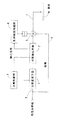
【0003】
このフィードバック制御のための構成を図解的に示せば、図6のとおりである。すなわち、処理液を基板Wに向けて供給するための供給経路105の途中部には、処理液の状態を変更するための状態変更手段101と、処理液の状態を検出するための状態検出手段102と、三方弁103とが介在されている。状態変更手段101は、たとえば、ヒータからなり、処理液の温度を変化させることができるものであり、この場合、状態検出手段102は処理液の温度を検出するための温度センサからなる。
【0004】
状態検出手段102は、検出結果に相当する温度検出信号を出力し、この温度検出信号に基づいて、状態制御部104が、処理液の温度を所定の温度に変化させるべく、状態変更手段101を制御する。これにより、基板Wに供給される処理液の温度がフィードバック制御される。
三方弁103は、供給経路105からの処理液を、基板W側、または状態変更手段101の上流側に処理液を帰還させるための循環経路106側に、選択的に供給することができるものである。基板W側に処理液が供給されない期間には、循環経路106を介して処理液が帰還され、これにより、基板Wの処理が開始される当初から所定の温度の処理液を基板Wに供給できるようにしている。
【0005】
【発明が解決しようとする課題】
ところが、上述の従来技術においては、たとえば、基板処理中に処理液の状態が変化した場合に、この状態変化した処理液を所望の状態に戻すまでにある程度の時間が必要である。また、処理液の循環によって、所定の状態の処理液を当初から供給しようとしてはいるものの、処理液が所定の状態に至る以前に基板Wの処理が開始される可能性は否定できない。
【0006】
したがって、上述の従来技術では、必ずしも所定の状態の処理液を基板Wに供給できるとは限らないから、複数枚の基板Wを処理する際に、処理の均一性が必ずしも良くなかった。
そこで、本発明の目的は、上述の技術的課題を解決し、基板に対する処理の均一性を確保することができる基板処理装置および基板処理方法を提供することである。
【0007】
【課題を解決するための手段】
上記の目的を達成するための請求項1記載の発明は、基板に対して予め定められた状態に調整された処理液を供給し、この処理液による処理を基板に施す基板処理装置であって、上記基板に対して供給される処理液の状態を検出し、検出結果に対応した検出信号を出力する状態検出手段と、この状態検出手段によって状態が検出された後の処理液を基板に供給するための処理液供給路と、上記状態検出手段が出力する検出信号に基づいて、処理液による基板の処理時間を制御する処理時間制御手段と、上記処理液の状態を変更するための状態変更手段と、上記状態検出手段が出力する検出信号に基づいて上記状態変更手段に制御信号を与えることにより、上記処理液の状態を前記予め定められた状態に調整するための状態制御手段とを含むことを特徴とする基板処理装置である。
【0008】
上記の構成によれば、基板の処理のために用いられる処理液の状態が状態検出手段によって検出され、この状態検出手段が出力する検出信号に基づいて状態変更手段が制御されることにより、処理液の状態が調整される。一方、状態検出手段の検出信号に基づき、処理液による基板の処理時間が制御され、これにより、処理液の状態に対応した最適な時間だけ、基板に対する処理を施すことができる。
【0009】
このように、この発明によれば、処理液の状態に応じて処理時間を最適化できるから、処理液の状態によらずに、基板に対して均一な処理を施すことができる。また、処理液の状態は、状態制御手段による状態変更手段の制御によって所定の状態に制御することができるから、処理液の状態はすみやかに安定するので、基板の処理時間は、ほぼ一定の時間に収束していくことになる。これにより、たとえば、複数枚の基板に対して処理を施す際に、当初は、処理液の温度が低いために長い処理時間を要するとしても、状態変更手段によって処理液の温度が上昇させられることにより、処理時間を短くしていくことができる。その結果、基板に対する処理を均一にできるだけでなく、複数枚の基板の処理時間を短縮することもできる。
【0010】
請求項2記載の発明は、上記処理液供給路から処理液が供給され、内部に蓄えた処理液中に基板を浸漬させることができる処理槽と、この処理槽に蓄えられた処理液に基板を出し入れするための基板出入れ手段とをさらに含み、上記処理時間制御手段は、上記基板出入れ手段による基板の出し入れのタイミングを制御することよって、処理液による基板の処理時間を制御するものであることを特徴とする請求項1記載の基板処理装置である。
【0011】
この構成によれば、処理槽に貯留された処理液中に基板を浸漬することによって、基板が処理される。基板は、基板出入れ手段によって、処理液に出し入れされる。基板は処理液に浸漬されている期間にのみ処理液の作用を受けるから、処理時間制御手段は、基板出入れ手段を制御することによって、処理液による基板の処理時間を制御することができる。
【0012】
請求項3の発明は、上記処理液供給路から処理液が供給され、内部に蓄えた処理液中に基板を浸漬させることができる処理槽と、この処理槽に蓄えられた処理液を排出するための処理液排出手段とをさらに含み、上記処理時間制御手段は、上記処理液排出手段による処理液の排出タイミングを制御することによって、処理液による基板の処理時間を制御するものであることを特徴とする請求項1記載の基板処理装置である。
【0013】
この構成によれば、請求項2の発明の場合と同じく、処理槽に貯留された処理液に基板を浸漬することによって、基板が処理される。ただし、この発明では、処理時間制御手段は、処理槽から処理液を排出するための処理液排出手段の動作タイミングを制御することによって、処理液による基板処理時間を制御する。すなわち、処理液の状態に対応した所定のタイミングで処理液を処理槽から排出させることによって、処理液による基板処理を停止させることができる。
【0014】
請求項4記載の発明は、上記処理液供給路に接続された弁と、この弁を介して上記処理液供給路に接続された処理液供給管と、この処理液供給管の先端に取り付けられ、基板に向けて処理液を噴出するためのノズルとをさらに含み、上記処理時間制御手段は上記弁を上記処理液供給管側に開放する時間を制御することによって、処理液による基板の処理時間を制御するものであることを特徴とする請求項1記載の基板処理装置。
なお、状態検出手段は、請求項5に記載されているように、処理液の温度、濃度、流量および圧力のうちの少なくとも1つを検出し、その検出結果に対応する検出信号を出力するものであってもよい。
請求項6記載の発明は、基板に対して予め定められた状態に調整された処理液を供給し、この処理液による処理を基板に施す基板処理方法であって、上記基板に対して供給される処理液の状態を検出する状態検出工程と、この状態検出工程によって状態が検出された後の処理液を基板に供給する工程と、上記状態検出工程によって検出される処理液の状態に基づいて処理液による基板の処理時間を制御する処理時間制御工程と、上記状態検出工程によって検出される処理液の状態に基づいて上記処理液の状態を前記予め定められた状態に調整する状態制御工程とを含むことを特徴とする基板処理方法である。
この方法により、請求項1の発明と同様な効果を達成できる。
【0015】
【発明の実施の形態】
以下では、本発明の実施の形態を、添付図面を参照して詳細に説明する。
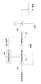
図1は、この発明の第1の実施形態に係る基板処理装置の基本的な構成を示すブロック図である。この基板処理装置は、半導体ウエハや液晶表示装置用ガラス基板などの基板Wに対してエッチング液などの処理液による処理を施すための装置である。
【0016】
この基板処理装置は、基板Wに処理液を供給するための処理液供給経路5の途中に、処理液の状態を変化させるための状態変更手段1と、処理液の状態を検出して、検出結果に対応する検出信号を出力する状態検出手段2と、三方弁3とを有している。基板処理装置は、さらに、状態検出手段2が出力する検出信号に基づいて状態変更手段1を制御する状態制御部4と、状態検出手段2が出力する検出信号に基づいて三方弁3を制御し、これにより基板Wに処理液が供給される時間を制御する処理時間制御部6とを有している。三方弁3には、基板Wに処理液を供給するための処理液供給管7と、処理液を処理液供給経路5において状態変更手段1よりも上流側に帰還させるための循環路管8とが接続されており、処理液供給管7と循環路管8とのうちのいずれか一方に三方弁3からの処理液が流通させられるようになっている。
【0017】
状態変更手段1は、たとえば、ヒータや冷却器のような熱交換装置からなり、処理液が流通する管や処理液を貯留するためのプロセスタンクに配置されて、処理液の温度を変化させるものであってもよい。この場合に、状態検出手段2は、基板Wに向けて供給される処理液の温度を検出して、検出温度に対応する温度検出信号を出力する温度センサからなる。したがって、状態制御部4は、状態検出手段2から入力される温度検出信号と、予め定められた設定温度とを比較し、その比較結果に基づいて、処理液の温度を設定温度に近づけるべく状態変更手段1を制御する。そして、処理時間制御部6は、状態検出手段2からの温度検出信号に基づいて三方弁3を制御し、検出温度に対応する時間だけ処理液供給管7側に処理液を供給する。これにより、基板Wには、処理液の温度に対応した時間だけ処理液が供給されることになる。
【0018】
基板Wに処理液が供給されない期間には、三方弁3は、循環路管8側に処理液を供給するように制御される。これにより、処理液は、状態変更手段1、状態検出手段2、三方弁3および循環路管8を順に通る閉ループを循環する。その結果、三方弁3から処理液供給管7側に処理液が供給されるときには、設定温度またはそれに近い温度の処理液を基板Wに供給することができる。
【0019】
状態制御部4および処理時間制御部6は、たとえば、マイクロコンピュータにより構成されてもよい。この場合に、状態制御部4および処理時間制御部6は、個別のマイクロコンピュータで構成されてもよく、共通のマイクロコンピュータが実行するソフトウエアによって状態制御部4および処理時間制御部6の各機能が実現されてもよい。
【0020】
状態変更手段1は、温度とともに、または温度の代わりに、処理液の濃度を変更することができるものであってもよい。この場合、状態変更手段1は、たとえば、処理用の薬液と、この薬液を所定濃度に薄めるための純水との混合比を変更するための混合比変更手段を含む。混合比変更手段は、たとえば、薬液と純水とを混合してプロセスタンクに供給するミキシングバルブであってもよい。
【0021】
状態変更手段1が処理液の濃度を変更することができるものである場合に、状態検出手段2は、温度センサとともに、または温度センサの代わりに、処理液の濃度を検出するための濃度センサを含む。この場合、状態検出手段2は、検出濃度に対応する濃度検出信号を出力する。そして、状態制御部4は、濃度検出信号に基づいて、処理液の濃度を予め定められた設定濃度に調整すべく、状態変更手段1を制御する。また、処理時間制御部6は、温度検出信号に代えて、または温度検出信号とともに、濃度検出信号を参照し、この濃度検出信号に基づいて、基板Wの処理時間を決定し、この決定された処理時間だけ処理液が処理液供給管7側に供給されるように三方弁3を制御する。
【0022】
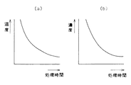
図2(a) は、たとえばエッチング液のような処理液の温度と適切な基板処理時間との関係を示す図であり、図2(b) は、処理液の濃度と適切な基板処理時間との関係を示す図である。この図2(a) および(b) から理解されるとおり、一般に、処理液の温度が高いほどその処理液による基板処理時間を短くすることが好ましく、処理液の濃度が高いほどその処理液による基板処理時間を短くすることが好ましい。
【0023】
そこで、処理時間制御部6は、図2に示されているような処理時間と温度および/または濃度との関係に基づいて基板Wに処理液を供給すべき時間を決定し、その時間の間だけ、三方弁3を処理液供給管7側に開放する。
以上のようにこの実施形態によれば、処理液の温度および/または濃度に基づいて、状態変更手段1がフィードバック制御され、かつ、基板Wの処理時間が制御される。基板Wの処理時間の制御は、供給途中の処理液の状態に基づいて、供給先(ユースポイント)における処理液の使用態様を変更するものであるから、いわばフィードフォワード制御であると言える。このように、この実施形態では、処理液の状態に基づく処理液の状態のフィードバック制御と、処理液の使用態様のフィードフォワード制御との組み合わせにより、処理液の状態の最適化とともに、処理時間の最適化が図られている。
【0024】
したがって、処理液の状態に対応して処理時間を設定することにより、複数枚の基板Wを処理する際に、各基板に均一な処理を施すことができる。また、処理液の状態をフィードバック制御することにより、処理液の状態をすみやかに所望の状態とすることができる。これにより、たとえば、複数枚の基板Wに対して処理を施す際に、当初は処理液の温度が低く、そのために長い処理時間を要する場合であっても、処理液の温度をすみやかに所望の温度まで上昇させることができるから、処理時間をすみやかに短縮していくことができる。したがって、複数枚の基板に対して均一な処理を施すことができるだけでなく、全体の処理時間を短縮できるという効果を併せて奏することができる。
【0025】
さらには、基板の処理時間を三方弁3の開閉によって決定するようにしているので、必要量の処理液のみが消費されることになるから、処理液の消費量を低減することができる。
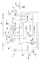
図3は、この発明の第2の実施形態に係る基板処理装置の基本的な構成を示すブロック図である。この基板処理装置は、プロセスタンク20に蓄積された薬液をポンプ21で汲み出し、薬液供給路22を介してミキシングバルブ11に供給し、このミキシングバルブ11において純水供給路23からの純水で薬液を希釈して得られた処理液を、処理液供給路24および三方弁13などを介して基板Wに供給するようにしたものである。三方弁13から基板Wに処理液を供給するための処理液供給管17の途中部には、処理液の圧力を検出するための圧力センサ25と、処理液の流量を検出するための流量センサ26とが配置されており、また、処理液供給管17の先端には、基板Wに向けて処理液を噴出するためのノズル27が取り付けられている。
【0026】
ミキシングバルブ11は、薬液供給路22を開閉するための第1弁11aと、純水供給路23を開閉するための第2弁11bと、純水の供給量を可変するための流量制御弁11cと、第1弁11aおよび流量制御弁11cからの薬液および純水を混合して処理液を作成するための混合室11dとを備えている。したがって、流量制御弁11cの開度を制御することによって、処理液供給路24に供給される処理液の濃度を制御することができる。処理液の濃度は、処理液供給路24の途中部に配置された濃度センサ28によって検出される。また、処理液の温度は、処理液供給路24の途中部に配置された温度センサ12によって検出される。
【0027】
プロセスタンク20には、薬液供給管14から薬液が供給されるようになっており、さらに、三方弁13からの処理液が循環路管18を通して帰還されるようになっている。そして、プロセスタンク20の内部には、薬液を加熱するためのヒータ15と、薬液を冷却するための冷却器19とが配置されており、さらに、薬液の温度を検出するための温度センサ29が配置されている。冷却器19には、冷却水が循環するようになっており、冷却水供給路には、冷却水供給弁19Aが配置されている。
【0028】
この基板処理装置には、処理液の状態や処理液による基板Wの処理時間を制御するために、マイクロコンピュータを有する制御装置30が備えられている。制御装置30には、処理液供給路24の途中部の温度センサ12、濃度センサ28、圧力センサ25、流量センサ26、およびプロセスタンク20内の温度センサ29がそれぞれ出力する検出信号が入力されている。これらのセンサ類からの検出信号に基づき、制御装置30は、ミキシングバルブ11の流量制御弁11cの開度、プロセスタンク20内のヒータ15への通電、および冷却水供給弁19Aの開閉を制御し、これにより、基板Wに供給される処理液の状態を変更するための状態変更手段として機能する。つまり、濃度センサ28が出力する濃度検出信号に基づいて流量制御弁11cの開度を制御することよって処理液の濃度が予め定める設定濃度に調整される。また、温度センサ12および29が出力する温度検出信号に基づいてヒータ15への通電を制御し、または冷却水供給弁19Aを開閉することにより、処理液の温度が予め定める設定温度に調整される。こうして、処理液の状態のフィードバック制御が達成される。
【0029】
制御装置30はさらに、上記センサ類からの検出信号に基づいて、基板Wを処理液により処理する際に、三方弁13を処理液供給管17側に開放する時間を制御し、これによって処理液による基板Wの処理時間を制御するための処理時間制御手段として機能する。すなわち、制御装置30は、温度センサ12、濃度センサ28、圧力センサ25、ならびに流量センサ26が出力する温度検出信号、濃度検出信号、圧力検出信号および流量検出信号に基づき、処理液の状態に対応する適切な処理時間を求め、この処理時間の間だけ、三方弁13から処理液供給管17に処理液を供給する。こうして、処理液の状態に応じて、基板Wの処理時間のフィードフォワード制御が実現される。
【0030】
処理時間の決定に際しては、一般に、処理液の温度および濃度に大きなウエイトが置かれる。さらに、たとえば基板Wに形成された薄膜のエッチングを行うような場合には、処理液の圧力および流量にも考慮して処理時間が定められることが好ましい。
以上のようにこの実施形態においても、処理液の状態のフィードバック制御と、処理液による基板Wの処理時間に関するフィードフォワード制御が行われるので、上述の第1の実施形態の場合と同様の効果を達成できる。
【0031】
なお、この実施形態の構成では、処理液の圧力および流量を可変制御するための構成は備えられていないが、たとえば、ポンプ21の制御により、あるいは、処理液供給管17の途中部にオートレギュレータを設けて、処理液の圧力を設定圧力にフィードバック制御するようにしてもよく、また、処理液供給管17の途中部に流量制御弁を設けて、処理液の流量を制御するようにしてもよい。
【0032】
また、この実施形態では、プロセスタンク20内に配置されたヒータ15および冷却器19によって処理液の温度制御が図られているが、このヒータ15および冷却器19に加えて、図3において二点鎖線で示すように、ミキシングバルブ11と温度センサ12との間の処理液供給路24に熱交換装置15Aを配置し、この熱交換装置15Aを制御装置30で制御するようにして、処理液の温度を設定温度に制御するようにすれば、温度制御性はさらに向上する。
【0033】
さらに、この実施形態では、プロセスタンク20から薬液を供給し、この薬液をミキシングバルブ11において純水で希釈することによって処理液が作成されているが、ミキシングバルブ11を設けずに、プロセスタンク20に予め作成された処理液を蓄積しておくようにしてもよい。この場合、処理液の濃度の制御は、プロセスタンク20に供給される薬液および純水の供給比を制御装置30によって制御することにより達成される。具体的には、プロセスタンクに向かう薬液供給路および純水供給路にそれぞれバルブを設けて、このバルブの開度や開放時間を制御すればよい。また、プロセスタンクに薬液および純水をそれぞれ供給するための薬液供給路および純水供給路からの薬液および純水をミキシングバルブで混合したうえでプロセスタンクに供給するようにしてもよい。この場合には、当該ミキシングバルブの制御によって、処理液の濃度の制御が達成されることになる。
【0034】
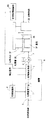
図4は、本発明の第3の実施形態に係る基板処理装置の基本的な構成を示すブロック図である。この図4において、上述の図1に示された各部に相当する部分には同一の参照符号を付して示し、第1の実施形態と異なる点を中心に説明する。
この実施形態の基板処理装置は、処理槽35内に貯留された処理液36に基板Wを浸漬して、この基板Wに処理液36による処理を施すものである。処理槽35に関連して、基板Wを保持するための保持手段37と、この保持手段37を昇降することによって基板Wを処理液36に出し入れするための移動手段38とが配置されており、この保持手段37および移動手段38が基板出入れ手段を構成している。そして、移動手段38の動作が、処理時間制御部6Aによって制御されるようになっている。保持手段37は、1枚の基板Wを保持することができるものであってもよく、また、複数枚の基板Wを処理液による処理が可能な状態で保持することができる基板カセットを保持できるように構成されたものであってもよい。
【0035】
三方弁3から処理液供給管7を通った処理液は、処理槽35に供給されるようになっている。また、処理液供給経路5に介装されている状態検出手段2が出力する検出信号は、処理時間制御部6Aに与えられる。処理時間制御部6Aは、状態検出手段2が出力する検出信号に基づいて、基板Wの処理時間を決定する。基板Wに対する処理の開始に当たり、処理時間制御部6Aは、移動手段38に下降制御信号を出力する。これにより、移動手段38は、保持手段37を下降させ、基板Wを処理液36に浸漬させる。そして、基板Wが処理液36に浸漬された後、上記検出信号に基づいて決定された処理時間が経過すると、処理時間制御部6Aは、移動手段38に上昇制御信号を与える。これにより、移動手段38は保持手段37を上昇させ、基板Wを処理液36外に取り出す。こうして、状態検出手段2によって検出された処理液の状態に対応した時間だけ、処理液による処理を基板Wに施すことができる。
【0036】
処理液供給経路5に配置された状態変更手段1が状態検出手段2の検出信号に基づいてフィードバック制御される点は、第1の実施形態の場合と同様である。図5は、この発明の第4の実施形態に係る基板処理装置の基本的な構成を示すブロック図である。この図5においては、上述の図1に示された各部に相当する部分には同一の参照符号が付されており、以下では、第1の実施形態と相違する点を中心に説明する。
【0037】
この基板処理装置は、第3の実施形態の場合と同じく、処理槽35Aに貯留された処理液36Aに基板Wを浸漬して、この基板Wに処理を施す形態のものである。処理槽35Aは、底面に排液口41を有しており、この排液口41は排液管42に結合されている。排液管42の途中部には、処理液排出手段43が配設されている。処理液排出手段43は、排液管42を開閉する弁からなる。
【0038】
処理液排出手段43の開閉動作は、処理時間制御部6Bにより制御される。処理時間制御部6Bは、処理液供給経路5の途中に設けられた状態検出手段2が出力する検出信号に基づいて、処理液排出手段43の動作を制御する。処理時間制御部6Bは、また、三方弁3を開閉制御する。三方弁3から処理液供給管7に導かれた処理液は、処理槽35Aに供給されるようになっている。
【0039】
基板Wに対する処理に際しては、まず、処理槽35A内に、予め1枚または複数枚の基板Wが収容され、処理液排出手段43は排液管42を閉塞した状態に制御される。その後、処理時間制御部6Bの制御の下、三方弁3が開放されて処理液が処理槽35Aに供給される。処理槽35A内に必要量の処理液36Aが貯留されると、三方弁3が閉塞され、処理液は循環路管8に流通させられる。処理時間制御部6Bは、状態検出手段2からの検出信号に基づいて、処理液により基板Wに処理を施すべき処理時間を予め演算しており、三方弁3を処理液供給管7側に開放した時点(または三方弁3を処理液供給管7に対して閉塞した時点)から、上記演算された処理時間が経過したことに応答して、処理液排出手段43を開成して、処理槽35A内の処理液36Aを排出させる。これにより、処理槽35A内の基板Wには、状態検出手段2によって検出された処理液の状態に対応した時間だけ、処理液による処理が施されることになる。処理液36Aの処理槽35Aからの排出と並行して、他の種類の処理液を処理槽35Aに供給すれば、複数種類の処理液による処理を連続的に行うことができる。
【0040】
なお、処理液供給経路5に配置された状態変更手段1が状態検出手段2の検出信号に基づいてフィードバック制御される点は、第1の実施形態の場合と同様である。
このように、上記第3および第4の実施形態のいずれにおいても、処理液の状態を所定の状態にするためのフィードバック制御と、処理液の状態に対応した時間だけ基板Wに処理を施すためのフィードフォワード制御とが組み合わせられて行われている。これにより、上記第1の実施形態の場合と同様な効果が達成される。
【0041】
以上、この発明の4つの実施形態について説明したが、この発明が他の実施形態を採りうることはいうまでもない。たとえば、第3の実施形態においては、処理液に対する基板の出し入れのために、基板を保持した保持手段を昇降させているが、処理槽を昇降させることによっても、基板を処理液に対して出し入れすることができる。
【0042】
その他、特許請求の範囲に記載された技術的事項の範囲で種々の設計変更を施すことが可能である。
【0043】
【発明の効果】
以上のように本発明によれば、処理液の状態に応じて処理時間を最適化できるから、処理液の状態によらずに、基板に対して均一な処理を施すことができる。また、状態制御手段による状態変更手段の制御によって、処理液の状態を所定の状態に制御できるから、処理液の状態はすみやかに安定する。これにより、たとえば、複数枚の基板に対して処理を施す際に、当初は、処理液の温度が低いために長い処理時間を要するとしても、状態変更手段によって処理液の温度が上昇させられることにより、処理時間を短くしていくことができる。その結果、基板に対する処理を均一にできるだけでなく、複数枚の基板に対する総処理時間の短縮を併せて達成できる。
【図面の簡単な説明】
【図1】この発明の第1の実施形態に係る基板処理装置の基本的な構成を示すブロック図である。
【図2】処理液の状態と最適処理時間との関係を示すグラフであり、(a) は処理液の温度と処理時間との関係を示し、(b) は処理液の濃度と処理時間との関係を示す。
【図3】この発明の第2の実施形態に係る基板処理装置の基本的な構成を示すブロック図である。
【図4】この発明の第3の実施形態に係る基板処理装置の基本的な構成を示すブロック図である。
【図5】この発明の第4の実施形態に係る基板処理装置の基本的な構成を示すブロック図である。
【図6】従来の基板処理装置の構成を示すブロック図である。
【符号の説明】
1 状態変更手段
2 状態検出手段
3 三方弁
4 状態制御部
5 処理液供給経路
6 処理時間制御部
7 処理液供給管
11 ミキシングバルブ
12 温度センサ
13 三方弁
15 ヒータ
17 処理液供給管
19 冷却器
20 プロセスタンク
21 ポンプ
24 処理液供給路
25 圧力センサ
26 流量センサ
28 濃度センサ
29 温度センサ
30 制御装置
35 処理槽
36 処理液
37 保持手段
38 移動手段
6A 処理時間制御部
35A 処理槽
36A 処理液
43 処理液排出手段
6B 処理時間制御部[0001]
BACKGROUND OF THE INVENTION
The present invention relates to a substrate processing apparatus for processing a substrate such as a semiconductor wafer or a glass substrate for a liquid crystal display device. And substrate processing method About.
[0002]
[Prior art]
In the manufacturing process of a semiconductor device or a liquid crystal display device, a substrate processing step using a processing liquid is used to form a thin film on a semiconductor wafer or a glass substrate for a liquid crystal display device, or to etch and pattern the thin film. It is essential. However, in wet etching, for example, the etching progress rate greatly depends on the temperature and / or concentration of the processing liquid (etching liquid). Therefore, in the conventional substrate processing apparatus, the temperature and concentration of the processing liquid are detected in the supply path of the processing liquid, and the temperature and concentration of the processing liquid are feedback controlled based on the detection result.
[0003]
A configuration for this feedback control is schematically shown in FIG. That is, in the middle of the
[0004]
The
The three-
[0005]
[Problems to be solved by the invention]
However, in the above-described prior art, for example, when the state of the processing liquid changes during the substrate processing, a certain amount of time is required to return the processing liquid whose state has changed to a desired state. In addition, although the processing liquid in a predetermined state is going to be supplied from the beginning by circulation of the processing liquid, the possibility that the processing of the substrate W is started before the processing liquid reaches the predetermined state cannot be denied.
[0006]
Therefore, in the above-described prior art, the processing liquid in a predetermined state cannot always be supplied to the substrate W, and thus the processing uniformity is not always good when processing a plurality of substrates W.
SUMMARY OF THE INVENTION Accordingly, an object of the present invention is to solve the above-described technical problems and to ensure the uniformity of processing on a substrate. And substrate processing method Is to provide.
[0007]
[Means for Solving the Problems]
In order to achieve the above object, the invention according to
[0008]
According to the above configuration, the state of the processing liquid used for processing the substrate is detected by the state detecting unit, and the state changing unit is controlled based on the detection signal output from the state detecting unit, thereby The state of the liquid is adjusted. On the other hand, the processing time of the substrate by the processing liquid is controlled based on the detection signal of the state detecting means, and thus the substrate can be processed for an optimum time corresponding to the state of the processing liquid.
[0009]
Thus, according to the present invention, the processing time can be optimized in accordance with the state of the processing liquid, so that the substrate can be uniformly processed regardless of the state of the processing liquid. In addition, since the state of the processing liquid can be controlled to a predetermined state by the control of the state changing unit by the state control unit, the state of the processing liquid is quickly stabilized, so that the processing time of the substrate is a substantially constant time. Will converge. Thereby, for example, when processing a plurality of substrates, the temperature of the processing liquid can be raised by the state changing unit even if a long processing time is required because the temperature of the processing liquid is initially low. Thus, the processing time can be shortened. As a result, not only the processing on the substrate can be made uniform, but also the processing time for a plurality of substrates can be shortened.
[0010]
According to the second aspect of the present invention, the processing liquid is supplied from the processing liquid supply path and the substrate can be immersed in the processing liquid stored therein, and the processing liquid stored in the processing tank has a substrate. A substrate loading / unloading means for loading / unloading the substrate, and the processing time control means controls the processing time of the substrate by the processing liquid by controlling the timing of loading / unloading the substrate by the substrate loading / unloading means. The substrate processing apparatus according to
[0011]
According to this configuration, the substrate is processed by immersing the substrate in the processing liquid stored in the processing tank. Substrate can be used Yo Then, it is put in and out of the processing liquid. Since the substrate receives the action of the treatment liquid only during the period in which the substrate is immersed in the treatment liquid, the treatment time control means can control the treatment time of the substrate by the treatment liquid by controlling the substrate loading / unloading means.
[0012]
According to a third aspect of the present invention, the processing liquid is supplied from the processing liquid supply path, the processing tank capable of immersing the substrate in the processing liquid stored inside, and the processing liquid stored in the processing tank are discharged. A processing liquid discharge means for controlling the processing time of the substrate by the processing liquid by controlling the discharge timing of the processing liquid by the processing liquid discharging means. The substrate processing apparatus according to
[0013]
According to this configuration, the substrate is processed by immersing the substrate in the processing liquid stored in the processing tank, as in the case of the invention of
[0014]
The invention according to claim 4 is attached to a valve connected to the processing liquid supply path, a processing liquid supply pipe connected to the processing liquid supply path via the valve, and a tip of the processing liquid supply pipe. And a nozzle for ejecting the processing liquid toward the substrate, and the processing time control means controls the time for opening the valve to the processing liquid supply pipe side to thereby process the substrate with the processing liquid. 2. The substrate processing apparatus according to
In addition, as described in
The invention according to
By this method, the same effect as that of the invention of
[0015]
DETAILED DESCRIPTION OF THE INVENTION
Hereinafter, embodiments of the present invention will be described in detail with reference to the accompanying drawings.
FIG. 1 is a block diagram showing a basic configuration of a substrate processing apparatus according to the first embodiment of the present invention. This substrate processing apparatus is an apparatus for processing a substrate W such as a semiconductor wafer or a glass substrate for a liquid crystal display device with a processing liquid such as an etching liquid.
[0016]
This substrate processing apparatus detects and detects the state of the processing liquid and the state changing means 1 for changing the state of the processing liquid in the middle of the processing
[0017]
The state changing means 1 is composed of, for example, a heat exchange device such as a heater or a cooler, and is arranged in a pipe through which the processing liquid flows or a process tank for storing the processing liquid, and changes the temperature of the processing liquid. It may be. In this case, the
[0018]
During a period when the processing liquid is not supplied to the substrate W, the three-
[0019]
The state control unit 4 and the processing
[0020]
The state change means 1 may be capable of changing the concentration of the treatment liquid together with the temperature or instead of the temperature. In this case, the state changing means 1 includes, for example, a mixing ratio changing means for changing the mixing ratio of the chemical for processing and the pure water for diluting the chemical to a predetermined concentration. The mixing ratio changing means may be, for example, a mixing valve that mixes a chemical solution and pure water and supplies them to the process tank.
[0021]
When the
[0022]
FIG. 2 (a) is a diagram showing the relationship between the temperature of a processing solution such as an etching solution and an appropriate substrate processing time, and FIG. 2 (b) shows the concentration of the processing solution and the appropriate substrate processing time. It is a figure which shows the relationship. As understood from FIGS. 2 (a) and 2 (b), it is generally preferable that the substrate processing time by the processing liquid is shortened as the temperature of the processing liquid is higher, and that the higher the concentration of the processing liquid, It is preferable to shorten the substrate processing time.
[0023]
Therefore, the processing
As described above, according to this embodiment, the
[0024]
Therefore, by setting the processing time corresponding to the state of the processing liquid, it is possible to perform uniform processing on each substrate when processing a plurality of substrates W. Further, by performing feedback control of the state of the processing liquid, the state of the processing liquid can be quickly changed to a desired state. Thereby, for example, when processing a plurality of substrates W, the temperature of the processing liquid is initially low, and thus a long processing time is required. Since the temperature can be increased, the processing time can be quickly shortened. Therefore, not only a uniform processing can be performed on a plurality of substrates, but also the effect that the entire processing time can be shortened can be achieved.
[0025]
Furthermore, since the processing time of the substrate is determined by opening and closing the three-
FIG. 3 is a block diagram showing a basic configuration of a substrate processing apparatus according to the second embodiment of the present invention. The substrate processing apparatus pumps out the chemical solution accumulated in the
[0026]
The mixing
[0027]
A chemical liquid is supplied to the
[0028]
In order to control the state of the processing liquid and the processing time of the substrate W by the processing liquid, the substrate processing apparatus is provided with a
[0029]
The
[0030]
In determining the processing time, a large weight is generally placed on the temperature and concentration of the processing liquid. Further, for example, when etching a thin film formed on the substrate W, it is preferable that the processing time is determined in consideration of the pressure and flow rate of the processing liquid.
As described above, also in this embodiment, since the feedback control of the state of the processing liquid and the feedforward control regarding the processing time of the substrate W by the processing liquid are performed, the same effects as in the case of the first embodiment described above are obtained. Can be achieved.
[0031]
The configuration of this embodiment is not provided with a configuration for variably controlling the pressure and flow rate of the processing liquid. For example, an auto regulator is controlled by the
[0032]
In this embodiment, the temperature of the processing liquid is controlled by the
[0033]
Further, in this embodiment, a chemical solution is prepared by supplying a chemical solution from the
[0034]
FIG. 4 is a block diagram showing a basic configuration of a substrate processing apparatus according to the third embodiment of the present invention. In FIG. 4, portions corresponding to the respective portions shown in FIG. 1 described above are given the same reference numerals, and different points from the first embodiment will be mainly described.
In the substrate processing apparatus of this embodiment, the substrate W is immersed in the processing liquid 36 stored in the processing tank 35 and the substrate W is processed with the processing liquid 36. In relation to the processing tank 35, a holding means 37 for holding the substrate W and a moving means 38 for moving the substrate W into and out of the processing liquid 36 by moving the holding means 37 up and down are arranged. The holding means 37 and the moving means 38 constitute a substrate taking-in / out means. Then, the operation of the moving means 38 is controlled by the processing time control unit 6A. The holding means 37 may be capable of holding a single substrate W, and can hold a substrate cassette capable of holding a plurality of substrates W in a state where processing with a processing liquid is possible. It may be configured as described above.
[0035]
The processing liquid that has passed through the processing
[0036]
The point that the state changing means 1 arranged in the processing
[0037]
As in the case of the third embodiment, this substrate processing apparatus is configured to immerse the substrate W in the
[0038]
The opening / closing operation of the processing liquid discharge means 43 is controlled by the processing time control unit 6B. The processing
[0039]
When processing the substrate W, first, one or a plurality of substrates W are accommodated in advance in the processing tank 35A, and the processing liquid discharge means 43 is controlled to be closed. Thereafter, under the control of the processing time control unit 6B, the three-
[0040]
The point that the
As described above, in any of the third and fourth embodiments, the substrate W is processed only for the time corresponding to the feedback control for setting the state of the processing liquid to a predetermined state and the state of the processing liquid. This is combined with feedforward control. Thereby, the same effect as in the case of the first embodiment is achieved.
[0041]
As mentioned above, although four embodiment of this invention was described, it cannot be overemphasized that this invention can take other embodiment. For example, in the third embodiment, the holding means for holding the substrate is moved up and down for loading and unloading the substrate with respect to the processing liquid. However, the substrate can be taken in and out by moving the processing tank up and down. can do.
[0042]
In addition, various design changes can be made within the scope of technical matters described in the claims.
[0043]
【The invention's effect】
As described above, according to the present invention, the processing time can be optimized according to the state of the processing liquid, so that the substrate can be uniformly processed regardless of the state of the processing liquid. Further, since the state of the processing liquid can be controlled to a predetermined state by the control of the state changing unit by the state control unit, the state of the processing liquid is quickly stabilized. Thereby, for example, when processing a plurality of substrates, the temperature of the processing liquid can be raised by the state changing unit even if a long processing time is required because the temperature of the processing liquid is initially low. Thus, the processing time can be shortened. As a result, not only the processing on the substrates can be made uniform, but also the total processing time for a plurality of substrates can be shortened.
[Brief description of the drawings]
FIG. 1 is a block diagram showing a basic configuration of a substrate processing apparatus according to a first embodiment of the present invention.
FIG. 2 is a graph showing the relationship between the state of the treatment liquid and the optimum treatment time, where (a) shows the relationship between the temperature of the treatment liquid and the treatment time, and (b) shows the concentration of the treatment liquid and the treatment time. The relationship is shown.
FIG. 3 is a block diagram showing a basic configuration of a substrate processing apparatus according to a second embodiment of the present invention.
FIG. 4 is a block diagram showing a basic configuration of a substrate processing apparatus according to a third embodiment of the present invention.
FIG. 5 is a block diagram showing a basic configuration of a substrate processing apparatus according to a fourth embodiment of the present invention.
FIG. 6 is a block diagram showing a configuration of a conventional substrate processing apparatus.
[Explanation of symbols]
1 State change means
2 State detection means
3 Three-way valve
4 State control unit
5 Treatment liquid supply path
6 Processing time controller
7 Treatment liquid supply pipe
11 Mixing valve
12 Temperature sensor
13 Three-way valve
15 Heater
17 Treatment liquid supply pipe
19 Cooler
20 Process tank
21 Pump
24 Treatment liquid supply path
25 Pressure sensor
26 Flow sensor
28 Concentration sensor
29 Temperature sensor
30 Control device
35 treatment tank
36 Treatment liquid
37 Holding means
38 Moving means
6A Processing time controller
35A treatment tank
36A Treatment liquid
43 Processing liquid discharge means
6B Processing time controller
Claims (6)
上記基板に対して供給される処理液の状態を検出し、検出結果に対応した検出信号を出力する状態検出手段と、
この状態検出手段によって状態が検出された後の処理液を基板に供給するための処理液供給路と、
上記状態検出手段が出力する検出信号に基づいて、処理液による基板の処理時間を制御する処理時間制御手段と、
上記処理液の状態を変更するための状態変更手段と、
上記状態検出手段が出力する検出信号に基づいて上記状態変更手段に制御信号を与えることにより、上記処理液の状態を前記予め定められた状態に調整するための状態制御手段とを含むことを特徴とする基板処理装置。A substrate processing apparatus that supplies a processing liquid adjusted to a predetermined state with respect to a substrate and performs processing on the substrate with the processing liquid,
State detecting means for detecting the state of the processing liquid supplied to the substrate and outputting a detection signal corresponding to the detection result;
A treatment liquid supply path for supplying the treatment liquid after the state is detected by the state detection means to the substrate;
A processing time control means for controlling the processing time of the substrate by the processing liquid based on the detection signal output by the state detection means;
State changing means for changing the state of the treatment liquid;
By applying control signals to said state changing means based on a detection signal output from said state detecting means, characterized in that it comprises a state control means for adjusting the state of the processing solution in a state where said predetermined A substrate processing apparatus.
この処理槽に蓄えられた処理液に基板を出し入れするための基板出入れ手段とをさらに含み、
上記処理時間制御手段は、上記基板出入れ手段による基板の出し入れのタイミングを制御することよって、処理液による基板の処理時間を制御するものであることを特徴とする請求項1記載の基板処理装置。A treatment tank that is supplied with the treatment liquid from the treatment liquid supply path and can immerse the substrate in the treatment liquid stored inside,
A substrate loading / unloading means for loading / unloading the substrate into / from the processing liquid stored in the processing tank;
2. The substrate processing apparatus according to claim 1, wherein the processing time control means controls the processing time of the substrate by the processing liquid by controlling the timing at which the substrate is taken in and out by the substrate taking in and out means. .
この処理槽に蓄えられた処理液を排出するための処理液排出手段とをさらに含み、
上記処理時間制御手段は、上記処理液排出手段による処理液の排出タイミングを制御することによって、処理液による基板の処理時間を制御するものであることを特徴とする請求項1記載の基板処理装置。A treatment tank that is supplied with the treatment liquid from the treatment liquid supply path and can immerse the substrate in the treatment liquid stored inside,
And further including a processing liquid discharge means for discharging the processing liquid stored in the processing tank,
2. The substrate processing apparatus according to claim 1, wherein the processing time control means controls the processing time of the substrate by the processing liquid by controlling the discharge timing of the processing liquid by the processing liquid discharging means. .
この弁を介して上記処理液供給路に接続された処理液供給管と、
この処理液供給管の先端に取り付けられ、基板に向けて処理液を噴出するためのノズルとをさらに含み、
上記処理時間制御手段は上記弁を上記処理液供給管側に開放する時間を制御することによって、処理液による基板の処理時間を制御するものであることを特徴とする請求項1記載の基板処理装置。A valve connected to the treatment liquid supply path;
A treatment liquid supply pipe connected to the treatment liquid supply path via this valve;
A nozzle that is attached to the tip of the processing liquid supply pipe and that ejects the processing liquid toward the substrate;
2. The substrate processing according to claim 1, wherein the processing time control means controls a processing time of the substrate by the processing liquid by controlling a time for opening the valve to the processing liquid supply pipe side. apparatus.
上記基板に対して供給される処理液の状態を検出する状態検出工程と、
この状態検出工程によって状態が検出された後の処理液を基板に供給する工程と、
上記状態検出工程によって検出される処理液の状態に基づいて処理液による基板の処理時間を制御する処理時間制御工程と、
上記状態検出工程によって検出される処理液の状態に基づいて上記処理液の状態を前記予め定められた状態に調整する状態制御工程とを含むことを特徴とする基板処理方法。A substrate processing method of supplying a processing liquid adjusted to a predetermined state with respect to a substrate and performing processing on the substrate with the processing liquid,
A state detection step of detecting the state of the processing liquid supplied to the substrate;
Supplying the processing liquid after the state is detected by the state detection step to the substrate;
A processing time control step for controlling the processing time of the substrate by the processing liquid based on the state of the processing liquid detected by the state detection step;
The substrate processing method characterized by including the state control step of adjusting a state of the processing solution based on the state of the processing liquid detected by the state detecting step in a state where said predetermined.
Priority Applications (1)
| Application Number | Priority Date | Filing Date | Title |
|---|---|---|---|
| JP19754096A JP3761981B2 (en) | 1996-07-26 | 1996-07-26 | Substrate processing apparatus and substrate processing method |
Applications Claiming Priority (1)
| Application Number | Priority Date | Filing Date | Title |
|---|---|---|---|
| JP19754096A JP3761981B2 (en) | 1996-07-26 | 1996-07-26 | Substrate processing apparatus and substrate processing method |
Publications (2)
| Publication Number | Publication Date |
|---|---|
| JPH1041268A JPH1041268A (en) | 1998-02-13 |
| JP3761981B2 true JP3761981B2 (en) | 2006-03-29 |
Family
ID=16376184
Family Applications (1)
| Application Number | Title | Priority Date | Filing Date |
|---|---|---|---|
| JP19754096A Expired - Fee Related JP3761981B2 (en) | 1996-07-26 | 1996-07-26 | Substrate processing apparatus and substrate processing method |
Country Status (1)
| Country | Link |
|---|---|
| JP (1) | JP3761981B2 (en) |
-
1996
- 1996-07-26 JP JP19754096A patent/JP3761981B2/en not_active Expired - Fee Related
Also Published As
| Publication number | Publication date |
|---|---|
| JPH1041268A (en) | 1998-02-13 |
Similar Documents
| Publication | Publication Date | Title |
|---|---|---|
| US6399517B2 (en) | Etching method and etching apparatus | |
| US8950414B2 (en) | Liquid processing apparatus, liquid processing method, and storage medium | |
| JP5714449B2 (en) | Liquid processing apparatus, liquid processing method, and storage medium | |
| TWI385026B (en) | Treatment liquid mixing device, substrate treatment device, treatment liquid mixing method, and storage medium | |
| KR101042805B1 (en) | Substrate treating apparatus and substrate treating method | |
| JP2013045972A5 (en) | ||
| JP5220707B2 (en) | Liquid processing apparatus, liquid processing method, program, and program recording medium | |
| JP2009172459A5 (en) | ||
| JPH0534054B2 (en) | ||
| JP3761981B2 (en) | Substrate processing apparatus and substrate processing method | |
| US20060157197A1 (en) | Substrate processing apparatus | |
| JP2009260257A (en) | Substrate treating apparatus and substrate treating method | |
| JP2000021838A (en) | Substrate treatment device | |
| JP4515269B2 (en) | Substrate processing equipment | |
| JP3425393B2 (en) | Spray heat treatment equipment | |
| JP2011035133A (en) | Liquid processing apparatus and liquid processing method | |
| JP3306263B2 (en) | Substrate processing equipment | |
| JP3739952B2 (en) | Substrate processing equipment | |
| JP3361676B2 (en) | Substrate processing method and apparatus | |
| JP3773390B2 (en) | Substrate processing equipment | |
| JP3630543B2 (en) | Substrate processing equipment | |
| KR102643103B1 (en) | Apparatus for treating substrate | |
| KR20240078334A (en) | Substrate processing method and substrate processing system | |
| JP2002158200A (en) | Substrate treating apparatus | |
| JP3492901B2 (en) | Substrate surface treatment method and surface treatment device |
Legal Events
| Date | Code | Title | Description |
|---|---|---|---|
| A521 | Written amendment |
Free format text: JAPANESE INTERMEDIATE CODE: A523 Effective date: 20051208 |
|
| A61 | First payment of annual fees (during grant procedure) |
Free format text: JAPANESE INTERMEDIATE CODE: A61 Effective date: 20060112 |
|
| R150 | Certificate of patent or registration of utility model |
Free format text: JAPANESE INTERMEDIATE CODE: R150 |
|
| FPAY | Renewal fee payment (event date is renewal date of database) |
Free format text: PAYMENT UNTIL: 20090120 Year of fee payment: 3 |
|
| FPAY | Renewal fee payment (event date is renewal date of database) |
Free format text: PAYMENT UNTIL: 20100120 Year of fee payment: 4 |
|
| FPAY | Renewal fee payment (event date is renewal date of database) |
Free format text: PAYMENT UNTIL: 20100120 Year of fee payment: 4 |
|
| FPAY | Renewal fee payment (event date is renewal date of database) |
Free format text: PAYMENT UNTIL: 20100120 Year of fee payment: 4 |
|
| FPAY | Renewal fee payment (event date is renewal date of database) |
Free format text: PAYMENT UNTIL: 20110120 Year of fee payment: 5 |
|
| FPAY | Renewal fee payment (event date is renewal date of database) |
Free format text: PAYMENT UNTIL: 20110120 Year of fee payment: 5 |
|
| FPAY | Renewal fee payment (event date is renewal date of database) |
Free format text: PAYMENT UNTIL: 20120120 Year of fee payment: 6 |
|
| FPAY | Renewal fee payment (event date is renewal date of database) |
Free format text: PAYMENT UNTIL: 20120120 Year of fee payment: 6 |
|
| FPAY | Renewal fee payment (event date is renewal date of database) |
Free format text: PAYMENT UNTIL: 20130120 Year of fee payment: 7 |
|
| FPAY | Renewal fee payment (event date is renewal date of database) |
Free format text: PAYMENT UNTIL: 20130120 Year of fee payment: 7 |
|
| FPAY | Renewal fee payment (event date is renewal date of database) |
Free format text: PAYMENT UNTIL: 20130120 Year of fee payment: 7 |
|
| FPAY | Renewal fee payment (event date is renewal date of database) |
Free format text: PAYMENT UNTIL: 20140120 Year of fee payment: 8 |
|
| R250 | Receipt of annual fees |
Free format text: JAPANESE INTERMEDIATE CODE: R250 |
|
| R250 | Receipt of annual fees |
Free format text: JAPANESE INTERMEDIATE CODE: R250 |
|
| S533 | Written request for registration of change of name |
Free format text: JAPANESE INTERMEDIATE CODE: R313533 |
|
| R350 | Written notification of registration of transfer |
Free format text: JAPANESE INTERMEDIATE CODE: R350 |
|
| LAPS | Cancellation because of no payment of annual fees |