JP3761663B2 - Sample weighing and conveying device for moisture meter - Google Patents
Sample weighing and conveying device for moisture meter Download PDFInfo
- Publication number
- JP3761663B2 JP3761663B2 JP11467097A JP11467097A JP3761663B2 JP 3761663 B2 JP3761663 B2 JP 3761663B2 JP 11467097 A JP11467097 A JP 11467097A JP 11467097 A JP11467097 A JP 11467097A JP 3761663 B2 JP3761663 B2 JP 3761663B2
- Authority
- JP
- Japan
- Prior art keywords
- sample
- heating tube
- measurement
- lid
- unit
- Prior art date
- Legal status (The legal status is an assumption and is not a legal conclusion. Google has not performed a legal analysis and makes no representation as to the accuracy of the status listed.)
- Expired - Lifetime
Links
Images


Landscapes
- Sampling And Sample Adjustment (AREA)
Description
【0001】
【発明の属する技術分野】
本発明は、水分計用試料計量搬送装置に関する。特に短時間での測定を可能にし且つ外気湿気の影響を受け難い水分計用の試料計量搬送装置に関する。
【0002】
【従来の技術】
従来より、固体又は液体中の水分量を測定する高精度の水分定量法として、カールフィッシャー法(KF法)が広く知られている。KF法は、ヨウ素、二酸化硫黄、ピリジン、メタノールを成分とするカールフィッシャー試薬が水と定量的に反応することを利用するものである。しかしながら、KF法による水分量の測定では、測定対象物によっては各種の修正が必要になり、正確な水分量を求めるには、相当な熟練を必要としていた。また、測定においては、特殊な試薬やガラス容器が必要になるという問題もあった。
【0003】
KF法の上記問題点を解決するために、加熱乾燥型の水分計が開発されてきた。このような加熱乾燥型の水分計としては、例えば、特開平7−12696号公報に記載されているもののように、キャリアガスを生成する気体導入部と、この気体導入部からキャリアガスを導入して被測定物を加熱する加熱部と、この加熱部から導出されるキャリアガスから気化水分を補集する水分収集部と、前記水分収集部の増加重量を検出する電子天秤ユニットとを備えているようなものが挙げられる。そして、このような水分計は、被測定物を加熱して、被測定物中の水分を気化させ、この気化させた水分を補集、計量することで被測定物の水分量を測定するという作用を有することができるものであり、被測定物を加熱部へ移動させるには特開平7−12700号公報に記載されるようなラック及びピニオンによる磁力式の搬送装置が採用されていた。
【0004】
【発明が解決しようとする課題】
ところが、従来の搬送装置は、加熱管内の測定試料を非加熱部から測定部に移動させるにすぎず、測定試料の質量の計量及び加熱管内への測定試料の挿入は測定者によらなければならなかった。このため、測定試料が外気に触れる時間にばらつきがあり、また、加熱管内へ試料を挿入させるためには、横置きの加熱管の蓋を開ける必要があり、加熱管内部への外気の流入を避けることができないという問題があった。
更に、加熱管の蓋は、良好な密閉性を達成するために容易に開閉を行なうことができないような構造にせざるを得ず、その操作性に問題を有しており、且つ搬送装置の駆動部は直接加熱部へ挿入されるためその部材には耐熱性が要求され、吸水、熱変形、加熱によるガスの発生等が生じないような部品を用いざるを得ないという構造上の制限も課せられていた。
【0005】
そしてまた、磁力式の搬送装置においては、その周りの金属を磁化させてしまうので、搬送装置周辺の環境に十分注意しなければならなかった。すなわち、磁石に影響を及ぼす試料(磁石に引き付けられる成分を含む試料等)を測定する場合には、測定試料がサンプル皿から取れ難かったり、こぼれた試料が加熱管内で磁石に引き付けられ、メンテナンスが困難になる場合があった。また、ディスク(FD)等は磁石によりデータが破壊されるため、機器周辺での使用には極めて注意しなければならなかった。
一方、磁石の磁力自身も温度に依存するため、長期使用に伴い交換が必要となり、交換不要とするには必要以上に強力な磁力の磁石を使用しなければならないという不都合もあった。
【0006】
そこで、本発明は、試料中の水分量の測定を、試料の種類に制限されることなく一定時間において簡便に行なうことができ、且つ外部湿気等の外部環境の影響による誤差が生じにくく安定した測定値を得ることができる、水分計用の試料計量搬送装置の提供を目的とする。
【0007】
【発明を解決するための手段】
上記の目的を達成するために、本発明は、一端が開口した加熱管を開口端が下部になるよう縦置きにして備えられた加熱部内において測定試料中の水分を加熱により気化させ、キャリアガスと共に携行し、この気化水分のみを補集し検知することで測定試料中の水分量を測定する水分計用の試料計量搬送装置であって、測定試料の質量測定手段と測定試料の搬送手段とを備え、
前記測定試料の質量測定手段は、サンプルケースを備えた測定試料挿入計量部と電子天秤部とを有し、前記サンプルケースは、上下運動及び加熱管下部への横移動可能に設けられ下降することによって前記電子天秤部の測定試料計量部と接触し、試料の質量を計量可能にするよう構成され、
前記測定試料の搬送手段は、前記サンプルケースと、前記サンプルケースの上部に設けられたサンプルケース蓋と、前記加熱管の下部開口端に配された加熱管蓋とが横方向に連動するよう構成され、非測定時には加熱管を加熱管蓋により密閉し、測定時には加熱管の下部へ搬送されたサンプルケース内のサンプル皿により加熱管が密閉可能となるようにしたものである。(請求項1)
【0008】
また、前記測定試料の搬送手段は、測定開始時には、サンプルケースの加熱部方向への移動によって、サンプルケース蓋が開かれるとともに、加熱管を密閉する加熱管蓋の密閉状態の解除及び加熱管の下部開口端の開放が加熱管内部加圧下で行われ、且つサンプルケース内のサンプル皿が突き上げられ加熱管の下部と接合することで加熱管内部が密閉されるよう設定され、又、加熱終了後には、サンプル皿が下降しサンプルケース内に格納され、サンプルケースの測定試料挿入計量部への戻り移動によってサンプルケース蓋が閉じられるとともに加熱管蓋が加熱管下部へ移動し、加熱管蓋により加熱管下部開口端が密閉されるよう設定されることが好ましい。(請求項2)
更に、本発明においては、変形アームを用いることにより、サンプルケースの上下運動と測定試料の加熱管内への導入とを同一の動力で行えるよう設定できる。(請求項3)
【0009】
【発明の実施の形態】
そして、本発明の水分計用試料計量搬送装置は、測定試料の質量測定手段と測定試料の搬送手段とを備えることによって、測定試料の計量及び該試料の加熱管内部への挿入を自動的に且つ一定時間で行なうことができるので、外気湿気等の外部環境の影響を受け難い状態で水分量の測定ができ、誤差を生じることなく安定した測定値を得ることが可能となる。
また、本発明においては、試料計量搬送装置の測定試料搬送手段は、非測定時には加熱管蓋により、また測定時にはサンプル皿により加熱管内部を密閉できるよう構成されており、更に測定試料挿入時においても加熱管内部を加圧状態としているので、加熱管内部への外気の流入を常に防止することができ、測定試料中の気化水分のみを正確に測定することが可能となる。
【0010】
さらに、本発明においては、測定の際に加熱管蓋の開閉作業を必要とせず、試料の質量の計量から加熱管への搬送を同一の動力で行なうため、作業が簡略化される。
なお、本発明においては、磁力式の搬送装置を採用しないため、前述したような、搬送装置周辺を磁化から防止するための対策等は必要なく、また、磁石に影響を及ぼす試料(磁石に引き付けられる成分を含む試料等)等についても、何ら制限なく測定可能となる。また、駆動部も直接加熱部へ挿入されることもないため、使用する部材に耐熱性等の制限が課せられることもない。
【0011】
【実施例】
以下、図面に示した実施例に基づいて本発明を詳細に説明する。
図1は、本発明に係る水分計用試料計量搬送装置の一実施例であって、本発明の試料計量搬送装置が適用される水分計における流体系の径路及び機能ブロック図である。この図において、1はキャリアガスをコントロールするコントロール部、2はコントロールされたキャリアガスを2方向に分ける分岐部、3は分岐部2からのキャリアガスを導入して測定試料を加熱乾燥する加熱部、4は加熱部3から流出する加熱により発生する気化水分及びガスを携行するキャリアガスのうち気化水分以外のガスを除去するフィルター部、5はフィルター部4から流出した気化水分を携行するキャリアガスから気化水分のみを吸着する水分吸着部、6は電子天秤部であり、必要によりコントロール部1の前段のキャリアガス中の水分を乾燥させるドライユニット1cを備える。前記電子天秤部6の計量アーム6aには水分質量検知部6cと測定試料計量部6bとが設けられ、気化水分の質量だけでなく測定試料自体の質量をも測定できるようになっている。又、キャリアガス等が流れるチューブはテフロン製であることが好ましい。
【0012】
そして、コントロール部1は、窒素もしくはヘリウム等の不活性ガス又は空気を乾燥したドライエアーからなるキャリアガスの流量を調整するニードルバルブ1aと、加熱部へ送り出されるキャリアガスの流量を検知するフローセンサー1bとから構成されている。なお、空気を乾燥させたドライエアーをキャリアガスとして用いる場合には、ドライユニット1cがニードルバルブ1aの前段に設けられる。
【0013】
なお、分岐部2は、本発明の電子天秤が適用される水分計において必ずしも必要ではないが、測定試料表面に正確にキャリアガスを送り込み、気化水分等を完全に水分吸着部5へと携行するためには、キャリアガスを少なくとも2方向、好ましくは2方向又は3方向に分岐し加熱部3へ導入することが好ましい。
【0014】
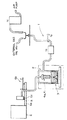
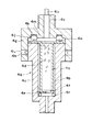
図2は、測定試料自動搬送部7、測定試料挿入計量部8及び加熱部3の断面図であり、図3及び図4は、それぞれ測定試料挿入計量部8のみを示した正面及び側面概略図である。
この図2乃至図4において、測定試料挿入計量部8は、測定試料を載置するサンプル皿3hが挿入されるサンプルケース8aと、サンプルケース8aの蓋8bと、サンプルケース8aを乗せるスライドテーブル8cと、スライドテーブル8cを左右からガイドするガイド8dと、ガイド8dを取付ける台8eと、台8eのベース8fとを有している。そして、台8eとベース8fとの間には、電子天秤6の計量アーム6aに備えられた測定試料計量部6bが設けられており、測定試料計量部6bから天秤シャフト6eが複数出ている。
【0015】
また、ベース8fには、ベースを上下させるためのアーム8gの作用点シャフト8hが左右にあり、アーム8gは支点ブラケット8iに保持されている支点8jを中心に回転運動をする。
すなわち、アーム8gの一方の端は円盤3pの下部に接しており、円盤3pがスクリュー3qの回転により上下することで、アーム8gは支点8jを中心に回転運動を行うことができるようになる。一方、アーム8gの他方の端部には作用点シャフト8hがスライドするように溝8kが設けられており、これによってアーム8gが上下運動をする場合には、スライドテーブル8c上のサンプルケース8aがスライドシャフト8mによって上下運動をすることができる。又、スライドシャフト8mによって上下する場合の回転止めとして回転止めシャフト8nがある。
【0016】
測定試料の質量を測定する際には、まず、モーターYによりスイッチEの位置においてスライドテーブル8cを自動的に器外へ移動させ、この状態でサンプルケース8aの蓋8bを開け、サンプル皿3hをケースの中に入れ、蓋8bを閉める。次に、測定スイッチを押すとモーターYによりスライドテーブル8cが機械内部スイッチFまで搬送されてモーターIによりスイッチGの位置まで下降する。
なお、図4及び5に示されるようにスライドテーブル8cとサンプルケース8aには、天秤シャフト6eが貫通できサンプル皿3hの底面と接することができるよう穴が空いている。そして、前述のように、スクリュー3qの回転により円盤3pが上昇するとベース8fが下降し、それに伴いスライドテーブル8c上のサンプルケース8aがスイッチGの位置まで下降するので、天秤シャフト6eはスライドテーブル8cとサンプルケース8aに設けられた穴を貫通しサンプル皿3hの底面と接することができ、その結果、測定試料計量部6bによってサンプル皿3hの質量を検知し測定することができる。
サンプル皿3hの質量を測定後、スイッチEの位置までスライドテーブル8cは上昇し、スイッチEの位置に到達した後、モーターYによりスライドテーブル8cは自動的に器外へ移動する。
【0017】
次に、この状態でサンプルケース8aの蓋8bを開け、測定試料をサンプル皿3hの中に入れ、蓋8bを閉める。そして、測定スイッチを押すとモーターYによりスライドテーブル8cは器内に搬送されスイッチFの位置で止まり、モーターIによりスイッチGまで下降する。そして、先に述べた機構と同様の機構によって、測定試料計量部6bにより測定試料が載置されたサンプル皿3hの質量を検知し測定することができる。
このような操作を行ない、測定試料の載置前後におけるサンプル皿3hの質量差を求めることによって、測定試料自体の質量が求められる。
【0018】
一方、サンプルケース8aをサンプル皿3hと共に加熱管3aの下部へ移動させるには、図6乃至図9に示すような構成が採られている。すなわち、まず図6に示すように、サンプルケース8aの前方下部には2つの穴7aが空いており、ベース8fが下降すると移動シャフト7bが穴7aに嵌まるため、移動シャフト7bの移動に伴ってサンプルケース8aも移動できるようになる。ここで、移動シャフト7bは移動ブラケット7cに固定されており、移動ブラケット7cは移動ブロック7dに固定されているので、移動ブロック7dはねじ7eの回転により左右に動くことが出来るよう構成されている。
よって、穴7aに移動シャフト7bが嵌まった後、移動ブロック7dの移動によって移動シャフト7bが移動すると、サンプルケース8aもそれに伴って移動し、図7に示すように加熱管3aの下部へ搬送されることとなる。
【0019】
一方、移動ブラケット7cには、カラー7fが2つ付いており、カラー7fの穴7gに加熱部蓋3fのシャフト7hが嵌まっているため、移動ブロック7dの移動により移動ブラケット7cが移動した場合には、それに伴って加熱管蓋3hも移動する。ここで、加熱部蓋3fには、4つの回転体7iがセットされており、回転体7iはレール7j上に乗っている。具体的にレール7jは、図8に示されるような構造となっており、加熱部蓋3fが左右に移動すると、単に横方向だけでなく上下方向にも移動ができるよう設計されている。そして、レール7jが図6に示されるよう設計されていることにより、加熱部蓋3fは、非測定時には加熱管3a下部のシール材3dと接合して加熱管を密着でき、測定時には一旦下降してシール材3dと非密着状態となった後に横方向に移動することができる。
【0020】
上記構成によって測定試料中の水分量を測定する際には、まず、スイッチJまでスライドテーブル8cを上昇させねじ7eを回転させることによって、図7のようにスイッチKまでサンプルケース8aを横移動させる。また、ねじ7eを回転させ移動ブロック7dを左方向に移動させると、加熱部蓋3fも前述のように加熱管の密閉状態を解除した後に左に移動することとなる。なお、蓋8bは図6の(B)に示されるように上部に2つの穴が空いており、サンプルケース8aが左への横移動すると、図7に示すように、この2つ穴にはホールドピン7kが挿入するようになるため、結果として、蓋8bだけがホールドされ、サンプルケース8aのみが加熱部3へと移動する。
【0021】
続いて、図9に示すように、このサンプルケース8aがスイッチKの位置まで搬送されると、加熱管3aの下に設けられた円盤3pがスクリュー3qの回転によりスイッチLまで上昇してくる。そして、サンプルケース8aの中のサンプル皿3hは、円盤3pに取付けてある複数のシャフト3jの突き上げにより加熱管3aの下部開口端より挿入され、下部のシール材3dと接合し図9に示すような状態で加熱管を密閉する。
なお、突き上げ用のシャフト3jは、ねじ3oによって円盤3pに取付けられており、円盤3pはスクリュー3qの回転により上下できるような構造となっている。シャフト3jは、ベースシャフト3kと、ベースシャフト3kの内部をスライドするシャフト軸3mと、ばね3nで構成されている。このシャフト3jはばね3nを有することにより、突き上げ位置の停止精度がばらついていても密閉に必要な荷重がサンプル皿にかかるように設定することができ、また、突き上げ圧力を大きくしたい場合には、ねじ3oのねじ長さを変更することで簡単に圧力を変更することが出来る。
【0022】
また、内外圧力差により外気の進入を遮断し、外気湿気の影響を全く受けることなく測定試料の挿入を可能にするため、加熱管3aを常時ヒーターにより加熱し、且つキャリアガスを上に常時流入しながらサンプル皿3hを挿入することが好ましい。サンプル皿3hの挿入完了後、測定試料の加熱が速やかに開始され、測定試料中の水分及びガス等が気化する。測定試料の加熱が完了した後は、上記と逆の操作が行われ、再び加熱管蓋3fにより、加熱管3aは密閉される。
【0023】
なお、加熱により、気化した測定試料中の水分及びガスは、キャリアガスに携行され、フィルター部4に導入される。そして、このフィルター部4において、キャリアガスに携行される水分以外のガスは、本体4cに充填された活性炭4dにより吸着され、気化した水分のみがキャリアガスに携行され水分吸着部5に導入される。この気化水分量は、次に、水分吸着部5中の吸着剤5cにより吸着され、かかる際における吸着剤5cの増加質量を電子天秤部6によって検知することで、測定試料中の水分量が求められる。
【0024】
図10は、加熱部3及びフィルター部4のホルダー4aの断面図である。この図において、加熱部3は、縦置きにされた中空筒状の加熱管3aを備え、その上部には、2方向のキャリアガス導入口3b及び前記フィルター部4と連絡するキャリアガス流出口3cが設けられている。なお、キャリアガス導入口3bは、必ずしも2方向とする必要はなく1方向でも良いが、前述のように分岐部2によりキャリアガスが分岐された場合には、分岐数に応じて導入口が設けられることになる。また、加熱管3aの下部にはシール材3dが加熱管の底断面3eに沿って取付けられている。ここで、シール材3dの材料としては、耐熱性で且つ水分を吸収しない材料であれば特に制限はないが、優れた耐熱性及び密着性を有し且つ水分の吸収がないという点でフッ素系のゴムであることが好ましい。
更に、非測定時においては、加熱管3aの底は加熱管蓋3fで密閉されている。加熱管蓋3fには、円周上に突起3gが設けられており、接合時には突起3gがシール材3dを突き上げることにより、加熱管を密閉することが可能となる。
一方、測定時においては、加熱管3aの底にはサンプル皿3hが設置され、サンプル皿3hのフランジ部3iがシール材3dを突き上げることにより、非測定時同時に加熱管を密閉することが可能となる。
【0025】
図11は、フィルター部4の断面図である。この図において、フィルター4は、ホルダー4aと挿入部4bとフィルター本体4cとフィルター本体4cに充填された活性炭4dとを有している。フィルター本体4cには、挿入部4bと連通する穴4eが空いており、フィルター本体4cの底にはメッシュ板4fが設置されている。ホルダー4aの外周にはヒーター4qが蒸着されている。ホルダー4a及びヒーター4qの材質は、フィルターの汚れ等の確認を容易にするという点よりガラス製であることが好ましい。なお、高精度の測定を可能とするためには、活性炭を毎日交換することが望ましい。
ホルダー4aの上部には蓋4gがあり、蓋4gの上部にはキャリアガスを通すためのチューブ継ぎ手4o及びチューブ4pが設けられている。なお、ホルダー4aと蓋4gとの取付けによるフィルター本体4cの固定は、図12に示すようにホルダー4a上部にある突起4hと蓋4gの側面に設けられたリード溝4iとを噛合わすことにより行われる。このような固定方法を採用するため、フィルター本体4cの交換を非常に簡単に行うことが出来、また交換時における蓋4g取り外しの際、チューブ4pがねじられることもないのでチューブ4p表面のねじれによる亀裂等による痛みもなく、チューブ4pを蓋4gに取付けたままで、蓋4gをホルダー4aから取り外すことが可能となり、作業性が大幅に改善される。
蓋4gの裏側にはO−リング4jを取付けるための溝4kがある。フィルター本体4cの上部はフランジ形状になっておりこのフランジ部4nと蓋4gの裏の溝4kに取り付けるO−リング4jが密着する。フィルター本体4cの上部にはフランジ部4nと蓋4gの隙間にはメッシュ板4mがある。
【0026】
図13は、水分吸着部5の断面図である。この水分吸着部5は、キャリアガス導入用チューブ5aが接続される台5bと、気化水分を吸着する吸着剤5cが充填されるセル本体5dとを有している。台5bには、チューブ5a装着用のコネクタ部5eと、孔部5fと、円錐状突起部5gとが設けられ、突起部5gがセル本体5dに嵌められる。また、突起部5gを備える台5bは、電子天秤部6における天秤アーム6aに取付けられている。セル本体5dには、突起部5gと嵌合するための凹み5hがあり台5bに取付けられる。更に、セル本体5dには、テフロン製の円盤5iが取付けられており、テフロン製の円盤5iには、キャリアガスがセル本体5dに流入できるように穴が空いている。
【0027】
セル本体5dの上部には、キャップ5jが装着されている。キャップ5jには、水平方向に対称に配置された複数の排出口5kが設けられており、本体上部凹み部5mに設けられた排出口5oと連通するよう構成されている。なお、排出口5oはキャリアガス導入チューブ5aと垂直方向となるように取付けられることが好ましい。キャップ5jとセル本体5dとの取付けは、本体上部凹み部5mとキャップ5jの下部の円錐状の突起部5nとが嵌合することによって行われ、キャップ5jの排出口5kと本体上部凹み部5mの排出口5oとの連通を、キャップ5jを90度回転させることで切り替えることができるので、容易にキャリアガスの流出及び外気の遮断を行うことができる。
【0028】
このように、セル本体5dと台5bもしくはキャップ5jとの取付けが、円錐状の凹凸のみの嵌合だけで可能となり、又チューブ5aは台5bに取付けてあるため、セル本体交換時等に、電子天秤部6に大きな外力を与えることがなく、電子天秤の破損等を防ぐことが出来る。また、セル本体5d及び吸着剤5cの材質としては特に制限はないが、吸着剤の交換時期の判断を容易にするため、セル本体5dはガラス製であることが望ましく、また吸着剤5cは水分補集量によって色が変化するような性質を有するものが好ましい。かかる吸着剤5cの中でもモレキュラーシーブがより好ましく、最も好ましいものとしてはモレキュラーシーブ3Aが挙げられる。またここで、台5b及びキャップ5jの突起部5g及び5nの材質は、取り外しの容易性及び密着性の点でテフロン製であることが好ましい。
【0029】
【発明の効果】
以上説明したように、本発明の水分計用試料計量搬送装置は、測定試料の質量測定手段と測定試料の搬送手段とを備えるよう構成されているため、測定試料の計量及び該試料の加熱管内部への挿入を自動的に且つ一定時間で行なうことができるようになる。このため、外気湿気等の外部環境の影響を受け難い状態で水分量の測定ができ、誤差を生じることなく安定した測定値を得ることが可能になるとともに、測定者の行なう作業を極力削減することができ、また、試料自体の質量を測定するための電子天秤等の設備も不要であり、測定操作の安定性、容易性及び設備の簡略化の点で極めて顕著な効果が達成される。
【0030】
また、本発明においては、試料計量運搬装置の測定試料搬送手段は、非測定時には加熱管蓋により、また測定時にはサンプル皿により加熱管内部を密閉できるよう構成されており、更に測定試料挿入時においても加熱管内部を加圧状態としているので、測定時及び非測定時はもちろんのこと加熱管内部への試料挿入時においても外気の流入を遮断することができるようになる。すなわち、本発明の試料計量運搬装置を用いることで、測定の際に加熱管蓋の開閉作業が不要となり、常時加熱管内部は外気から遮断されているので、測定試料中の気化水分のみを正確に測定することが可能となり、きわめて高精度の気化水分量の測定が可能となる。
【0031】
さらに、本発明においては、磁力式の搬送装置を採用しないため、前述したような、搬送装置周辺を磁化から防止するための対策等は必要なく、また、磁石に影響を及ぼす試料(磁石に引き付けられる成分を含む試料等)等についても、何ら制限なく自由に測定することができ、測定試料の範囲が広がるとともに、測定の際の作業性も大幅に改善されることになる。また、駆動部も直接加熱部へ挿入されることもないため、使用する部材に耐熱性等の制限が課せられることもなく、用途に応じ自由に部材を選択できるようになる。
【図面の簡単な説明】
【図1】水分計の流体系の経路及びブロック図である。
【図2】測定試料自動搬送部及び測定試料挿入計量部の実施例を示す断面図である。
【図3】測定試料挿入計量部の実施例を示す正面概略図である。
【図4】測定試料挿入計量部の実施例を示す側面該略図である。
【図5】本発明のサンプルケース及びスライドテーブルの実施例を示す平面図である。
【図6】測定試料自動搬送部の実施例を示す断面図である(非測定時)。
【図7】測定試料自動搬送部の実施例を示す断面図である(測定試料搬送時)。
【図8】本発明の加熱管蓋の移動状態を示す側面該略図である。
【図9】測定試料自動搬送部の実施例を示す断面図である(測定時)。
【図10】加熱部の実施例を示す断面図である。
【図11】フィルター部の実施例を示す断面図である。
【図12】本発明のフィルター本体の交換方法の説明図である。
【図13】水分吸着部の実施例を示す断面図である。
【符号の説明】
1 コントロール部
2 分岐部
3 加熱部
4 フィルター
5 水分吸着部
6 電子天秤部
7 測定試料自動搬送部
7b 移動シャフト
7d 移動ブロック
7e ねじ
7i 回転体
7j レール
8 測定試料挿入計量部
8a サンプルケース
8b 蓋
8c スライドテーブル
8f ベース[0001]
BACKGROUND OF THE INVENTION
The present invention relates to a sample weighing and conveying apparatus for a moisture meter. In particular, the present invention relates to a sample weighing and conveying apparatus for a moisture meter that enables measurement in a short time and is hardly affected by outside moisture.
[0002]
[Prior art]
Conventionally, the Karl Fischer method (KF method) is widely known as a highly accurate moisture determination method for measuring the amount of water in a solid or liquid. The KF method utilizes the fact that a Karl Fischer reagent containing iodine, sulfur dioxide, pyridine, and methanol as a component reacts quantitatively with water. However, in the measurement of the water content by the KF method, various corrections are required depending on the measurement object, and considerable skill is required to obtain an accurate water content. In addition, there is a problem that special reagents and glass containers are required for the measurement.
[0003]
In order to solve the above problems of the KF method, a heat-drying type moisture meter has been developed. As such a heat-drying type moisture meter, for example, as described in JP-A-7-12696, a gas introduction part for generating a carrier gas, and a carrier gas is introduced from the gas introduction part. A heating unit that heats the object to be measured, a moisture collecting unit that collects vaporized moisture from the carrier gas derived from the heating unit, and an electronic balance unit that detects an increased weight of the moisture collecting unit. Such a thing is mentioned. And such a moisture meter heats the object to be measured, vaporizes the water in the object to be measured, collects and measures the vaporized water, and measures the moisture content of the object to be measured. In order to move the object to be measured to the heating unit, a magnetic conveying device using a rack and a pinion as described in JP-A-7-12700 has been adopted.
[0004]
[Problems to be solved by the invention]
However, the conventional transfer device only moves the measurement sample in the heating tube from the non-heating unit to the measurement unit, and the measurement of the mass of the measurement sample and the insertion of the measurement sample into the heating tube must be made by the measurer. There wasn't. For this reason, there is a variation in the time for the measurement sample to come into contact with the outside air, and in order to insert the sample into the heating tube, it is necessary to open the lid of the horizontal heating tube, which prevents the outside air from flowing into the heating tube. There was a problem that could not be avoided.
Furthermore, the lid of the heating tube has to be structured so that it cannot be easily opened and closed in order to achieve a good hermeticity, has a problem in its operability, and drives the conveying device. Since the part is inserted directly into the heating part, the member is required to have heat resistance, and there is a structural limitation that must use parts that do not generate water due to water absorption, thermal deformation, or heating. It was done.
[0005]
In addition, in the magnetic type transfer device, the surrounding metal is magnetized, so that attention must be paid to the environment around the transfer device. That is, when measuring samples that affect the magnet (samples that contain components attracted to the magnet, etc.), it is difficult to remove the measured sample from the sample pan, or spilled samples are attracted to the magnet in the heating tube. It could be difficult. In addition, since data on a disk (FD) or the like is destroyed by a magnet, it was necessary to be extremely careful when using it around the equipment.
On the other hand, since the magnetic force of the magnet itself also depends on the temperature, replacement is necessary with long-term use, and there is a disadvantage that a magnet having a stronger magnetic force than necessary must be used in order to eliminate the need for replacement.
[0006]
Therefore, the present invention can measure the amount of water in a sample easily in a certain time without being limited by the type of the sample, and is stable and less susceptible to errors caused by the external environment such as external moisture. An object of the present invention is to provide a sample weighing and conveying apparatus for a moisture meter that can obtain a measured value.
[0007]
[Means for Solving the Invention]
In order to achieve the above object, the present invention provides a carrier gas in which moisture in a measurement sample is vaporized by heating in a heating section provided with a heating tube having one end opened vertically so that the opening end is at the bottom. A sample weighing and conveying device for a moisture meter that measures the amount of moisture in a measurement sample by collecting and detecting only this vaporized moisture, and comprising a measurement sample mass measurement means, a measurement sample conveyance means, With
The mass measuring means of the measurement sample has a measurement sample insertion weighing unit and an electronic balance unit provided with a sample case, and the sample case is provided so as to be movable up and down and laterally moved to the lower part of the heating tube and lowered. Is configured to be in contact with the measurement sample weighing unit of the electronic balance unit and to be able to measure the mass of the sample,
The measurement sample transport means is configured such that the sample case, a sample case lid provided on the upper part of the sample case, and a heating tube lid arranged at a lower opening end of the heating tube are interlocked in the horizontal direction. In the non-measurement, the heating tube is sealed with a heating tube lid, and in the measurement, the heating tube can be sealed by the sample pan in the sample case conveyed to the lower part of the heating tube. (Claim 1)
[0008]
In addition, when the measurement is started, the transport means of the measurement sample opens the sample case lid by moving the sample case in the direction of the heating unit, releases the sealed state of the heating tube lid that seals the heating tube, and sets the heating tube. The lower open end is opened under pressure inside the heating tube, and the sample pan in the sample case is pushed up and joined to the lower part of the heating tube so that the inside of the heating tube is sealed. The sample pan is lowered and stored in the sample case, the sample case lid is closed by the return movement of the sample case to the measurement sample insertion weighing unit, and the heating tube lid is moved to the lower part of the heating tube, and heated by the heating tube lid. It is preferable that the lower opening end of the pipe is set to be sealed. (Claim 2)
Furthermore, in the present invention, by using the deformable arm, it is possible to set so that the vertical movement of the sample case and the introduction of the measurement sample into the heating tube can be performed with the same power. (Claim 3)
[0009]
DETAILED DESCRIPTION OF THE INVENTION
The moisture meter sample weighing and conveying apparatus of the present invention includes a measuring sample mass measuring means and a measuring sample conveying means, thereby automatically measuring the measuring sample and inserting the sample into the heating tube. In addition, since the measurement can be performed in a certain time, the moisture content can be measured in a state where it is difficult to be influenced by the external environment such as the outside humidity, and a stable measurement value can be obtained without causing an error.
In the present invention, the measurement sample transporting means of the sample weighing and transporting device is configured so that the inside of the heating tube can be sealed by the heating tube lid when not measuring and by the sample pan at the time of measurement. Since the inside of the heating tube is in a pressurized state, the inflow of outside air into the inside of the heating tube can always be prevented, and only the vaporized water in the measurement sample can be accurately measured.
[0010]
Furthermore, in the present invention, the operation of opening and closing the heating tube lid is not required at the time of measurement, and the operation is simplified because the measurement of the mass of the sample to the heating tube is performed with the same power.
In the present invention, since a magnetic conveying device is not employed, there is no need for measures to prevent the periphery of the conveying device from being magnetized as described above, and a sample that affects the magnet (attracted to the magnet). It is possible to measure a sample including a component to be measured without any limitation. In addition, since the drive unit is not directly inserted into the heating unit, there is no restriction on heat resistance or the like on the member to be used.
[0011]
【Example】
Hereinafter, the present invention will be described in detail based on embodiments shown in the drawings.
FIG. 1 is an embodiment of a sample metering and conveying apparatus for a moisture meter according to the present invention, and is a path and functional block diagram of a fluid system in a moisture meter to which the sample weighing and conveying device of the present invention is applied. In this figure, 1 is a control unit that controls the carrier gas, 2 is a branching unit that divides the controlled carrier gas in two directions, and 3 is a heating unit that introduces the carrier gas from the branching
[0012]
The
[0013]
The branching
[0014]
FIG. 2 is a cross-sectional view of the measurement sample automatic conveyance unit 7, the measurement sample insertion weighing unit 8, and the
2 to 4, the measurement sample insertion and weighing unit 8 includes a
[0015]
In addition, the
That is, one end of the
[0016]
When measuring the mass of the sample to be measured, first, the slide table 8c is automatically moved to the outside by the motor Y at the position of the switch E. In this state, the
As shown in FIGS. 4 and 5, the slide table 8c and the
After measuring the mass of the
[0017]
Next, in this state, the
By performing such an operation and determining the mass difference between the
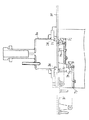
[0018]
On the other hand, in order to move the
Therefore, after the moving
[0019]
On the other hand, since the moving
[0020]
When measuring the amount of water in the measurement sample with the above configuration, first, the slide table 8c is raised to the switch J and the
[0021]
Subsequently, as shown in FIG. 9, when the
The push-up
[0022]
In addition, in order to block the entry of outside air due to the pressure difference between inside and outside, and to allow the measurement sample to be inserted without being affected by outside moisture at all, the
[0023]
The moisture and gas in the measurement sample vaporized by heating are carried by the carrier gas and introduced into the filter unit 4. In the filter unit 4, gases other than moisture carried in the carrier gas are adsorbed by the activated
[0024]
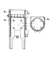
FIG. 10 is a cross-sectional view of the holder 4 a of the
Furthermore, at the time of non-measurement, the bottom of the
On the other hand, at the time of measurement, the
[0025]
FIG. 11 is a cross-sectional view of the filter unit 4. In this figure, the filter 4 includes a holder 4a, an
A lid 4g is provided on the upper portion of the holder 4a, and a tube joint 4o and a tube 4p for allowing carrier gas to pass therethrough are provided on the upper portion of the lid 4g. The
On the back side of the lid 4g, there is a
[0026]
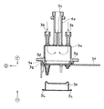
FIG. 13 is a cross-sectional view of the
[0027]
A cap 5j is attached to the upper part of the
[0028]
As described above, the
[0029]
【The invention's effect】
As described above, the sample weighing and conveying apparatus for a moisture meter according to the present invention is configured to include the measurement sample mass measuring means and the measurement sample conveying means, so that the measurement sample is measured and the sample heating tube is heated. The insertion into the inside can be performed automatically and in a fixed time. For this reason, it is possible to measure the amount of moisture in a state that is not easily affected by the external environment such as outside air humidity, and it is possible to obtain a stable measurement value without causing an error, and to reduce the work performed by the measurer as much as possible. In addition, an equipment such as an electronic balance for measuring the mass of the sample itself is not necessary, and a very remarkable effect is achieved in terms of stability and ease of measurement operation and simplification of equipment.
[0030]
In the present invention, the measurement sample transporting means of the sample weighing and transporting device is configured so that the inside of the heating tube can be sealed with a heating tube lid when not measuring, and with a sample pan when measuring, and when the measurement sample is inserted. Since the inside of the heating tube is in a pressurized state, inflow of outside air can be blocked not only during measurement and during non-measurement, but also when the sample is inserted into the heating tube. That is, by using the sample weighing and transporting apparatus of the present invention, it is not necessary to open and close the heating tube lid at the time of measurement, and the inside of the heating tube is always shielded from the outside air, so that only the vaporized moisture in the measurement sample is accurately measured. This makes it possible to measure the amount of vaporized water with extremely high accuracy.
[0031]
Furthermore, in the present invention, since a magnetic conveying device is not adopted, there is no need for measures to prevent the periphery of the conveying device from being magnetized as described above, and a sample (attracting to the magnet) that affects the magnet. The sample including the component to be measured can be measured freely without any limitation, and the range of the measurement sample is widened, and the workability at the time of measurement is greatly improved. Further, since the drive unit is not directly inserted into the heating unit, the member to be used is not limited in heat resistance and the like, and the member can be freely selected according to the application.
[Brief description of the drawings]
FIG. 1 is a path and block diagram of a fluid system of a moisture meter.
FIG. 2 is a cross-sectional view showing an embodiment of a measurement sample automatic transfer unit and a measurement sample insertion and weighing unit.
FIG. 3 is a schematic front view showing an embodiment of a measurement sample insertion weighing unit.
FIG. 4 is a schematic side view showing an embodiment of a measurement sample insertion measuring unit.
FIG. 5 is a plan view showing an example of a sample case and a slide table according to the present invention.
FIG. 6 is a cross-sectional view showing an example of a measurement sample automatic transfer unit (when not measuring).
FIG. 7 is a cross-sectional view showing an embodiment of a measurement sample automatic transfer unit (when a measurement sample is transferred).
FIG. 8 is a schematic side view showing a moving state of the heating tube lid of the present invention.
FIG. 9 is a cross-sectional view showing an example of a measurement sample automatic transfer unit (during measurement).
FIG. 10 is a cross-sectional view showing an example of a heating unit.
FIG. 11 is a cross-sectional view showing an embodiment of a filter unit.
FIG. 12 is an explanatory diagram of a method for replacing a filter body according to the present invention.
FIG. 13 is a cross-sectional view showing an embodiment of a moisture adsorption unit.
[Explanation of symbols]
1 Control part
2 branch
3 Heating part
4 Filter
5 Moisture adsorption part
6 Electronic balance
7 Measurement sample automatic transfer section
7b Moving shaft
7d moving block
7e screw
7i Rotating body
7j rail
8 Measurement sample insertion measuring section
8a Sample case
8b lid
8c slide table
8f base
Claims (3)
前記測定試料の質量測定手段は、サンプルケースを備えた測定試料挿入計量部と電子天秤部とを有し、前記サンプルケースは、上下運動及び加熱管下部への横移動可能に設けられ下降することによって前記電子天秤部の測定試料計量部と接触し、試料の質量を計量可能にするよう構成され、
前記測定試料の搬送手段は、前記サンプルケースと、前記サンプルケースの上部に設けられたサンプルケース蓋と、前記加熱管の下部開口端に配された加熱管蓋とが横方向に連動するよう構成され、非測定時には加熱管を加熱管蓋により密閉し、測定時には加熱管の下部へ搬送されたサンプルケース内のサンプル皿により加熱管が密閉可能となるようにした水分計用試料計量搬送装置。A heating tube with one open end is placed vertically so that the open end is at the bottom. Water in the measurement sample is vaporized by heating and carried with a carrier gas. Only the vaporized water is collected and detected. It is a sample weighing and conveying device for a moisture meter that measures the amount of moisture in the measurement sample, and comprises a measurement sample mass measurement means and a measurement sample conveyance means,
The mass measuring means of the measurement sample has a measurement sample insertion weighing unit and an electronic balance unit provided with a sample case, and the sample case is provided so as to be movable up and down and laterally moved to the lower part of the heating tube and lowered. Is configured to be in contact with the measurement sample weighing unit of the electronic balance unit and to be able to measure the mass of the sample,
The measurement sample transport means is configured such that the sample case, a sample case lid provided on the top of the sample case, and a heating tube lid arranged at a lower opening end of the heating tube are interlocked in the horizontal direction. A sample metering and conveying device for a moisture meter, wherein the heating tube is sealed with a heating tube lid when not measuring, and the heating tube can be sealed with a sample pan in the sample case conveyed to the lower part of the heating tube when measuring.
Priority Applications (1)
| Application Number | Priority Date | Filing Date | Title |
|---|---|---|---|
| JP11467097A JP3761663B2 (en) | 1997-05-02 | 1997-05-02 | Sample weighing and conveying device for moisture meter |
Applications Claiming Priority (1)
| Application Number | Priority Date | Filing Date | Title |
|---|---|---|---|
| JP11467097A JP3761663B2 (en) | 1997-05-02 | 1997-05-02 | Sample weighing and conveying device for moisture meter |
Publications (2)
| Publication Number | Publication Date |
|---|---|
| JPH10307101A JPH10307101A (en) | 1998-11-17 |
| JP3761663B2 true JP3761663B2 (en) | 2006-03-29 |
Family
ID=14643670
Family Applications (1)
| Application Number | Title | Priority Date | Filing Date |
|---|---|---|---|
| JP11467097A Expired - Lifetime JP3761663B2 (en) | 1997-05-02 | 1997-05-02 | Sample weighing and conveying device for moisture meter |
Country Status (1)
| Country | Link |
|---|---|
| JP (1) | JP3761663B2 (en) |
Families Citing this family (1)
| Publication number | Priority date | Publication date | Assignee | Title |
|---|---|---|---|---|
| JP4994104B2 (en) * | 2007-05-10 | 2012-08-08 | 昭和シェル石油株式会社 | Vaporizer used to measure the content of petroleum hydrocarbon components in soil |
-
1997
- 1997-05-02 JP JP11467097A patent/JP3761663B2/en not_active Expired - Lifetime
Also Published As
| Publication number | Publication date |
|---|---|
| JPH10307101A (en) | 1998-11-17 |
Similar Documents
| Publication | Publication Date | Title |
|---|---|---|
| US5932482A (en) | Headspace vial apparatus and method | |
| US4937048A (en) | Carrier transporting apparatus and carrier container for use in an immunological analysis | |
| EP0246632B1 (en) | Pipetting device having an automatic mechanism for replacing nozzle tips | |
| EP1054256B1 (en) | Adaptor for desorbing sampling tubes, assembly comprising a gas chromatograph and the adaptor, and a kit of parts for forming such an assembly | |
| US4705667A (en) | Analyzing apparatus for measuring liquid or gaseous samples | |
| US6279387B1 (en) | Moisture meter, electronic weighing machine for moisture meter, filter for moisture meter, and moisture adsorption unit for moisture meter | |
| EP1273920A2 (en) | Apparatus for analysis with means for automatic introduction of reference fluid for the apparatus | |
| CN104458999B (en) | Organic substance automatic analyzer | |
| CN221765363U (en) | A liquid level detection and sampling device for liquid chromatography mobile phase | |
| JP3761663B2 (en) | Sample weighing and conveying device for moisture meter | |
| US20070137320A1 (en) | Method For The Preparation Of Samples For An Analyzer And Sampling Station Therefor | |
| CN110404283B (en) | Rotary evaporator capable of accurately and quantitatively concentrating multiple samples at one time | |
| JP2588864Y2 (en) | Heating device for moisture meter | |
| JP3779419B2 (en) | Electronic balance for moisture meter | |
| JP3779420B2 (en) | Moisture meter | |
| CN110579551B (en) | Equipment and transfer container for headspace sampling | |
| CN110404596B (en) | A detection device | |
| KR19990023836A (en) | Heating device to vaporize the sample by heating | |
| JPS63286770A (en) | Dispensing nozzle and fixed volume dispensing pump for liquid analyzer for medical inspection | |
| JPH10307100A (en) | Moisture adsorbing device for moisture meter | |
| CN111579457B (en) | Device and method for simply and conveniently testing formaldehyde removal performance of material | |
| JP2001330596A (en) | Assembly for detaching sampling tube, adapter and sampling tube clearly intended for assembly and component kit for forming assembly | |
| JPH10307099A (en) | Filter for moisture meter | |
| JPH10307097A (en) | Moisture meter | |
| CN115856178B (en) | Headspace solid-phase microextraction sampling device and method |
Legal Events
| Date | Code | Title | Description |
|---|---|---|---|
| A621 | Written request for application examination |
Free format text: JAPANESE INTERMEDIATE CODE: A621 Effective date: 20040220 |
|
| A977 | Report on retrieval |
Free format text: JAPANESE INTERMEDIATE CODE: A971007 Effective date: 20051219 |
|
| TRDD | Decision of grant or rejection written | ||
| A01 | Written decision to grant a patent or to grant a registration (utility model) |
Free format text: JAPANESE INTERMEDIATE CODE: A01 Effective date: 20060104 |
|
| A61 | First payment of annual fees (during grant procedure) |
Free format text: JAPANESE INTERMEDIATE CODE: A61 Effective date: 20060111 |
|
| R150 | Certificate of patent or registration of utility model |
Free format text: JAPANESE INTERMEDIATE CODE: R150 |
|
| FPAY | Renewal fee payment (event date is renewal date of database) |
Free format text: PAYMENT UNTIL: 20100120 Year of fee payment: 4 |
|
| FPAY | Renewal fee payment (event date is renewal date of database) |
Free format text: PAYMENT UNTIL: 20110120 Year of fee payment: 5 |
|
| FPAY | Renewal fee payment (event date is renewal date of database) |
Free format text: PAYMENT UNTIL: 20120120 Year of fee payment: 6 |
|
| FPAY | Renewal fee payment (event date is renewal date of database) |
Free format text: PAYMENT UNTIL: 20130120 Year of fee payment: 7 |
|
| FPAY | Renewal fee payment (event date is renewal date of database) |
Free format text: PAYMENT UNTIL: 20140120 Year of fee payment: 8 |
|
| R250 | Receipt of annual fees |
Free format text: JAPANESE INTERMEDIATE CODE: R250 |
|
| R250 | Receipt of annual fees |
Free format text: JAPANESE INTERMEDIATE CODE: R250 |
|
| R250 | Receipt of annual fees |
Free format text: JAPANESE INTERMEDIATE CODE: R250 |
|
| R250 | Receipt of annual fees |
Free format text: JAPANESE INTERMEDIATE CODE: R250 |
|
| EXPY | Cancellation because of completion of term |