JP3761499B2 - Robot hand in automatic cartridge loading device - Google Patents
Robot hand in automatic cartridge loading device Download PDFInfo
- Publication number
- JP3761499B2 JP3761499B2 JP2002207260A JP2002207260A JP3761499B2 JP 3761499 B2 JP3761499 B2 JP 3761499B2 JP 2002207260 A JP2002207260 A JP 2002207260A JP 2002207260 A JP2002207260 A JP 2002207260A JP 3761499 B2 JP3761499 B2 JP 3761499B2
- Authority
- JP
- Japan
- Prior art keywords
- cartridge
- hook
- picker
- robot hand
- mounter
- Prior art date
- Legal status (The legal status is an assumption and is not a legal conclusion. Google has not performed a legal analysis and makes no representation as to the accuracy of the status listed.)
- Expired - Fee Related
Links
Images


Classifications
-
- G—PHYSICS
- G11—INFORMATION STORAGE
- G11B—INFORMATION STORAGE BASED ON RELATIVE MOVEMENT BETWEEN RECORD CARRIER AND TRANSDUCER
- G11B15/00—Driving, starting or stopping record carriers of filamentary or web form; Driving both such record carriers and heads; Guiding such record carriers or containers therefor; Control thereof; Control of operating function
- G11B15/675—Guiding containers, e.g. loading, ejecting cassettes
- G11B15/68—Automatic cassette changing arrangements; automatic tape changing arrangements
- G11B15/682—Automatic cassette changing arrangements; automatic tape changing arrangements with fixed magazines having fixed cassette storage cells, e.g. in racks
- G11B15/6835—Automatic cassette changing arrangements; automatic tape changing arrangements with fixed magazines having fixed cassette storage cells, e.g. in racks the cassettes being transferred to a fixed recorder or player using a moving carriage
-
- G—PHYSICS
- G11—INFORMATION STORAGE
- G11B—INFORMATION STORAGE BASED ON RELATIVE MOVEMENT BETWEEN RECORD CARRIER AND TRANSDUCER
- G11B17/00—Guiding record carriers not specifically of filamentary or web form, or of supports therefor
- G11B17/22—Guiding record carriers not specifically of filamentary or web form, or of supports therefor from random access magazine of disc records
- G11B17/225—Guiding record carriers not specifically of filamentary or web form, or of supports therefor from random access magazine of disc records wherein the disks are transferred from a fixed magazine to a fixed playing unit using a moving carriage
Description
【0001】
【発明の属する技術分野】
本発明は、カートリッジ自動装填装置におけるロボットハンドに関し、特に、コンピュータ等にネットワークを介して接続され、磁気テープ等を内蔵するカートリッジを装置内で移動させ、このカートリッジに対して情報の記録、再生を行うと共に、装置内でカートリッジの保管を行うカートリッジ自動装填装置におけるロボットハンドに関する。
【0002】
【従来の技術】
従来、コンピュータシステムにおける情報量の増大に伴い、大容量の情報を保管するための情報記憶装置として、磁気テープ(光磁気ディスク、デジタルビデオディスク等)を内蔵するカートリッジ式記録媒体(以後単にカートリッジと言う)を用いたライブラリ装置等のカートリッジ自動装填装置がある。このような装置には、カートリッジ式記録媒体に対してデータの記録、或いは再生を行う記録再生装置と、この媒体を収納可能な複数の棚、及び記録媒体であるカートリッジの搬送を行うロボットハンドが内蔵されている。
【0003】
ロボットハンドは、記録再生装置及び棚に対するカートリッジの挿入/引抜き、及びカートリッジの搬送を自動的に行うために、装置内の3次元の方向全てに移動可能である。また、ロボットハンドは、カートリッジの搬送時には、記録再生装置又は棚からカートリッジを取り出してロボット内に一時格納し、次にこれを搬送し、その後にカートリッジを目的の記録再生装置又は棚に投入するという動作を行う。ロボットハンドがカートリッジをハンドリングするハンド機構は、ピッカと呼ばれる。このピッカがカートリッジをハンドリングする方法としては、カートリッジにある溝等にフックを引っ掛けた状態で把持する方法、或いはカートリッジ自体を把持する方法がある。
【0004】
(1)そして、磁気テープカートリッジを用いたライブラリ装置のロボットハンドでは、ピッカの前後動作とカートリッジを把持するフックの開閉動作について、それぞれその動作専用の機構とその駆動源を持つものや、ピッカの前後動作とフックの開閉動作については1つの駆動源にて行うことができるように構成されたものが一般的である。また、カートリッジを記録再生装置およびカートリッジ収納棚へ挿入する際に、カートリッジを記録再生装置又はカートリッジ収納棚へ挿入する役割を持つ、マウンタと呼ばれる機構を装備するものがあるが、このマウンタを動作させるにも、その動作専用の駆動源を持つものが一般的である。ところが、このマウンタの動作とピッカの前後動作とフックの開閉動作の3つの動作を、1つの駆動源にて行うことができるように構成されたものはまだない。
【0005】
(2)ところで、このようなライブラリ装置に使用されるカートリッジは、メインフレーム市場における情報記憶装置等で使用している1/2インチ カートリッジと、オープン市場における情報記憶装置等で使用しているLTO カートリッジやDLT/S−DLT カートリッジの、大きく分けて3種類の磁気テープカートリッジが存在している。カートリッジの種類が異なると、カートリッジ自体の大きさが異なる。また、同じカートリッジを使用する記録再生装置であっても、記録再生装置の形式(製造業者の違い等)によって記録再生装置に対するカートリッジの押し込み量が異なっている。
【0006】
一方、ライブラリ装置などに搭載する記録再生装置を特定の製造業者のものとし、記録再生装置とカートリッジ収納棚へのカートリッジの押し込み量を一定にそろえ、ハンドにはマウンタは存在しているがハンド内のピッカに固定され、それ自体ではマウンタは稼動しないものとした、ピッカにおける記録再生装置をカートリッジ収納棚に対するカートリッジの引き抜き/押し込みの両動作については、ピッカの移動量を一定(異なる移動量には対応不可)としたロボットハンド機構がある。
【0008】
【発明が解決しようとする課題】
しかしながら、従来の技術で説明した(1)については、次の懸念がある。即ち、ピッカの前後動作とフックの開閉動作については1つの駆動源(モータ/ソレノイドなど)にて行うことができるように構成された装置であっても、他にも別に駆動源の数が多いので、制御回路も複雑となりコストアップとなってしまう。そして、駆動源が増えると、その駆動源の実装スペースを確保するために他の機構部の実装スペースを圧縮してしまい、ロボットの構造の複雑化/部品点数の増加をまねき、コストアップとなってしまうという問題があった。
【0009】
また、ピッカの前後動作とフックの開閉動作を一つの駆動源にて行う機構では、フックを閉じるタイミングが常に一定であった。このため、装置および他の機構部等の部品寸法公差バラツキの累積によって、ロボットハンドと記録再生装置又はカートリッジ収納棚の間の距離が装置によって異なった場合、カートリッジに対してフックが閉じるべき最適な位置で閉じることができないという現象が発生する。そして、設定していたロボットハンドと記録再生装置又はカートリッジ収納棚との間の距離が長かった場合、最適位置の手前でフックが閉じてしまい、フックがカートリッジを掴めない不具合が生じる。逆に、ロボットハンドと記録再生装置又はカートリッジ収納棚との間の距離が短かった場合、フックが閉じなければならない位置に到達しているのにフックが閉じず、フックがカートリッジを掴めないなどの障害が発生してしまう。
【0011】
しかしながら、従来の技術で説明した(2)については、次の懸念がある。即ち、ライブラリ装置等のカートリッジ自動装填装置において、使用するカートリッジの種類や記録再生装置の形式を特定することは、近年、急速に規模を拡大してきているオープン市場向けの装置においては、ユーザのニーズに対応することが出来ない恐れがあり、ビジネスチャンスを逃すことに繋がりかねない。例えば、1台のライブラリ装置やカートリッジ自動装填装置に、使用するカートリッジの種類は1種類で良いが搭載する記録再生装置は複数の形式や製造業者の記録再生装置を搭載したいという要望や、同じく1台のライブラリ装置やカートリッジ自動装填装置に、LTO 用の記録再生装置とS−DLT 用の記録再生装置とを混在して搭載したいという要望には決して対応することができない。また、オープン市場における、LTO とDLT/S−DLT の、どちらのカートリッジが規模を拡大し、どちらが衰退していくのか全く分からない近年の状況においては、なおさら、使用するカートリッジの種類や記録再生装置の形式を特定することは避けたい。
【0013】
そこで、本発明の目的は、前記従来のライブラリ装置におけるロボットハンドにおける課題を解決し、廉価で信頼性の高いカートリッジ自動装填装置におけるロボットハンドを提供することにある。
【0014】
【課題を解決するための手段】
前記目的を達成する本発明によれば、ハンド機構の前後動作とフックの開閉動作、および、マウンタ動作を一つの駆動源にて行うことができ、かつ、ハンド機構と記録再生装置間の距離やハンド機構とカートリッジ収納棚との間の距離が、装置及び他の機構部等の部品寸法のバラツキの累積によって、装置毎に異なった場合でも、常に最適の位置でフックの閉じる動作を行うことができ、カートリッジを確実にフックにて把持することができ、さらに情報記憶装置用の3種類の磁気テープカートリッジに対するハンドリングおよび使用カートリッジが異なる記録再生装置や、様々な製造業者の記録再生装置に対応可能であるように構成されたカートリッジ自動装填装置におけるロボットハンドが提供される。
【0020】
また、信頼性が高く、少ない実装スペース/簡素な構造で、かつ、小型化/廉価に適し、使用するカートリッジや搭載する記録再生装置の種類/製造業者を選ばないカートリッジ自動装填装置におけるロボットハンドが達成される。
【0022】
【発明の実施の形態】
以下添付図面を用いて本発明の実施形態を具体的な実施例に基づいて詳細に説明する。
【0023】
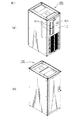
図1(a)は本発明が適用される磁気テープライブラリ装置100を正面側から見たものであり、(b)は背面側から見たものである。ライブラリ装置100の正面パネルには、磁気テープが内蔵されたカートリッジを複数個収納するマガジンを、このライブラリ装置100に出し入れするための媒体アクセスポート101がある。この実施例のライブラリ装置100には媒体アクセスポート101は2箇所あり、それぞれの媒体アクセスポート101からマガジンを出し入れすることができる。また、ライブラリ装置100の内部に収納されたカートリッジの交換や内部装置の点検は、扉102を開けることによっても行うことができる。そして、ライブラリ装置100の扉102にはオペレータパネル103が設けられており、装置に内蔵されたカートリッジの選択等の操作をこのオペレータパネル103を通じて行うこともできる。
【0024】
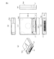
図2(a)は図1(a)に示すライブラリ装置100の内部構成を示すものである。また図2(b)は(a)のライブラリ装置100の内部構成を上から見たものである。ライブラリ装置100の内部には、カートリッジ15に対して記録再生を行う記録再生装置50と、カートリッジ15を複数個収納する棚60が複数ある。この実施例では、記録再生装置50は横方向に2列並べられ、縦方向に4個並べられており、合計8台装備されている。そして、この記録再生装置50とカートリッジ15の収納棚60の間でカートリッジ15を搬送するためのロボット70が装置の中に設けられている。
【0025】
このようなライブラリ装置100は、コンピュータ、サーバ、パーソナルコンピュータにネットワークを介して接続され、各装置からのアクセスに応じて、カートリッジに情報を記録し、またカートリッジからの再生を行う。そのために、複数のカートリッジをライブラリ装置100内の棚60に収納している。更に、カートリッジの追加が必要になった場合には、マガジン40を利用して媒体アクセスポート101を介して、マガジン40に収納されたカートリッジをロボット70により装置内の棚60に搬送することにより、カートリッジがライブラリ装置100内に投入される。また、ライブラリ装置100内のカートリッジを取り出す場合には、ライブラリ装置100の棚60からマガジン40にカートリッジをロボット70により移動し、マガジン40を利用して、媒体アクセスポート101からカートリッジを取り出す。
【0026】
前述のロボット70は、ライブラリ装置100の中を3次元的に移動することができる。即ち、図2(a),(b)に矢印A,B,及びCで示すように、ロボット70は、装置の上下方向への移動(矢印A)と、装置の幅方向への往復移動(矢印B)、及び取付軸に対する回転を行うことができる。これにより、ロボット70は、各棚60、記録再生装置50、及びマガジン40の間で、カートリッジを自由に搬送、移動することができる。
【0027】
図3はライブラリ装置100で使用されるカートリッジ15の1つの種類であるLTO媒体15Aを示すものであり、(a)はLTO媒体15Aを背面側から見たもの、(b)はLTO媒体15Aの正面図、(c)はLTO媒体15Aの平面図、(d)はLTO媒体15Aの背面図、(e)はLTO媒体15Aの側面図である。LTO媒体15Aの外寸は、図示のように、幅が105.4mm、奥行きが102mm、高さが21.5mmである。
【0028】
LTO媒体15Aには、その背面側の両側面にはロボットハンドによって把持される凹部41が設けられている。また、背面にはこのカートリッジ15を識別するためのバーコードラベル44が貼付されている。
【0029】
図4はライブラリ装置100で使用されるカートリッジ15のもう1つの種類であるDLT媒体15Bを示すものであり、(a)はDLT媒体15Bを背面側から見たもの、(b)はDLT媒体15Bの正面図、(c)はDLT媒体15Bの平面図、(d)はDLT媒体15Bの背面図、(e)はDLT媒体15Bの側面図である。DLT媒体15Bの外寸は、図示のように、幅が105.4mm、奥行きが105.8mm、高さが25.4mmである。
【0030】
DLT媒体15Bにも、その背面側の両側面には凹部41が設けられている。ロボットハンドはこの凹部41でカートリッジ15Bを把持する。また、背面にはこのカートリッジ15Bを識別するためのバーコードラベル44が貼付されている。
【0031】
磁気テープカートリッジを使用するライブラリ装置では一般的に、LTO媒体15AやDLT媒体15Bのカートリッジの背面側にバーコードラベル44が貼付されている。このバーコードラベル44には、媒体に記録されているデータの情報が書かれており、ロボットハンドに内蔵されたCCDカメラユニットや、バーコードリーダユニット等によって、バーコードラベルに記載されたバーコードを読み取り、その情報を使ってバックアップ作業を行っている。
【0032】
ここで、本発明のライブラリ装置100におけるロボットハンドが、カートリッジを把持してロボットハンドに一時的に保持する動作、搬送後にカートリッジを目的の収納棚(又は記録再生装置)に挿入する動作について説明するが、ロボットハンドの動作を分かり易くするために、ロボットハンド内の細部の動作を、(1)ロボットハンドに内蔵されたピッカの前後動作とフックの開閉動作を1つの駆動源にて行う機構、(2)フックを常に最適の位置で止めて、フックの閉じる動作を最適位置で行う機構、及び、(3)様々な種類のカートリッジの収納棚(又は記録再生装置)への押し込み量を適切にするマウンタ機構を含めたロボットハンドの総合動作、の順に順を追って説明する。なお、各図に於いて同じ部位は同じ番号で表している。
【0033】
(1)〔ピッカの前後動作とフックの開閉動作を1つの駆動源にて行う機構〕
図5(a)は本発明の一実施例のロボットハンド30を正面右側から見たものであり、図5(b)はこのロボットハンド30を正面左側から見たものである。ロボットハンド30には、ベース13、このベース13の上に取り付けられた2枚のサイドプレート32、及びサイドプレート32にマウントされた上部ハウジング31が設けられており、ベース13と上部ハウジング31の間に後述するピッカが設けられている。更に、上部ハウジング31の上には、ロボットハンド30における唯一の駆動源であるモータ1がマウントされている。このモータ1の駆動力は減速機構20によって使用に適した力に変換されて内部のピッカに伝達され、ピッカが移動する。
【0034】
図6(a)は図5(a)に示したロボットハンド30のベース13から上部ハウジング31を取り外して示すものである。また、図6(b)は図6(a)に示した上部ハウジング31を底面側から見たものである。ベース13の中央部には、サイドプレート32に平行な方向に2本のスライドシャフト11が設けられている。スライドシャフト11は前述のピッカの前後スライド動作の軌道となるものである。ピッカはこの図では符号4で示されている。
【0035】
ピッカ4は、後述するフックやピン等を含んでおり、スライドシャフト11に沿って移動して、カートリッジを収納棚又は記録再生装置から引き出してこのベース13の上に一時保持する動作、及び一時保持したカートリッジを収納棚又は記録再生装置に挿入する機能を有するものである。また、図6(b)に示すように、上部ハウジング31の裏面側には、上部ハウジング31の長手方向に駆動ベルト3が設けられている。駆動ベルト3は、減速機構2により変換されたモータ1の駆動力を前述のピッカ4に伝えるものである。
【0036】
なお、以後の説明において、ピッカ4がスライドシャフト11に沿って移動する動作のうち、ピッカ4がカートリッジの収納棚に近づく動作を、ピッカ4が進む、或いは前進すると表現し、ピッカ4がカートリッジ収納棚から離れる動作をピッカ4が後退する、或いは戻ると表現する。また、モータ1は、或る方向に回転した時にピッカ4が前進し、その逆方向に回転した時にピッカ4が後退するものとする。
【0037】
図7(a)は図6(a)に示したベース13からサイドプレート32とアクチュエータ16を取り去った状態を示すものであり、図7(b)は図7(a)のベース13に取り付けられたガイド14のみの詳細を示すものであり、図7(c)は図7(a)のベース13を底面側から見たものである。
【0038】
ピッカ4の内部には、ピッカ4の軌道となるスライドシャフト11に直交する方向に2本のスライドシャフト8が設けられており、このスライドシャフト8には、カートリッジを把持する(引っ掛ける)ための指(爪)であるフック6が取り付けられている。スライドシャフト8はフック6が開閉動作を行う際の軌道となるものである。また、フック6のスライドシャフト8の近傍には、フック6に開閉動作を行わせるピン7が設けられている。このピン7は、ピッカ4が移動した時にベース13に取り付けられたガイド14に係合し、このガイド14の側面を摺動することにより、フック6に開閉動作を行わせるようになっている。
【0039】
ガイド14は、板ばね14aで接続された2つの部材14A,14Bから構成されており、螺子26によってベース13に、その裏面側から取り付けられている。従って、ガイド14の2つの部材14A,14Bは、ベース13の表側から押されると、板ばね14aが撓んでベース13の裏側に移動するようになっている。また、ガイド14の2つの部材14A,14Bには、それぞれテーパ部14b、ストレート部14c、傾斜部14d、及び上面14eがある。
【0040】
図8(a)は図7(a)に示したピッカ4のみを抜き出して示すものであり、図6(b)に示した駆動ベルト3との接続を説明するものである。また、図8(b)はピッカ4を底面側から見たものである。ピッカ4の上面には、駆動ベルト3と結合する連結部5が設けられている。駆動ベルト3はこの実施例では内歯ベルトであり、この駆動ベルト3を連結部5に固定する連結板5aには内歯と同じ間隔のスリット5bが設けられている。連結板5aはこのスリット5bに駆動ベルト3の内歯を挿入した状態で螺子26によって連結部5に取り付けられる。この結果、駆動ベルト3の移動に伴ってピッカ4が移動する。
【0041】
ピッカ4の底面側には、ピッカ4の移動方向と直交する方向に2本のスライドシャフト8が設けられており、このスライドシャフト8を摺動可能にフック6が取り付けられている。フック6とフック6を動作させるピン7については後述する。また、ピッカ4の下部には4個の連結部12が設けられている。この連結部12には、図7(a)に示したベース13の上のスライドシャフト11が挿通される。
【0042】
図9(a)は図8(a)に示したピッカ4の内部にあるフック6とスライドシャフト8との関係を示すものである。フック6は、スライドシャフト8を軌道として摺動する矩形状のフレーム6aの、外側のフレーム6bが延長された先端部が内側に折り曲げられて形成されたものである。そして、外側のフレーム6bには、2本のピン7が外側のフレーム6bを貫通して植設されている。この図における符号aは、フック6の移動方向を示すものである。
【0043】
また、2つの矩形状のフレーム6aは2組のばね10によって互いに近づく方向に引っ張られている。一方、スライドシャフト8には、フック6がスライドシャフト8に沿って閉じた時の停止位置を決めるためのストッパ9が設けられている。よって、ばね10に引っ張られた2つの矩形状フレーム6aは、通常状態ではこのストッパ9の位置で停止している。ばね10は、矩形状のフレーム6aが現在の位置から外側に移動した時に引っ張り、フレーム6aをストッパ9の位置に戻すように作用する。図9(b)は、図9(a)に示したフック6、ピン7、スライドシャフト8、及びばね10の、ベース13上の位置を示すものであり、図7(a)からピッカ4のカバーを消去した状態を示すものである。
【0044】
ここで、以上のように構成された本発明におけるピッカ4の前後動作とフック6の開閉動作を、1つの駆動源であるモータ1を用いて行う構成の詳細な説明を行う。
【0045】
図10(a)は図9(b)からベース13を除去してフック6とガイド14との関係を示すものであり、図10(b)はこのフック6とガイド14の位置関係を、ベース13の底面側から見たものである。これらの状態は、フック6の動作前の状態を示しており、フック6は、ばね10の付勢力により閉じている状態であり、ストッパ9に当接して静止している。
【0046】
図5から図9で説明したように、モータ1がピッカ4を前進させる方向に回転を開始すると、モータ1の駆動力は減速機構2および駆動ベルト3を介して連結部5に伝わり、駆動ベルト3の移動に伴ってピッカ4がスライドシャフト11に沿って動き出す。この状態は、図10(b)において、フック6、ピン7、スライドシャフト8、及びばね10が図の左側に移動する状態である。
【0047】
図11(a)はピッカ4の移動によりフック6を動作させるピン7がガイド14のテーパ部14bに係合した状態を示すものである。図の左側にはこのピッカ4が把持しようとするカートリッジ15が示されている。ピッカ4が更に進むと、ピン7はテーパ部14bに沿って移動することとなり、この結果、閉じていたフック6は徐々に開いていくことになる。ピッカ4が更に進むと、ピン7がガイド14のテーパ部14bを過ぎ、ストレート部14cに到達する。この状態が図11(b)に示す状態である。この状態からは、フック6の開き動作も停止し、この時点でのフック6の開き量を維持しながら移動して行く。
【0048】
この実施例では、この前後の2本のピン7により、フック6の開閉のタイミングを調整している。この2本のピン7の距離は、ガイド14の長さ等により決定される。
【0049】
モータ1の回転によりピッカ4が更に進むと、図12(a)に示すように、2つのピン7のうちの前側のピンがガイド14から外れる。しかし、後側のピン7は未だガイド14のストレート部14cに接触しているため、フック6は閉じることなく、開いたままの状態で移動を続ける。
【0050】
モータ1の回転によりピッカ4が更に進むと、図12(b)に示すように、2つのピン7のうちの後側のピンもガイド14から外れる。この瞬間、フック6はばね10の付勢力により一瞬にして閉じる。そして、閉じたフック6はカートリッジ15の両側に設けられている凹部41に入り込み、カートリッジ15を把持する。
【0051】
この場合、フック6を閉じると共に、カートリッジ15の凹部に嵌まり込むようにするためには、ピッカ4、収納棚、カートリッジ15の製造精度を高く保つ必要がある。そして、製造精度を高くすると製造コストのアップにつながる。そのために、フック6と凹部41が嵌まり込む位置より、更にピッカ4が前進した位置でフック6を閉じるようにしておき、フック6が閉じた後にピッカ4を後退させることにより、フック6と凹部41が嵌合するようにしておく。これにより、製造精度をさほど高くしなくても、確実にフック6と凹部41とを嵌合させることができる。
【0052】
図13は、この時の状態を、図7(a)と同じ視点から見たものであり、ピッカ4がカートリッジ15を把持した状態が示されている。
【0053】
以上の動作が、ピッカ4の「往路」におけるフック6の開閉動作(フック6とガイド14の関連動作)のメカニズムであり、いわゆる、ピッカ4が収納棚又は記録再生装置にあるカートリッジ15を把持し、カートリッジ収納棚からカートリッジ15を抜き取るための動作である。この後、ピッカ4は、把持したカートリッジ15をベース13の上に引き込む動作、即ち、「復路」の動作を行う。このピッカ4の「復路」の動作については、図14により、フック6、ピン7、及びガイド14のみの動作について説明する。
【0054】
図14(a)は、図13を右手前方向から見た時のフック6、ピン7、及びガイド14の位置を示すものである。この状態からモータがピッカ4を後退させる方向に回転すると、ピッカ4がベースに戻る動作を開始する。ピッカ4が後退を始めると、図14(b)に示すように、後側のピン7がガイド14のテーパ部14dに当接した状態で図の右側に移動する。すると、ガイド14は図の矢印方向に押し下げられる。
【0055】
これは、図7で説明したように、ガイド14は図の矢印方向へは弾性変形可能に作られているからである。即ち、ガイド14の板ばね14a中心は螺子26によってベース13に固定されており、一方、フック6やピン7はピッカ4に固定され、更にピッカ4はスライドシャフト11によって上下方向は移動不可なように固定されているので、ガイド14が押し下げられるのである。
【0056】
図14(b)の状態から更にピッカ4が後退すると、図14(c)に示すように、ガイド14はピン7によって更に押し下げられ、ピン7はガイド14の上面14eの上を摺動することになる。このように、ピッカ4の後退により、ガイド14はピッカ4の軌道を妨げることなく自動的に退避する形になる。
【0057】
モータ1が回転してピッカ4が更に後退すると、後側のピン7がガイド14のテーパ部14bの位置になるが、前側のピン7はまだガイド14の上面14eの上にあるので、ガイド14は押し下げられたままである。一方、ピッカ4が図11(a)に示した位置まで後退すると、ピン7が2つともガイド14の上面14eから外れるので、ピン7によるガイド14の押し付けが解除され、下方に押し付けられていたガイド14は板ばね14aの持つ弾性力により元の位置に復帰する。この状態が図14(d)である。
【0058】
モータ1の回転によりピッカ4は更に後退し、図7(a)に示した最初の待機状態位置に戻り、ピッカ4は往復動作を終了する。ピッカ4が往復動作を終了した状態が図15であり、ピッカ4はカートリッジ15をベース13の上に一時的に保持する。すなわち、フック6とカートリッジ15の凹部41が嵌合した状態で、カートリッジ15をベース13上に保持するため、ロボットハンドを移動させても落ちることはない。
【0059】
このように、本発明では、ピッカ4を前述のように構成したので、ピッカ4の前後動作とフック6の開閉動作を1つのモータ1で行うことが可能となる。また、フック6の開閉動作を、スライドシャフト8を用いた直線運動としたことにより、1/2インチ カートリッジと、LTO カートリッジやDLT/S−DLT カートリッジの、幅寸法の異なる3種類の磁気テープカートリッジを掴むことが可能となる。
【0060】
ところで、以上説明した構成では、ロボットハンド30がフック6を閉じる位置を、カートリッジ15に対して常にある一定の位置とする必要がある。従って、ロボットハンド30の位置制御を正確に行うことが必要となる。
【0061】
ところが、ロボットハンド30に正確な位置制御を行うことができない場合は、装置および他機構部等の部品寸法公差バラツキの累積によってロボットハンド30と記録再生装置50との間の距離や、ロボットハンド30とカートリッジの収納マガジン60との間の距離が装置によって異なった場合、カートリッジ15に対してフック6が閉じるべき最適な位置で閉じることができないという現象が発生する。即ち、設定していたロボットハンド30と記録再生装置50との間の距離や、ロボットハンド30とカートリッジ収納マガジン60との間の距離が長かった場合は、最適位置の手前でフック6が閉じてしまってロボットハンド30がカートリッジ15を把持できなくなる。また、逆に、ロボットハンド30と記録再生装置50との間の距離や、ロボットハンド30とカートリッジ収納マガジン60との間の距離が短かった場合、フック6が閉じなければならない位置に到達しているのにフック6が閉じず、ロボットハンド30がカートリッジ15を把持できない等の障害が発生してしまう虞が或る。
【0062】
この問題を解決するために、本発明では、前述のロボットハンド30の機構にフック6を常に最適の位置で止めて、フック6の閉じる動作を最適位置で行う機構を追加した。次にこの追加した機構の動作について説明する。
【0063】
(2)〔フックを常に最適位置で止めて、閉じる動作を最適位置で行う機構〕
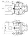
図16は、図7に示したピッカ4に、カートリッジ15に対するフック6の閉じる位置を常に一定に保つためのアクチュエータ16を追加した状態を示すものである。また、図17(a),(b)はアクチュエータ16の形状を明確にする為に、図16からベース13を除去したピッカ4を上側と下側から見たものであり、前述の図8(a),(b)に対応するものである。更に、図18(a)は図17(a)からピッカ4の上側のハウジングを除去した状態を示すものであり、前述の図9の構成にアクチュエータ16を加えた図である。そして、図18(a)の構成にベース13を加えたものが図18(b)である。
【0064】
これらの図から分かるように、アクチュエータ16は、フック6を備えた矩形状のフレーム6aの外側に取り付けられるものであり、底面板16a、側面板16b、背面板16c、及び圧縮ばね18とから構成されている。底面板16aには2本のピン7が挿通されているL字型溝17aがあり、側面板16bには2本のスライドシャフト8が挿通されている長孔17abがある。また、背面板16cは圧縮ばね18によってフック6のある前方に付勢されている。なお、図18(a)に示す矢印aは、フック6の開閉方向を示し、矢印bは、アクチュエータ16の動作方向(前進、後退方向)を示す。
【0065】
図19(a)は、図18(b)からベース13を消し去ったものであり、本発明における重要部品であるフック6、アクチュエータ16、及びガイド14の位置関係を分かり易く示すものである。また、図19(b)は図19(a)の状態をベース13の底面側から見たものである。これらの状態はフック6の動作前の状態であり、アクチュエータ16は、ばね18の付勢によりピッカ4の前方へ突き出ている状態(凸状態)である。また、フック6は、ばね10により閉じる方向へ付勢されているが、ピン7がアクチュエータ16に設けられたL字型溝17aにおける図示する位置(L字の短い方の溝の中)にあるため、フック6は開いている状態である。
【0066】
前述の実施例と同様に、モータ1がピッカ4を前進させる方向に回転を開始すると、モータ1の駆動力は減速機構2、及び駆動ベルト3を介して連結部5に伝わり、ピッカ4がスライドシャフト11に沿って動き出す。この状態は、図19(b)において、アクチュエータ16、ピン7、スライドシャフト8、及びばね10等が図の左側に移動する状態である。
【0067】
モータ1の回転によりピッカ4が前進方向に動き始めると、図20(a)に示す位置関係になる。この位置は前の実施例の図11(a)に相当する。アクチュエータ16のない前述の実施例では、フック6の初期状態は「閉じている状態」であったので、この位置ではピン7がガイド14のテーパ部14bに接触しており、ここからピッカ4が更に進むと、ピン7はテーパ部14bに沿って移動し、閉じていたフック6は開いていく動きであった。一方、この実施例の場合は、アクチュエータ16のL字型溝17aの作用により、フック6の初期状態は「開いている状態」であるので、ここではピン7とガイド14のテーパ部14bの接触はない。
【0068】
なお、図20(a)には、カートリッジ15及びカートリッジ15を収納する収納棚19が示されている。そして、この実施例では、カートリッジ収納棚19の前面部に、アクチュエータ16を作動させる際に必要となるアクチュエータ当接面20が設けられている。
【0069】
モータ1が回転してピッカ4が更に進むと、図20(b)に示す位置関係になる。この位置は前述の実施例における図11(b)に相当する。この位置では、フック6はアクチュエータ16によって開いている状態であるが、ガイド14のストレート部14cには接触している。
【0070】
モータ1の回転によりピッカ4が更に進むと、図21(a)に示す位置関係になる。この位置は前述の実施例における図12(a)に相当する。ここでは、前述の実施例と同様に、フック6はまだ開いている状態で移動を続ける。ピッカ4が更に進むと、図21(b)に示す位置関係になる。この位置は前述の実施例における図12(b)に相当する。アクチュエータ16がない状態では、ピン7が完全にガイド14から外れ、フック6はばね10の付勢力により閉じる。このばね10の付勢力でフック6はカートリッジ15を把持する。しかし、この実施例では、フック6はばね10により閉じる方向へ付勢されているが、ピン7がアクチュエータ16のL字型溝17aにおける図示する位置にあるため、フック6はまだ開いている状態を維持する。
【0071】
モータ1が回転してピッカ4が更に進むと、図22(a)に示す位置関係になる。この位置は、アクチュエータ16の先端が、カートリッジ収納棚19のアクチュエータ当接面20に当接している位置である。実際には、アクチュエータ16はこの図22(a)の直前の位置にてアクチュエータ当接面20に既に当接していた。アクチュエータ16がアクチュエータ当接面20に当接した時点で、アクチュエータ16は更に前進することが不可能な状態になる。このため、アクチュエータ16がアクチュエータ当接面20に当接した後は、アクチュエータ16を除いた、他のピッカ4に含まれる部位全てが図22(b)に示す位置よりも前進する。
【0072】
アクチュエータ16を除いた、他のピッカ4に含まれる部位全てが図22(b)に示す位置よりも前進すると、ばね18が圧縮され始め、このばね18が圧縮された分だけ、アクチュエータ16を除いた他のピッカ4に含まれる部位全てが前進する。そして、アクチュエータ16を除いた、ピッカ4に含まれる他の部位全ての前進により、ピン7の位置がL字溝17aにおける、ピン7の進行方向と直角方向の溝部分(L字の長い方の溝部分)に位置すると、フック6はばね10の付勢力により瞬時に閉じる状態(図22(a)の状態)に至る。
【0073】
実際には、フック6がばね10の付勢力によって閉じると、図22(a)の状態より更にフック6が前進した位置、すなわち、フック6の先端がカートリッジ15の側面に当接する位置でフック6を閉じる。この状態で、ピッカ4の後退動作に移る。この後退動作中に図22(a)の状態となり、フック6と凹部41が嵌合する。これにより、フック6とカートリッジ15の前進、後退方向の各部の寸法交差のばらつきを吸収することができる。
【0074】
この結果、フック6によってカートリッジ15が把持される。図22(b)は、この時の状態を図13の視線にて示したものである。
【0075】
このように、前述の実施例にアクチュエータ16を加えた構成のこの実施例では、アクチュエータ16がカートリッジ収納棚19のアクチュエータ当接面20に突当たる位置を、寸法公差の累積バラツキを加味した上で、必ずピン7がガイド14から外れる位置にさえしておけば、寸法公差の累積バラツキによってロボットハンド30と記録再生装置50と間の距離や、ロボットハンド30とカートリッジ収納棚19との間の距離が装置によって異なった場合でも、常に決まった位置でフック6に閉じる動作をさせることができ、フック6が確実にカートリッジ15を把持することが可能になる。
【0076】
なお、フック6がカートリッジ15を把持し終えた後の、カートリッジ15の引込み動作(「復路」)におけるガイド14およびフック6の動作については、アクチュエータ16は関係しておらず、前述の実施例における「復路」の動作と同じであり、フック6とアクチュエータ16の状態は図22(a)に示した状態のまま保持されるので、ここでは「復路」の動作の説明を省略する。
【0077】
次に、ピッカ4がカートリッジ15をベース13の上に引き込んだ後に、カートリッジ15を目的のカートリッジ収納棚19に置きに行く際の動作について説明する。
【0078】
図23(a)はカートリッジ15をベース13の上に引き込んだ直後の状態を示すものであり、図23(b)はこのときのガイド14、カートリッジ15、及びピッカ4の位置をベース13の下側から見たものである。この時、フック6はカートリッジ15を把持した状態であり閉じている。また、アクチュエータ16は、図22(a)の状態のままである。
【0079】
モータ1の回転により、ピッカ4がカートリッジ収納棚19の方向に動き始めると、図24(a)に示す位置関係になる。この位置は前述の実施例における図11(a)に相当する。前述の実施例と同様に、フック6の初期状態は「閉じている状態」であるので、この位置ではピン7がガイド14のテーパ部14bに接触し、ここからピッカ4が更に進むとピン7はテーパ部14bに沿って移動し、閉じていたフック6は開いていく。
【0080】
モータ1が回転してピッカ4が更に進むと、図24(b)に示す位置関係になる。この位置は前述の実施例における図11(b)に相当する。ピン7がガイド14のテーパ部14bを過ぎ、ストレート部14cに到達する。フック6の開き動作はここで終了する。一方、この時、ピン7の位置はL字型溝17aのピン7の進行方向と同じ方向の溝の位置となる。すると、圧縮ばね18に付勢されているアクチュエータ16がピッカ4の進行方向前方に瞬時に移動し、フック6はL字型溝17aによって開いた状態で保持されるようになる。このとき、フック6は把持していたカートリッジ15を完全に放す状態となる。
【0081】
この状態では、カートリッジ15に対する保持手段が無いように見えるが、この時、カートリッジ15の先端から数cmの部分は既にカートリッジ収納棚19の中に入っているため、カートリッジ収納棚19の横壁および上下壁がカートリッジ15のガイド(保持手段)となり、カートリッジ15は姿勢を崩すことは無い。
【0082】
この後、カートリッジ15はピッカ4に押されてカートリッジ収納棚に挿入されて行き、図25(a)、図25(b)に示す位置関係になる。図25(b)で示す位置はこの実施例の図21(b)に相当する。フック6は、ばね10により閉じる方向へ付勢されているが、ピン7がL字型溝17aにおける図示する位置にあるため、フック6はまだ開いている状態を維持する。
【0083】
カートリッジ15をカートリッジ収納棚19に戻す時は、そのままカートリッジ収納棚19にカートリッジ15を戻そうとしても、アクチュエータ16がカートリッジ収納棚19のアクチュエータ当接面20に突き当たり、この結果、フック6は閉じて再びカートリッジ15を掴んでしまう。
【0084】
このため、カートリッジ15をカートリッジ収納棚19に戻す際には、図25(b)の位置までピッカ4を前進させた時に、カートリッジ15の殆どの部分がカートリッジ収納棚19の中に入っているようにし、ロボットハンドごとカートリッジ15の厚み方向(例えば上下のどちらか)に移動させる。一方、カートリッジ収納棚19には、アクチュエータ当接面20のカートリッジ15の厚み方向(例えば上下のどちらか)に、この面20よりも凹んでいる凹部を設けておく。但し、この凹部は面20のなるべく近傍に設け、ピッカ4にてカートリッジ15を押すことが出来る範囲内、即ち、カートリッジ15の厚み寸法の範囲内としておく。この凹部の深さは、この実施例の図22(a)に相当する位置までピッカ4を前進させても、アクチュエータ16が突当たらないような深さにしておく。ロボットハンドごとカートリッジ15の厚み方向(例えば上下のどちらか)に移動させた後、図22(a)に相当する位置までピッカ4を前進させて、カートリッジ15をカートリッジ収納棚19に押し込む。
【0085】
図26は、ロボットハンドをカートリッジ15の下側に移動させた後、図22(a)に相当する位置までピッカ4を前進させて、カートリッジ15をカートリッジ収納棚19に押し込んだ状態を示すものである。
【0086】
このようなロボット制御を行えば、カートリッジ収納棚19にカートリッジ15を挿入する場合に、アクチュエータ16がカートリッジ収納棚19のアクチュエータ当接面20に突当たることがなく、フック6が閉じて再びカートリッジ15を把持するということが無い。
【0087】
カートリッジ15のカートリッジ収納棚への格納が完了した後は、そのままピッカ4を後退させれば、フック6は開いたままで、図21(b)、図21(a)、図20(b)、図20(a)、図19(b)に示した位置を順にたどって図16に示した初期状態となる。以上の動作で、カートリッジ15をカートリッジ収納棚19に収納する動作は完了となる。
【0088】
ところが、このアクチュエータ16を付加した構成では以下のような場合に問題が生じることがあり、全ての記録再生装置に対するカートリッジの押し込み時に対応できるものではなかった。例えば、ライブラリ装置に搭載する記録再生装置は自社製品だけではなく、他社製品も搭載が可能な様に開発するのが一般的であり、他社製記録再生装置に対して「カートリッジ挿入口の特定箇所にアクチュエータ16の逃げとなる凹部」を設けることは、コストアップになるので困難であった。また、磁気テープカートリッジには、前述のように大きく分けて3種類の磁気テープカートリッジが存在しており、使用するカートリッジの種類によって記録再生装置や収納棚へのカートリッジの挿入量が異なるので、全ての種類のカートリッジに対して適切な凹部を、記録再生装置や収納棚に設けることは困難であった。
【0089】
本発明のロボットハンドの3つ目の実施例は、このような問題を解決するために、様々なカートリッジ押し込み量に対応するマウンタを設けたものであり、以下にこの3つ目の実施例についてその構成と動作を説明する。
【0090】
(3)〔マウンタ機構を含めたロボットハンドの総合動作〕
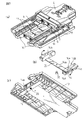
図27(a)は図17a(a)に示したピッカ4をマウンタ21とピッカの本体部分23に分解して示すものであり、図27(b)はマウンタ21を底面側から見たものである。ピッカの本体23は、前述のフック6、ピン7、スライドシャフト8、ストッパ9、ばね10、スライドシャフト11が挿通される連結部12、アクチュエータ16、及びばね18が取り付けられている部位である。ピッカ本体23のこれらの部材の上側には中底23aが設けられており、この中底23aの上に、更に別の2本のスライドシャフト24が、スライドシャフト8と直交する方向に設けられている。また、マウンタ21の上面側には、板ばね22が螺子26によって取り付けられており、板ばね22の両端部にはピン7のガイド部材22Aが設けられている。
【0091】
このガイド部材22Aは、フック6やピン7の動作とマウンタ21との関連動作にとって重要な役割を果たす。このガイド部材22Aは、板ばね22の弾性力により、矢印gの方向に揺動が可能である。また、マウンタ21の裏面側には、ピッカ本体23の中底23aの上に設けられた2本のスライドシャフト24を挿通するための連結部25(前側連結部25Fと後ろ側連結部25R)が設けられている。そして、マウンタ21はこの連結部25をスライドシャフト24に挿通させた状態で、ピッカ本体23の上に取り付けられる。マウンタ21がピッカ本体23に重なっている状態では、後ろ側の連結部25Rがピッカ本体23の後ろ側の内壁29に当接している。マウンタ21はこの状態から、前側の連結部25Fがピッカ本体23の前側の内壁28に当接するまで、スライドシャフト24に沿って矢印fの方向に前進することができる。
【0092】
図28(a)は図19(a)、(b)と同じ位置におけるマウンタ21とフック6のピン7との関係を底面側から見たものである。この図には、フック6及びアクチュエータ16の図示は省略してあり、マウンタ21とガイド部材22Aに対するピン7の位置、及びガイド14の位置のみを示してある。この状態はフック6の動作前の状態であり、フック6はアクチュエータ16のL字型溝17aにより開いている状態である。
【0093】
この実施例では、モータ1による駆動力は、減速機構2、駆動ベルト3、連結部5、マウンタ21、板ばね22、及びガイド部材22Aの順で伝えられる。そして、板ばね22に設けられたガイド部材22Aとピン7との位置関係から分かるように、ガイド部材22Aがピン7を押すことで、ピッカ本体23およびフック6やアクチュエータ16が移動する構成となっている。
【0094】
図28(a)の位置からモータ1の回転によりピッカ4が前進し始めると、図28(b)に示す位置関係になる。この位置はアクチュエータ16を用いた実施例の図22(a)に相当する。この実施例においても、フック6の初期状態は図20(a)同様に「開いている状態」であるので、ピン7はガイド14のテーパ部14bに接触しない。符号19はカートリッジ収納棚である。
【0095】
モータ1が回転してピッカ4が更に進むと、図29(a)に示す位置関係になる。この位置はアクチュエータ16を用いた実施例の図20(b)に相当する。ここでは、フック6はアクチュエータ16によって開いている状態であり、更に、ピン7はガイド14のストレート部14cには接触している。モータ1の回転でピッカ4が更に進むと、図29(b)に示す位置関係になる。この位置はアクチュエータ16を用いた実施例の図21(a)に相当する。ここでは、フック6はまだ開いているおり、ピン7はガイド14のストレート部に接触したままの状態で、ピッカ4は更に移動を続ける。
【0096】
モータ1が回転してピッカ4が更に進むと、図30(a)に示す位置関係になる。この位置はアクチュエータ16を用いた実施例の図21(b)に相当する。アクチュエータ16のない最初の実施例では、この状態の時にはピン7が完全にガイド14から外れてフック6がばね10の付勢力により閉じていた。しかし、この実施例でもアクチュエータ16が使用されているので、フック6はまだ開いている状態を維持する。
【0097】
ピッカ4が更に進むと、図30(b)に示す位置関係になる。この位置はアクチュエータ16を用いた実施例の図22(a)に相当する。つまり、アクチュエータ16の前進がカートリッジ収納棚19のアクチュエータ当接面20によって止められ、ピン7がL字型溝17a内を移動してフック6が閉じた状態である。この時、ピン7は今まで押されていた(接触していた)ガイド部材22Aのピン当接面22hから外れる。しかしながら、前側のピン7は、今度はマウンタ21側のピン当接面21iと接触し、後ろ側のピン7はマウンタ21に設けられた凹部21jに入る。この図30(b)に示す状態は、フック6が閉じ、カートリッジ15を把持した状態である。この時の状態は図22(b)にも示されている。
【0098】
以上が、アクチュエータ16に加えてマウンタ21を用いた時に、フック6がカートリッジ15を把持するまでのメカニズムである。尚、カートリッジ15を把持し終えた後の、カートリッジ15の引込み動作(復路)におけるガイド14、フック6、及びピン7の動作については、最初の実施例の「復路」の動作と同じであり、マウンタ21、板ばね22のガイド部材22Aとピン7の動作については、図30(b)の状態のままであるので、ここではその説明を省略する。
【0099】
次に、カートリッジ15をベース13に引込んだ動作の後で、カートリッジ15を目的のカートリッジ収納棚19に挿入する際の動作について説明する。
【0100】
カートリッジ15をベース13の上に引き込んだ直後の状態は、図23(a)に示されている。この時、フック6は閉じていて、カートリッジ15を把持した状態である。これより、カートリッジ15がベース13より飛び出すことがない。また、アクチュエータ16は、図30(b)の状態のまま、即ち、図23(b)と同じ状態である。よって、前側のピン7はマウンタ21のピン当接面21iに接触しており、後側のピン7は凹部21jの中にある。
【0101】
この図23(b)と同じ状態を、フック6の一部と共に、ピン7、ガイド14、カートリッジ15、マウンタ21、及び板ばね22のガイド部材22Aのみで表示したものが図31(a)である。この状態で、図2(a),(b)に示すように、ロボットハンドの位置を装置の上下方向(矢印A)、装置の幅方向(矢印B)、及び回転方向(矢印C)に移動すれば、任意の場所にカートリッジを移動することができる。
【0102】
以後、図31〜図34を使用して、ピッカ4がカートリッジ15を目的のカートリッジ収納棚19に挿入する場合の、ピン7およびマウンタ21の動作について説明する。
【0103】
図31(a)の状態からモータ1がピッカ4を前進させる方向に回転を始めてピッカ4が動き始めると、ピン7がマウンタ21のピン当接面21i(又は凹部21j)に押されて図31(b)に示す位置関係になる。この位置はアクチュエータ16を用いた実施例の図24(a)に相当し、カートリッジ15がカートリッジ収納棚19に近づいた状態である。前述のように、フック6の初期状態は「閉じている状態」であったので、この位置ではピン7がガイド14のテーパ部14bに接触し、ここからピッカ4が更に進むとピン7はテーパ部14bに沿って移動し、閉じていたフック6は開いていく。
【0104】
モータ1の回転によって更にピッカ4が進むと、図32(a)に示す位置関係になる。この状態は、フック6が開いていく途中過程であり、すでにカートリッジ15の先端部分の一部がカートリッジ収納棚19に押し込まれている。この後のモータ1の回転により、カートリッジ15の一部は更にカートリッジ収納棚19に押し込まれる。モータ1が回転を続けるとピッカ4が更に前進し、これにより、前側のピン7はフック6が開き切る途中でマウンタ21のピン当接面21iから外れ、後側のピン7は凹部21jから出た状態であり、前側のピン7がマウンタ21とガイド部材22Aの間に形成されている溝27のある位置に到達した状態である。この位置では、ピン7はマウンタ21に押されなくなるので、モータ1の駆動力が直接伝わるマウンタ21のみが前進することになる。
【0105】
即ち、ピッカ本体23(図32(a)においてマウンタ21の連結部25に係合する位置にあるが、図示はされていない)はここまでピン7がマウンタ21のピン当接面21i(又は凹部21j)に押されることで移動していたが、図32(a)の状態になった瞬間、ピン7がマウンタ21の溝27に嵌まり込み、マウンタ21から押されなくなってしまったため、ピッカ本体23の移動はここで一旦停止する。
【0106】
この後もマウンタ21にモータ1からの駆動力が継続して伝わるので、図32(b)に示すようにマウンタ21のみが前進する(図32(a)とピン7の位置が変わらないことから、ピッカ本体23が移動していないことが分かる)。この時、前側のピン7は溝27の中に位置すると共に、2つのピン7はマウンタ21の側面21sの上にある。なお、図32(a)の位置において、フック6は把持していたカートリッジ15を完全に放す状態となる。そして、同時に、マウンタ21はフック6の係合から開放されたカートリッジ15を押して進んでいくことになる。この後、マウンタ21が前進しても、2つのピンはマウンタ21の側面21sの上にあるので、フック6が閉じることはない。
【0107】
モータ1の回転によってマウンタ21が更に進むと、図33(a)に示す位置関係になる。この位置はマウンタ21が図示しないスライドシャフト11の長さいっぱいまで移動した位置であり、マウンタ21の連結部25Fの前面が、ピッカ本体23の内壁28に当接した状態である。この位置では、マウンタ21が二点鎖線で示すピッカ本体23の位置よりも前方に突出している。すると、今度はピッカ本体23がマウンタ21の連結部25により内壁28を押されることとなり、ピッカ本体23はマウンタ21と共に移動を再び開始する。
【0108】
マウンタ21がピッカ本体23から前方に突出した状態のピッカ4が、モータ1の回転によって更に進むと、図33(b)に示す位置関係になる。移動を開始したピン7は、この位置にてガイド14のテーパ部14bを過ぎ、ストレート部14cに到達する。つまり、前述のようにフック6(図示せず)がここで開ききることになる。尚、この時、ピン7(フック6)とアクチュエータ16の位置関係のみを言えば、図24(b)と同じである。しかしながら、この状態では、マウンタ21の先端部の方が、破線で示すアクチュエータ16の先端部よりもカートリッジ収納棚19に近い位置にあり、アクチュエータ16の先端部とカートリッジ15の後端部とは、所定の距離だけ離れている。
【0109】
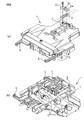
この後、カートリッジ15はマウンタ21に押されてカートリッジ収納棚19に挿入されて行き、図34(a)に示す位置関係になる。尚、この図には、アクチュエータ16やフック6などピッカ本体23が表示されている。この位置は、カートリッジ15のカートリッジ収納棚19への押し込みが完了した位置である。前述のように、マウンタ21がピッカ本体23よりも先行している状態であるので、アクチュエータ16の先端部がカートリッジ収納棚19のアクチュエータ当接面20に接触していない。図34(b)は、この時の状態を図22(b)と同じ視線にて示したものである。
【0110】
このように、マウンタ21を使用した実施例が、「様々なカートリッジ挿入量に対応」している理由は、この図34(a)、(b)から分かるように、カートリッジ収納棚19のアクチュエータ当接面20からアクチュエータ16の先端までの距離の間で、マウンタ21(含ピッカ本体23)の移動量が調整可能であるからである。
【0111】
なお、この実施例では、カートリッジ15を挿入する時の対象はカートリッジ収納棚19であるが、カートリッジ15の挿入対象が記録再生装置であっても同じことであり、アクチュエータ当接面20を記録再生装置の表面とすれば、全く同じメカニズムにて説明ができる。更に、媒体アクセスポート101に装填されるマガジン40においても同様である。そして、アクチュエータ当接面20(記録再生装置表面)にアクチュエータ16が接触しない限り、カートリッジ15の記録再生装置への挿入量(差し込み長さ)に相違があっても、確実にカートリッジ15の挿入動を行うことができる。
【0112】
以上が、ピッカ4の前後動作を行う駆動源と、フック6の開閉動作を行う駆動源とマウンタ21の動作を行う駆動源とを1つの駆動源であるモータ1にて動作させる機構を用いた、カートリッジ15をカートリッジ収納棚19へ挿入するまでのメカニズムである。
【0113】
次に、カートリッジ15のカートリッジ収納棚19への挿入を終えた後の、ピッカ4の後退動作(復路)の際のガイド14、フック6(ピン7)、マウンタ21、及び板ばね22の動作について説明する。
【0114】
図35(a)は、図34(b)の状態を右手前方向から見た状態を示すものである。以後、この視線にて「復路」における図34(a)に示したのガイド14、フック6を動作させるピン7、マウンタ21、及び板ばね22の動作を説明する。
【0115】
マウンタ21がカートリッジ15をカートリッジ収納棚19に挿入し終わった図35(a)に示す状態から、モータ1がピッカ4を後退させる方向に回転すると、先ずマウンタ21のみが後退を始める。これは、前述の図32(a)に示した状態から図33(a)に示した状態までは、ピッカ本体23に対してマウンタ21のみがスライドしたため、ピッカ本体23は、マウンタ21により押されるまで動かないからである。
【0116】
一方、この時フック6は完全に開いている状態であるので、丁度、板ばね22におけるピン当接面22hが設けられているガイド部材22Aの後方の、ガイド部材22Aが後退する進路上にピン7が有る状態となっている。よって、この後のマウンタ21の後退動作により、ガイド部材22Aの後方に形成されたテーパ部22jが、図35(b)に示すように、前側のピン7と接触する。
【0117】
一方、前述のように、板ばね22は上下方向に弾性変形可能であるが、ここでは、板ばね22が変形するために必要な力以上の力がテーパ部22jにかからないと板ばね22は変形しない。板ばね22がピン7に乗り上げる形まで変形するには、ピン7を含むピッカ本体23が固定されている時などのように、大きな力が板ばね22のテーパ部22jに加わる必要があるが、この時、ピッカ本体23は、スライドシャフト11に沿って移動可能な状態であり、ピッカ本体23を移動させるのに必要な力は、板ばね22が変形しない程度に少なくて済むよう設計されているので、板ばね22は変形しない。
【0118】
このため、図35(b)の状態では、板ばね22におけるテーパ部22jがピン7を押す状態となり、この結果、マウンタ21に設けられた板ばね22のテーパ部22jを介してピッカ本体23が押され、図35(b)に示す状態からマウンタ21及びピッカ本体23は共に後退していく。
【0119】
なお、この時のフック6(ピン7)とアクチュエータ16、及びガイド14の状態/位置関係は図33(b)と同様であるので、ピン7を含むピッカ本体23の進路には何も障害物はなく、スムーズにマウンタ21及びピッカ本体23は後退できる。マウンタ21が更に後退していくと、図35(c)に示す位置関係になる。この状態は、ピッカ本体23が後退しきった状態(待機状態の位置)であり、マウンタ21とピッカ本体23との位置関係は変わらない。
【0120】
モータ1が更にピッカ4を後退させる方向に回転し、このモータ1の駆動力が更にマウンタ21へ伝わると、図36(a)に示す状態になる。この状態では、ピッカ本体23は、これ以上後退できない状態、つまり固定されているに等しい状態となるので、マウンタ21のみが後退を続け、板ばね22のガイド部材22Aのテーパ部22jには、板ばね22がピン7に乗り上げるに十分な力が加わる。この結果、板ばね22は弾性変形し、ガイド部材22Aのテーパ部22jがピン7押されて変形し、上方に移動して図36(b)の状態となる。マウンタ21はこのままガイド部材22Aを押し上げたまま後退する。
【0121】
板ばね22のガイド部材22Aがピン7に乗り上げた状態でマウンタ21が後退を続けると、ガイド部材22Aをピン7が通過した時点で、板ばね22は自己の持つ弾性力により、図36(c)に示す元の状態に復元する。一方、板ばね22が元の状態に復元すると同時に、マウンタ21の連結部25の後側における後面がピッカ本体23の内壁(後側)29に突当たり、マウンタ21の後退動作も終了となる。この図36(c)に示す状態は、マウンタ21の後端面がピッカ本体23の後端面の位置に一致した状態、即ち、マウンタ21の後退動作が完了した時の状態であり、ピッカ4が全ての動作を開始する前の図16に示す状態と全く同じ状態である。
【0122】
以上説明したように、本発明のピッカ4に採用した機構によれば、ピッカ4の前後動作を行う駆動源、フック6の開閉動作を行う駆動源、及びマウンタ21の動作を行う駆動源とを1つの駆動源(モータ1)にて動作させることができる。また、フック6の開閉動作を直線運動としたので、1/2インチカートリッジ、LTOカートリッジや、DLT16/S−DLTカートリッジのような、幅寸法の異なる3種類の磁気テープカートリッジをフック6で把持することができる。更に、ピッカ4の本体部23の上を移動できるマウンタ21を設けたことにより、カートリッジ15のカートリッジ収納棚19又は記録再生装置50への挿入量が異なる場合であっても、適切な挿入を行うことができる。
【0131】
なお、以上の実施例では、磁気テープを内蔵するカートリッジを搬送するロボットハンドの構造を説明したが、カートリッジに内蔵される記録媒体は特に限定されるものではない。
【0132】
以上、本発明を特にその好ましい実施の形態に基づいて詳細に説明した。本発明の容易な理解のために、本発明の具体的な形態を以下に付記する。
【0133】
(付記1) 移動される物品(15)を収納した棚 (19)から他の場所へこの物品を搬送するロボットハンド(30)であって、ベース(13)と側壁(32)と天井板(31)とからなるハウジングと、前記ハウジングの内部空間を前後方向にスライド可能に構成されたハンド機構(4)と、前記ハンド機構(4)に設けられ、このハンド機構(4)の移動方向と直交する方向に開く動作と閉じる動作を行うことができ、閉じた状態で前記物品(15)を把持する一対のフック(6)と、前記ベース(13)上に設けられ、前記ハンド機構(4)の移動時に前記フック(6)に開閉動作を行わせる左右一対のガイド(14)、及び前記ハンド機構(4)に前後動作及びフック(6)に開閉動作を行わせる唯一の駆動源(1)が設けられ、
前記ハンド機構(4)には、前記第1のシャフト(11)に直交する方向に第2のシャフト(8)が設けられており、前記一対のフック(6)は、この第2のシャフト(8)に沿って移動できる2つの枠体(6a,6b)にそれぞれ突設され、
前記2つの枠体(6a,6b)は、ばね(10)によって互いに近づく方向に付勢された状態で連結されていると共に、所定位置に設けられたストッパ(9)により、通常は前記フック(6)が前記カートリッジ(15)を把持する位置で係止され、
前記2つの枠体(6a,6b)には、それぞれ少なくとも1本のピン(7)が植設されており、前記ハンド機構(4)の前後動作時に、このピン(7)が前記ガイド(14)に係合して前記フック(6)の開閉動作を行わせるように構成され、
前記ガイド(14)には、前記ハンド機構(4)の前進時に、前記ピン(7)に係合して前記フック(6)を開く方向に移動させるテーパ部(14b)、このテーパ部(14b)に連続するストレート部(14c)、及び前記ハンド機構(4)の後退時に、前記ピン(7)をこのガイド(14)の上面(14e)に乗り上げさせる傾斜部(14d)が設けられており、前記ハンド機構(4)の前進時に、前記ピン(7)が前記ガイド(14)の前記ストレート部(14c)を過ぎた時に、前記フック(6)が閉じて前記カートリッジ(15)を把持するように構成され、
前記ハンド機構(4)に、前記ピン(7)と前記第2のシャフト(8)に係合すると共に、ばね(18)によって前記ハンド機構(4)の前進方向に付勢されており、その先端部が前記フック(6)の先端部よりも前方に位置する作動板(16)が設けられており、この作動板(16)は、前記ハンド機構(4)が前進して、前記ピン(7)が前記ガイド(14)の前記ストレート部(14c)を過ぎた後も、前記フック(6)の閉じを防止するように構成されると共に、前記ハンド機構(4)が更に前進して、前記作動板(16)の先端部が前記棚(19)の一部に当接した後に、前記フック(6)を閉じて前記カートリッジ(15)を把持するように構成され、
前記ハンド機構(4)に、前記カートリッジ(15)を前記記録再生装置(50)又は前記棚(19)に投入する際に、前記カートリッジ(15)を押し込む機能を果たすマウンタ(21)が設けられており、このマウンタ(21)は、前記ハンド機構(4)の本体部分(23)のべースに敷設された2本の第1のシャフト(11)と同じ方向に設けられた第3のシャフト(24)上を移動できるように構成されていると共に、前記連結部(5)で前記駆動源(1)の駆動力を伝える駆動ベルト(3)に接続していることを特徴とするロボットハンド。
【0139】
(付記2) 前記マウンタ(21)の前方部近傍の両側に、一対のガイド部材(22A)が、その中央部が前記マウンタ(21)に固定された板ばね(22)の両端に取り付けられて設けられており、
このガイド部材(22A)の前面部(22h)は、前記フック(6)が開いた状態において前記ピン(7)に当接する位置に設けられており、
前記マウンタ(21)には、前記前面部(22h)と同一平面上にあり、前記フック(6)が閉じた状態において前記ピン(7)に当接する当接面(21i)が設けられており、
前記前面部(22h)と前記当接面(21h)の間には、前記ピン(7)を通過させる溝(27)が設けられており、
前記フック(6)によって前記カートリッジ(15)を把持する際には、前記前面部(22h)によって前記ハンド機構(4)の本体部分(23)を移動させ、
前記フック(6)で把持した前記カートリッジ(15)を前記棚(19)又は前記記録再生装置(50)に挿入する際には、前記当接面(21h)によって前記ハンド機構(4)の本体部分(23)を移動させ、前記ピン(7)が前記ガイド(14)のテーパ部(14b)に係合して前記フック(6)が前記カートリッジ(15)の把持を解除した時点で、前記ピン(7)に前記溝(27)を通過させることにより、前記ハンド機構(4)の本体部分(23)の前進を一時停止させ、前記マウンタ(21)を前記本体部分(23)に対して先行させることにより、このマウンタ(21)で前記カートリッジ(15)を前記棚(19)又は前記記録再生装置(50)に挿入するように構成したことを特徴とする付記1に記載のロボットハンド。
【0140】
(付記3) 前記ハンド機構(4)は、前記作動板(16)の作用により、前記ハンド機構(4)が前後のスライド動作を2往復分行うと、必ずフック(6)が開いている状態となるよう構成したことを特徴とする付記1に記載のロボットハンド。
【0142】
【発明の効果】
以上説明したように、本発明のロボットハンドによれば、以下のような効果がある。
【0143】
(1)ピッカの前後動作とフックの開閉動作および、マウンタ動作を一つの駆動源にて行うことができる。
【0144】
(2)装置および他機構部等の部品寸法公差バラツキの累積によって、ロボットハンドと記録再生装置間の距離や、ロボットハンドとカートリッジ収納棚間の距離が、装置によって異なった場合でも、常に最適の位置でフックの閉じる動作を行うことができる。
【0145】
(3)情報記憶装置用の3種類の磁気テープカートリッジに対するハンドリング、及び使用するカートリッジが異なる記録再生装置や様々な製造会社の記録再生装置に対応可能であるように構成されたロボットハンドのピッカ開閉機構を実現することができる。
【0146】
(4)高信頼であり小型化/廉価に適したロボットハンドを達成できる。
【図面の簡単な説明】
【図1】 (a)は本発明が適用される磁気テープライブラリ装置を正面側から見た斜視図、(b)は(a)のライブラリ装置を背面側から見た斜視図である。
【図2】 (a)は図1(a)に示すライブラリ装置の内部構成を示す斜視図、(b)は(a)のライブラリ装置の内部構成を示す平面図である。
【図3】 (a)はLTO媒体を背面側から見た斜視図、(b)はLTO媒体の正面図、(c)はLTO媒体の平面図、(d)はLTO媒体の背面図、(e)はLTO媒体の側面図である。
【図4】 (a)はDLT媒体を背面側から見た斜視図、(b)はDLT媒体の正面図、(c)はDLT媒体の平面図、(d)はDLT媒体の背面図、(e)はDLT媒体の側面図である。
【図5】 (a)は本発明の一実施例のロボットハンドを正面右側から見た斜視図、(b)は(a)のロボットハンドを正面左側から見た斜視図である。
【図6】 (a)は図5(a)に示したロボットハンドをベースと上部ハウジングに分解して示す分解斜視図、(b)は(a)に示した上部ハウジングを底面側から見た斜視図である。
【図7】 (a)は図6(a)に示したベースからサイドプレートとアクチュエータを取り去った状態を示す斜視図、(b)は(a)のガイドの詳細を示す斜視図、(c)は(a)のベースを底面側から見た斜視図である。
【図8】 (a)は図7(a)に示したピッカの駆動ベルトとの接続を説明する斜視図、(b)は(a)に示したピッカを底面側から見た斜視図である。
【図9】 (a)は図8(a)に示したピッカの内部にあるフックとスライドシャフトとの状態を示す斜視図、(b)は(a)に示したフックとスライドシャフトのベース上の位置及びガイドとの位置関係を説明する斜視図である。
【図10】 (a)は図9(b)からベースを除去した状態を示す斜視図、(b)は(a)の状態を底面側から見た平面図(底面図)である。
【図11】 (a)はピッカの移動によりフックを動作させるピンがガイドのテーパ部に係合した状態を示す底面図、(b)は(a)に示したピンがガイドのストレート部に係合した状態を示す底面図である。
【図12】 (a)は図11(a)の状態からフックが更に進んでカートリッジに近づいた状態を示す底面図、(b)は(a)の状態からフックが更に進み、フックとガイドとの係合が外れてフックがカートリッジに係合した状態を示す底面図である。
【図13】 図7(a)に示したピッカがベース上を移動して図12(b)と同じ状態になった時を示す斜視図である。
【図14】 フックがカートリッジを把持した図13の状態からピッカが図7(a)の位置に戻る際のフックとガイドとの関係を説明するものであり、(a)はフックのピンがガイドに係合する直前の状態を示す側面図、(b)はフックのピンがガイドの傾斜部に係合してガイドが撓んだ状態を示す側面図、(c)はフックのピンがガイドの上面に係合してガイドが押し下げられた状態を示す側面図、(d)はフックのピンがガイドのテーパ部の位置になり、ガイドが元の位置に復帰した状態を示す側面図である。
【図15】 図7(a)に示したピッカがフックによって把持したカートリッジをベースの上に引き込んだ状態を示す斜視図である。
【図16】 図7(a)に示したピッカにアクチュエータを追加した状態を示す斜視図である。
【図17】 (a)は図16からベースを除去した状態を示す斜視図、(b)は(a)を底面側から見た斜視図である。
【図18】 (a)は図9(a)に示したフックとスライドシャフトにアクチュエータを加えた構成を示す斜視図、(b)は(a)に示したフック、スライドシャフト及びアクチュエータのベース上の位置及びガイドとの位置関係を説明する斜視図である。
【図19】 (a)は図18(b)からベースを除去した状態を示す斜視図、(b)は(a)の状態を底面側から見た平面図(底面図)である。
【図20】 (a)は図11(a)と同じ状態を示すものであり、フックがアクチュエータによりガイドに接触しない状態を示す底面図、(b)は図11(b)と同じ状態を示すものであり、フックのピンがガイドのストレート部に達した状態を示す底面図である。
【図21】 (a)は図20(b)から更にフックが進んだが、フックのピンがガイドのストレート部に残っている状態を示す底面図、(b)はフックのピンがガイドのストレート部を通過したが、フックがアクチュエータにより開いた状態のままであることを示す底面図である。
【図22】 (a)はアクチュエータの先端部がカートリッジ収納棚に当接することによりフックのピンがアクチュエータのL字溝内を移動し、フックが閉じてカートリッジを把持した状態を示す底面図、(b)は図16に示したピッカがベース上を移動して図22(a)と同じ状態になった時を示す斜視図である。
【図23】 (a)は図16に示したピッカがフックによって把持したカートリッジをベースの上に引き込んだ状態を示す斜視図、(b)は(a)のフック、アクチュエータ、及びカートリッジの状態を底面側から見た底面図である。
【図24】 図23(b)の状態からカートリッジを収納棚に戻す状態を説明するものであり、(a)はピッカの移動によりフックを動作させるピンがガイドのテーパ部に係合した状態を示す底面図、(b)は(a)に示したピンがガイドのストレート部に係合してフックが開くと共に、フックが開状態でアクチュエータのL字溝に保持された状態を示す底面図である。
【図25】 (a)は図24(b)の状態からピッカが更にカートリッジ収納棚に近づいた状態を示す底面図、(b)はアクチュエータの先端部が収納棚に当接する寸前まで近づいた状態を示す図である。
【図26】 図25(b)の状態からピッカが収納棚に対して上下方向に移動し、アクチュエータの先端部が収納棚に当接しない状態でピッカによってカートリッジが収納棚に収納された状態を示す底面図である。
【図27】 (a)は図17(a)に示したピッカをマウンタとピッカの本体部分に分解して示す分解斜視図、(b)は(a)のマウンタを底面側から見た斜視図である。
【図28】 (a)は図19(a)と同じ位置におけるマウンタとフックのピンとの関係を示す底面図、(b)は図20(a)と同じ位置におけるマウンタとフックのピンとの関係を示す底面図である。
【図29】 (a)は図20(b)と同じ位置におけるマウンタとフックのピンとの関係を示す底面図、(b)は図21(a)と同じ位置におけるマウンタとフックのピンとの関係を示す底面図である。
【図30】 (a)は図21(b)と同じ位置におけるマウンタとフックのピンとの関係を示す底面図、(b)は図22と同じ位置におけるマウンタとフックのピンとの関係、及びフックとカートリッジとの係合を示す底面図である。
【図31】 (a)は図23(b)と同じ位置におけるマウンタ、フックのピン、カートリッジ及びガイドとの関係を示す底面図、(b)は図24(a)と同じ位置におけるマウンタ、フックのピン、カートリッジ及びガイドとの関係を示す底面図である。
【図32】 (a)は図31(b)の状態から更にピッカが収納棚に近づき、マウンタに押されていたフックのピンがマウンタの溝に入って押されなくなった状態を示す底面図、(b)は(a)の状態からマウンタのみがカートリッジを押しながら収納棚に近づいた状態を示す底面図である。
【図33】 (a)はピッカ本体に対して移動していたマウンタが、ピッカ本体の前側の内壁に当接して移動が止まった状態を示す底面図、(b)はマウンタと共にフックも移動し、フックのピンがガイドのストレート部に達した状態を示す底面図である。
【図34】 (a)はカートリッジがマウンタに押されて収納棚内に完全に挿入された状態を、アクチュエータとピッカの本体部分と共に示す底面図、(b)は(a)の状態を、図23(a)の状態と同じ視点で見た斜視図である。
【図35】 (a)は図34(a)の状態におけるフックのピン、ガイド、カートリッジ、及びマウンタを抜き出して側面から見た側面図、(b)は(a)の状態からマウンタのみが後退した状態を示す側面図、(c)は(b)の状態からマウンタにフックが押されてピッカが後退した状態を示す側面図である。
【図36】 (a)はピッカが後退できない状態で更にマウンタが後退する状態を示す側面図、(b)はマウンタが板ばねを弾性変形させながら更に後退する状態を示す側面図、(c)はマウンタがピッカ本体の後側の内壁に当接して移動が止まった状態を示す側面図である。
【符号の説明】
1…モータ(駆動源)
3…ベルト
4…ピッカ
5…連結部
6…フック
7…ピン
8…スライドシャフト
11…スライドシャフト
12…連結部
13…ロボットハンドのベース
14…ガイド
15…カートリッジ
16…アクチュエータ
17a…L字溝
19…カートリッジ収納棚
20…アクチュエータ当接面
21…マウンタ
22…板ばね
22A…ガイド部材
23…ピッカの本体
24…スライドシャフト
25…連結部
27…溝
30…ロボットハンド
31…上部ハウジング
40…マガジン
50…記録再生装置
60…棚
70…ロボット
100…磁気テープライブラリ装置[0001]
BACKGROUND OF THE INVENTION
The present inventionRobot hand in automatic cartridge loading deviceIn particular, a cartridge that is connected to a computer or the like via a network and contains a magnetic tape or the like is moved in the apparatus, information is recorded and reproduced on the cartridge, and the cartridge is stored in the apparatus.Robot hand in automatic cartridge loading deviceAbout.
[0002]
[Prior art]
2. Description of the Related Art Conventionally, as an amount of information in a computer system increases, a cartridge-type recording medium (hereinafter simply referred to as a cartridge) containing a magnetic tape (a magneto-optical disk, a digital video disk, etc.) as an information storage device for storing a large amount of information Library device usingEtc.Automatic cartridge loadingEquipmentis there. Such an apparatus includes a recording / reproducing apparatus that records or reproduces data on a cartridge type recording medium, a plurality of shelves that can store the medium, and a robot hand that conveys a cartridge as a recording medium. Built in.
[0003]
The robot hand is movable in all three-dimensional directions in the apparatus in order to automatically insert / extract the cartridge from / to the recording / reproducing apparatus and the shelf and transport the cartridge. Also, the robot hand takes out the cartridge from the recording / reproducing device or shelf when transporting the cartridge, temporarily stores it in the robot, then transports it, and then puts the cartridge into the target recording / reproducing device or shelf. Perform the action. A hand mechanism in which the robot hand handles the cartridge is called a picker. As a method of handling the cartridge by the picker, there is a method of gripping with a hook hooked on a groove or the like in the cartridge, or a method of gripping the cartridge itself.
[0004]
(1)The robot hand of the library apparatus using the magnetic tape cartridge has a mechanism dedicated to the operation and a driving source for the forward / backward movement of the picker and the opening / closing operation of the hook for holding the cartridge.In addition, it is configured so that the front / rear movement of the picker and the opening / closing operation of the hook can be performed by one driving source.Is common. In addition, when a cartridge is inserted into the recording / reproducing apparatus and the cartridge storage shelf, there is a device equipped with a mechanism called a mounter having a role of inserting the cartridge into the recording / reproducing apparatus or the cartridge storage shelf, and this mounter is operated. In addition, those having a drive source dedicated to the operation are generally used.However, there is no structure that can perform the three operations of the mounter, the forward / backward movement of the picker, and the hook opening / closing operation with a single drive source.
[0005]
(2)By the way, the cartridges used in such library devices are 1/2 inch cartridges used in information storage devices in the mainframe market, and LTO cartridges and DLTs used in information storage devices in the open market. There are roughly three types of magnetic tape cartridges, / S-DLT cartridges. When the type of cartridge is different, the size of the cartridge itself is different. Even if the recording / reproducing apparatus uses the same cartridge, the format of the recording / reproducing apparatus(Difference between manufacturers, etc.)Recording and playback device byAgainstCartridgePush amountIs differentYes.
[0006]
On the other hand, the recording / reproducing device mounted on the library device or the like belongs to a specific manufacturer, and the push amount of the cartridge into the recording / reproducing device and the cartridge storage shelf is made constant. It is assumed that the mounter does not operate by itself, and the recording / reproducing device in the picker is constant in the picker movement amount for both the pulling out / pushing of the cartridges into / from the cartridge storage shelf (for different movement amounts). There is a robot hand mechanism.
[0008]
[Problems to be solved by the invention]
However,Regarding (1) described in the prior art, there are the following concerns. That is,Before and after pickerOperation and hook opening / closing operation can be performed by a single drive source (motor / solenoid, etc.).Since the number of drive sources is large, the control circuit becomes complicated and the cost increases. As the number of drive sources increases, the mounting space for other drive units is compressed in order to secure the mounting space for the drive sources, resulting in a complicated robot structure / increase in the number of parts and cost. There was a problem that.
[0009]
Also, the front / rear movement of the picker and the opening / closing movement of the hook are performed by one drive source.In the mechanismThe timing of closing the hook was always constant. For this reason, when the distance between the robot hand and the recording / reproducing apparatus or the cartridge storage shelf varies depending on the apparatus due to the accumulation of the component size tolerance variations of the apparatus and other mechanism units, the optimum hook should be closed with respect to the cartridge. The phenomenon that it cannot be closed at the position occurs. If the distance between the set robot hand and the recording / reproducing apparatus or the cartridge storage shelf is long, the hook closes in front of the optimum position, and the hook cannot grasp the cartridge. Conversely, if the distance between the robot hand and the recording / reproducing device or the cartridge storage shelf is short, the hook has reached the position where it must be closed, but the hook does not close and the hook cannot grasp the cartridge. A failure will occur.
[0011]
However,Regarding (2) described in the prior art, there are the following concerns. That is,Library deviceEtc.In the automatic cartridge loading device, specifying the type of cartridge to be used and the type of recording / reproducing device can meet the needs of users in devices for the open market, which has been rapidly expanding in recent years. There is no fear that it can lead to missing business opportunities. For example, a single library apparatus or automatic cartridge loading apparatus may use only one type of cartridge, but a recording / reproducing apparatus to be mounted may have a plurality of formats or a desire to install a recording / reproducing apparatus of a manufacturer. It is never possible to meet the desire to mount a recording / reproducing device for LTO and a recording / reproducing device for S-DLT in a library device or an automatic cartridge loading device. In addition, in the open market, in recent circumstances where it is completely unknown which cartridge, LTO or DLT / S-DLT, will expand in scale and which will decline, the type of cartridge used and the recording / reproducing apparatus I want to avoid specifying the form of.
[0013]
Therefore, an object of the present invention is to solve the problem of the robot hand in the conventional library apparatus, and is inexpensive and highly reliable.Robot hand in automatic cartridge loading deviceIs to provide.
[0014]
[Means for Solving the Problems]
The present invention achieves the above object.According to the present invention, the front / rear operation of the hand mechanism, the opening / closing operation of the hook, and the mounter operation can be performed by one drive source, and the distance between the hand mechanism and the recording / reproducing apparatus, the hand mechanism and the cartridge storage shelf Even if the distance between the two varies depending on the device due to the accumulation of variations in the size of parts such as the device and other mechanisms, the hook can always be closed at the optimum position, and the cartridge can be securely hooked. In addition, the handling and use of the three types of magnetic tape cartridges for the information storage device can be used for different recording / reproducing devices and recording / reproducing devices of various manufacturers. A robot hand in an automatic cartridge loading device is provided.
[0020]
In addition, it is highly reliable, has a small mounting space / simple structure, and is suitable for downsizing / inexpensive.Robot hand in automatic cartridge loading deviceIs achieved.
[0022]
DETAILED DESCRIPTION OF THE INVENTION
Embodiments of the present invention will be described below in detail based on specific examples with reference to the accompanying drawings.
[0023]
FIG. 1A shows the magnetic
[0024]
FIG. 2A shows the internal configuration of the
[0025]
Such a
[0026]
The
[0027]
3A and 3B show an
[0028]
In the
[0029]
4A and 4B show a DLT medium 15B which is another type of
[0030]
For the DLT medium 15B,Its
[0031]
In a library apparatus using a magnetic tape cartridge, a
[0032]
Here, an operation in which the robot hand in the
[0033]
(1) [Mechanism for performing front / rear movement of picker and opening / closing operation of hook with one drive source]
FIG. 5A shows the
[0034]
FIG. 6A shows the
[0035]
The
[0036]
In the following description, among the operations in which the
[0037]
FIG. 7A shows a state in which the
[0038]
Inside the
[0039]
The
[0040]
FIG. 8A shows only the
[0041]
On the bottom surface side of the
[0042]
FIG. 9A shows the relationship between the
[0043]
Further, the two
[0044]
Here, a detailed description will be given of a configuration in which the front / rear operation of the
[0045]
FIG. 10A shows the relationship between the
[0046]
As described with reference to FIGS. 5 to 9, when the
[0047]
FIG. 11A shows a state in which the
[0048]
In this embodiment, the opening / closing timing of the
[0049]
When the
[0050]
When the
[0051]
In this case, in order to close the
[0052]
FIG. 13 shows the state at this time viewed from the same viewpoint as FIG. 7A, and shows a state where the
[0053]
The above operation is the mechanism of the opening / closing operation of the
[0054]
FIG. 14A shows the positions of the
[0055]
This is because, as described with reference to FIG. 7, the
[0056]
When the
[0057]
When the
[0058]
The
[0059]
As described above, in the present invention, since the
[0060]
By the way, in the configuration described above, the position at which the
[0061]
However, when accurate position control cannot be performed on the
[0062]
In order to solve this problem, in the present invention, a mechanism is added in which the
[0063]
(2) [Mechanism to always stop and close the hook at the optimum position and close it at the optimum position]
FIG. 16 shows a state where an
[0064]
As can be seen from these drawings, the
[0065]
FIG. 19A shows the base 13 removed from FIG. 18B, and shows the positional relationship among the
[0066]
As in the previous embodiment, when the
[0067]
When the
[0068]
FIG. 20A shows the
[0069]
When the
[0070]
When the
[0071]
When the
[0072]
When all the parts included in the
[0073]
Actually, when the
[0074]
As a result, the
[0075]
As described above, in this embodiment having the configuration in which the
[0076]
Note that the
[0077]
Next, an operation when the
[0078]
FIG. 23A shows a state immediately after the
[0079]
When the
[0080]
When the
[0081]
In this state, it seems that there is no holding means for the
[0082]
Thereafter, the
[0083]
When returning the
[0084]
For this reason, when returning the
[0085]
FIG. 26 shows a state in which after the robot hand is moved to the lower side of the
[0086]
If such robot control is performed, when the
[0087]
After the storage of the
[0088]
However, in the configuration in which the
[0089]
In the third embodiment of the robot hand of the present invention, in order to solve such a problem, mounters corresponding to various cartridge push-in amounts are provided. The third embodiment will be described below. The configuration and operation will be described.
[0090]
(3) [Total operation of robot hand including mounter mechanism]
FIG. 27A shows the
[0091]
The
[0092]
FIG. 28 (a) shows the relationship between the
[0093]
In this embodiment, the driving force by the
[0094]
When the
[0095]
When the
[0096]
When the
[0097]
When the
[0098]
The above is the mechanism until the
[0099]
Next, the operation when the
[0100]
The state immediately after the
[0101]
FIG. 31 (a) shows the same state as FIG. 23 (b) with only a part of the
[0102]
Hereinafter, the operations of the
[0103]
When the
[0104]
When the
[0105]
That is, in the picker main body 23 (in a position where it is engaged with the connecting
[0106]
Since the driving force from the
[0107]
When the
[0108]
When the
[0109]
Thereafter, the
[0110]
As described above, the reason why the embodiment using the
[0111]
In this embodiment, the
[0112]
As described above, the mechanism that operates the drive source that performs the back-and-forth operation of the
[0113]
Next, the operation of the
[0114]
FIG. 35 (a) shows the state of FIG. 34 (b) viewed from the right front side. Hereinafter, the operations of the
[0115]
When the
[0116]
On the other hand, since the
[0117]
On the other hand, as described above, the
[0118]
For this reason, in the state of FIG. 35B, the tapered portion 22j of the
[0119]
Since the state / positional relationship between the hook 6 (pin 7), the
[0120]
When the
[0121]
When the
[0122]
As described above, according to the mechanism employed in the
[0131]
In addition,In the above embodiment, the structure of the robot hand that conveys the cartridge containing the magnetic tape has been described. However, the recording medium incorporated in the cartridge is not particularly limited.
[0132]
The present invention has been described in detail based on the preferred embodiments. For easy understanding of the present invention, specific embodiments of the present invention will be described below.
[0133]
(Supplementary note 1) A robot hand (30) for transporting an article (15) from a shelf (19) containing an article (15) to be moved to another place, including a base (13), a side wall (32), a ceiling board ( 31), a hand mechanism (4) configured to be slidable in the front-rear direction in the internal space of the housing, and provided in the hand mechanism (4), the movement direction of the hand mechanism (4) A pair of hooks (6) for gripping the article (15) in a closed state, which can be opened and closed in an orthogonal direction, and provided on the base (13), the hand mechanism (4 ), A pair of left and right guides (14) that cause the hook (6) to open and close, and a single drive source (1) that causes the hand mechanism (4) to open and close and open and close the hook (6). )And
The hand mechanism (4) is provided with a second shaft (8) in a direction orthogonal to the first shaft (11), and the pair of hooks (6) is connected to the second shaft ( 8) Projected on two frames (6a, 6b) that can move alongAnd
The two frames (6a, 6b) are connected in a state where they are biased toward each other by a spring (10), and are usually connected to the hooks (9) by a stopper (9) provided at a predetermined position. 6) is locked at the position where the cartridge (15) is gripped.And
At least one pin (7) is implanted in each of the two frames (6a, 6b), and when the hand mechanism (4) is moved back and forth, the pin (7) is connected to the guide (14). ) To open and close the hook (6).Configured as
The guide (14) includes a tapered portion (14b) that engages with the pin (7) and moves the hook (6) in the opening direction when the hand mechanism (4) moves forward, and this tapered portion (14b ) And a straight part (14c) that continues to the upper part (14e) of the guide (14) when the hand mechanism (4) is retracted. When the hand mechanism (4) moves forward, when the pin (7) passes the straight portion (14c) of the guide (14), the hook (6) is closed to grip the cartridge (15).Configured as
The hand mechanism (4) is engaged with the pin (7) and the second shaft (8) and is urged by the spring (18) in the forward direction of the hand mechanism (4), An operating plate (16) whose front end is positioned in front of the front end of the hook (6) is provided, and this operating plate (16) is moved forward by the hand mechanism (4), and the pin ( 7) is configured to prevent the hook (6) from closing even after the straight portion (14c) of the guide (14) has passed, and the hand mechanism (4) further advances, After the tip of the operation plate (16) abuts a part of the shelf (19), the hook (6) is closed to hold the cartridge (15)And
The hand mechanism (4) is provided with a mounter (21) that functions to push in the cartridge (15) when the cartridge (15) is inserted into the recording / reproducing device (50) or the shelf (19). The mounter (21) has a third direction provided in the same direction as the two first shafts (11) laid on the base of the body portion (23) of the hand mechanism (4). It is configured to be able to move on the shaft (24), and is connected to a driving belt (3) that transmits the driving force of the driving source (1) at the connecting portion (5).RoboHand.
[0139]
(Appendix2A pair of guide members (22A) are provided on both sides in the vicinity of the front portion of the mounter (21), with the central portion attached to both ends of the leaf spring (22) fixed to the mounter (21). And
The front surface portion (22h) of the guide member (22A) is provided at a position where it abuts on the pin (7) when the hook (6) is open.
The mounter (21) is provided with a contact surface (21i) that is flush with the front surface portion (22h) and contacts the pin (7) when the hook (6) is closed. ,
Between the front surface portion (22h) and the contact surface (21h), a groove (27) for allowing the pin (7) to pass therethrough is provided,
When gripping the cartridge (15) by the hook (6), the main body portion (23) of the hand mechanism (4) is moved by the front surface portion (22h),
When the cartridge (15) gripped by the hook (6) is inserted into the shelf (19) or the recording / reproducing device (50), the main body of the hand mechanism (4) is formed by the contact surface (21h). When the portion (23) is moved, the pin (7) is engaged with the tapered portion (14b) of the guide (14) and the hook (6) releases the grip of the cartridge (15). By passing the groove (27) through the pin (7), the advancement of the body part (23) of the hand mechanism (4) is temporarily stopped, and the mounter (21) is moved relative to the body part (23). Note that the mounter (21) is configured to insert the cartridge (15) into the shelf (19) or the recording / reproducing device (50) by preceding the mounting device.1The robot hand described in 1.
[0140]
(Appendix3) When the hand mechanism (4) performs the back-and-forth slide operation for two reciprocations by the action of the operation plate (16), the hand mechanism (4) is always in a state where the hook (6) is opened. Addendum characterized by comprising1The robot hand described in 1.
[0142]
【The invention's effect】
As described above, the robot hand according to the present invention has the following effects.
[0143]
(1) The front-rear operation of the picker, the hook opening / closing operation, and the mounter operation can be performed by one drive source.
[0144]
(2) Even when the distance between the robot hand and the recording / reproducing device and the distance between the robot hand and the cartridge storage shelf differ depending on the device due to the accumulation of dimensional tolerance variations of parts such as the device and other mechanisms, it is always optimal. The hook can be closed at the position.
[0145]
(3) Handling of three types of magnetic tape cartridges for information storage devices, and picker opening / closing of robot hands configured to be compatible with recording / reproducing devices of different recording companies and recording / reproducing devices of various manufacturers A mechanism can be realized.
[0146]
(4) A highly reliable robot hand suitable for downsizing / inexpensive can be achieved.
[Brief description of the drawings]
1A is a perspective view of a magnetic tape library apparatus to which the present invention is applied as viewed from the front side, and FIG. 1B is a perspective view of the library apparatus of FIG.
2A is a perspective view showing the internal configuration of the library apparatus shown in FIG. 1A, and FIG. 2B is a plan view showing the internal configuration of the library apparatus shown in FIG.
3A is a perspective view of an LTO medium viewed from the back side, FIG. 3B is a front view of the LTO medium, FIG. 3C is a plan view of the LTO medium, and FIG. 3D is a rear view of the LTO medium. e) is a side view of the LTO medium.
4A is a perspective view of a DLT medium viewed from the back side, FIG. 4B is a front view of the DLT medium, FIG. 4C is a plan view of the DLT medium, and FIG. 4D is a rear view of the DLT medium. e) is a side view of the DLT medium.
5A is a perspective view of a robot hand according to an embodiment of the present invention as viewed from the front right side, and FIG. 5B is a perspective view of the robot hand of FIG.
6A is an exploded perspective view showing the robot hand shown in FIG. 5A disassembled into a base and an upper housing, and FIG. 6B is a view of the upper housing shown in FIG. It is a perspective view.
7A is a perspective view showing a state in which the side plate and the actuator are removed from the base shown in FIG. 6A, FIG. 7B is a perspective view showing the details of the guide in FIG. FIG. 3 is a perspective view of the base of FIG.
8A is a perspective view for explaining the connection of the picker shown in FIG. 7A to the drive belt, and FIG. 8B is a perspective view of the picker shown in FIG. 7A viewed from the bottom surface side. .
9A is a perspective view showing a state of a hook and a slide shaft in the picker shown in FIG. 8A, and FIG. 9B is a view on the base of the hook and slide shaft shown in FIG. It is a perspective view explaining the positional relationship with a position and a guide.
10A is a perspective view showing a state in which the base is removed from FIG. 9B, and FIG. 10B is a plan view (bottom view) of the state of FIG. 9A viewed from the bottom side.
11A is a bottom view showing a state in which a pin for operating a hook by movement of a picker is engaged with a taper portion of the guide, and FIG. 11B is a diagram showing a state where the pin shown in FIG. It is a bottom view showing the combined state.
12A is a bottom view showing a state in which the hook has further advanced from the state of FIG. 11A and has approached the cartridge, and FIG. 12B is a state in which the hook has further advanced from the state of FIG. FIG. 6 is a bottom view showing a state in which the hook is disengaged and the hook is engaged with the cartridge.
13 is a perspective view showing a state where the picker shown in FIG. 7A moves on the base and is in the same state as FIG. 12B.
14 illustrates the relationship between the hook and the guide when the picker returns to the position shown in FIG. 7A from the state shown in FIG. 13 in which the hook has gripped the cartridge. FIG. FIG. 5B is a side view showing a state immediately before the hook is engaged, FIG. 5B is a side view showing a state where the hook is engaged with the inclined portion of the guide and the guide is bent, and FIG. FIG. 4D is a side view showing a state where the guide is pushed down by engaging with the upper surface, and FIG. 4D is a side view showing a state where the pin of the hook is at the taper portion of the guide and the guide is returned to the original position.
FIG. 15 is a perspective view showing a state in which the picker shown in FIG. 7A has pulled the cartridge held by the hook onto the base.
16 is a perspective view showing a state where an actuator is added to the picker shown in FIG.
17A is a perspective view showing a state in which the base is removed from FIG. 16, and FIG. 17B is a perspective view of FIG.
18 (a) is a perspective view showing a configuration in which an actuator is added to the hook and slide shaft shown in FIG. 9 (a), and FIG. 18 (b) is on the hook, slide shaft and actuator base shown in FIG. It is a perspective view explaining the positional relationship with a position and a guide.
19A is a perspective view showing a state in which the base is removed from FIG. 18B, and FIG. 19B is a plan view (bottom view) of the state of FIG.
20 (a) shows the same state as FIG. 11 (a), and is a bottom view showing a state where the hook does not contact the guide by the actuator, and FIG. 20 (b) shows the same state as FIG. 11 (b). FIG. 6 is a bottom view showing a state where the hook pin reaches the straight portion of the guide.
FIG. 21 (a) is a bottom view showing a state in which the hook has further advanced from FIG. 20 (b), but the hook pin remains on the straight portion of the guide, and FIG. 21 (b) is a straight portion of the guide. FIG. 6 is a bottom view showing that the hook has been opened by the actuator but has passed through the actuator.
FIG. 22A is a bottom view showing a state in which the hook pin is moved in the L-shaped groove of the actuator when the tip of the actuator comes into contact with the cartridge storage shelf, and the hook is closed to hold the cartridge. FIG. 21B is a perspective view showing a state in which the picker shown in FIG. 16 moves on the base and is in the same state as FIG.
FIG. 23A is a perspective view showing a state in which the cartridge shown in FIG. 16 has been pulled onto the base, and FIG. 16B shows the state of the hook, actuator, and cartridge shown in FIG. It is the bottom view seen from the bottom face side.
FIG. 24 illustrates a state in which the cartridge is returned to the storage shelf from the state of FIG. 23 (b). FIG. 24 (a) shows a state in which the pin that operates the hook by the movement of the picker is engaged with the taper portion of the guide. (B) is a bottom view showing a state where the pin shown in (a) engages with the straight portion of the guide to open the hook, and the hook is opened and held in the L-shaped groove of the actuator. is there.
25 (a) is a bottom view showing a state where the picker has further approached the cartridge storage shelf from the state of FIG. 24 (b), and FIG. 25 (b) is a state where the tip of the actuator has come close to just before contacting the storage shelf. FIG.
FIG. 26B shows a state in which the picker has moved up and down with respect to the storage shelf from the state of FIG. 25B, and the cartridge has been stored in the storage shelf by the picker with the tip of the actuator not contacting the storage shelf. It is a bottom view shown.
FIG. 27A is an exploded perspective view showing the picker shown in FIG. 17A disassembled into a mounter and a main part of the picker, and FIG. 27B is a perspective view of the mounter shown in FIG. It is.
28A is a bottom view showing the relationship between the mounter and the hook pin at the same position as FIG. 19A, and FIG. 28B is the relationship between the mounter and the hook pin at the same position as FIG. 20A. It is a bottom view shown.
29A is a bottom view showing the relationship between the mounter and the hook pin at the same position as in FIG. 20B, and FIG. 29B is the relationship between the mounter and the hook pin at the same position as in FIG. It is a bottom view shown.
30A is a bottom view showing the relationship between the mounter and the hook pin at the same position as FIG. 21B, FIG. 30B is the relationship between the mounter and the hook pin at the same position as FIG. It is a bottom view which shows engagement with a cartridge.
31A is a bottom view showing the relationship between the mounter, the hook pin, the cartridge, and the guide at the same position as FIG. 23B, and FIG. 31B is the mounter and hook at the same position as FIG. It is a bottom view which shows the relationship between this pin, a cartridge, and a guide.
FIG. 32A is a bottom view showing a state in which the picker has further approached the storage shelf from the state of FIG. 31B and the pin of the hook that has been pushed by the mounter has entered the groove of the mounter and is no longer pushed; (B) is a bottom view showing a state in which only the mounter approaches the storage shelf while pushing the cartridge from the state of (a).
FIG. 33 (a) is a bottom view showing a state where the mounter that has moved relative to the picker body stops contacting the picker body on the front inner wall, and FIG. 33 (b) shows that the hook also moves together with the mounter. FIG. 5 is a bottom view showing a state in which a hook pin reaches a straight portion of a guide.
FIG. 34A is a bottom view showing a state where the cartridge is pushed into the storage shelf by the mounter and being completely inserted into the storage shelf together with the actuator and the main body of the picker, and FIG. 34B is a view showing the state of FIG. It is the perspective view seen from the same viewpoint as the state of 23 (a).
35 (a) is a side view of the hook pin, guide, cartridge, and mounter in the state shown in FIG. 34 (a), as viewed from the side, and FIG. 35 (b) is a state in which only the mounter is retracted from the state shown in FIG. (C) is a side view showing a state in which the picker is retracted by the hook being pushed by the mounter from the state (b).
FIG. 36A is a side view showing a state where the mounter is further retracted in a state where the picker cannot be retracted, FIG. 36B is a side view showing a state where the mounter is further retracted while elastically deforming the leaf spring, and FIG. Is a side view showing a state in which the mounter has come into contact with the inner wall on the rear side of the picker body and has stopped moving.It is.
[Explanation of symbols]
1 ... Motor (drive source)
3 ... Belt
4 ... Picker
5 ... Connecting part
6 ... Hook
7 ... pin
8 ... Slide shaft
11 ... Slide shaft
12 ... Connection part
13 ... Base of robot hand
14 ... Guide
15 ... cartridge
16 ... Actuator
17a ... L-shaped groove
19 ... Cartridge storage shelf
20: Actuator contact surface
21 ... Mounter
22 ... leaf spring
22A ... Guide member
23 ... Picker body
24 ... Slide shaft
25. Connection part
27 ... Groove
30 ... Robot hand
31 ... Upper housing
40 ... Magagin
50... Recording / reproducing device
60 ... Shelves
70 ... Robot
100: Magnetic tape library device
Claims (8)
前記ハンド機構が、前記カートリッジを直接掴むフックを備え、前後動作と前記フックの開閉動作を行うように構成され、前記フックにより掴んだカートリッジを前記記録再生装置及び前記カートリッジ収納棚に投入する際、前記カートリッジを押し込む機能を果たすマウンタを備えており、
前記前後動作と前記フックの開閉動作と前記マウンタの動作が1つの駆動源にて行われ、
前記ハンド機構が、装置及び他の機構部品等の部品寸法公差バラツキの累積によって、ハンドと前記記録再生装置間の距離や、ハンドと前記カートリッジ収納棚の距離が、装置によって異なった場合でも、機械的に常に最適の位置でフックが閉じる動作を行うことができるように、フックの閉じる契機を検知するためのアクチュエータの役割を果たす機械部品が設けられ、
前記ハンド機構が、前記アクチュエータを前記カートリッジ収納棚及び前記記録再生装置に接触させることで、前記フックの閉じる契機を検知することを特徴とするカートリッジ自動装填装置におけるロボットハンド。A recording / reproducing apparatus for recording and reproducing data with respect to the cartridge-type recording medium; and a shelf capable of storing a plurality of volumes of the cartridge-type recording medium, and the cartridge-type recording medium with respect to the recording / reproducing apparatus and the shelf. A robot hand that automatically inserts / withdraws and transports a cartridge type recording medium between the recording / reproducing apparatus and the shelf is provided, and the robot hand moves in all three-dimensional directions in the apparatus. A robot hand in an automatic cartridge loading apparatus having a hand mechanism for directly inserting / withdrawing a cartridge type recording medium provided in the robot,
The hand mechanism includes a hook for directly gripping the cartridge, and is configured to perform a front-rear operation and an opening / closing operation of the hook. It has a mounter that performs the function of pushing in the cartridge,
The crack line in operation one of the drive sources of the opening and closing operation and the mounter before and after the operation and the hook,
Even if the distance between the hand and the recording / reproducing device and the distance between the hand and the cartridge storage shelf differ depending on the device due to the accumulation of part dimensional tolerance variations of the device and other mechanical components, Mechanical parts that serve as actuators for detecting the closing timing of the hooks are provided so that the hooks can always be closed at the optimal position.
A robot hand in an automatic cartridge loading device , wherein the hand mechanism detects a timing of closing the hook by bringing the actuator into contact with the cartridge storage shelf and the recording / reproducing device .
前記アクチュエータは駆動源を持たず、ばね等の付勢力のみで動作することを特徴とするカートリッジ自動装填装置におけるロボットハンド。A robot hand in the automatic cartridge loading device according to claim 1 ,
A robot hand in an automatic cartridge loading apparatus, wherein the actuator does not have a drive source and operates only with an urging force such as a spring.
前記アクチュエータは、ピッカの前後動作及び前記フックの軌道上での位置によって動作するように構成されていることを特徴とするカートリッジ自動装填装置におけるロボットハンド。A robot hand in the automatic cartridge loading device according to claim 1 or 2 ,
The robot hand in an automatic cartridge loading apparatus, wherein the actuator is configured to operate according to a back-and-forth movement of a picker and a position of the hook on a track.
前記ハンド機構は、前記アクチュエータの作用により、前記ピッカが前後のスライド動作を2往復行うと、必ずフックが開いている状態となるように構成されていることを特徴とするカートリッジ自動装填装置におけるロボットハンド。A robot hand in the automatic cartridge loading device according to claim 3 ,
The robot in the automatic cartridge loading apparatus, wherein the hand mechanism is configured such that the hook is always opened when the picker performs two back-and-forth slide operations by the action of the actuator. hand.
前記ハンド機構は、前記前後動作と前記フックの開閉動作と共に、1つの駆動源を共有して動作を行うことができるように、前記マウンタを前記フックの動作と連動させて動作するように構成されていることを特徴とするカートリッジ自動装填装置におけるロボットハンド。A robot hand in the automatic cartridge loading device according to any one of claims 1 to 4 ,
The hand mechanism is configured to operate the mounter in conjunction with the operation of the hook so that the operation can be performed by sharing one drive source together with the front / rear operation and the hook opening / closing operation. A robot hand in an automatic cartridge loading device.
前記マウンタは、前記カートリッジを前記記録再生装置及び前記カートリッジ収納棚に投入する時のみ動作するように構成されていることを特徴とするカートリッジ自動装填装置におけるロボットハンド。A robot hand in the automatic cartridge loading device according to claim 5 ,
The robot hand in an automatic cartridge loading apparatus, wherein the mounter is configured to operate only when the cartridge is inserted into the recording / reproducing apparatus and the cartridge storage shelf.
前記マウンタは、前記カートリッジの前記記録再生装置への押し込み量を、前記記録再生装置の製造元の規格値に合せることができるように構成されていることを特徴とするカートリッジ自動装填装置におけるロボットハンド。A robot hand in the automatic cartridge loading device according to claim 6 ,
The robot hand in an automatic cartridge loading device, wherein the mounter is configured to be able to match the pushing amount of the cartridge into the recording / reproducing apparatus with a standard value of a manufacturer of the recording / reproducing apparatus.
前記ハンド機構は、1/2インチカートリッジ、LTOカートリッジ、或いはDLT/S−DLTカートリッジに対応可能であることを特徴とするカートリッジ自動装填装置におけるロボットハンド。A robot hand in the automatic cartridge loading device according to claim 7 ,
A robot hand in an automatic cartridge loading apparatus, wherein the hand mechanism is compatible with a 1/2 inch cartridge, an LTO cartridge, or a DLT / S-DLT cartridge.
Priority Applications (2)
| Application Number | Priority Date | Filing Date | Title |
|---|---|---|---|
| JP2002207260A JP3761499B2 (en) | 2002-07-16 | 2002-07-16 | Robot hand in automatic cartridge loading device |
| US10/375,849 US7016144B2 (en) | 2002-07-16 | 2003-02-26 | Robot hand for transferring an article in a housing, and a library apparatus equipped with the robot hand for transferring and article stored in a rack |
Applications Claiming Priority (1)
| Application Number | Priority Date | Filing Date | Title |
|---|---|---|---|
| JP2002207260A JP3761499B2 (en) | 2002-07-16 | 2002-07-16 | Robot hand in automatic cartridge loading device |
Publications (2)
| Publication Number | Publication Date |
|---|---|
| JP2004054970A JP2004054970A (en) | 2004-02-19 |
| JP3761499B2 true JP3761499B2 (en) | 2006-03-29 |
Family
ID=30437483
Family Applications (1)
| Application Number | Title | Priority Date | Filing Date |
|---|---|---|---|
| JP2002207260A Expired - Fee Related JP3761499B2 (en) | 2002-07-16 | 2002-07-16 | Robot hand in automatic cartridge loading device |
Country Status (2)
| Country | Link |
|---|---|
| US (1) | US7016144B2 (en) |
| JP (1) | JP3761499B2 (en) |
Families Citing this family (13)
| Publication number | Priority date | Publication date | Assignee | Title |
|---|---|---|---|---|
| US7230792B2 (en) * | 2003-11-19 | 2007-06-12 | Hewlett-Packard Development Company, L.P. | Media selection systems and methods having a coupler for slidably engaging a storage medium in a storage system |
| US7307924B2 (en) * | 2004-10-27 | 2007-12-11 | Hewlett-Packard Development Company, L.P. | Systems and methods for cartridge identification |
| US7486473B2 (en) * | 2005-04-13 | 2009-02-03 | Quantum Corporation | Universal housing for holding storage devices |
| JP4665918B2 (en) * | 2007-03-06 | 2011-04-06 | 日本電気株式会社 | Library device |
| JP5495283B2 (en) * | 2008-09-30 | 2014-05-21 | Necエンベデッドプロダクツ株式会社 | Cartridge removal method |
| WO2010109651A1 (en) * | 2009-03-27 | 2010-09-30 | 富士通株式会社 | Robot hand and library device |
| JP2011113598A (en) * | 2009-11-25 | 2011-06-09 | Fujitsu Ltd | Library control device and library system |
| JP5600990B2 (en) * | 2010-03-26 | 2014-10-08 | 富士通株式会社 | Tape library device |
| JP5720489B2 (en) * | 2011-08-18 | 2015-05-20 | 富士通株式会社 | Library device |
| JP2014203492A (en) * | 2013-04-05 | 2014-10-27 | ソニー株式会社 | Recording medium transfer mechanism and recording medium changer |
| JP2016027513A (en) * | 2014-06-25 | 2016-02-18 | 富士通株式会社 | Library device |
| US9601149B1 (en) * | 2015-09-21 | 2017-03-21 | Quantum Corporation | Media library including storage media retrieval assembly |
| US10510372B1 (en) | 2017-06-02 | 2019-12-17 | Amazon Technologies, Inc. | Mechanical retention and retrieval for tape storage cartridge |
Family Cites Families (11)
| Publication number | Priority date | Publication date | Assignee | Title |
|---|---|---|---|---|
| JPS6383949A (en) | 1986-09-26 | 1988-04-14 | Nec Corp | Cartridge carrying device |
| JPH05342721A (en) | 1992-06-05 | 1993-12-24 | Fujitsu Ltd | Pushing-in mechanism of cartridge-type recording medium |
| JPH06236610A (en) | 1993-02-08 | 1994-08-23 | Matsushita Electric Ind Co Ltd | Tape cassette housing rack |
| JP2913447B2 (en) | 1994-02-23 | 1999-06-28 | 日本電気エンジニアリング株式会社 | Collective optical disk drive |
| JP2586823B2 (en) | 1994-05-30 | 1997-03-05 | ソニー株式会社 | Large and small cassette combined storage shelf |
| US5781517A (en) * | 1994-10-31 | 1998-07-14 | Fujitsu Limited | Accessor hand mechanism having grooves for opening and closing fingers |
| JP2883013B2 (en) | 1994-10-31 | 1999-04-19 | 富士通株式会社 | Library device and accessor hand mechanism of library device |
| JPH1040631A (en) | 1996-07-25 | 1998-02-13 | Nec Eng Ltd | Clamping mechanism of disk cartridge |
| JPH10261254A (en) | 1997-03-18 | 1998-09-29 | Mitsubishi Electric Corp | Disk exchange device |
| JP3548941B2 (en) | 1997-05-08 | 2004-08-04 | 日本電気エンジニアリング株式会社 | Collective optical disk drive |
| JP3484669B2 (en) | 1998-05-13 | 2004-01-06 | 日本電気エンジニアリング株式会社 | Recording medium insertion / removal mechanism and collective optical disk device having the same |
-
2002
- 2002-07-16 JP JP2002207260A patent/JP3761499B2/en not_active Expired - Fee Related
-
2003
- 2003-02-26 US US10/375,849 patent/US7016144B2/en not_active Expired - Fee Related
Also Published As
| Publication number | Publication date |
|---|---|
| US20040012878A1 (en) | 2004-01-22 |
| US7016144B2 (en) | 2006-03-21 |
| JP2004054970A (en) | 2004-02-19 |
Similar Documents
| Publication | Publication Date | Title |
|---|---|---|
| JP3761499B2 (en) | Robot hand in automatic cartridge loading device | |
| US6493178B1 (en) | Data cartridge library system | |
| US5781517A (en) | Accessor hand mechanism having grooves for opening and closing fingers | |
| US6404724B2 (en) | Automatic splaying picker finger | |
| JP5495308B2 (en) | Library device, method for taking out and storing data cartridge | |
| WO2010038561A1 (en) | Method of taking out cartridge | |
| US6570735B2 (en) | Cartridge picker assembly | |
| WO1999026247A1 (en) | Cartridge library with cartridge loader mounted on moveable drive assembly | |
| US7466511B2 (en) | Hand mechanism in a cartridge library apparatus being associated with a buffer mechanism to allow the hand mechanism to hold a cartridge even when the hand mechanism is not positioned at an optimal, normal position | |
| US20110013314A1 (en) | Housing apparatus, housing method, and library apparatus | |
| EP0725398A2 (en) | Auto-loading system for recording medium cartridge | |
| JPS61292261A (en) | Cartridge handler | |
| US8922941B2 (en) | Library apparatus, cartridge, and hand mechanism | |
| JP4040263B2 (en) | Autochanger system | |
| US7184243B2 (en) | Cartridge loading mechanism | |
| US20140069250A1 (en) | Texturing of a storage cell for reduced friction retention of a data storage cartridge | |
| JP2005317056A (en) | Cassette library unit | |
| US20170301374A1 (en) | Positive latching of tape cartridges in tape library magazines | |
| JPH059869B2 (en) | ||
| US20040123452A1 (en) | Assembling method of magnetic tape cartridge and component holding jig therefor | |
| JPH09139042A (en) | Tape cartridge rack | |
| JPH11110867A (en) | Automatic changer | |
| JPH0754605B2 (en) | Electronic still camera recording device | |
| JPH0611155U (en) | Tray storage mechanism for recording media storage shelves | |
| JPS61175962A (en) | Side loading mechanism of cartridge |
Legal Events
| Date | Code | Title | Description |
|---|---|---|---|
| A977 | Report on retrieval |
Free format text: JAPANESE INTERMEDIATE CODE: A971007 Effective date: 20050215 |
|
| A131 | Notification of reasons for refusal |
Free format text: JAPANESE INTERMEDIATE CODE: A131 Effective date: 20050315 |
|
| A521 | Written amendment |
Free format text: JAPANESE INTERMEDIATE CODE: A523 Effective date: 20050516 |
|
| A02 | Decision of refusal |
Free format text: JAPANESE INTERMEDIATE CODE: A02 Effective date: 20050816 |
|
| A521 | Written amendment |
Free format text: JAPANESE INTERMEDIATE CODE: A523 Effective date: 20051004 |
|
| A911 | Transfer to examiner for re-examination before appeal (zenchi) |
Free format text: JAPANESE INTERMEDIATE CODE: A911 Effective date: 20051124 |
|
| TRDD | Decision of grant or rejection written | ||
| A01 | Written decision to grant a patent or to grant a registration (utility model) |
Free format text: JAPANESE INTERMEDIATE CODE: A01 Effective date: 20051213 |
|
| A61 | First payment of annual fees (during grant procedure) |
Free format text: JAPANESE INTERMEDIATE CODE: A61 Effective date: 20060110 |
|
| R150 | Certificate of patent or registration of utility model |
Free format text: JAPANESE INTERMEDIATE CODE: R150 |
|
| FPAY | Renewal fee payment (event date is renewal date of database) |
Free format text: PAYMENT UNTIL: 20100120 Year of fee payment: 4 |
|
| FPAY | Renewal fee payment (event date is renewal date of database) |
Free format text: PAYMENT UNTIL: 20110120 Year of fee payment: 5 |
|
| FPAY | Renewal fee payment (event date is renewal date of database) |
Free format text: PAYMENT UNTIL: 20110120 Year of fee payment: 5 |
|
| FPAY | Renewal fee payment (event date is renewal date of database) |
Free format text: PAYMENT UNTIL: 20120120 Year of fee payment: 6 |
|
| FPAY | Renewal fee payment (event date is renewal date of database) |
Free format text: PAYMENT UNTIL: 20130120 Year of fee payment: 7 |
|
| FPAY | Renewal fee payment (event date is renewal date of database) |
Free format text: PAYMENT UNTIL: 20130120 Year of fee payment: 7 |
|
| FPAY | Renewal fee payment (event date is renewal date of database) |
Free format text: PAYMENT UNTIL: 20140120 Year of fee payment: 8 |
|
| LAPS | Cancellation because of no payment of annual fees |