US7486473B2 - Universal housing for holding storage devices - Google Patents
Universal housing for holding storage devices Download PDFInfo
- Publication number
- US7486473B2 US7486473B2 US11/105,883 US10588305A US7486473B2 US 7486473 B2 US7486473 B2 US 7486473B2 US 10588305 A US10588305 A US 10588305A US 7486473 B2 US7486473 B2 US 7486473B2
- Authority
- US
- United States
- Prior art keywords
- storage device
- type
- housing
- arm
- shell
- Prior art date
- Legal status (The legal status is an assumption and is not a legal conclusion. Google has not performed a legal analysis and makes no representation as to the accuracy of the status listed.)
- Expired - Fee Related, expires
Links
- 238000003780 insertion Methods 0.000 claims abstract description 19
- 230000037431 insertion Effects 0.000 claims abstract description 19
- 230000004044 response Effects 0.000 claims abstract description 13
- 230000013011 mating Effects 0.000 claims description 18
- 230000003993 interaction Effects 0.000 claims description 8
- 238000013500 data storage Methods 0.000 claims description 6
- 238000007373 indentation Methods 0.000 description 13
- 238000000034 method Methods 0.000 description 6
- 239000000463 material Substances 0.000 description 3
- 230000007246 mechanism Effects 0.000 description 3
- 230000004048 modification Effects 0.000 description 3
- 238000012986 modification Methods 0.000 description 3
- 230000006978 adaptation Effects 0.000 description 2
- 238000007792 addition Methods 0.000 description 1
- 230000006835 compression Effects 0.000 description 1
- 238000007906 compression Methods 0.000 description 1
- 230000004069 differentiation Effects 0.000 description 1
- 239000002184 metal Substances 0.000 description 1
- 239000000203 mixture Substances 0.000 description 1
- 238000000465 moulding Methods 0.000 description 1
- 230000008569 process Effects 0.000 description 1
Images


Classifications
-
- G—PHYSICS
- G11—INFORMATION STORAGE
- G11B—INFORMATION STORAGE BASED ON RELATIVE MOVEMENT BETWEEN RECORD CARRIER AND TRANSDUCER
- G11B23/00—Record carriers not specific to the method of recording or reproducing; Accessories, e.g. containers, specially adapted for co-operation with the recording or reproducing apparatus ; Intermediate mediums; Apparatus or processes specially adapted for their manufacture
- G11B23/02—Containers; Storing means both adapted to cooperate with the recording or reproducing means
- G11B23/023—Containers for magazines or cassettes
- G11B23/0233—Containers for a single cassette
-
- G—PHYSICS
- G11—INFORMATION STORAGE
- G11B—INFORMATION STORAGE BASED ON RELATIVE MOVEMENT BETWEEN RECORD CARRIER AND TRANSDUCER
- G11B15/00—Driving, starting or stopping record carriers of filamentary or web form; Driving both such record carriers and heads; Guiding such record carriers or containers therefor; Control thereof; Control of operating function
- G11B15/675—Guiding containers, e.g. loading, ejecting cassettes
- G11B15/68—Automatic cassette changing arrangements; automatic tape changing arrangements
- G11B15/682—Automatic cassette changing arrangements; automatic tape changing arrangements with fixed magazines having fixed cassette storage cells, e.g. in racks
- G11B15/6825—Details of magazines, e.g. removable, adapted for cassettes of different sizes
-
- G—PHYSICS
- G11—INFORMATION STORAGE
- G11B—INFORMATION STORAGE BASED ON RELATIVE MOVEMENT BETWEEN RECORD CARRIER AND TRANSDUCER
- G11B23/00—Record carriers not specific to the method of recording or reproducing; Accessories, e.g. containers, specially adapted for co-operation with the recording or reproducing apparatus ; Intermediate mediums; Apparatus or processes specially adapted for their manufacture
- G11B23/02—Containers; Storing means both adapted to cooperate with the recording or reproducing means
- G11B23/023—Containers for magazines or cassettes
- G11B23/0236—Containers for several cassettes
Definitions
- the present invention relates generally to housings for holding storage devices, and more particularly to housings for providing adaptability in holding differently sized storage devices.
- Mass storage devices of various sorts have proven to be an efficient and effective medium for data storage in computer systems.
- Large computer systems may use numerous storage devices as well as a plurality of drives for inputting and outputting data to and from the storage devices in a timely manner.
- Such storage devices may be organized into libraries.
- Libraries generally include a plurality of storage bins or slots for storing the storage devices.
- a robotic picker mechanism may be used for manipulating the storage devices in the library.
- Libraries may also include one or more media drives.
- Automated libraries provide advantages including relatively rapid access time to the storage devices as well as modularity and scalability.
- Storage device types may have sizes different from each other.
- the types sizes may vary in a length, a width and a height dimension, but more frequently vary in the length dimension and the height dimension.
- a need exists for a general solution providing an ability to use differently sized storage devices in an automated library system.
- a housing for holding storage devices comprises a base with at least four sides and an inner base surface, and a perimeter wall extending from at least two sides of the base and terminating at a top edge.
- the perimeter wall has an inner perimeter surface, which with the inner base surface defines an interior space.
- the housing further comprises a first arm coupled to the perimeter wall. At least a portion of the first arm is biased to extend into the interior space at a predetermined height above the inner base surface and configured to evacuate the interior space in response to a storage device pushing on the first arm during insertion of the storage device into the housing.
- the housing may further comprise a length differentiating feature extending from the perimeter wall at a rear side, the length differentiating feature sized and disposed to fit in one or more notches formed in a rear wall of the second type of storage device.
- the housing may further comprise a first detent disposed on the perimeter wall for interfacing with a mating feature associated with the first type of storage device and for avoiding interaction with the storage device if the storage device is of the second type.
- the housing may also comprise a second detent disposed on the perimeter wall for interfacing with a mating feature associated with the second type of storage device and for avoiding interaction with the storage device if the storage device is of the first type.
- the first detent and/or the second detent may be further configured to function as length differentiating features, such that storage devices of the first type and of the second type are disposed at a common pick point.
- Housings according to aspects of the invention may comprise shells having at least an open front portion, an interior length dimension, and an interior height dimension.
- the height dimension is sized for a height dimension of a first storage device type, and the length dimension is sized to dispose a storage device of the first storage device type at a pick point.
- the housing may further comprise a length differentiating feature disposed on the shell for disposing at the pick point a storage device having a length dimension smaller than a length dimension of the first storage device type.
- the housing may further comprise a first spring biased arm coupled to the shell for securing in the shell a storage device having a height dimension smaller than the height dimension of the first storage device type.
- the first spring biased arm may be rotatable.
- Still further aspects of the invention include storage device library systems that comprise a first housing and a second housing, where each the first and the second housings are of an interchangeable housing type.
- the interchangeable housing type comprises a shell having an interior space with a length dimension and a height dimension. The length dimension and the height dimension are respectively sized for a length dimension and a height dimension of a first storage device type.
- the interchangeable housing type may further comprise a first arm coupled to the shell and biased to dispose at least a portion of the first arm in the interior space at a height above a base of the shell. The height is selected to secure in the shell a storage device having a height dimension smaller than the height dimension of the first storage device type.
- the first arm is evacuable from the interior space in response to a storage device of the first storage device type pushing on the first arm while being inserted in the shell. The first arm may evacuate the interior space by rotating from the interior space.
- Further aspects may include providing a second arm disposed and operable substantially as the first arm. Still further aspects include providing arms at other heights to accommodate still further storage device varieties.
- FIG. 1 illustrates an isometric view of an exemplary storage device housing
- FIG. 2 illustrates an isometric view of the exemplary storage device housing with a feature for adapting the housing to storage devices of different sizes
- FIG. 3 illustrates a side view of an exemplary cartridge that may be inserted into the exemplary storage device housing
- FIG. 4 illustrates a view of another exemplary cartridge that may be inserted into the exemplary storage device housing
- FIG. 5 illustrates a top view of the cartridge housing having inserted therein the cartridge of FIG. 3 ;
- FIG. 6 illustrates a top view of the housing having inserted therein the cartridge of FIG. 4 ;
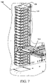
- FIG. 7 illustrates an exemplary automated library system portion in which aspects of the exemplary housing may be used.
- Exemplary systems and methods described herein relate generally to storage and manipulation of storage devices that may be contained in automated storage device library systems, and other systems and components such as media drives (for reading/writing data), magazines (for portable storage), fixed slots (for non-portable storage), and a transport station (for transporting storage devices to another library device such as an elevator or the like).
- media drives for reading/writing data
- magazines for portable storage
- fixed slots for non-portable storage
- transport station for transporting storage devices to another library device such as an elevator or the like.
- a storage device housing 100 capable of accepting multiple storage device types.
- the housing 100 includes an exemplary base 105 with an inner base surface 106 .
- Perimeter wall 115 extends from exemplary base 105 along first lateral side 107 , second lateral side 108 and rear side 109 .
- Perimeter wall 115 has an inner perimeter surface 116 and extends from base 105 substantially perpendicularly in some aspects. Perimeter wall 115 terminates at top edge 117 .
- Surfaces of portions of housing 100 have been separately identified (e.g., inner base surface 106 ) at least to indicate that such surfaces may be provided using a variety of different physical designs and vice versa (e.g., base 105 may have a different overall shape).
- a height of top edge 117 above inner base surface 106 is sized to a height of a first storage device type.
- a storage device of the first storage device type inserted from front side 110 into housing 100 may have a top surface that is approximately even with top edge 117 (as further described herein).
- inner perimeter surface 116 defines an interior space 120 (the space partially enclosed by inner perimeter surface 116 and inner base surface 106 ). In this example, interior space 120 remains open at front side 110 .
- Housing 100 is illustrated without a cover so that features and elements discussed may be illustrated more effectively; in practice a cover may be disposed at top edge 117 .
- the cover may be secured by pins 118 a - f. Element numbers used in this figure and other figures may point to only a portion of the entire element referenced (for example, exemplary top edge 117 extends along first lateral side 107 , rear side 109 , and second lateral side 108 , but is only referenced at rear side 109 ).
- Each of base 105 and perimeter wall 115 may be formed as a single piece of material (such as a plastic or a metal) or may be formed from multiple pieces of one or more materials. Also, base 105 and perimeter wall 115 may be formed unitarily (e.g., in a molding process). Further, a portion of base 105 and a portion of perimeter wall 115 may be formed unitarily (e.g., a bisection from a middle of front side 110 to a middle of rear side 109 may be molded separately) and joined with one or more remaining portions of housing 100 . Certain features are illustrated in FIG. 1 , such as central hole 190 formed in base 105 . These features are exemplary of a specific design and may be modified or in some cases eliminated, as one of skill in the art would comprehend. Other features may also be added, such as another hole in perimeter wall 115 or in base 105 .
- Stand-offs 125 a , 125 b are illustrated as protruding from perimeter wall 115 at rear side 109 (i.e., from inner perimeter surface 116 in this aspect). Stand-offs 125 a , 125 b may be selected based on which types of storage devices the housing is expected to accommodate. Stand-offs 125 a , 125 b may be positioned and shaped for mating or fitting within corresponding notches of a rear wall of a first storage device type and to avoid mating or fitting in notching of a second storage device type, such that stand-offs 125 a , 125 b may contact (abut) a rear wall of the second storage device type.
- Notching may include indentations, holes, slots, cutouts, and the like.
- stand-offs 125 a , 125 b permit the rear wall of the first storage device to be positioned closer to perimeter wall 115 , such that both storage device types may be positioned at a comparable pick point relative to front side 110 .
- Stand-offs 125 a , 125 b is an example of a length differentiating feature; other designs may be produced, as will be discussed below.
- housing 100 includes upper detent 140 and lower detent 145 .
- Each of upper detent 140 and lower detent 145 may be disposed to interact with storage devices of one or more storage device types and may be further disposed to avoid interacting with storage devices of types that interact with the other detent.
- upper detent 140 may be disposed to interact with the first storage device type and to avoid interacting with the second storage device type while lower detent 145 may be disposed to interact with the second storage device type and to avoid interacting with the first storage device type.
- Characteristics of each storage device type may be used to identify one or more appropriate dispositions for each detent.
- detent 140 is disposed somewhat closer to rear side 109 than detent 145 .
- Other aspects of the dispositions of detent 140 and detent 145 will become apparent with further reference to other figures.
- upper detent 140 and/or lower detent 145 may be modified and respective dispositions selected such that upper detent 140 and/or lower detent 145 may function as a length differentiating feature such that storage devices of the first storage device type and of the second storage device type are disposed at a common pick point (as will be further explicated herein).
- perimeter wall 115 may have an open rear side, such that housing 100 is shaped like a U with base 105 , first lateral side 107 , and second lateral side 108 .
- Exemplary housing 100 also includes indentations 131 a , 131 b formed in top edge 117 of perimeter wall 115 . A use for these indentations is further discussed herein. Compositions of elements and features discussed above may also be referred to as shells and slot bodies, or names indicative of an intended purpose for housing 100 in a particular library system.
- Two exemplary arms 230 a , 230 b are respectively coupled to perimeter wall 115 in indentations 131 a , 131 b formed from top edge 117 and extending from perimeter wall 115 .
- exemplary arm 230 b is coupled to first lateral side 107 and arm 230 a is coupled to second lateral side 108 .
- arm 230 a and arm 230 b are in a biased position, which causes at least an end portion 232 a of arm 230 a and an end portion 232 b of arm 230 b to extend into a portion of interior space 120 .
- Each arm 230 a , 230 b is configured to rotate from the illustrated biased position toward its respective indentation 131 a and 131 b (e.g., arm 230 a is coupled along second lateral side 108 and thus end portion 232 a of arm 230 a may rotate toward indentation 131 a formed in second lateral side 108 and from the portion of interior space 120 which the end portion 232 a occupies in the biased position).
- each arm 230 a , 230 b couples to perimeter wall 115 to locate respective end portion 232 a , 232 b at a predetermined height above inner base surface 106 .
- the height of each end portion 232 a , 232 b is selected based on heights (thicknesses) of storage device types that may be inserted into the housing (i.e., into interior space 120 ). More particularly, the height of each end portion 232 a , 232 b above base surface 106 may be selected to match a thickness of a smaller height (thinner) storage device of two storage device types (i.e., selected to match a thinner of two storage devices).
- such a thinner storage device would be insertable in housing 100 without pushing on arms 230 a , 230 b ; and if such a thinner storage device were to be inserted, arms 230 a , 230 b would help secure that thinner storage device by remaining in a biased position over a top surface of the thinner storage device. If a storage device thicker than the thinner storage device were to be inserted, then the thicker storage device would push arms 230 a , 230 b and as the thicker storage device continued to be inserted, arms 230 a , 230 b would rotate from interior space 120 in response to the pushing, and permit the thicker storage device to be fully inserted. It is to be understood that if base surface 106 were not flat, one of skill in the art would select a height for end portions 232 a , 232 b biased on a height differential of the portion upon which a storage device would rest when inserted.
- arms 230 a , 230 b extend substantially parallel to base surface 106 from perimeter wall 115 and arm 230 a is biased by torsion spring 260 a while arm 230 b is biased by torsion spring 260 b .
- each arm 230 a and 230 b may be coupled to perimeter wall 115 in a window in perimeter wall 115 , rather than in indentations 131 ab formed in top edge 117 .
- arms 230 a , 230 b may be coupled and biased to rotate through a larger arc than illustrated in FIG. 2 .
- arms 230 a , 230 b were coupled to perimeter wall as illustrated in FIG.
- end portions 232 a , 232 b would swing through a greater arc in response to a storage device pushing on each arm 230 a , 230 b while being inserted from front side 110 .
- Arms 230 a , 230 b may each also be disposed at some angle with respect to base surface 106 .
- One of skill in the art would understand that other ways to bias arms 230 a , 230 b other than torsion springs exist, and that torsion spring biasing is merely an example.
- arms 230 a , 230 b may be coupled to perimeter wall 115 to rotate in a plane different from described above (substantially parallel to base surface 106 ).
- arms 230 a , 230 b may be adapted to permit loading a storage device from the open top defined on three sides by top edge 117 of perimeter wall 115 .
- Such adaptation would include mounting arms 230 a , 230 b to rotate from an extended position down towards base 106 and inwards towards the respective portion of perimeter wall 115 to which each arm 230 a , 230 b is mounted.
- the arms 230 a , 230 b Upon inserting a storage device from the open top and upon clearing arms 230 a , 230 b , the arms 230 a , 230 b would be biased to return to an extended position and thereby aid in securing the storage device in housing 100 . Interaction between storage devices of various types and housing 100 will be further described herein.
- arms 230 a , 230 b may be coupled to a cover disposed at top edge 117 (see above). Arms 230 a , 230 b may be spring biased into interior space 120 and continue to a predetermined height above inner base surface 106 selected based on heights (thicknesses) of storage device types that may be inserted into the housing (i.e., into interior space 120 ). The predetermined height may be selected for permitting insertion of a thinner storage device without pushing on arms 230 a , 230 b . In such aspects, storage devices may be inserted from front side 110 . The predetermined height may be further selected so that arms 230 a , 230 b secure the thinner cartridge in the housing 100 after insertion. A storage device thicker than the thinner storage device, upon insertion would push on arms 230 a and 230 b , thereby causing them to rotate away from interior space 120 and toward the cover, and permitting the thicker storage device to be fully inserted into the cartridge.
- an arm may be disposed proximate top edge 117 and substantially parallel to front 110 from first lateral side 107 to second lateral side 108 .
- top edge 117 may be smooth (i.e., without indentations).
- the arm may be biased by an extension spring for a disposition near front 110 , the disposition also providing for insertion of a thinner cartridge without pushing on the arm.
- the arm Upon insertion of a cartridge thicker than the thinner cartridge, the arm evacuates the interior space 120 by sliding towards rear side 109 upon urging of the thicker cartridge.
- Extension springs may be provided at top edge 117 at both first lateral side 107 and second lateral side 108 .
- Compression springs may also be used, if disposed to compress towards rear side 109 , as one of skill in the art would comprehend.
- Guide structures may also be formed at top edge 117 or similar location to guide any such springs.
- such an arm may also be configured to rotate from the interior space, where the axis of rotation is parallel to front 110 .
- Torsion springs may be disposed at top edge 117 at both first lateral side 107 and second lateral side 108 to bias an arm of such an aspect.
- FIG. 3 illustrates an exemplary first cartridge type 300 (a type of storage device) that may be inserted into housing 100 .
- This cartridge includes certain features useful for illustrating various aspects that may be applied with regard to housing a variety of cartridge types.
- Cartridge 300 includes front 305 , left side 310 , top 315 , rear 320 , cutout 325 , and indentation (mating feature) 330 .
- Height 335 (thickness), width 340 , and length 345 dimensions of first cartridge type 300 are illustrated.
- LTO cartridges typically have features of illustrated cartridge type 300 .
- FIG. 4 illustrates an exemplary second cartridge type 400 that may be inserted into housing 100 .
- This cartridge type also includes certain features useful for illustrating various aspects that may be applied in housing a variety of cartridge types.
- Cartridge 400 includes front 405 , left side 410 , top 415 , rear 420 , and cutout (mating feature) 425 .
- Height 435 (thickness), width 440 , and length 445 dimensions of second cartridge type 400 are illustrated.
- first cartridge type 300 is thinner (smaller in a height dimension) and shorter (smaller in a length dimension) than second cartridge type 400 .
- SDLT cartridges typically have features of illustrated cartridge type 400 .
- FIG. 5 illustrates a top view of housing 100 having inserted therein a cartridge 500 of first cartridge type 300 .
- Cartridge 500 includes features of cartridge type 300 . Some of these features are illustrated and some are obscured by housing 100 .
- One feature visible is cutout 525 ( 325 for exemplary cartridge type 300 ). Certain features of housing 100 are also visible while others are obscured.
- arm ends 232 a and 232 b maintain a biased position over top 515 and aid in securing cartridge 500 within housing 100 .
- stand-offs 125 a , 125 b which keep rear 520 of cartridge 500 a predetermined distance from perimeter wall 115 of housing 100 by resisting against rear 520 .
- Upper detent 140 is visible within cutout 525 , while lower detent 145 is within an indentation (corresponding to indentation 330 ) not illustrated. Thus, upper detent 140 is positioned within cutout 525 and so avoids interaction with cartridge 500 .
- FIG. 6 illustrates a top view of housing 100 having inserted therein a cartridge 600 of second cartridge type 400 .
- Cartridge 600 includes aspects of cartridge type 400 , some of which are illustrated and some of which are obscured by housing 100 . Certain features of housing 100 are also visible while others are obscured. Because cartridge 600 is of exemplary thicker and longer cartridge type 400 , aspects relating to stand-offs 125 a , 125 b are further described here.
- arms 230 a , 230 b no longer remain biased into interior space 120 but have instead been rotated into respective indentations 131 a , 131 b (not illustrated in FIG. 6 ), thereby permitting thicker (taller) cartridge 600 to be inserted into housing 100 .
- Stand-offs 125 a , 125 b are no longer visible.
- Stand-offs 125 a , 125 b being disposed to match indentations on rear 620 of cartridge 600 , do not interfere with cartridge 600 being fully inserted into housing 100 , thereby permitting front 505 of cartridge 500 and front 605 of cartridge 600 to be disposed in approximately the same position relative to front 110 of housing 100 .
- stand-offs 125 a , 125 b permit a common pick point for cartridges 500 and 600 when inserted into housing 100 .
- the pick point may be defined as a point and a range of points around that point.
- the pick point may also be defined by a range of points functionally dictated by picking equipment expected to retrieve cartridges from housing 100 . For example, if particular picking equipment has ability to tolerate a wider range of cartridge placement, then a pick point may be defined with a greater margin of error.
- Upper detent 140 (general location illustrated) is also no longer visible, being obscured by top 605 . Upper detent 140 helps secure cartridge 600 in housing 100 . Referring to FIGS. 2 and 4 , lower detent 145 is disposed at cutout 425 (not illustrated in FIG. 6 ). Thus, lower detent 145 is disposed to avoid interacting with cartridge 600 while upper detent 140 helps retain cartridge 600 in housing 100 . Lower detent 145 may be formed to provide flexibility of movement such that cartridge 600 being inserted into the housing may push lower detent 145 out of the way during insertion.
- Lower detent 145 may also be formed to fit within a cutout portion of cartridge 600 (of cartridge type 400 ) such that after cartridge 600 is inserted, lower detent 145 fits within the notch and does not obstruct insertion of cartridge 600 . Also, lower detent 145 may be formed with a sufficiently sloping end to permit retrieving cartridge 600 from housing 100 if cartridge 600 is pulled from near its front 605 . A sufficient slope of the end provides for lower detent 145 to be pushed away from cartridge 600 as pulling force is applied to cartridge 600 (i.e., lower detent 145 is flexible enough to be pushed out of the way during retrieval of cartridge 600 from housing 100 ). As discussed above, upper detent 140 and lower detent 145 may be further modified and disposed to provide for disposition of cartridge 500 and cartridge 600 at the pick point, rather than (or in addition to) using a length differentiating feature disposed at rear side 109 .
- housing 100 may be disposed at different heights above base surface 106 to accommodate still further variations in thickness among storage device types.
- Other stand-offs with other lengths may be positioned at other appropriate points on perimeter wall 115 to accommodate still further variations in length among storage device types.
- Such aspects may also be employed in designing future storage device types to ease compatibility amongst storage device types for storage in a common housing.
- FIG. 7 illustrates a portion of one of many exemplary systems in which exemplary housing 100 may be used.
- housing 100 may be replicated a number of times to provide slots (such as slot 710 ) for a number of storage devices, such as cartridges 500 , 600 .
- slot 710 may accommodate a variety of storage device types.
- Picker 705 retrieves cartridges 500 , 600 (i.e., cartridges of different types stored in housing 100 ) from slot 710 . Because a variety of storage device types may be disposed in any given slot, versatility of system 700 is improved.
- Housing 100 may be used to provide fixed slots, pass-thrus, pickers and magazines and the like, which are all known by those of skill in the art who would be able to apply aspects described herein to produce universal-type housings useful for all such types.
- a method for forming a cartridge library system may include providing a plurality of universal housings (e.g., housing 100 ) in a regular configuration appropriate for a desire library system type (e.g., a magazine), the universal housings having height differentiation features and length differentiating features according to any inventive aspect described above.
- the method may further include providing cartridge retrieval robotics known in the art appropriate for the desired library system type.
Abstract
Description
Claims (27)
Priority Applications (4)
| Application Number | Priority Date | Filing Date | Title |
|---|---|---|---|
| US11/105,883 US7486473B2 (en) | 2005-04-13 | 2005-04-13 | Universal housing for holding storage devices |
| JP2006108827A JP2006294039A (en) | 2005-04-13 | 2006-04-11 | Housing for holding storage device and data storage library system |
| EP06252028A EP1713073B1 (en) | 2005-04-13 | 2006-04-12 | Universal housing for holding storage devices |
| DE602006000506T DE602006000506T2 (en) | 2005-04-13 | 2006-04-12 | Universal housing for holding storage devices |
Applications Claiming Priority (1)
| Application Number | Priority Date | Filing Date | Title |
|---|---|---|---|
| US11/105,883 US7486473B2 (en) | 2005-04-13 | 2005-04-13 | Universal housing for holding storage devices |
Publications (2)
| Publication Number | Publication Date |
|---|---|
| US20060231513A1 US20060231513A1 (en) | 2006-10-19 |
| US7486473B2 true US7486473B2 (en) | 2009-02-03 |
Family
ID=36603640
Family Applications (1)
| Application Number | Title | Priority Date | Filing Date |
|---|---|---|---|
| US11/105,883 Expired - Fee Related US7486473B2 (en) | 2005-04-13 | 2005-04-13 | Universal housing for holding storage devices |
Country Status (4)
| Country | Link |
|---|---|
| US (1) | US7486473B2 (en) |
| EP (1) | EP1713073B1 (en) |
| JP (1) | JP2006294039A (en) |
| DE (1) | DE602006000506T2 (en) |
Cited By (1)
| Publication number | Priority date | Publication date | Assignee | Title |
|---|---|---|---|---|
| US20160012830A1 (en) * | 2012-09-07 | 2016-01-14 | International Business Machines Corporation | Reduced friction retention of a data storage cartridge within a storage cell |
Families Citing this family (2)
| Publication number | Priority date | Publication date | Assignee | Title |
|---|---|---|---|---|
| US8159623B2 (en) * | 2007-12-31 | 2012-04-17 | Honda Motor Co., Ltd. | Remote control dock system and method |
| US8139315B2 (en) * | 2008-06-27 | 2012-03-20 | International Business Machines Corporation | Storage slot for data storage cartridges of differing dimensions |
Citations (13)
| Publication number | Priority date | Publication date | Assignee | Title |
|---|---|---|---|---|
| US3735989A (en) * | 1972-05-12 | 1973-05-29 | Motorola Inc | Cartridge locking mechanism with adjustable tension |
| US5692623A (en) * | 1995-12-20 | 1997-12-02 | Storage Technology Corporation | Storage array for presenting tape media of differing dimensions to a robotic arm at a common datum |
| US5936795A (en) * | 1997-03-05 | 1999-08-10 | Seagate Technology, Inc. | Magazine cassette locking device |
| GB2352865A (en) * | 1999-05-17 | 2001-02-07 | Hewlett Packard Co | Picker indexing and multimedia cartridge referencing spring |
| US6244677B1 (en) * | 1999-07-28 | 2001-06-12 | Storage Technology Corporation | Array and method for standardizing cartridge location within storage cells of a data storage library |
| US20020006030A1 (en) * | 2000-04-06 | 2002-01-17 | Evanson Daniel R. | Universal media module |
| EP1235217A1 (en) | 2001-02-22 | 2002-08-28 | Hewlett-Packard Company, A Delaware Corporation | Apparatus and method for retaining different sizes of data cartridges in a storage magazine |
| US6526017B1 (en) * | 2000-04-28 | 2003-02-25 | Hewlett-Packard Company | Media cartridge retention and ejection system |
| US20030058747A1 (en) | 2001-09-24 | 2003-03-27 | Smith Mark A. | Universal cartridge magazine system and method |
| US20030146127A1 (en) | 1998-11-12 | 2003-08-07 | Fuji Photo Film Co., Ltd. | Cassette storing case |
| US20040012878A1 (en) | 2002-07-16 | 2004-01-22 | Fujitsu Limited | Robot hand and library apparatus |
| US6771457B2 (en) * | 2002-08-01 | 2004-08-03 | International Business Machines Corporation | Toggle-protrusion lockout mechanism for cartridge library |
| US20040190177A1 (en) * | 2003-03-27 | 2004-09-30 | Christie Leslie G. | Media-detection system and method for identifying types of data cartridges |
Family Cites Families (1)
| Publication number | Priority date | Publication date | Assignee | Title |
|---|---|---|---|---|
| US6596833B2 (en) * | 2000-03-14 | 2003-07-22 | Chisso Corporation | Carbosilane and polycarbosilane |
-
2005
- 2005-04-13 US US11/105,883 patent/US7486473B2/en not_active Expired - Fee Related
-
2006
- 2006-04-11 JP JP2006108827A patent/JP2006294039A/en not_active Withdrawn
- 2006-04-12 EP EP06252028A patent/EP1713073B1/en not_active Expired - Fee Related
- 2006-04-12 DE DE602006000506T patent/DE602006000506T2/en not_active Expired - Fee Related
Patent Citations (15)
| Publication number | Priority date | Publication date | Assignee | Title |
|---|---|---|---|---|
| US3735989A (en) * | 1972-05-12 | 1973-05-29 | Motorola Inc | Cartridge locking mechanism with adjustable tension |
| US5692623A (en) * | 1995-12-20 | 1997-12-02 | Storage Technology Corporation | Storage array for presenting tape media of differing dimensions to a robotic arm at a common datum |
| US5936795A (en) * | 1997-03-05 | 1999-08-10 | Seagate Technology, Inc. | Magazine cassette locking device |
| US20030146127A1 (en) | 1998-11-12 | 2003-08-07 | Fuji Photo Film Co., Ltd. | Cassette storing case |
| GB2352865A (en) * | 1999-05-17 | 2001-02-07 | Hewlett Packard Co | Picker indexing and multimedia cartridge referencing spring |
| US6244677B1 (en) * | 1999-07-28 | 2001-06-12 | Storage Technology Corporation | Array and method for standardizing cartridge location within storage cells of a data storage library |
| US20020006030A1 (en) * | 2000-04-06 | 2002-01-17 | Evanson Daniel R. | Universal media module |
| US6526017B1 (en) * | 2000-04-28 | 2003-02-25 | Hewlett-Packard Company | Media cartridge retention and ejection system |
| EP1235217A1 (en) | 2001-02-22 | 2002-08-28 | Hewlett-Packard Company, A Delaware Corporation | Apparatus and method for retaining different sizes of data cartridges in a storage magazine |
| US20030058747A1 (en) | 2001-09-24 | 2003-03-27 | Smith Mark A. | Universal cartridge magazine system and method |
| US7019940B2 (en) * | 2001-09-24 | 2006-03-28 | Hewlett-Packard Development Company, L.P. | Universal cartridge magazine system and method |
| US20040012878A1 (en) | 2002-07-16 | 2004-01-22 | Fujitsu Limited | Robot hand and library apparatus |
| US6771457B2 (en) * | 2002-08-01 | 2004-08-03 | International Business Machines Corporation | Toggle-protrusion lockout mechanism for cartridge library |
| US20040190177A1 (en) * | 2003-03-27 | 2004-09-30 | Christie Leslie G. | Media-detection system and method for identifying types of data cartridges |
| US7006319B2 (en) * | 2003-03-27 | 2006-02-28 | Hewlett-Packard Development Company, L.P. | Media-detection system and method for identifying types of data cartridges |
Cited By (5)
| Publication number | Priority date | Publication date | Assignee | Title |
|---|---|---|---|---|
| US20160012830A1 (en) * | 2012-09-07 | 2016-01-14 | International Business Machines Corporation | Reduced friction retention of a data storage cartridge within a storage cell |
| US9355652B2 (en) | 2012-09-07 | 2016-05-31 | International Business Machines Corporation | Reduced friction retention of a data storage cartridge within a storage cell |
| US9390730B2 (en) * | 2012-09-07 | 2016-07-12 | International Business Machines Corporation | Reduced friction retention of a data storage cartridge within a storage cell |
| US9918402B2 (en) | 2012-09-07 | 2018-03-13 | International Business Machines Corporation | Reduced friction retention of a data storage cartridge within a storage cell |
| US10566029B2 (en) | 2012-09-07 | 2020-02-18 | International Business Machines Corporation | Reduced friction retention of a data storage cartridge within a storage cell |
Also Published As
| Publication number | Publication date |
|---|---|
| US20060231513A1 (en) | 2006-10-19 |
| DE602006000506T2 (en) | 2009-01-29 |
| JP2006294039A (en) | 2006-10-26 |
| EP1713073A1 (en) | 2006-10-18 |
| DE602006000506D1 (en) | 2008-03-20 |
| EP1713073B1 (en) | 2008-02-06 |
Similar Documents
| Publication | Publication Date | Title |
|---|---|---|
| US5682276A (en) | Data cartridge library system architecture | |
| US7474497B2 (en) | Deep slot magazine storage library | |
| US6781789B2 (en) | Dual cartridges storage array cell for data storage | |
| JPH08212745A (en) | Disk cartridge magazine | |
| JPH08263907A (en) | Pass-through cassette magazine,handling method of storage medium and automatic storage system | |
| US20020006030A1 (en) | Universal media module | |
| US7486473B2 (en) | Universal housing for holding storage devices | |
| US6042205A (en) | Media holding device incorporating a media locking mechanism | |
| US5926341A (en) | Data cartridge interlock and release system | |
| US5927834A (en) | Receiver and magazine assembly for storage library system | |
| US6473261B1 (en) | Cartridge overinsertion protection for cartridge library | |
| US7580220B1 (en) | Cartridge magazine with pivoting cartridge retention mechanism | |
| US5687039A (en) | Dual fixed-finger picker for data cartridges | |
| US8516513B2 (en) | Cassette with disk eject mechanism | |
| US6155659A (en) | Receiver and magazine assembly for storage library system | |
| WO1998057328A1 (en) | Case for packaging and storing a magnetic disk cartridge | |
| US6526017B1 (en) | Media cartridge retention and ejection system | |
| GB2290779A (en) | Memory card holder | |
| EP1150290B1 (en) | Apparatus for handling media cartridges | |
| US7274531B2 (en) | Extendable storage bin mounting for automatic storage library | |
| JP2005518625A (en) | Data cartridge case adapted for dual format applications | |
| JP2019071154A (en) | Disk device | |
| US20030075006A1 (en) | Device for limiting movement of a body in relation to another | |
| US5143209A (en) | Automatic extension cassette container | |
| US7293733B2 (en) | Integrated reel locking device for media cartridge and associated methods of manufacture |
Legal Events
| Date | Code | Title | Description |
|---|---|---|---|
| AS | Assignment |
Owner name: QUANTUM CORPORATION, CALIFORNIA Free format text: ASSIGNMENT OF ASSIGNORS INTEREST;ASSIGNORS:THORSON, THOMAS A.;COLLINS, PADDY E.;REEL/FRAME:016481/0779 Effective date: 20050411 |
|
| AS | Assignment |
Owner name: WELLS FARGO CAPITAL FINANCE, LLC, AS AGENT, CALIFO Free format text: SECURITY AGREEMENT;ASSIGNOR:QUANTUM CORPORATION;REEL/FRAME:027967/0914 Effective date: 20120329 |
|
| FPAY | Fee payment |
Year of fee payment: 4 |
|
| FEPP | Fee payment procedure |
Free format text: PAYOR NUMBER ASSIGNED (ORIGINAL EVENT CODE: ASPN); ENTITY STATUS OF PATENT OWNER: LARGE ENTITY |
|
| REMI | Maintenance fee reminder mailed | ||
| AS | Assignment |
Owner name: TCW ASSET MANAGEMENT COMPANY LLC, AS AGENT, MASSACHUSETTS Free format text: SECURITY INTEREST;ASSIGNOR:QUANTUM CORPORATION;REEL/FRAME:040451/0183 Effective date: 20161021 Owner name: TCW ASSET MANAGEMENT COMPANY LLC, AS AGENT, MASSAC Free format text: SECURITY INTEREST;ASSIGNOR:QUANTUM CORPORATION;REEL/FRAME:040451/0183 Effective date: 20161021 |
|
| AS | Assignment |
Owner name: PNC BANK, NATIONAL ASSOCIATION, PENNSYLVANIA Free format text: SECURITY INTEREST;ASSIGNOR:QUANTUM CORPORATION;REEL/FRAME:040473/0378 Effective date: 20161021 Owner name: QUANTUM CORPORATION, CALIFORNIA Free format text: RELEASE BY SECURED PARTY;ASSIGNOR:WELLS FARGO CAPITAL FINANCE, LLC, AS AGENT;REEL/FRAME:040474/0079 Effective date: 20161021 |
|
| LAPS | Lapse for failure to pay maintenance fees | ||
| STCH | Information on status: patent discontinuation |
Free format text: PATENT EXPIRED DUE TO NONPAYMENT OF MAINTENANCE FEES UNDER 37 CFR 1.362 |
|
| FP | Lapsed due to failure to pay maintenance fee |
Effective date: 20170203 |
|
| AS | Assignment |
Owner name: QUANTUM CORPORATION, CALIFORNIA Free format text: RELEASE BY SECURED PARTY;ASSIGNOR:TCW ASSET MANAGEMENT COMPANY LLC, AS AGENT;REEL/FRAME:047988/0642 Effective date: 20181227 |