JP3760133B2 - How to add lifting equipment for dwelling unit access - Google Patents
How to add lifting equipment for dwelling unit access Download PDFInfo
- Publication number
- JP3760133B2 JP3760133B2 JP2002028685A JP2002028685A JP3760133B2 JP 3760133 B2 JP3760133 B2 JP 3760133B2 JP 2002028685 A JP2002028685 A JP 2002028685A JP 2002028685 A JP2002028685 A JP 2002028685A JP 3760133 B2 JP3760133 B2 JP 3760133B2
- Authority
- JP
- Japan
- Prior art keywords
- staircase
- floor
- apartment house
- passage
- type apartment
- Prior art date
- Legal status (The legal status is an assumption and is not a legal conclusion. Google has not performed a legal analysis and makes no representation as to the accuracy of the status listed.)
- Expired - Fee Related
Links
Images


Classifications
-
- E—FIXED CONSTRUCTIONS
- E04—BUILDING
- E04G—SCAFFOLDING; FORMS; SHUTTERING; BUILDING IMPLEMENTS OR AIDS, OR THEIR USE; HANDLING BUILDING MATERIALS ON THE SITE; REPAIRING, BREAKING-UP OR OTHER WORK ON EXISTING BUILDINGS
- E04G23/00—Working measures on existing buildings
- E04G23/02—Repairing, e.g. filling cracks; Restoring; Altering; Enlarging
- E04G23/0266—Enlarging
Description
【0001】
【発明の属する技術分野】
本発明は、階段昇降型の低・中層集合住宅を対象として、特に高齢者が容易に上り下りできるようにエレベーター等の機械昇降設備を既存建物に増設するための増設方法に関する。
【0002】
【従来の技術】
現在、日本の高齢化率は世界的にも高い数値にあり、高齢化が急速に進まりつつある。このような状況の中、高齢者でも自宅で快適に生活が送れるように、高齢者向けのバリヤフリー住宅が盛んに提案されている。
【0003】
一方、特に都市部では、これまでに宅地用の土地不足から、いわゆるマンション型式の低・中層の集合住宅が多く建設されてきた。このような低・中層住宅は、各階段室の両側にそれぞれ玄関口を有する、所謂「階段室型集合住宅」の住宅が多い。
【0004】
現在、既存建物の改装に当たっては、十数年先の高齢化社会を見据え、隣室境界に段差を有しないなどのバリヤフリー化が行われているが、エレベータ等の昇降設備を有しない前記階段昇降型の低・中層集合住宅の場合には、内装の改修とは別に、高齢者が簡単にアクセスできるように、エレベータなどの機械昇降設備を増設することが強く望まれている。
【0005】
このような要望に応えるべく、図15に示されるように、集合住宅40の隣接位置にエレベータ設備41を構築するとともに、階段室の踊り場42から前記エレベータ設備41に連絡する連絡通路43を各階毎に設けた事例(従来例1)が幾つか報告されている。
【0006】
しかし、この昇降設備の増設方法の場合は、踊り場42まで階段を利用しなければならず、完全なバリヤフリー化を実現することができないなどの問題があった。
【0007】
このような問題を解決すべく、特開平11-159153号公報においては、図16および図17に示されるようなエレベーターの増設方法(従来例2)が提案されている。
【0008】
具体的には、階段室型集合住宅50とは別にその隣接位置に対し住戸アクセス用機械昇降設備52を構築し、前記階段室型集合住宅50において、階段51および踊り場56を撤去するとともに、既設階段室床版55に連続して既設階段室床版55および躯体側壁に支持された床版54を増設し、かつこの増設床版54より前記住戸アクセス用機械昇降設備52に接続される外部廊下53を設けるようにするもので、さらに前記外部廊下53は基礎工事を不要とするため、柱によって連結されることなく各階毎に独立とされ、隣接する同一階の各増設床版54から外側に張り出した各張出し通路部53Aと、これら各張出し通路部53A間に梁部材57を渡して設置された一般通路部53Bとから構成するようにしている。
【0009】
また、特開2001-279934号公報においては、図18および図19に示されるような既存建物へのエレベーターの構築方法(従来例3)が提案されている。
【0010】
具体的には、既存の集合住宅60の外部の階段室61の隣接位置に対し住戸アクセス用機械昇降設備62を構築し、既存の集合住宅の各階の床版65に連続して前記住戸アクセス用機械昇降設備62に接続される新設床63を設けるものであり、その施工方法は前記住戸アクセス用機械昇降設備62を前記既存の集合住宅60に近接させ階段室61の外側に先行設置した後、前記既存の集合住宅60の最上階より順に前記新設床63を敷設するとともに、階段を撤去するようにする。この場合、居住者の出入りは、新設床63の設置が完了するまでの間は、エレベータ構造物から張り出した床に連続して各住戸への仮設出入口66を設けることにより確保している。
【0011】
【発明が解決しようとする課題】
前記従来例2および従来例3に係る方法は、いずれも各階の階段室床版に連続して、機械昇降設備に接続される増設床版が設けられるので、完全なバリヤフリー化が実現されるようになる。
【0012】
しかしながら、前記従来例2による方法の場合は、同公報に記載されるように、確かに既存建物に与える影響を少なくしながら短期間に工事を終えることができるけれども、階段室の階段および踊り場を完全に撤去するため撤去工事負担が大きい。また、住人への影響を最小限に抑えながら工事を終えることができるけれども、この階段および踊り場の撤去工事中は片側通行などの通行規制が必要となるため居住者の通行に多少の支障が出ることになる。また、法令による規制から災害時の非常用階段を別途、外部通路側に設けなければならないなどの問題がある。
【0013】
一方、前記従来例3に係る方法は、最上階より下階側に向けて順に、新設床63を敷設した後、この新設床63の下側に存在する階段および踊り場を撤去するため、比較的住人への影響は少なくて済むようになるが、階段室の階段および踊り場を完全に撤去する点は従来例1と同様で、この撤去工事負担が大きいなどの問題がある。また、従来例3では、新設床の敷設工事中は、階段室が利用不可となるためエレベータ構造物から張出床を設け別途各住戸への仮設出入口を確保するようにしているが、この仮設出入口は住居のサッシ部分を出入り口とするものであり、住人にとって不便であることに変わりはない。また、法令による規制から災害時の非常用階段を別途、外部通路側に設けなければならない点は従来例1と同様である。
【0014】
そこで、本発明の主たる課題は、段差の無い完全なバリヤフリー化を実現するとともに、既設建築物に与える影響が少なく、工事を短期間に終えることができるなどの従来工法の利点に加えて、工事中においても各階の住人が通常通り玄関を出入口として使用できるようにするとともに、階段および踊り場の撤去工事負担が小さく、かつ新たに非常用階段を設ける必要がない等の利点を兼ね備えた階段室型集合住宅への機械昇降設備の増設方法を提供することにある。
【0015】
【課題を解決するための手段】
前記課題を解決するための請求項1に係る発明として、途中に踊り場を有する折返し階段を共用する階段室型集合住宅を対象として、
前記階段室型集合住宅とは別にその隣接位置に少なくとも1以上の住戸アクセス用機械昇降設備を構築し、かつ前記住戸アクセス用機械昇降設備に接続されるとともに、前記階段室型集合住宅の少なくとも2階以上の各階にそれぞれ対応する外部廊下を設け、
前記階段室型集合住宅の少なくとも2階以上の各階部分において、前記折返し階段の上り側または下り側に、前記階段室型集合住宅の階段室床版と前記外部廊下とを連絡する工場製作桁を用いた渡り通路を架け渡すとともに、この渡り通路の通行に障害となる既設の階段部分及び踊り場部分を撤去し、
前記折返し階段の踊り場と前記外部廊下との間に取付階段を設け、この取付階段と前記渡り通路が設けられていない利用可能な既設の上り側階段または下り側階段とにより上下階の連絡用階段を構成し、主たる住戸アクセス方法を前記折返し階段から機械昇降設備に変更するための住戸アクセス用昇降設備の増設方法であって、
前記階段室型集合住宅とは別にその隣接位置に対し少なくとも1以上の住戸アクセス用機械昇降設備と、前記住戸アクセス用機械昇降設備に接続されるとともに、前記階段室型集合住宅の少なくとも2階以上の各階にそれぞれ対応する外部廊下とを設ける第1工程と、
前記階段室型集合住宅の少なくとも2階以上の各階部分において、前記折返し階段の踊り場と前記外部廊下との間であってかつ前記折返し階段の上り側または下り側に取付階段を設ける第2工程と、
最上階から下階側にまたは2階より上階側に向けて順に、前記取付階段が設けられていない前記折返し階段の上り側または下り側に、前記階段室型集合住宅の階段室床版と前記外部廊下とを連絡する工場製作桁を用いた渡り通路を前記階段室床版から外部廊下に向かって下り勾配を付けて設置する作業と、渡り通路の通行に障害となる既設の階段部分及び踊り場部分を撤去する作業とを順に進めていくとともに、前記最上階については、前記渡り廊下を設置した後、その下側に位置する階段部分および踊り場部分を撤去する手順に従う第3工程と、からなることを特徴とする住戸アクセス用昇降設備の増設方法が提供される。
【0016】
上記請求項1記載の発明においては、住戸アクセス用機械昇降設備に接続される外部廊下とを構築し、既設階段室床版と前記外部廊下との間に段差を有しない渡り通路を設けるため、各階毎に完全なバリヤフリー化を実現することができるようになる。また、住戸アクセス用機械昇降設備は階段室型集合住宅とは別に構築するため、既設建築物に対する構造的影響が少なく、工事を短期間に終えることができるようになる。
【0017】
加えて、本発明では前記渡り通路を折返し階段の片側のみを占有して架け渡し、かつ前記階段の踊り場と前記外部廊下との間に取付階段を設け、この取付階段と前記渡り通路が設けられていない利用可能な既設の上り側階段または下り側階段とにより上下階の連絡用階段を構成するようにしている。したがって、工事階の住人は、通常通り玄関を出入口として使用しながら、工事中であっても前記渡り通路を利用して外部通路との行き来ができるようになる。また、既設の階段および踊り場は半分を残して非常用階段として利用するため、撤去工事負担が従来の半分以下の手間で済むようになるとともに、従来のように外部通路側に別途、非常階段を設置する必要が無くなるようになる。
また、渡り通路として工場製作桁を用いることにより、設置作業が短時間で済むようになり、住人への通行障害をほぼ無くすことができる。
【0018】
【発明の実施の形態】
以下、本発明の実施の形態について図面を参照しながら詳述する。
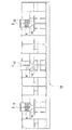
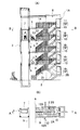
図1は昇降設備増設前の階段室型集合住宅1Aの平面図であり、図2は昇降設備増設後の集合住宅平面図、図3は昇降設備増設前の階段室型集合住宅を示す(A)は建物縦断面図((B)のA-A線矢視)、(B)はそのB−B線矢視図、以降の図4〜図10は施工手順図である。
【0019】
本発明の適用対象となる集合住宅は、図1に示されるように、各階複数戸、図示例では2戸で一つの階段室8を共用し、かつ住戸アクセス手段を途中に踊り場12を有する折返し階段2とする階段室型集合住宅1Aであり、主に階層5階までの低・中層住宅を対象とするものである。
【0020】
かかる階段室型集合住宅1A(以下、単に集合住宅という。)において、各住戸までの主たるアクセス手段を前記折返し階段2からエレベータ等の機械昇降設備に変更するために本発明が適用される。
【0021】
本機械昇降設備の増設方法では、図2に示されるように、集合住宅1Aの隣接位置に昇降自在のエレベータ7を内蔵したエレベータ設備3が構築されるとともに、このエレベータ設備3に接続されるとともに、集合住宅1Aの少なくとも2階以上の各階にそれぞれ対応する外部廊下5、5…が設けられる。また、集合住宅1Aの少なくとも2階以上の各階部分では、折返し階段2の下り側(符号2A側)に、階段室8の床版10と、前記外部廊下5とを連絡するとともに、かつ段差を有しない渡り通路6が架け渡され、渡り通路6が架け渡されていない側の踊り場12部分と前記外部廊下5との間に取付階段9が設けられ、この取付階段9と前記渡り通路6が設けられていない利用可能な既設の上り側階段2Bとにより上下階の連絡用階段が構成されている。なお、本明細書において、階段2の上り側または下り側は、各階の階段室床版10を基準に下り側か上り側かで判断する。
【0022】
以下具体的に、施工手順に従いながら昇降設備増設方法について詳述すると、先ず図3に示されるように、増設前の状態では、各玄関口11の前には階段室床版10、10…があり、下り階段2Aと上り階段2Bとからなる折返し階段2の途中には踊り場12が設けられている。
【0023】
機械昇降設備を増設するに際しては、まず第1工程として、図4に示されるように、集合住宅1Aとは別に、その隣接位置に独立的にエレベータ設備3を基礎工事3Aから行い構築する。図示例ではエレベータ設備3の上部において、集合住宅1Aと連結鋼材4、4により連結して補強を行っている。また、前記連結鋼材4,4を利用してフード20が設置されている。
【0024】
前記エレベータ設備3には、地上階を除く集合住宅1Aの各階に対応する高さ位置にそれぞれ外部廊下5,5…を前記エレベータ設備3より前記集合住宅1A側に張り出して構築する。この外部廊下5は、基礎から柱部材を建て、梁を渡して床を設置して構築される。なお、増設工事中は、前記エレベータ設備3を作業用昇降設備として使用することができるとともに、前記外部廊下5を作業用通路としながら作業を進めることができる。
【0025】
次に、図5に示されるように、地上階を除く上階部分において、前記踊り場12の室外側の手摺り壁を撤去し、前記踊り場12の上り階段側12Bより前記外部廊下5に連絡する取付階段9を設ける。この取付階段9には、通行者の落下防止のため手摺13を取り付けるようにする。
【0026】
前記エレベータ設備3の構築、外部廊下5の設置、取付階段9の設置を完了したならば、図6に示されるように、前記集合住宅1Aの最上階において、折返し階段2の下り側2Aに、階段室床版10と外部通路5とを連絡する渡り通路61を架け渡すようにする。この渡り通路61は、現場施工によるのではなく、予め工場によって製作された製作桁、例えば鉄骨梁およびデッキ床材からなる桁や、プレキャストコンクリート桁などを用い短時間で設置できるようにするのが望ましい。設置に当たっては、図示されるように、階段2の最上段踏み面をそのまま沓座面として設置することができる。この渡り通路61には手摺り14を設けるようにする。また、垂壁15は通行の邪魔になるため撤去する。
【0027】
前記渡り通路61を設置したならば、この渡り通路61の下側に位置する階段及び踊り場部分、すなわち5階から4階への下り階段部分2Aと、踊り場12の下り側部分12Aを撤去する。この撤去工事中は、5階の住人は前記渡り通路61を通って外部廊下5に行き来し、エレベータ設備3を使用して地上に降りることができる。また、4階の住人は取付階段9、上り側踊り場12B、上り側階段2Bを通って外部廊下5に行き来でき、エレベータ設備3により地上に降りることができる。特に、5階の住人はこの段階でバリヤフリーを実現できるようになっている。このように、本発明の場合は、増設工事中、工事階の住人であっても、通常通り、住居に住みながら玄関を出入口として生活することができる。なお、前記渡り廊下61の下面側に形成される、上り側踊り場12Bの側部開口は、塞ぎ格子22によって封鎖するようにする。
【0028】
なお、本例では極力、前記取付階段9の階段数を少なくするとともに、外部廊下5との離間距離を小さくするため、前記渡り通路6にある程度の勾配を設けるようにしているが、もちろん排水勾配を付ける程度の勾配としほぼ水平状態に設置するようにしてもよい。
【0029】
上記4階への下り階段部分2Aと、踊り場12の下り側部分12Aとの撤去工事を完了したならば、次に4階の工事に移る。図7に示されるように、5階における作業と同様に、折返し階段2の下り側2Aに、階段室床版10と外部通路5とを連絡する渡り通路62を架け渡した後、この渡り通路62の下側に位置する階段及び踊り場部分、すなわち3階への下り階段部分2Aと、踊り場12の下り側部分12Aを撤去する。
【0030】
以降は、図8および図9に示されるように、3階及び2階の順で同様の作業を繰り返す。図10は改築完成状態を示す縦断面図である。なお、2階に設置した渡り通路64の下面側に位置する階段及び踊り場部分、すなわち2階から1階への下り階段部分2Aと、踊り場12の下り側部分12Aは上階と同様に撤去してもよいが、撤去工事負担の軽減から好ましく撤去せずに、そのまま残置するのがよい。
【0031】
ところで、本発明では上記施工手順以外に、種々の変更が可能である。具体的には、
(1)上記形態例では最上階(5階)から下階側に順に工事を進めるようにしたが、施工順序は2階から上階側に向けて順に行うようにしてもよい。
【0032】
(2)上記形態例では、折返し階段2の下り側部分2Aに渡り通路6を設置したが、上り側に設置するようにしてもよい。この場合は、階段の踊り場12と外部廊下5とを連絡する取付階段9は、図11に示されるように、下階側の外部廊下5に対して接続するようにする。また、1階と2階の中間の踊り場12には地上階に接続する取付階段21を設けるようにする。なお、図11では、取付階段9の階段数を少なくするとともに、集合住宅1Aとエレベータ設備3との離間距離を小さくするため、外部廊下5と階段室床版10とはほぼ同一レベルとしている。
【0033】
(3)上記形態例では、各階すべてにおいて、渡り通路6を設置した後、その下側に位置する階段および踊り場部分を撤去するようにしたが、最上階の5階については5階住人のアクセス手段を確保するため、渡り通路6を設置した後、その下側に位置する階段および踊り場部分を撤去する手順に従うが、その他の階では下り側の階段及び踊り場を撤去した後、渡り通路6を設置するようにしてもよい。
【0034】
以上、上記形態例では階段室8が3つとし、1つの階に6住戸が居住している集合住宅1の例であるが、エレベータ設備3の設置数および外部廊下5の形成態様については集合住宅の住居数/階に応じて任意のパターンが考えられる。図12に示される例は、階段室8が2つの集合住宅1Bの場合のパターン例である。図13に示される例は、階段室8が4つの集合住宅1Cのパターン例であり、図13(A)の例はエレベーターの混雑を緩和すべく、2つの階段室を一組としてエレベータ設備3、3を配置したパターン例であり、図13(B)の例は4つの階段室8を1つの外部廊下5と接続し、1つのエレベータ設備3で共用するパターン例である。
【0035】
更に図14に示される例は、階段室8が5つの集合住宅1Dの例であり、図14(A)は3つの階段室8を一組とし、かつ2つの階段室8を一組としてそれぞれにエレベータ設備3を配置したパターン例であり、図14(B)の例は5つの階段室8を1つの外部廊下5と接続し、1つのエレベータ設備3で共用するパターン例である。
【0036】
【発明の効果】
以上詳説のとおり本発明によれば、段差の無い完全なバリヤフリー化を実現するとともに、既設建築物に与える影響が少なく、工事を短期間に終えることができるなどの従来工法の利点に加えて、工事中においても各階の住人が通常通り玄関を出入口として使用できるようになるとともに、既設の階段および踊り場の内、半分をそのまま残置するため撤去工事負担が小さくなる。また、居住者への工事騒音等の影響を軽減できるようになる。
【0037】
更に、新たに残置した既設の階段および踊り場部分を非常用階段として利用するため、外部廊下側に別途、非常階段を設ける必要がないなどの利点を兼ね備えたものとなる。
【図面の簡単な説明】
【図1】 昇降設備増設前の階段室型集合住宅の平面図である。
【図2】 昇降設備増設後の集合住宅平面図である。
【図3】 昇降設備増設前の階段室型集合住宅を示す(A)は建物縦断面図、(B)はB−B線矢視図である。
【図4】 施工手順図(その1)で、エレベータ設備3及び外部廊下5を構築した状態を示す、(A)は建物縦断面図((B)のA-A線矢視)、(B)はそのB-B線矢視図である。
【図5】 施工手順図(その2)で、取付階段9を設けた状態を示す、(A)は建物縦断面図((B)のA-A線矢視)、(B)はそのB-B線矢視図である。
【図6】 施工手順図(その3)で、最上階(5階)に渡り通路6を設置した状態を示す、(A)は建物縦断面図((B)のA-A線矢視)、(B)はそのB-B線矢視図である。
【図7】 施工手順図(その4)で、4階に渡り通路6を設置した状態を示す建物縦断面図である。
【図8】 施工手順図(その5)で、3階に渡り通路6を設置した状態を示す建物縦断面図である。
【図9】 施工手順図(その6)で、2階に渡り通路6を設置した状態を示す建物縦断面図である。
【図10】 施工手順図(その7)で、昇降設備増設工事完了状態を示す建物縦断面図である。
【図11】 渡り通路6を上り側に設置した場合の昇降設備増設工事完了状態を示す、(A)は建物縦断面図((B)のA-A線矢視)、(B)はそのB-B線矢視図である。
【図12】 集合住宅の平面構造に応じたエレベータ設備3及び外部廊下5の設置パターン例(その1)である。
【図13】 集合住宅の平面構造に応じたエレベータ設備3及び外部廊下5の設置パターン例(その2)である。
【図14】 集合住宅の平面構造に応じたエレベータ設備3及び外部廊下5の設置パターン例(その3)である。
【図15】 従来例1に係るエレベータ増設方法を示す平面図である。
【図16】 従来例2に係るエレベーター増設方法による変更後の建物平面図である。
【図17】 その縦断面図である。
【図18】 従来例3に係るエレベーター増設方法による変更後の建物縦断面図である。
【図19】 その平面図である。
【符号の説明】
1A〜1D…集合住宅、2…折返し階段、2A…下り側階段、2B…上り側階段、3…エレベーター設備、5…外部廊下、6…渡り通路、7…エレベータ、9…取付階段、10…階段室床版、12…踊り場[0001]
BACKGROUND OF THE INVENTION
The present invention is directed to an extension method for adding a mechanical lifting equipment such as an elevator to an existing building so that elderly people can easily go up and down, especially for a stair-climbing type low / mid-rise apartment.
[0002]
[Prior art]
Currently, Japan's aging rate is at a high level worldwide, and aging is rapidly progressing. Under such circumstances, barrier-free housing for elderly people has been actively proposed so that elderly people can live comfortably at home.
[0003]
On the other hand, particularly in urban areas, so-called condominium-type low- and middle-rise apartments have been built due to the shortage of land for residential land. Many of these low- and middle-rise housings are so-called “staircase type apartment houses” that have entrances on both sides of each staircase.
[0004]
Currently, when renovating an existing building, barrier-free, such as not having a step at the border of the adjacent room, has been carried out in anticipation of an aging society more than 10 years ahead. In the case of low- and middle-rise apartments of the type, it is strongly desired to add machine lifting equipment such as elevators so that the elderly can easily access, apart from the interior renovation.
[0005]
In order to meet such a demand, as shown in FIG. 15, an
[0006]
However, in the case of this method of adding lifting equipment, there is a problem that stairs must be used up to the
[0007]
In order to solve such a problem, Japanese Patent Application Laid-Open No. 11-159153 proposes an elevator extension method (conventional example 2) as shown in FIGS.
[0008]
Specifically, apart from the staircase
[0009]
Japanese Patent Laid-Open No. 2001-279934 proposes a method for constructing an elevator to an existing building as shown in FIGS. 18 and 19 (conventional example 3).
[0010]
Specifically, a dwelling unit access
[0011]
[Problems to be solved by the invention]
In both of the methods according to the conventional example 2 and the conventional example 3, since the additional floor slab connected to the machine lifting equipment is provided continuously to the staircase floor slab of each floor, complete barrier-free operation is realized. It becomes like this.
[0012]
However, in the case of the method according to the conventional example 2, the construction can be completed in a short period of time while reducing the influence on the existing building as described in the same publication. The removal work is heavy because it is completely removed. In addition, although construction can be completed while minimizing the impact on residents, traffic restrictions such as one-sided traffic are required during the removal work of this staircase and landing, so there will be some hindrance to residents' traffic. It will be. In addition, there is a problem that an emergency staircase in case of a disaster has to be provided on the external passage side due to regulations by law.
[0013]
On the other hand, in the method according to the conventional example 3, the
[0014]
Therefore, the main problem of the present invention is that, in addition to the advantages of the conventional method such as realizing a complete barrier-free without a step, having little influence on the existing building, the construction can be completed in a short period of time, The stairs room has the advantages that residents on each floor can use the entrance as an entrance / exit even during construction, the burden of removing the stairs and landings is small, and there is no need for a new emergency stairs. It is to provide an extension how of mechanical lifting equipment to the type collective housing.
[0015]
[Means for Solving the Problems]
As an invention according to claim 1 for solving the above-mentioned problem, for a staircase type apartment house that shares a folded staircase with a landing on the way,
In addition to the staircase type apartment house, at least one dwelling unit access machine elevating equipment is constructed adjacent to the staircase type apartment house and connected to the dwelling unit access machine elevating equipment, and at least 2 of the staircase type apartment house Establish an external corridor corresponding to each floor above the floor,
At each floor portion of at least two floors or more of the staircase type apartment house, a factory-made girder that connects the staircase floor slab of the staircase type apartment house and the external corridor on the upside or downside of the folded stairs. In addition to crossing the used passageway, the existing staircase and landing area that obstruct the passage of this passageway are removed,
A connecting staircase is provided between the landing area of the turn-up staircase and the external corridor, and the connecting staircase on the upper and lower floors is provided by using this mounting staircase and the existing existing upstairs or downstairs that are not provided with the passageway. And a method for adding a dwelling unit access lifting device for changing the main dwelling unit access method from the folded staircase to a mechanical lifting facility,
In addition to the staircase type apartment house, at least one or more dwelling unit access machinery lifting equipment for the adjoining position, and at least two floors or more of the staircase type apartment house connected to the dwelling unit access machine lifting equipment A first step of providing an external corridor corresponding to each floor,
A second step of providing a mounting stairway between the landing area of the folded staircase and the external corridor and on the upside or downside of the folded staircase in each floor portion of at least two floors of the staircase type apartment house; ,
In order from the top floor to the lower floor side or from the second floor to the upper floor side, the staircase floor slab of the staircase type apartment house is provided on the upside or downside of the folded staircase where the mounting staircase is not provided. An operation of installing a crossing passage using a factory-made girder that communicates with the external corridor with a downward slope from the staircase floor slab toward the external corridor, an existing staircase portion that obstructs the passage of the crossing passage, and And the third step according to the procedure for removing the stairway portion and the landing part located on the lower side of the uppermost floor after the installation of the passageway for the top floor. A method for adding a dwelling unit access lifting facility is provided.
[0016]
In the invention of claim 1, in order to build an external corridor connected to the dwelling unit access machine lifting equipment, and to provide a transition passage without a step between the existing staircase floor slab and the external corridor, It becomes possible to realize complete barrier-free on each floor. In addition, since the machine lifting equipment for dwelling unit access is constructed separately from the staircase type apartment house, there is little structural influence on the existing building, and the construction can be completed in a short time.
[0017]
In addition, according to the present invention, the transfer passage is bridged by occupying only one side of the folded staircase, and an installation staircase is provided between the landing area of the staircase and the external corridor, and the installation staircase and the transfer passage are provided. The existing upstairs or downstairs that are not available can be used to form the connecting stairs on the upper and lower floors. Therefore, the residents on the construction floor can use the entrance as an entrance and exit as usual, and can go to and from the external passage using the crossing passage even during construction. In addition, the existing staircase and landing are used as emergency staircases, leaving half of the burden of removal work less than half of the conventional work, and a separate emergency staircase is provided on the external passage side as before. No need to install.
In addition, by using a factory-made girder as a crossing passage, the installation work can be completed in a short time, and traffic obstacles to residents can be almost eliminated.
[0018]
DETAILED DESCRIPTION OF THE INVENTION
Hereinafter, embodiments of the present invention will be described in detail with reference to the drawings.
FIG. 1 is a plan view of a staircase
[0019]
As shown in FIG. 1, the apartment house to which the present invention is applied is a folded-back structure in which a
[0020]
In such a staircase
[0021]
As shown in FIG. 2, in the method for adding the machine lifting equipment, as shown in FIG. 2, the
[0022]
Specifically, the lifting equipment extension method will be described in detail in accordance with the construction procedure. First, as shown in FIG. 3, in the state before the extension, the
[0023]
When adding the machine lifting equipment, as shown in FIG. 4, first, as shown in FIG. 4, the
[0024]
The
[0025]
Next, as shown in FIG. 5, in the upper floor portion excluding the ground floor, the handrail wall outside the
[0026]
When the construction of the
[0027]
If the
[0028]
In this example, in order to reduce the number of steps of the mounting
[0029]
If the removal work of the descending
[0030]
Thereafter, as shown in FIGS. 8 and 9, the same operation is repeated in the order of the third floor and the second floor. FIG. 10 is a longitudinal cross-sectional view showing a completed reconstruction. In addition, the stairs and landing part located on the lower surface side of the
[0031]
By the way, in this invention, a various change is possible besides the said construction procedure. In particular,
(1) In the above embodiment, the construction is proceeded in order from the top floor (the fifth floor) to the lower floor, but the construction order may be performed in order from the second floor to the upper floor.
[0032]
(2) In the above-described embodiment, the
[0033]
(3) In the above example, after setting up the
[0034]
As described above, the above embodiment is an example of the apartment house 1 having three
[0035]
Further, the example shown in FIG. 14 is an example of the
[0036]
【The invention's effect】
As described in detail above, according to the present invention, in addition to the advantages of the conventional method such as realizing a complete barrier-free without a step, having little influence on the existing building, the construction can be completed in a short period of time. During the construction, residents on each floor can use the entrance as an entrance as usual, and half of the existing stairs and landings are left as they are, so the burden of removal work is reduced. In addition, it is possible to reduce the influence of construction noise and the like on residents.
[0037]
Furthermore, since the existing remaining staircase and landing part are used as emergency staircases, there is an advantage that it is not necessary to provide a separate emergency staircase on the external corridor side.
[Brief description of the drawings]
BRIEF DESCRIPTION OF DRAWINGS FIG. 1 is a plan view of a staircase type apartment house before the installation of lifting equipment.
FIG. 2 is a plan view of the apartment house after the lifting equipment is expanded.
FIGS. 3A and 3B are a longitudinal sectional view of a staircase-type apartment house before expansion of a lifting equipment, and FIG. 3B is a BB line arrow view.
[Fig. 4] Construction procedure diagram (Part 1) shows the state where the
[Fig. 5] Construction procedure diagram (Part 2) showing the state where the mounting
[Fig. 6] Construction procedure diagram (Part 3) shows the state where the
FIG. 7 is a longitudinal sectional view of a building showing a state where a
FIG. 8 is a longitudinal cross-sectional view of a building showing a state in which a
FIG. 9 is a longitudinal sectional view of a building showing a construction procedure diagram (No. 6) in which a
FIG. 10 is a longitudinal cross-sectional view of a building showing a completed state of the lifting equipment expansion work in the construction procedure diagram (No. 7).
[Fig. 11] Fig. 11 shows the completed construction of the lifting equipment when the
FIG. 12 is an example (part 1) of an installation pattern of the
FIG. 13 is an example (part 2) of an installation pattern of the
FIG. 14 is an installation pattern example (No. 3) of the
FIG. 15 is a plan view showing an elevator extension method according to Conventional Example 1;
FIG. 16 is a plan view of the building after the change by the elevator extension method according to Conventional Example 2;
FIG. 17 is a longitudinal sectional view thereof.
FIG. 18 is a longitudinal cross-sectional view of a building after a change by an elevator extension method according to Conventional Example 3.
FIG. 19 is a plan view thereof.
[Explanation of symbols]
1A to 1D ... Apartment house, 2 ... Folding stairs, 2A ... Down stairs, 2B ... Up stairs, 3 ... Elevator equipment, 5 ... External corridor, 6 ... Crosswalk, 7 ... Elevator, 9 ... Mounting stairs, 10 ... Staircase floor slab, 12 ... landing
Claims (1)
前記階段室型集合住宅とは別にその隣接位置に少なくとも1以上の住戸アクセス用機械昇降設備を構築し、かつ前記住戸アクセス用機械昇降設備に接続されるとともに、前記階段室型集合住宅の少なくとも2階以上の各階にそれぞれ対応する外部廊下を設け、
前記階段室型集合住宅の少なくとも2階以上の各階部分において、前記折返し階段の上り側または下り側に、前記階段室型集合住宅の階段室床版と前記外部廊下とを連絡する工場製作桁を用いた渡り通路を架け渡すとともに、この渡り通路の通行に障害となる既設の階段部分及び踊り場部分を撤去し、
前記折返し階段の踊り場と前記外部廊下との間に取付階段を設け、この取付階段と前記渡り通路が設けられていない利用可能な既設の上り側階段または下り側階段とにより上下階の連絡用階段を構成し、主たる住戸アクセス方法を前記折返し階段から機械昇降設備に変更するための住戸アクセス用昇降設備の増設方法であって、
前記階段室型集合住宅とは別にその隣接位置に対し少なくとも1以上の住戸アクセス用機械昇降設備と、前記住戸アクセス用機械昇降設備に接続されるとともに、前記階段室型集合住宅の少なくとも2階以上の各階にそれぞれ対応する外部廊下とを設ける第1工程と、
前記階段室型集合住宅の少なくとも2階以上の各階部分において、前記折返し階段の踊り場と前記外部廊下との間であってかつ前記折返し階段の上り側または下り側に取付階段を設ける第2工程と、
最上階から下階側にまたは2階より上階側に向けて順に、前記取付階段が設けられていない前記折返し階段の上り側または下り側に、前記階段室型集合住宅の階段室床版と前記外部廊下とを連絡する工場製作桁を用いた渡り通路を前記階段室床版から外部廊下に向かって下り勾配を付けて設置する作業と、渡り通路の通行に障害となる既設の階段部分及び踊り場部分を撤去する作業とを順に進めていくとともに、前記最上階については、前記渡り廊下を設置した後、その下側に位置する階段部分および踊り場部分を撤去する手順に従う第3工程と、からなることを特徴とする住戸アクセス用昇降設備の増設方法。For staircase type apartment houses that share a folding staircase with a landing in the middle,
In addition to the staircase type apartment house, at least one dwelling unit access machine elevating equipment is constructed adjacent to the staircase type apartment house and connected to the dwelling unit access machine elevating equipment, and at least 2 of the staircase type apartment house Establish an external corridor corresponding to each floor above the floor,
At each floor portion of at least two floors or more of the staircase type apartment house, a factory-made girder that connects the staircase floor slab of the staircase type apartment house and the external corridor on the upside or downside of the folded stairs. In addition to crossing the used passageway, the existing staircase and landing area that obstruct the passage of this passageway are removed,
A connecting staircase is provided between the landing area of the turn-up staircase and the external corridor, and the connecting staircase on the upper and lower floors is provided by using this mounting staircase and the existing existing upstairs or downstairs that are not provided with the access passage. And a method for adding a dwelling unit access lifting device for changing the main dwelling unit access method from the folded staircase to a mechanical lifting facility,
In addition to the staircase type apartment house, at least one or more dwelling unit access machinery lifting equipment for the adjoining position, and at least two floors or more of the staircase type apartment house connected to the dwelling unit access machine lifting equipment A first step of providing an external corridor corresponding to each floor,
A second step of providing a mounting stairway between the landing area of the folded staircase and the external corridor and on the upside or downside of the folded staircase in each floor portion of at least two floors of the staircase type apartment house; ,
In order from the top floor to the lower floor side or from the second floor to the upper floor side, the staircase floor slab of the staircase type apartment house is provided on the upside or downside of the folded staircase where the mounting staircase is not provided. An operation of installing a crossing passage using a factory-made girder that communicates with the external corridor with a downward slope from the staircase floor slab toward the external corridor, an existing staircase portion that obstructs the passage of the crossing passage, and And the third step according to the procedure for removing the stairway portion and the landing part located on the lower side of the uppermost floor after the installation of the passageway for the top floor. This is a method for adding a descent unit for access to dwelling units.
Priority Applications (1)
| Application Number | Priority Date | Filing Date | Title |
|---|---|---|---|
| JP2002028685A JP3760133B2 (en) | 2002-02-05 | 2002-02-05 | How to add lifting equipment for dwelling unit access |
Applications Claiming Priority (1)
| Application Number | Priority Date | Filing Date | Title |
|---|---|---|---|
| JP2002028685A JP3760133B2 (en) | 2002-02-05 | 2002-02-05 | How to add lifting equipment for dwelling unit access |
Publications (2)
| Publication Number | Publication Date |
|---|---|
| JP2003232136A JP2003232136A (en) | 2003-08-22 |
| JP3760133B2 true JP3760133B2 (en) | 2006-03-29 |
Family
ID=27773484
Family Applications (1)
| Application Number | Title | Priority Date | Filing Date |
|---|---|---|---|
| JP2002028685A Expired - Fee Related JP3760133B2 (en) | 2002-02-05 | 2002-02-05 | How to add lifting equipment for dwelling unit access |
Country Status (1)
| Country | Link |
|---|---|
| JP (1) | JP3760133B2 (en) |
Families Citing this family (6)
| Publication number | Priority date | Publication date | Assignee | Title |
|---|---|---|---|---|
| JP2006307621A (en) * | 2005-03-28 | 2006-11-09 | Jfe Steel Kk | Structure of common section of apartment |
| JP2007177394A (en) * | 2005-12-26 | 2007-07-12 | Miracle Three Corporation | Reconstruction method of apartment house of direct access of plurality of buildings and building reconstructed by this method |
| JP5417018B2 (en) * | 2009-04-01 | 2014-02-12 | 日本総合住生活株式会社 | How to install an elevator in an existing building |
| JP5378942B2 (en) * | 2009-10-19 | 2013-12-25 | 五洋建設株式会社 | How to add a staircase type apartment house |
| CN107524311A (en) * | 2017-09-12 | 2017-12-29 | 林信远 | A kind of aerial shelter bridge for being combined with elevator |
| CN109184251A (en) * | 2018-10-08 | 2019-01-11 | 广西大学 | Double race stair lead to the plug-in installation elevator in former gate |
-
2002
- 2002-02-05 JP JP2002028685A patent/JP3760133B2/en not_active Expired - Fee Related
Also Published As
| Publication number | Publication date |
|---|---|
| JP2003232136A (en) | 2003-08-22 |
Similar Documents
| Publication | Publication Date | Title |
|---|---|---|
| JP4829599B2 (en) | Extension method of staircase type apartment house and building extended by this method | |
| CN111719815A (en) | Method for modernizing a building with an elevator installation and structural assembly for carrying out the method | |
| JP3160567B2 (en) | Expansion method of elevating equipment for dwelling unit access and its construction procedure | |
| JP2003013615A (en) | Method for setting elevator to apartment house | |
| JP3760133B2 (en) | How to add lifting equipment for dwelling unit access | |
| CN212336784U (en) | Old building of built-in realization flat bed house-entry installs elevator structure additional | |
| JP4044408B2 (en) | Extension method of staircase type apartment house and building extended using this method | |
| JP4242040B2 (en) | Elevator installation method for existing staircase type multi-story house and multi-story house with elevator | |
| CN109025358A (en) | A kind of installation elevator at through resident's original gate | |
| JP2004124676A (en) | Structure and construction method for barrier-free lifting facility of staircase type multiple dwelling house | |
| CN211851007U (en) | Longitudinal cantilever beam support direct-to-original large door external hanging additional elevator | |
| CN209637262U (en) | A kind of installation elevator at through resident's original gate | |
| CN111042571A (en) | Flat-layer entrance added elevator and construction method thereof | |
| CN109019256A (en) | First build the plug-in installation elevator in the through former gate in aisle | |
| JP2002012379A (en) | Elevator installing work method for existing staircase type multistory dwelling house and multistory dwelling house with elevator | |
| CN212295749U (en) | Flat-floor-to-home elevator additionally installed in existing residence | |
| JP2001139261A (en) | Elevator device for multistoried multiple dwelling house | |
| JP7076858B1 (en) | Dedicated elevator expansion renovation method | |
| CN213927615U (en) | Housing building structure who installs elevator additional of accessible design | |
| JP3236365U (en) | Building | |
| CN220747757U (en) | Shaft structure for additionally installing elevator in old building with stair slope close to window | |
| CN212336792U (en) | Elevator quarter-layer entrance type stair reconstruction structure | |
| JP4617918B2 (en) | Stairway repair method | |
| JP5378942B2 (en) | How to add a staircase type apartment house | |
| JPH10131522A (en) | Dwelling |
Legal Events
| Date | Code | Title | Description |
|---|---|---|---|
| A977 | Report on retrieval |
Free format text: JAPANESE INTERMEDIATE CODE: A971007 Effective date: 20050502 |
|
| A131 | Notification of reasons for refusal |
Free format text: JAPANESE INTERMEDIATE CODE: A131 Effective date: 20050510 |
|
| A521 | Written amendment |
Free format text: JAPANESE INTERMEDIATE CODE: A523 Effective date: 20050711 |
|
| TRDD | Decision of grant or rejection written | ||
| A01 | Written decision to grant a patent or to grant a registration (utility model) |
Free format text: JAPANESE INTERMEDIATE CODE: A01 Effective date: 20051222 |
|
| A61 | First payment of annual fees (during grant procedure) |
Free format text: JAPANESE INTERMEDIATE CODE: A61 Effective date: 20060106 |
|
| R150 | Certificate of patent or registration of utility model |
Free format text: JAPANESE INTERMEDIATE CODE: R150 |
|
| FPAY | Renewal fee payment (event date is renewal date of database) |
Free format text: PAYMENT UNTIL: 20100113 Year of fee payment: 4 |
|
| FPAY | Renewal fee payment (event date is renewal date of database) |
Free format text: PAYMENT UNTIL: 20100113 Year of fee payment: 4 |
|
| FPAY | Renewal fee payment (event date is renewal date of database) |
Free format text: PAYMENT UNTIL: 20110113 Year of fee payment: 5 |
|
| FPAY | Renewal fee payment (event date is renewal date of database) |
Free format text: PAYMENT UNTIL: 20120113 Year of fee payment: 6 |
|
| FPAY | Renewal fee payment (event date is renewal date of database) |
Free format text: PAYMENT UNTIL: 20120113 Year of fee payment: 6 |
|
| FPAY | Renewal fee payment (event date is renewal date of database) |
Free format text: PAYMENT UNTIL: 20130113 Year of fee payment: 7 |
|
| FPAY | Renewal fee payment (event date is renewal date of database) |
Free format text: PAYMENT UNTIL: 20130113 Year of fee payment: 7 |
|
| FPAY | Renewal fee payment (event date is renewal date of database) |
Free format text: PAYMENT UNTIL: 20140113 Year of fee payment: 8 |
|
| LAPS | Cancellation because of no payment of annual fees |