JP3759988B2 - Ultrasonic flow meter - Google Patents
Ultrasonic flow meter Download PDFInfo
- Publication number
- JP3759988B2 JP3759988B2 JP05110596A JP5110596A JP3759988B2 JP 3759988 B2 JP3759988 B2 JP 3759988B2 JP 05110596 A JP05110596 A JP 05110596A JP 5110596 A JP5110596 A JP 5110596A JP 3759988 B2 JP3759988 B2 JP 3759988B2
- Authority
- JP
- Japan
- Prior art keywords
- time
- counter
- received wave
- wave detection
- detection signal
- Prior art date
- Legal status (The legal status is an assumption and is not a legal conclusion. Google has not performed a legal analysis and makes no representation as to the accuracy of the status listed.)
- Expired - Fee Related
Links
Images


Landscapes
- Measuring Volume Flow (AREA)
Description
【0001】
【発明の属する技術分野】
本発明は超音波流量計の改良に関する。
【0002】
【従来の技術】
超音波流量計で時間逆数差法を用いたものが公知である。
図5において、静止流体中の音速をC、流体の流れの速さをVとすると、音波の伝搬方向が流れに沿った方向(以下順方向と言う)と一致すればその伝搬速度は(C+V)となり、流れに逆らった方向(以下逆方向と言う)の場合には(C−V)となる。
【0003】
距離Lを隔てて1組の送受波器2,3を流管1の上流と下流に離して配設し、送波器2から順方向に超音波を発射したとき、受波器3に超音波が到達するに要する時間をt1 、送波器3から逆方向に超音波を発射したときに、受波器2に超音波が到達するに要する時間をt2 とすれば、
t1 =L/(C+V) ・・・(1)
t2 =L/(C−V) ・・・(2)
となる。
【0004】
順方向と逆方向の超音波の上記伝搬時間t1 ,t2 を測定し、これから流速Vを算出して、さらに流量を求めたり、積算流量を求めたりしていた。
流速Vは上記(1),(2)式から音速Cに無関係に、
V=(L/2)〔(1/t1 )−(1/t2 )〕・・・(3)
として求めており、時間t1 ,t2 の逆数1/t1 ,1/t2 の差を利用していることから時間逆数差法と呼ばれている。
【0005】
送波器2(又は3)に駆動パルスP1 を印加して励振すると、伝搬時間t1 (又はt2 )後に受波器3(又は2)に超音波が到達するが、受波器3(又は2)で受信された受信波(電気信号)は図6に示すように先頭値の零から次第に成長し、第1波、第2波、第3波、第4波、第5波と順に大きな値となり、ピーク値を過ぎてから次第に減衰する波形となる。
【0006】
伝搬時間t1 (又はt2 )の終了時点は符号「イ」で示す波形の先頭であるが、この時点を検出することはできないので、実際には第3波又は第5波の後のゼロクロスポイントを、受波器3(又は2)に接続した受信波検知部で検出している。図6では駆動パルスP1 から受信波の第3波の直後のゼロクロスポイント「ロ」までの時間を受信波検知部で検出し、予め別の実験で求めて記憶させてある遅れ時間τを差し引いて、伝搬時間t1 (又はt2 )を求める。
【0007】
伝搬時間の分解能を上げて流量計の計測精度を高めるために、1回の超音波の送受でなく、受信と同時に次の同方向の送信を行い、同方向の送受を複数回(n回)連続して繰り返し、最初(第1回目)の送信から最後の第n回目の受信までの時間を測定し、その値より1回の送信から受信までの時間t1 (又はt2 )を求めるようにしていた。
【0008】
第1回の送信即ち駆動パルスP1 から第n回目の受信までの時間は、受信波検知部が超音波の到達を直接検知するのが前述のように図6のゼロクロスポイント「ロ」であるから、同一方向のn回の測定中、流速Vが一定であれば、順方向ではnt1 +nτ、逆方向ではnt2 +nτとなる。
【0009】
従って第1回目の送信から第n回目の受信までの時間nt1 +nτとnt2 +nτを用いて時間逆数差法を用いて流速や流量を求めたり、さらに積算流量(体積)を求めていた。
【0010】
順方向の計測における第1回目の送信から第n回目の受信までの時間をT1 、逆方向の計測における第1回目の送信から第n回目の受信までの時間をT2 とすると、(1),(2)式に対応する式として、
T1 −nτ=nL/(C+V) ・・・(1A)
T2 −nτ=nL/(C−V) ・・・(2A)
が得られる。
【0011】
流速Vは上記(1A),(2A)式から音速Cに無関係に、
V=(nL/2)〔{1/(T1 −nτ)}−{1/(T2 −nτ)}〕・・・(3A)
として求められる。
【0012】
この種の超音波流量計では、順方向の計測と逆方向の計測との切り替え制御をマイクロコンピュータで構成したコントローラ部で行っており、数式(3A)の演算もこのマイクロコンピュータを使用して行っている。
【0013】
【発明が解決しようとする課題】
前記従来の技術では、1/(T1 −nτ)とか1/(T2 −nτ)の割算をマイクロコンピュータで行っている。
【0014】
一般的にマイクロコンピュータは割算に時間がかかり、この種の流量計では上記割算の計算桁数が多いため、なお更に時間がかかり、高速のマイクロコンピュータが必要となり、高価で大電力を要するという問題点があった。
【0015】
例えば、音速を440m/sec、距離Lを0.2m、繰り返し回数nを200回、時間T1 とかT2 を計測するカウンタの基準クロックを1MHz(=106 Hz)とすると、流体の流速Vが零のときはT1 =T2 でこれをTとあらわせば、
T−nτ=200×0.2×106 /440カウント
=90909カウント=90909×10-6s
となる。
【0016】
そのため数式(3A)に従って1÷90909という有効数字が6桁程度の割算を行う必要がある。
実際には、流体の流速Vの違いや、順方向の測定か逆方向の測定かによりT1,T2 が異なる値となったり、遅れ時間nτを時間T1 ,T2 から減算したものが割算の分母になるが、超音波の周波数を500KHzとしたとき、nτは図6のように受信波の第3波のゼロクロスポイント「ロ」を検出する場合では基準クロック1MHzの計数値でほぼ、
200×1.5×2=600カウント
で、上記90909カウントの約0.66%であり、割算の桁数が6桁程度であることに変わりはない。
【0017】
通常割算をマイクロコンピュータで行うには、引き算を何回も行いながら計算することになり、何回引くことができるかを実際に引きながら求める。従って桁数の大きな割算を行うと流速や流量測定の間隔で計算が終了しないこともあり得る。
【0018】
仮に間に合うように流量計のシステムを設計しても、マイクロコンピュータが動きっぱなしになり、低消費電力化が実現できないという問題点があった。
そこで、本発明はかかる問題点を解消できる時間逆数差法を用いた超音波流量計を提供することを目的とする。
【0019】
【課題を解決するための手段】
前記目的を達成するために、請求項1の発明は、
流体の流れ中を流れと同方向あるいは斜め方向に超音波の送受をする送信側にも受信側にも働く一対の超音波送受波器(2)(3)と、
受信側の送受波器(3又は2)が接続され、受信波を検知すると受信波検知信号を出力する受信波検知部(4)と、
第1送信指令信号を入力した時に送信側の送受波器(2又は3)を駆動し、その後は受信波検知部(4)からの受信波検知信号ごとに後述する第n受信波検知信号が入力されるまで送信側の送受波器(2又は3)を駆動する送波器駆動部(6)と、
順方向の計測を行うときは上流側の送受波器(2)を送波器駆動部(6)に接続するとともに下流側の送受波器(3)を受信波検知部(4)に接続し、逆方向の計測を行うときは下流側の送受波器(3)を送波器駆動部(6)に接続するとともに上流側の送受波器(2)を受信波検知部(4)に接続する切替部(5,10)と、
一定のタイミングで交互に切替部(5,10)を切り替えて順方向の計測と逆方向の計測を切り替える送受切替信号を出力して交互に送受の切り替えを行いながら、その都度第1送信指令信号を出力するコントローラ部(7)と、
受信波検知部(4)からの受信波検知信号を受け、順方向の計測時と逆方向の計測時毎にn番目の受信波検知信号を検知して第n受信波検知信号を出力する第1のカウンタ(8)と、
順方向計測時における第1送信指令信号から第n受信波検知信号までの時間(T1 )と、逆方向計測時における第1送信指令信号から第n受信波検知信号までの時間(T2 )を測定する第2のカウンタ(9)とを具備し、
第n受信波検知信号を受けると第2のカウンタ(9)の測定値(T1 又はT2)を読み取り、時間逆数差法を用いて流速、流量等の演算をコントローラ部(7)で行う超音波流量計であって、
前記第2のカウンタ(9)を構成する時間計測部が基準クロックを計数するカウンタで、その最下位が1桁の10進カウンタ(93)、それより上位が2進カウンタ(98)よりなり、
前記コントローラ部(7)がマイクロコンビュータで構成され、
該マイクロコンピュータが第2のカウンタ(9)の測定値(T1 又はT2 )として読み取るべき数値を、その上位桁を2進数(a′)で、最下位桁を10進数(b)で読み取り、
別途、前記2進数の上位桁(a′)を10進変換した値(c)の逆数に1/10を乗じたデータ1/(10c)を上位桁(a′)をアドレスとするデータテーブルとして前記マイクロコンピュータのメモリに格納し、
上位桁(a′)に相当するアドレスと、これに1を加算した数値(a′+1)に相当するアドレスより両アドレスに対応する時間逆数の数値1/(10c)と1/{10(c+1)}に相当する二つのデータを読み出し、これらのデータと前記下位桁の数値(b)とから直線近似によって時間逆数{1/(T1 −nτ)又は1/(T2 −nτ)}に相当する値1/(10c+b)を導き、以後の流速又は流量等の演算に使用するようにしたことを特徴とする超音波流量計である。
【0020】
請求項2の発明は、流体の流れ中を流れと同方向あるいは斜め方向に超音波の送受をする送信側にも受信側にも働く一対の超音波送受波器(2)(3)と、
受信側の送受波器(3又は2)が接続され、受信波を検知すると受信波検知信号を出力する受信波検知部(4)と、
第1送信指令信号を入力した時に送信側の送受波器(2又は3)を駆動し、その後は受信波検知部(4)からの受信波検知信号ごとに後述する第n受信波検知信号が入力されるまで送信側の送受波器(2又は3)を駆動する送波器駆動部(6)と、
順方向の計測を行うときは上流側の送受波器(2)を送波器駆動部(6)に接続するとともに下流側の送受波器(3)を受信波検知部(4)に接続し、逆方向の計測を行うときは下流側の送受波器(3)を送波器駆動部(6)に接続するとともに上流側の送受波器(2)を受信波検知部(4)に接続する切替部(5,10)と、
一定のタイミングで交互に切替部(5,10)を切り替えて順方向の計測と逆方向の計測を切り替える送受切替信号を出力して交互に送受の切り替えを行いながら、その都度第1送信指令信号を出力するコントローラ部(7)と、
受信波検知部(4)がらの受信波検知信号を受け、順方向の計測時と逆方向の計測時毎にn番目の受信波検知信号を検知して第n受信波検知信号を出力する第1のカウンタ(8)と、
順方向計測時における第1送信指令信号から第n受信波検知信号までの時間(T1 )と、逆方向計測時における第1送信指令信号から第n受信波検知信号までの時間(T2 )を測定する第2のカウンタ(9)とを具備し、
第n受信波検知信号を受けると第2のカウンタ(9)の測定値(T1 又はT2 )を読み取り、時間逆数差法を用いて流速、流量等の演算をコントローラ部(7)で行う超音波流量計であって、
前記第2のカウンタ(9)を構成する時間計測部が基準クロックを計数するカウンタで、その最下位が1桁の10進カウンタ(93)、それより上位が2進カウンタ(98)よりなり、
前記コントローラ部(7)がマイクロコンビュータで構成され、
該マイクロコンピュータが第2のカウンタ(9)の測定値(T1 又はT2 )として読み取るべき数値を、その上位桁を2進数(a′)で、最下位桁を10進数(b)で読み取り、
別途、前記2進数の上位桁(a′)を10進変換した値(c)の逆数データを上位桁(a′)をアドレスとするデータテーブルとして前記マイクロコンピュータのメモリに格納し、
上位桁(a′)に相当するアドレスと、これに1を加算した数値に相当するアドレスより両アドレスに対応する時間逆数の二つのデータを読み出し、これらのデータと下位桁の数値(b)とから直線近似によって時間逆数{1/(T1 −nτ)又は1/(T2 −nτ)}を導き、以後の流速又は流量等の演算に使用するようにしたことを特徴とする超音波流量計である。
請求項3の発明は、請求項2の超音波流量計において、データテーブルに格納するデータが、請求項2に記載されたデータから一定値を減じた値或いは一定値を乗じた値をデータとしてデータテーブルを構成したことを特徴とするものである。
【0021】
【発明の実施の形態】
図1はこの発明の考え方の基本を説明するための第1の実施の形態で、図2はそのタイムチャートである。同図において、2,3は1対の超音波送受波器で、従来技術と同様に、流体の流れ中を流れと同方向あるいは斜め方向に超音波の送受をする。
【0022】
4は受信波検知部で、信号切替器5によって選択された受信側の送受波器3又は2がその入力に接続され、受信波をその所定の波のゼロクロスポイント例えば図6のように第3波の直後のゼロクロスポイント「ロ」で検知すると受信波検知信号(図2参照)を出力する。
【0023】
図2では第1,第2,第3,…及び第nの各受信波検知信号にそれぞれ1,2,3,…及びnの各符号を付けている。
6は後述するコントローラ部7からの第1送信指令信号を入力した時に送信側の送受波器2又は3を励振し、その後は受波器検知部4からの受信波検知信号ごとに後述する第n受信波検知信号が入力されるまで送信側の送受波器2又は3を励振する送波器駆動部である。
【0024】
7はマイクロコンピュータで構成されたコントローラ部で、信号切替器5と切替スイッチ10を一定のタイミングで同期して切り替えることで順方向の計測と逆方向の計測を交互に切り替える送受切替信号を出力して、交互に送受の切り替えを行いながら、その都度第1送信指令信号を前記送波器駆動部6と後記第1のカウンタ8と第2のカウンタ9へ出力する。
【0025】
信号切替器5と切替スイッチ10は両者で切替部を構成し、順方向の計測を行うときは切替スイッチ10を図示の状態にして上流側の送受波器2を送波器駆動部6に接続するとともに、信号切替器5を図示の状態にして下流側の送受波器3を受信波検知部4に接続する。
【0026】
そして、逆方向の計測を行うときは切替スイッチ10を図示の状態から切り替えて下流側の送受波器3を送波器駆動部6に接続するとともに、信号切替器5を図示の状態から切り替えて上流側の送受波器2を、受信波検知部4に接続する。
【0027】
8は第1のカウンタで受信波検知部4からの受信波検知信号を受け、順方向の計測時と逆方向の計測時ごとに受信波検知信号を計数して計数値がnとなったとき、つまりn番目の受信波検知信号を検知して第n受信波検知信号を出力する。なお、この第1のカウンタ8はコントローラ部7からの第1送信指令信号で計数値が零にリセットされる。
【0028】
9は第2のカウンタで順方向計測時におけるコントローラ部7からの第1送信指令信号Pから第1のカウンタ8からの第n受信波検知信号までの時間T1 (図2参照)と、逆方向計測時における第1送信指令信号から第n受信波検知信号までの時間T2 をそれぞれ測定する。
【0029】
図2に示すように、順方向における各回の見かけ上の伝搬時間は、正味の伝搬時間t1 に各回の遅れ時間τを加算したt1 +τであり、第1送信指令信号Pから第n受信波検知信号までの時間、つまり順方向計測時における第2のカウンタ9の測定値T1 は、
T1 =nt1 +nτ
であらわされる。
【0030】
同様に逆方向計測時における第2のカウンタ9の測定値T2 は、
T2 =nt2 +nτ
であらわされる。
【0031】
第2のカウンタ9を構成する時間計測部は10進カウンタよりなり、1MHzの基準クロックを計数して、図2に示す順方向計測時の第1送信指令信号Pから第n受信波検知信号までの時間T1 と、逆方向計測時における第1送信指令信号から第n受信波検知信号までの時間T2 を基準クロックの計数値としてカウントする。
【0032】
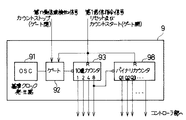
図3に第2のカウンタ9の構成を示す。91は1MHzの基準クロックを発振するクロック発生器、92はクロック発生器91からの基準クロックを通過させたり止めたりするゲートで前記第1送信指令信号を受けるとゲート92が開き基準クロックを通過させるようになり、前記第1のカウンタ8からの第n受信波検知信号を受けると、それまで開いていたゲート92が閉じるように構成されている。
【0033】
93,94,…,97は10進1桁のカウンタで、93が1桁目、94が2桁目、…、97が5桁目の10進数の計数を分担し、最下位の1桁目のカウンタ93は、ゲート92を通過してきた基準クロックを計数し、そのキャリーを2桁目のカウンタ94に入力する。このようにして、各カウンタ93,94,…のキャリーが次の上位桁のカウンタ94,…,95に入力されて、測定値T1 ,T2 を計数する。
【0034】
なお第1送信指令信号はゲート92を開くとともに、各桁のカウンタ93,94,…,97の内容を零にリセットする。
10進各桁のカウンタ93,94,…,97は、それぞれ1,2,4,8出力端子を備えていて、これらの端子からの1,2,4,8出力がコントローラ部7へ入力されるようになっている。
【0035】
なお各10進カウンタ93,94,…,97はそれぞれ100 ,101 ,…,104 の各桁を分担し、全部で10進5桁のカウンタを構成しているが、これらのカウンタの数は必要とする第2のカウンタ9の10進数の桁数に応じて用意される。
【0036】
コントローラ部7は順方向計測時と逆方向計測時において、第1のカウンタ8からの第n受信波検知信号を受ける都度第2のカウンタ9の測定値T1 ,T2 を読み取り、時間逆数差法を用いて流速、流量、積算流量等の演算を行うが、逆数の計算を行うのに前記〔発明が解決しようとする課題〕の欄で説明したような6桁程度の割算をマイクロコンピュータで計算することを避け、マイクロコンピュータのメモリに格納したデータテーブルを活用して時間逆数値を短時間で導くようにしている。
【0037】
図1の実施の形態では、第2のカウンタ9から読み取るべき測定値T1 ,T2,…これは1MHzの基準クロックを10進カウンタで時間T1 ,T2 の間カウントした計数値であらわされる…より遅れ時間に相当する一定値nτを1MHzの基準クロックの計数値に換算した値を減じた値T1 −nτ,T2 −nτを最下位1桁とその他の上位桁に分けて、最下位1桁の数値をb、その他の上位桁の数値をaとして、該その他の上位桁の数値aに相当するアドレスと該アドレスに対応するデータ1/(10a)の集合からなる〔表1〕のデータテーブルをマイクロコンピュータのメモリに格納しておく。
【0038】
1MHzの基準クロックの計数値で表現される第2のカウンタ9の測定値T1,T2 や遅れ時間nτは、距離L、流体の流れの速さV、順方向及び逆方向における各繰り返し回数n、超音波の周期、流体の流れと超音波の発射方向とでなす角度等で決まるが、T1 −nτ,T2 −nτの数値が取り得る範囲が1MHzの基準クロックの計数値で表現して例えば15001から45000までの範囲であるとすると、これらの計数値は45000−15000=30000個の計数値の集合からなるデータテーブルを設けることになる。
【0039】
図1の実施形態では、もっと少ない個数の集合からなるデータテーブルを用意して、このデータテーブルから時間逆数値を読み出すことで前記6桁程度の割算をしなくても良く、かつ小さなデータテーブルですむようにしている。
【0040】
即ち、15001,15002,…,44999,45000からなる30000個の計数値の集合を構成する各計数値、つまり第2のカウンタ9から読み取るべき測定値T1 −nτ,T2 −nτを最下位1桁とその他の上位桁に分けて、最下位1桁の数値をb、その他の上位桁の数値をaとして、該その他の上位桁の数値aに相当するアドレスと該アドレスの逆数に対応するデータ1/(10a)の集合からなるデータテーブルをマイクロコンピュータのメモリに格納しておく。
【0041】
このデータテーブルは、測定値T1 −nτが15001のときは、最下位1桁の数値bは1となる。そして、その他の上位桁の数値は1500である。従って、この測定値15001に対応するアドレスは1500、該アドレス1500に対応するデータ1/(10a)は、
1/(10×1500)=6.6666667×10-5・・・(4)
となる。なお上式の右辺の8桁の有効数字の最下位桁の6はその下位の桁の6を四捨五入して7と表現したものである。
【0042】
このようにして、アドレスと対応するデータのデータテーブルは〔表1〕のようになる。なお表1のデータは、上記(4)式の右辺の8桁の有効数字と同様の数値の小数点を外してあらわしたものである。
【0043】
【表1】

このようにして〔表1〕のデータテーブルを作成してマイクロコンピュータのメモリに格納するとデータの数は前記30000個の1/10の3000個になる。
【0045】
第2のカウンタ9の測定値T1 −nτ,T2 −nτの最下位桁が0の値の上位桁の数値の逆数の有効数字8桁の集合で表1のデータテーブルを作成したわけである。
【0046】
こうして〔表1〕のデータテーブルでは、メモリ容量が小さくて済むが、第2のカウンタ9の測定値T1 −nτ,T2 −nτの最下位桁が0以外の数値のときの値を直接テーブルから読み出すことができない。
【0047】
例えば第2のカウンタ9の測定値T1 又はT2 が17943の場合、この測定値17943に対応するアドレスは一定値nτを600とすると17943−600=17343となる。これに対応する逆数のデータをずばり〔表1〕のデータテーブルからは読み出せない。そこで測定値17343に対応する時間逆数値を〔表1〕のデータテーブルから読み出したデータを活用して直線近似で求める。
【0048】
第2のカウンタ9の測定値が17943であるので、この測定値の数値から一定値nτ=600を引いた前述のように17343である。そこで、その上位の4桁の数値1734に相当するアドレスと、この上位桁の数値1734に1を加算した1735に相当するアドレスより、1/(10×1734)と1/(10×1735)に相当する二つの格納データを〔表1〕のデータテーブルから読み出す。実際にはコントローラ部7を構成するマイクロコンピュータのメモリに格納したデータから読み出す。
【0049】
アドレス データ
1734 57670127
1735 57636888
そして、これらの二つのデータから測定値17943に対応するデータを次の(5)式で直線近似を使って導く。
【0050】
測定値17943に対応するデータ=57670127−(57670127
−57636888)×(3/10) ・・・(5)
(5)式の演算をマイクロコンピュータでする場合、(57670127−57636888)×(3/10)の計算に多少の時間がかかるものの、テーブルが小さくなり、実現可能となる。
このようにして、小さいテーブルから読み出したデータを用いて、直線近似でテーブルの中間のデータを演算することで、テーブルを格納するメモリが小さくてすみ、しかも全体として割算に長時間をかけなくてすむ。
【0051】
(5)式の演算以後の流速、流量、積算流量等の演算は周知の方法でできるので詳細な説明を省略する。
なお、データテーブルのデータは、〔表1〕の値から一定値を減じた値として記憶格納するようにしてもよい。この場合のオフセット分は、その後の演算{1/(T1 −nτ)}−{1/(T2 −nτ)}で差し引かれて相殺されるので問題にはならない。また流量等の演算を考慮して、データを流管の断面積等の定数を乗じた値として記憶格納することで、後の演算時間を小さくすることができる。
【0052】
上記第1の実施の形態では、発明の考え方の基本を説明するための第1の実施態様を述べたが、次の第2の実施態様のように流量計を構成してもコントローラでの演算時間を小さくできる。
【0053】
図1のブロック図で、コントローラ部7を構成するマイクロコンピュータの作用だけが前記第1の実施態様と相違するので、以下、この相違点を主体にして第2の実施態様を説明する。
【0054】
第2のカウンタ9から読み取るべき測定値T1 又はT2 を最下位1桁の数値Bとその他の上位桁の数値Aに分けて、該その他の上位桁の数値Aに相当するアドレスと、該アドレスに対応する前記第2のカウンタ9から読み取った測定値T1又はT2 より遅れ時間に相当する一定値nτを減じた時間T1 −nτ又はT2 −nτの逆数1/(T1 −nτ)又は1/(T2 −nτ)に対応するデータ1/(10A−nτ)との集合からなるデータテーブル(表2)をマイクロコンピュータのメモリに格納し、
順方向又は逆方向の計測に当たって第2のカウンタ9から読み取った測定値T1 又はT2 に対応する前記上位桁の数値Aに相当するアドレスと、この上位桁Aに1を加算した数値A+1に相当するアドレスより両アドレスに対応する二つの時間逆数の数値1/(10A−nτ)と1/(10(A+1)−nτ)に相当する二つの格納データを前記データテーブル(表2)から読み出し、これらのデータと前記測定値T1 又はT2 の最下位1桁の数値Bとから時間逆数1/(T1 −nτ)又は1/(T2 −nτ)に相当する値1/(10A+B−nτ)を直線近似によって導き、流速や流量の演算に使用する。
【0055】
前記第1の実施態様では、第2のカウンタ9から読み取るべき測定値T1 ,T2 から遅れ時間に相当する一定値nτを減じた値、T1 −nτ,T2 −nτがとり得る範囲が15001から45000の場合について、最下位の桁を除くその他の上位桁の数値1500〜4500をアドレスとして、各アドレスに対応するデータ1/(10×1500)〜1/(10×4500)を〔表1〕のようなデータテーブルとしてメモリに格納した。
【0056】
従って、メモリに格納した〔表1〕のデータテーブルのアドレスにアクセスするには、第2のカウンタ9から読み取った測定値T1 ,T2 から遅れ時間に相当する一定値nτを減算してT1 −nτやT2 −nτを得てから、その最下位の桁を除いたその他の上位桁の数値をアドレスとしてアクセスしていた。
【0057】
ところが、第2の実施態様では、前記〔表1〕に対応する数値を使って〔表2〕のデータテーブルを作成すると、次のようになる。
基準クロック等の条件が前記第1の実施態様と同じで、一定値nτが600カウントとすると、第2のカウンタ9から読み取るべき測定値T1 ,T2 の範囲は15001+600〜45000+600、つまり15601〜45600となる。
【0058】
この15601〜45600という測定値が第2のカウンタ9の測定値として直接コントローラ部7のマイクロコンピュータで読み取られる。この測定値は1MHzの基準クロックのカウント値である。
【0059】
測定値15601に対応するアドレスは最下位桁の1を除いた1560となり、該アドレス1560に対応するデータ1/(10A−nτ)は、A=1560、nτ=600であるから、
アドレス1560に対応するデータ=1/(15600−600)
=1/15000=6.6666667×10-5 ・・・(6)
となる。
【0060】
この(6)式の右辺のデータは前記第1の実施態様で説明した(4)式のデータと全く同じである。
そこで、〔表2〕のデータテーブルを次のように作成して、コントローラ部7のマイクロコンピュータに記憶格納する。
【0061】
【表2】
この第2の実施態様の場合も、データの数は前記第1の実施態様のときと同じ3000個という小さな数であり、かつ各データの数値は〔表1〕の場合のデータの数値と同じである。
【0063】
ところで、この第2の実施態様で、第2のカウンタ9で測定した見掛け上の伝搬時間の総和T1 又はT2 が前記第1の実施態様の場合に使用した測定値17943であったとする。
【0064】
この場合のアドレスは17943の最下位の1桁の数値3を除いた他の上位桁の数値であるから、B=3,A=1794となる。従ってアドレスAは1794となり、このときの時間逆数は〔表2〕のデータテーブルからのデータとして、57670127を読み出すことができる。
【0065】
またA+1のアドレスは1794+1=1795となり、このアドレス1795に対応する時間逆数は〔表2〕のデータテーブルからのデータとして57636888を読み出すことができる。
【0066】
従って、第2のカウンタ9の測定値17943に対する時間逆数のデータは、上記二つのデータから直線近似で次のように求めることができる。
測定値17943に対応するデータ=57670127−
(57670127−57636888)×(3/10)・・・(7)
上記(7)式は、前記第1の実施態様の場合の(5)式と同じであり、流速、流量、積算流量等を求めるその後の演算は、当然第1の実施態様と同様にして行うことができる。
【0067】
この第2実施態様は、前記第1の実施態様と比較して、データテーブルにアクセスしてデータを読み出すときに、第2のカウンタ9の測定値から一定の遅れ時間に相当する値nτ=600カウントを減算した値からアドレスを決める必要がないので、順方向や逆方向の測定の都度、nτ=600カウントの値を測定値T1 又はT2 から引き算する操作が不要となり、その分演算速度や消費電流の面でより有利となる。
【0068】
この第2の実施態様の場合でも、データテーブルのデータは、〔表2〕の値から一定値を減じた値として記憶格納するようにしてもよい。また流量等の演算を考慮して、データを流管の断面積等の定数を乗じた値として記憶格納することで後の演算時間を小さくすることができる。
【0069】
【実施例】
次に請求項1の発明に対応する実施例について説明する。この実施例では、図1のブロック図に示す第2のカウンタ9の構成が図4のように変わっており、かつコントローラ部7を構成するマイクロコンピュータの作用が前記実施態様と相違するので、以下この相違点を主体にして説明する。
【0070】
図4において、9は第2のカウンタで、91は第2の実施態様の基準カウンタ91と同じ1MHzの基準クロックを発振する基準クロック発生器、92は第2の実施態様のゲート92と同じように基準クロック発生器91からの1MHzの基準クロックを第1送信指令信号と第n受信波検知信号に応じて開閉するゲート、93は第2の実施態様の10進1桁のカウンタ93と同様に、ゲート92が開いている間の1MHzの基準クロックを計数する1桁の10進カウンタで構成され、10進カウンタ93より上位が2進カウンタ98で構成されて図示のように接続されている。
【0071】
10進カウンタ93と2進カウンタ98は第1送信指令信号が各リセット端子Rに入力されるとその内容が零にリセットされる。また10進カウンタ93の1,2,4,8出力と2進カウンタ98の出力Q1 ,Q2 ,Q3 ,…はコントローラ部7へ接続されている。
【0072】
この実施例ではコントローラ部7を構成するマイクロコンピュータが第2のカウンタ(9)の測定値(T1 又はT2 )として読み取るべき数値を、その上位桁を2進数(a′)で、最下位桁を10進数(b)で読み取り、別途、前記2進数の上位桁(a′)を10進変換した値(c)の逆数に1/10を乗じたデータ1/(10c)を上位桁(a′)をアドレスとするデータテーブル〔表3〕として前記マイクロコンピュータのメモリに格納し、
上位桁(a′)に相当するアドレスと、これに1を加算した数値(a′+1)に相当するアドレスより両アドレスに対応する時間逆数の数値1/(10c)と1/{10(c+1)}に相当する二つのデータを読み出し、これらのデータと前記下位桁の数値(b)とから直線近似によって時間逆数{1/(T1 −nτ)又は1/(T2 −nτ)}に相当する値1/(10c+b)を導き、以後の流速又は流量等の演算に使用するようにしている。
【0073】
この実施例では、マイクロコンピュータのデータテーブルのアドレスは2進数である。
前述の実施態様の数値例のように、アドレス1734から、対応するデータ57670127を得る場合、実際には10進数1734を16進化2進表現であらわした2進数に変換して6C6Hとし、これを加工して得たデータの格納アドレスを求めることを行っている。
【0074】
マイクロコンピュータを8ビットのマイクロコンピュータとすると、4個のアドレス分のエリアがメモリに割り当てられていて、下記〔表3〕のデータテーブルを記憶格納しておく。
【0075】
※を付けた行のアドレスを出すには6C6を4倍して、更にオフセット分の一定値αを加算して、この計算で格納アドレスを出す。
【0076】
【表3】
この実施例ではマイクロコンピュータの負担を小さくするため第2のカウンタ9における最下位の10進1桁のカウンタ93より上位の桁には2進カウンタ(バイナリカウンタ)98を使い、10進から2進への煩わしい変換を不要としている。
【0078】
なお、遅れ時間nτに相当する一定値の引き算は、10進数と2進数が混在した数値でも全10進数や全2進数の時と同様に可能である。
また、この実施例の場合でも、データテーブルのデータは、[表3]の値から一定値を減じた値として記憶格納するようにしてもよい。また流量等の演算を考慮して、データを流管の断面積等の定数を乗じた値として記憶格納することで後の演算時間を小さくすることができる。
【0079】
【発明の効果】
本発明の超音波流量計は、上述のように構成されているので、従来技術で行っていた有効数字が6桁程度の割算を順方向や逆方向の測定値T1 ,T2 から行うことが不必要となり、予めメモリに記憶格納してあるデータテーブルのアドレスをアクセスして時間逆数値に相当するデータを読み出して、流速、流量や積算流量の演算に活用できる。
【0080】
その結果、高速動作のマイクロコンピュータが不要で、演算時間が短くて済むため、低消費電流でかつ低電圧で作動する超音波流量計が実用化できるという効果を奏する。
【0081】
また、データテーブルの大きさが小さくて済みメモリ容量が小さくても良く、この点においても効果的である。
【図面の簡単な説明】
【図1】 本発明の好ましい実施形態のブロック図である。
【図2】 図1の実施形態のタイムチャートである。
【図3】 本発明の実施形態に用いる第2のカウンタの電気回路図である。
【図4】 本発明の実施例に用いる第2のカウンタの電気回路図である。
【図5】 超音波流量計の原理を説明する略図である。
【図6】 従来技術の受信波検知部の動作を説明するための電気信号波形を示す線図である。
【符号の説明】
1 流管
2 上流側の送受波器
3 下流側の送受波器
4 受信波検知部
5 切替部を構成する信号切替器
6 送波器駆動部
7 コントローラ部
8 第1のカウンタ
9 第2のカウンタ
10 切替部を構成する切替スイッチ
91 基準クロック発生器
92 ゲート
93 最下位の1桁の10進カウンタ
94 101 位の1桁の10進カウンタ
97 104 位の1桁の10進カウンタ
98 2進カウンタ
a 数値bの桁以外の上位桁の数値
b 最下位1桁の数値
a 2進数の上位桁の数値a′を10進数に変換した数値
a′ 2進数の上位桁の数値
A 数値Bの桁以外の上位桁の数値
B 最下位1桁の数値
T1 順方向計測時の測定値、時間
T2 逆方向計測時の測定値、時間
n 順方向又は逆方向計測時の繰り返し回数
nτ 遅れ時間[0001]
BACKGROUND OF THE INVENTION
The present invention relates to an improvement in an ultrasonic flow meter.
[0002]
[Prior art]
An ultrasonic flowmeter using the time reciprocal difference method is known.
In FIG. 5, assuming that the sound velocity in the static fluid is C and the fluid flow velocity is V, if the propagation direction of the sound wave coincides with the direction along the flow (hereinafter referred to as the forward direction), the propagation velocity is (C + V In the case of the direction against the flow (hereinafter referred to as the reverse direction), (CV).
[0003]
When a pair of
t1= L / (C + V) (1)
t2= L / (C-V) (2)
It becomes.
[0004]
The above propagation time t of ultrasonic waves in the forward and reverse directions1, T2The flow velocity V was calculated from this, and the flow rate was further obtained or the integrated flow rate was obtained.
The flow velocity V is independent of the speed of sound C from the above equations (1) and (2).
V = (L / 2) [(1 / t1)-(1 / t2]] ... (3)
As time and t1, T2Reciprocal of 1 / t1, 1 / t2This is called the time reciprocal difference method.
[0005]
Drive pulse P to transmitter 2 (or 3)1When excitation is applied, propagation time t1(Or t2) Later, the ultrasonic wave reaches the receiver 3 (or 2), but the received wave (electrical signal) received by the receiver 3 (or 2) gradually grows from zero at the top value as shown in FIG. However, the first wave, the second wave, the third wave, the fourth wave, and the fifth wave become large values in order, and the waveform gradually attenuates after the peak value is passed.
[0006]
Propagation time t1(Or t2) Is the beginning of the waveform indicated by the symbol “A”, but since this point cannot be detected, the zero cross point after the third or fifth wave is actually set to the receiver 3 ( Or it is detected by the received wave detector connected to 2). In FIG. 6, the drive pulse P1To the zero cross point “b” immediately after the third wave of the received wave is detected by the received wave detecting unit, and the propagation time t is subtracted from the delay time τ previously obtained and stored in another experiment.1(Or t2)
[0007]
In order to increase the resolution of the propagation time and improve the measurement accuracy of the flow meter, the next transmission in the same direction is performed simultaneously with reception instead of the transmission / reception of one ultrasonic wave, and transmission / reception in the same direction multiple times (n times) Continuously and repeatedly, the time from the first (first) transmission to the last nth reception is measured, and the time t from the first transmission to reception is determined from that value.1(Or t2).
[0008]
First transmission or drive pulse P16 to the n-th reception, since the reception wave detection unit directly detects the arrival of the ultrasonic wave is the zero cross point “b” in FIG. 6 as described above, the measurement is being performed n times in the same direction. If the flow velocity V is constant, nt in the forward direction1+ Nτ, nt in the reverse direction2+ Nτ.
[0009]
Therefore, the time nt from the first transmission to the nth reception1+ Nτ and nt2The flow rate and the flow rate were obtained by using the time reciprocal difference method using + nτ, and the integrated flow rate (volume) was further obtained.
[0010]
The time from the first transmission to the nth reception in the forward measurement is T1, The time from the first transmission to the nth reception in the reverse measurement is T2Then, as an expression corresponding to the expressions (1) and (2),
T1-Nτ = nL / (C + V) (1A)
T2−nτ = nL / (C−V) (2A)
Is obtained.
[0011]
The flow velocity V is independent of the sound velocity C from the above equations (1A) and (2A).
V = (nL / 2) [{1 / (T1-Nτ)}-{1 / (T2−nτ)}] (3A)
As required.
[0012]
In this type of ultrasonic flowmeter, the switching control between the forward direction measurement and the reverse direction measurement is performed by a controller unit configured by a microcomputer, and the calculation of the mathematical expression (3A) is also performed using this microcomputer. ing.
[0013]
[Problems to be solved by the invention]
In the prior art, 1 / (T1-Nτ) or 1 / (T2-Nτ) is divided by a microcomputer.
[0014]
In general, microcomputers take time to divide, and this type of flowmeter requires a lot of time for calculation, so it takes much more time and requires a high-speed microcomputer, which is expensive and requires high power. There was a problem.
[0015]
For example, the speed of sound is 440 m / sec, the distance L is 0.2 m, the number of repetitions n is 200 times, the time T1Or
T-nτ = 200 × 0.2 × 106/ 440 count
= 90909 count = 90909 × 10-6s
It becomes.
[0016]
Therefore, it is necessary to divide the effective number of 1 ÷ 90909 by about 6 digits according to the equation (3A).
Actually, it depends on the difference in fluid flow velocity V and the forward or reverse measurement.1, T2Becomes a different value, or delay time nτ is time T1, T2The subtraction is the denominator of the division. When the ultrasonic frequency is 500 KHz, nτ is the reference clock of 1 MHz when the zero cross point “b” of the third wave of the received wave is detected as shown in FIG. The count value of
200 x 1.5 x 2 = 600 counts
Therefore, it is about 0.66% of the 90909 count, and the number of digits for division is about 6 digits.
[0017]
In order to perform normal division with a microcomputer, calculation is performed while performing subtraction many times, and the number of subtractions is determined by actually subtracting. Therefore, if division with a large number of digits is performed, the calculation may not end at the flow rate or flow rate measurement interval.
[0018]
Even if the flow meter system is designed to be in time, there is a problem in that the microcomputer keeps moving and low power consumption cannot be realized.
Accordingly, an object of the present invention is to provide an ultrasonic flowmeter using the time reciprocal difference method that can eliminate such problems.
[0019]
[Means for Solving the Problems]
To achieve the above purpose,Claim1The invention of
A pair of ultrasonic transducers (2) and (3) acting both on the transmitting side and on the receiving side for transmitting and receiving ultrasonic waves in the same or oblique direction as the flow in the fluid flow;
A reception wave detector (4) that outputs a reception wave detection signal when a reception wave transmitter (3 or 2) is connected and a reception wave is detected;
When the first transmission command signal is input, the transmitter / receiver (2 or 3) is driven, and thereafter an n-th received wave detection signal to be described later is received for each received wave detection signal from the received wave detector (4). A transmitter driver (6) for driving the transmitter / receiver (2 or 3) on the transmitting side until input,
When measuring in the forward direction, connect the upstream transducer (2) to the transducer driver (6) and connect the downstream transducer (3) to the received wave detector (4). When measuring in the reverse direction, the downstream transducer (3) is connected to the transducer driver (6) and the upstream transducer (2) is connected to the received wave detector (4). A switching unit (5, 10) to perform,
The first transmission command signal is output each time while the switching unit (5, 10) is alternately switched at a fixed timing to output a transmission / reception switching signal for switching between the forward measurement and the reverse measurement to alternately switch transmission / reception. A controller unit (7) for outputting
The received wave detection signal is received from the received wave detection unit (4), and the nth received wave detection signal is detected and output at the nth received wave detection signal every time the forward measurement and the reverse measurement are performed. 1 counter (8),
Time from the first transmission command signal to the nth received wave detection signal at the time of forward measurement (T1) And the time from the first transmission command signal to the n-th received wave detection signal (T2A second counter (9) for measuring)
When the nth received wave detection signal is received, the measured value (T1Or T2), And an ultrasonic flowmeter that performs calculations such as a flow rate and a flow rate using the inverse time difference method in the controller unit (7),
The time measuring unit constituting the second counter (9) is a counter that counts the reference clock, the lowest order is a decimal counter (93) with one digit, and the higher order is a binary counter (98),
The controller unit (7) is composed of a micro computer,
The microcomputer measures the value (T) of the second counter (9).1Or T2) Is read as a binary number (a ′) and the least significant digit as a decimal number (b).
Separately,
From the address corresponding to the upper digit (a ′) and the address corresponding to the numerical value (a ′ + 1) obtained by adding 1 to this, the
[0020]
Claim2The present invention comprises a pair of ultrasonic transducers (2) and (3) that act both on the transmitting side and on the receiving side for transmitting and receiving ultrasonic waves in the same or oblique direction as the flow in the fluid flow,
A reception wave detector (4) that outputs a reception wave detection signal when a reception wave transmitter (3 or 2) is connected and a reception wave is detected;
When the first transmission command signal is input, the transmitter / receiver (2 or 3) is driven, and thereafter an n-th received wave detection signal to be described later is received for each received wave detection signal from the received wave detector (4). A transmitter driver (6) for driving the transmitter / receiver (2 or 3) on the transmitting side until input,
When measuring in the forward direction, connect the upstream transducer (2) to the transducer driver (6) and connect the downstream transducer (3) to the received wave detector (4). When measuring in the reverse direction, the downstream transducer (3) is connected to the transducer driver (6) and the upstream transducer (2) is connected to the received wave detector (4). A switching unit (5, 10) to perform,
The first transmission command signal is output each time while the switching unit (5, 10) is alternately switched at a fixed timing to output a transmission / reception switching signal for switching between the forward measurement and the reverse measurement to alternately switch transmission / reception. A controller unit (7) for outputting
The received wave detection unit (4) receives the received wave detection signal, detects the nth received wave detection signal and outputs the nth received wave detection signal for each measurement in the forward direction and in the reverse direction. 1 counter (8),
Time from the first transmission command signal to the nth received wave detection signal at the time of forward measurement (T1) And the time from the first transmission command signal to the n-th received wave detection signal (T2A second counter (9) for measuring)
When the nth received wave detection signal is received, the measured value (T1Or T2), And an ultrasonic flowmeter that performs calculations such as a flow rate and a flow rate using the inverse time difference method in the controller unit (7),
The time measuring unit constituting the second counter (9) is a counter that counts the reference clock, the lowest order is a decimal counter (93) with one digit, and the higher order is a binary counter (98),
The controller unit (7) is composed of a micro computer,
The microcomputer measures the value (T) of the second counter (9).1Or T2) Is read as a binary number (a ′) and the least significant digit as a decimal number (b).
Separately, the reciprocal data of the value (c) obtained by decimal conversion of the upper digit (a ′) of the binary number is stored in the memory of the microcomputer as a data table having the upper digit (a ′) as an address,
Two data of the reciprocal time corresponding to both addresses are read out from the address corresponding to the upper digit (a ′) and the address corresponding to the numerical value obtained by adding 1 to these, and these data and the numerical value (b) of the lower digit To the inverse of time {1 / (T1-Nτ) or 1 / (T2-Nτ)}, and is used for subsequent calculation of flow velocity or flow rate.
Claim3The invention of claim2In the ultrasonic flowmeter, the data stored in the data table is claimed in claim2The data table is configured by using as a data a value obtained by subtracting a constant value from the data described in the above or a value obtained by multiplying the constant value.
[0021]
DETAILED DESCRIPTION OF THE INVENTION
FIG. 1 illustrates the present invention.First to explain the basics of thinkingFIG. 2 is a time chart in the embodiment. In the figure,
[0022]
Reference numeral 4 denotes a received wave detection unit, which is connected to the input of the receiving side transmitter /
[0023]
In FIG. 2, the first, second, third,..., And nth received wave detection signals are respectively labeled 1, 2, 3,.
6 excites the transmitter /
[0024]
Reference numeral 7 denotes a controller unit composed of a microcomputer that outputs a transmission / reception switching signal for alternately switching between forward measurement and reverse measurement by switching the signal switch 5 and the
[0025]
The signal selector 5 and the
[0026]
When measuring in the reverse direction, the
[0027]
8 is a first counter that receives a received wave detection signal from the received wave detection unit 4 and counts the received wave detection signal for each measurement in the forward direction and in the reverse direction, and the count value becomes n. That is, the nth received wave detection signal is detected and the nth received wave detection signal is output. Note that the count value of the
[0028]
A second counter 9 is a time T from the first transmission command signal P from the controller unit 7 to the nth received wave detection signal from the
[0029]
As shown in FIG. 2, the apparent propagation time of each time in the forward direction is the net propagation time t.1T added to each time delay time τ1+ Τ, the time from the first transmission command signal P to the n-th received wave detection signal, that is, the measured value T of the second counter 9 at the time of forward measurement1Is
T1= Nt1+ Nτ
It is expressed.
[0030]
Similarly, the measured value T of the second counter 9 at the time of backward measurement2Is
T2= Nt2+ Nτ
It is expressed.
[0031]
The time measuring unit constituting the second counter 9 is composed of a decimal counter, counts a 1 MHz reference clock, and from the first transmission command signal P to the nth received wave detection signal at the time of forward measurement shown in FIG. Time T1And a time T from the first transmission command signal to the nth received wave detection signal at the time of reverse direction measurement.2Is counted as the count value of the reference clock.
[0032]
FIG. 3 shows the configuration of the second counter 9. 91 is a clock generator that oscillates a 1 MHz reference clock, and 92 is a gate that passes or stops the reference clock from the
[0033]
93, 94,..., 97 are decimal one digit counters, 93 is the first digit, 94 is the second digit,.
[0034]
The first transmission command signal opens the
Each of the decimal counters 93, 94,..., 97 has 1, 2, 4, 8 output terminals, and 1, 2, 4, 8 outputs from these terminals are input to the controller unit 7. It has become so.
[0035]
Each of the decimal counters 93, 94,.0, 101, ..., 10FourThe counters of 5 decimal digits are configured in total, and the number of these counters is prepared according to the number of decimal digits of the second counter 9 required.
[0036]
The controller unit 7 measures the measured value T of the second counter 9 each time it receives the nth received wave detection signal from the
[0037]
In the embodiment of FIG. 1, the measured value T to be read from the second counter 91, T2, ... This is the time T with a decimal counter of 1MHz reference clock1, T2Is expressed as a count value counted during the period ... A value T obtained by subtracting a value obtained by converting a constant value nτ corresponding to a delay time into a count value of a reference clock of 1 MHz.1-Nτ, T2-Nτ is divided into the lowest 1 digit and other upper digits, the lowest 1 digit numerical value is b, the other higher digit numerical value is a, and the address corresponding to the other higher digit numerical value a and the address A data table of [Table 1] consisting of a set of
[0038]
The measurement value T of the second counter 9 expressed by the count value of the reference clock of 1 MHz.1, T2The delay time nτ is determined by the distance L, the fluid flow speed V, the number of repetitions n in the forward and reverse directions, the cycle of the ultrasonic wave, the angle formed by the fluid flow and the ultrasonic wave emission direction, and the like. , T1-Nτ, T2If the range that can be taken by the value of −nτ is expressed by a count value of a reference clock of 1 MHz, for example, a range from 15001 to 45000, these count values are composed of a set of 45000-15000 = 30000 count values. A data table will be provided.
[0039]
In the embodiment of FIG. 1, it is not necessary to divide by about 6 digits by preparing a data table consisting of a smaller number of sets and reading the reciprocal time value from this data table, and a small data table. I am trying to do it.
[0040]
That is, each count value constituting a set of 30000 count values consisting of 15001, 15002,..., 44999, 45000, that is, a measurement value T to be read from the second counter 9.1-Nτ, T2-Nτ is divided into the lowest 1 digit and other upper digits, the lowest 1 digit numerical value is b, the other higher digit numerical value is a, and the address corresponding to the other higher digit numerical value a and the address A data table consisting of a set of
[0041]
This data table contains measured values T1When −nτ is 15001, the lowest-order numerical value b is 1. The numerical value of the other upper digits is 1500. Therefore, the address corresponding to the measured value 15001 is 1500, and the
1 / (10 × 1500) = 6.6666667 × 10-Five... (4)
It becomes. The least significant digit 6 of the eight significant digits on the right side of the above expression is expressed by rounding the least significant digit 6 to 7.
[0042]
In this way, the data table of the data corresponding to the address is as shown in [Table 1]. Note that the data in Table 1 is obtained by removing the decimal point of the same numerical value as the 8-digit significant number on the right side of the above equation (4).
[0043]
[Table 1]
When the data table of [Table 1] is created in this way and stored in the memory of the microcomputer, the number of data becomes 3000, which is 1/10 of the above 30000.
[0045]
Measurement value T of second counter 91-Nτ, T2The data table of Table 1 was created with a set of 8 significant digits that are the reciprocal of the numerical value of the upper digit of the value with the lowest digit of -nτ being 0.
[0046]
Thus, in the data table of [Table 1], the memory capacity may be small, but the measured value T of the second counter 91-Nτ, T2The value when the least significant digit of −nτ is a numerical value other than 0 cannot be directly read from the table.
[0047]
For example, the measured value T of the second counter 91Or T217943, the address corresponding to the measured value 17943 is 17943-600 = 17343 when the constant value nτ is 600. The reciprocal data corresponding to this cannot be read from the data table of [Table 1]. Therefore, an inverse time value corresponding to the measured value 17343 is obtained by linear approximation using data read from the data table of [Table 1].
[0048]
Since the measured value of the second counter 9 is 17943, it is 17343 as described above, which is obtained by subtracting the constant value nτ = 600 from the numerical value of this measured value. Therefore, the address corresponding to the upper four-digit value 1734 and the address corresponding to 1735 obtained by adding 1 to the upper-digit value 1734 are 1 / (10 × 1734) and 1 / (10 × 1735). Two corresponding stored data are read from the data table of [Table 1]. Actually, the data is read from the data stored in the memory of the microcomputer constituting the controller unit 7.
[0049]
Address data
1734 5770127
1735 576368888
Then, from these two data, data corresponding to the measured value 17943 is derived using linear approximation in the following equation (5).
[0050]
Data corresponding to measured value 17943 = 5770127- (5767127
-57636888) × (3/10) (5)
When the calculation of equation (5) is performed by a microcomputer, the calculation of (5760127127-5766888) × (3/10) takes some time, but the table becomes small and can be realized.
In this way, by using the data read from the small table and calculating the intermediate data of the table by linear approximation, the memory for storing the table can be reduced, and the division as a whole does not take a long time. Tesumu.
[0051]
Since the calculation of the flow velocity, the flow rate, the integrated flow rate, etc. after the calculation of the equation (5) can be performed by a well-known method, the detailed description is omitted.
The data in the data table may be stored and stored as a value obtained by subtracting a certain value from the value in [Table 1]. In this case, the offset is calculated by a subsequent calculation {1 / (T1-Nτ)}-{1 / (T2−nτ)} is subtracted and canceled out, so there is no problem. In addition, taking into account calculations such as flow rate, data can be stored and stored as a value multiplied by a constant such as the cross-sectional area of the flow tube, thereby reducing the subsequent calculation time.The
[0052]
UpFirstImplementation formIn stateOf the inventionFirst to explain the basics of thinkingDescribe the embodimentSolidBut,Next second embodimentEven if the flow meter is configured likeThe computation time in the controller can be reduced.The
[0053]
FigureIn the block diagram of FIG. 1, only the operation of the microcomputer constituting the controller unit 7 isFirstSince it is different from the embodiment, the following will focus on this difference.Second embodimentWill be explained.
[0054]
FirstMeasured value T to be read from the counter 9 of 21Or T2Is divided into the lowest one digit B and the other higher digit A, the address corresponding to the other higher digit A, and the measured value read from the second counter 9 corresponding to the address. T1Or T2A time T obtained by subtracting a constant value nτ corresponding to the delay time.1-Nτ or T2Reciprocal of -
The measured value T read from the second counter 9 in the forward or reverse measurement1Or T2And an address corresponding to the numerical value A of the upper digit corresponding to 1 and a
[0055]
SaidFirstIn an embodiment, the measured value T to be read from the second counter 9.1, T2A value obtained by subtracting a constant value nτ corresponding to the delay time from T1-Nτ, T2When the range that −nτ can take is 15001 to 45000,
[0056]
Therefore, to access the address of the data table of [Table 1] stored in the memory, the measured value T read from the second counter 9 is used.1, T2A constant value nτ corresponding to the delay time is subtracted from T1-Nτ and T2After obtaining -nτ, the numerical value of the other upper digits except the lowest digit was accessed as an address.
[0057]
However, the secondEmbodiment ofThen, when the data table of [Table 2] is created using the numerical values corresponding to [Table 1], it becomes as follows.
The conditions such as the reference clockFirstAs in the embodiment, when the constant value nτ is 600 counts, the measured value T to be read from the second counter 9 is as follows.1, T2The range is 15001 + 600-45000 + 600, that is, 15601-45600.
[0058]
The measurement values 15601 to 45600 are directly read by the microcomputer of the controller unit 7 as the measurement values of the second counter 9. This measured value is a count value of a reference clock of 1 MHz.
[0059]
Since the address corresponding to the measurement value 15601 is 1560 excluding the least
Data corresponding to address 1560 = 1 / (15600-600)
= 1/15000 = 6.6666667 × 10-Five ... (6)
It becomes.
[0060]
The data on the right side of the equation (6)FirstThis is exactly the same as the data of equation (4) described in the embodiment.
Therefore, the data table of [Table 2] is created as follows and stored in the microcomputer of the controller unit 7.
[0061]
[Table 2]
This secondEmbodiment ofIn the case ofFirstThe number is as small as 3000 as in the embodiment, and the numerical value of each data is the same as the numerical value of data in the case of [Table 1].
[0063]
By the way, this second implementationAspectThe total apparent propagation time T measured by the second counter 91Or T2SaidFirstIt is assumed that the measurement value used in the embodiment is 17943.
[0064]
In this case, since the address is a numerical value of the other high-order digits excluding the lowest-order
[0065]
Further, the address of A + 1 is 1794 + 1 = 1799, and the time reciprocal corresponding to this address 1795 can read 5766688 as data from the data table of [Table 2].
[0066]
Therefore, the data of the reciprocal time with respect to the measured value 17943 of the second counter 9 can be obtained from the above two data by linear approximation as follows.
Data corresponding to measured value 17943 = 5770127−
(5770127-57636888) × (3/10) (7)
The above equation (7)FirstIt is the same as the equation (5) in the case of the embodiment, and the subsequent calculation for obtaining the flow velocity, flow rate, integrated flow rate, etc. is naturallyFirstIt can be performed in the same manner as in the embodiment.
[0067]
This second implementationAspectIsThe firstCompared with the embodiment, when reading data by accessing the data table, it is necessary to determine the address from the value obtained by subtracting the value nτ = 600 counts corresponding to a certain delay time from the measured value of the second counter 9. Therefore, every time measurement in the forward or reverse direction, the value of nτ = 600 counts is taken as the measured value T1Or T2This eliminates the need for subtracting from, making it more advantageous in terms of calculation speed and current consumption.The
[0068]
This secondofImplementationAspectEven in this case, the data in the data table may be stored and stored as a value obtained by subtracting a certain value from the value in [Table 2]. In consideration of calculation such as flow rate, later calculation time can be shortened by storing and storing data as a value multiplied by a constant such as the cross-sectional area of the flow tube.The
[0069]
【Example】
Next claim1Corresponding to the inventionFruitExamples will be described. In this embodiment, the configuration of the second counter 9 shown in the block diagram of FIG. 1 is changed as shown in FIG. 4 and the operation of the microcomputer constituting the controller unit 7 is different from that of the above embodiment. Based on this differenceTheoryLight up.
[0070]
In FIG. 4, 9 is the second counter and 91 is the second counter.ofImplementationAspectThe reference clock generator for oscillating the same 1 MHz reference clock as the
[0071]
When the first transmission command signal is input to each reset terminal R, the contents of the
[0072]
ThisThe fruitIn the embodiment, the microcomputer constituting the controller unit 7 measures the measured value (T of the second counter (9)).1Or T2), The upper digit (a ') of the numerical value to be read as a binary number (a'), the least significant digit as a decimal number (b), and the upper digit (a ') of the binary number converted to decimal (
From the address corresponding to the upper digit (a ′) and the address corresponding to the numerical value (a ′ + 1) obtained by adding 1 to this, the
[0073]
ThisThe fruitIn the embodiment, the address of the microcomputer data table is a binary number.
As in the numerical example of the above embodiment, when the corresponding data 5770127 is obtained from the address 1734, the decimal number 1734 is actually converted into a binary number represented by the hexadecimal representation of binary 6C6H, which is processed. The storage address of the data obtained in this way is obtained.
[0074]
If the microcomputer is an 8-bit microcomputer, four address areas are allocated to the memory, and the data table shown in Table 3 below is stored and stored.
[0075]
To obtain the address of the line marked with *, 6C6 is multiplied by 4, and a fixed value α for the offset is added, and the storage address is obtained by this calculation.
[0076]
[Table 3]
ThisThe fruitIn this embodiment, in order to reduce the burden on the microcomputer, a binary counter (binary counter) 98 is used for the digit higher than the least significant decimal one
[0078]
Note that subtraction of a constant value corresponding to the delay time nτ can be performed in the same manner as in the case of all decimal numbers and all binary numbers even in a numerical value in which decimal numbers and binary numbers are mixed.
Also thisThe fruitEven in the embodiment, the data in the data table may be stored and stored as a value obtained by subtracting a certain value from the value in [Table 3]. In consideration of calculation such as flow rate, later calculation time can be shortened by storing and storing data as a value multiplied by a constant such as the cross-sectional area of the flow tube.The
[0079]
【The invention's effect】
Since the ultrasonic flowmeter of the present invention is configured as described above, the division of a significant number of about six digits, which has been performed in the prior art, is a measurement value T in the forward direction or the reverse direction.1, T2The data table address stored in the memory in advance is accessed to read the data corresponding to the reciprocal value of the time, and can be used for the calculation of the flow rate, the flow rate and the integrated flow rate.
[0080]
As a result, there is no need for a microcomputer that operates at high speed, and the calculation time is short, so that an ultrasonic flowmeter that operates with low current consumption and low voltage can be put into practical use.
[0081]
Further, the size of the data table may be small, the memory capacity may be small, and this point is also effective.
[Brief description of the drawings]
FIG. 1 is a block diagram of a preferred embodiment of the present invention.
FIG. 2 is a time chart of the embodiment of FIG.
FIG. 3 is an electric circuit diagram of a second counter used in the embodiment of the present invention.
FIG. 4 The present inventionThe fruitIt is an electric circuit diagram of the 2nd counter used for an Example.
FIG. 5 is a schematic diagram illustrating the principle of an ultrasonic flow meter.
FIG. 6 is a diagram showing electrical signal waveforms for explaining the operation of the reception wave detection unit of the prior art.
[Explanation of symbols]
1 Flow pipe
2 Upstream transducer
3 Downstream transducer
4 Received wave detector
5 Signal switching unit that constitutes the switching unit
6 Transmitter drive
7 Controller
8 First counter
9 Second counter
10 Changeover switch constituting the changeover unit
91 Reference clock generator
92 gate
93 Decimal counter with 1 digit at the bottom
94 1011-digit decimal counter
97 10Four1-digit decimal counter
98 binary counter
a Numeric value of upper digit other than numeric digit b
b The lowest digit
a Numeric value of upper digit a 'converted to decimal number
a 'Numeric value of upper digit of binary number
A Numeric value of upper digit other than digit B
B The numerical value of the least significant digit
T1 Measurement value and time during forward measurement
T2 Measured value and time during reverse measurement
n Number of repetitions during forward or reverse measurement
nτ delay time
Claims (3)
受信側の送受波器(3又は2)が接続され、受信波を検知すると受信波検知信号を出力する受信波検知部(4)と、
第1送信指令信号を入力した時に送信側の送受波器(2又は3)を駆動し、その後は受信波検知部(4)からの受信波検知信号ごとに後述する第n受信波検知信号が入力されるまで送信側の送受波器(2又は3)を駆動する送波器駆動部(6)と、
順方向の計測を行うときは上流側の送受波器(2)を送波器駆動部(6)に接続するとともに下流側の送受波器(3)を受信波検知部(4)に接続し、逆方向の計測を行うときは下流側の送受波器(3)を送波器駆動部(6)に接続するとともに上流側の送受波器(2)を受信波検知部(4)に接続する切替部(5,10)と、
一定のタイミングで交互に切替部(5,10)を切り替えて順方向の計測と逆方向の計測を切り替える送受切替信号を出力して交互に送受の切り替えを行いながら、その都度第1送信指令信号を出力するコントローラ部(7)と、
受信波検知部(4)からの受信波検知信号を受け、順方向の計測時と逆方向の計測時毎にn番目の受信波検知信号を検知して第n受信波検知信号を出力する第1のカウンタ(8)と、
順方向計測時における第1送信指令信号から第n受信波検知信号までの時間(T1 )と、逆方向計測時における第1送信指令信号から第n受信波検知信号までの時間(T2 )を測定する第2のカウンタ(9)とを具備し、
第n受信波検知信号を受けると第2のカウンタ(9)の測定値(T1 又はT2 )を読み取り、時間逆数差法を用いて流速、流量等の演算をコントローラ部(7)で行う超音波流量計であって、
前記第2のカウンタ(9)を構成する時間計測部が基準クロックを計数するカウンタで、その最下位が1桁の10進カウンタ(93)、それより上位が2進カウンタ(98)よりなり、
前記コントローラ部(7)がマイクロコンビュータで構成され、
該マイクロコンピュータが第2のカウンタ(9)の測定値(T1 又はT2 )として読み取るべき数値を、その上位桁を2進数(a′)で、最下位桁を10進数(b)で読み取り、
別途、前記2進数の上位桁(a′)を10進変換した値(c)の逆数に1/10を乗じたデータ1/(10c)を上位桁(a′)をアドレスとするデータテーブルとして前記マイクロコンピュータのメモリに格納し、
上位桁(a′)に相当するアドレスと、これに1を加算した数値(a′+1)に相当するアドレスより両アドレスに対応する時間逆数の数値1/(10c)と1/{10(c+1)}に相当する二つのデータを読み出し、これらのデータと前記下位桁の数値(b)とから直線近似によって時間逆数{1/(T1 −nτ)又は1/(T2 −nτ)}に相当する値1/(10c+b)を導き、以後の流速又は流量等の演算に使用するようにしたことを特徴とする超音波流量計。A pair of ultrasonic transducers (2) and (3) acting both on the transmitting side and on the receiving side for transmitting and receiving ultrasonic waves in the same or oblique direction as the flow in the fluid flow;
A reception wave detector (4) that outputs a reception wave detection signal when a reception-side transducer (3 or 2) is connected and a reception wave is detected;
When the first transmission command signal is input, the transmitter / receiver (2 or 3) is driven, and thereafter an n-th received wave detection signal to be described later is received for each received wave detection signal from the received wave detector (4). A transmitter driver (6) for driving the transmitter / receiver (2 or 3) on the transmitting side until input,
When measuring in the forward direction, connect the upstream transducer (2) to the transducer driver (6) and connect the downstream transducer (3) to the received wave detector (4). When measuring in the reverse direction, the downstream transducer (3) is connected to the transducer driver (6) and the upstream transducer (2) is connected to the received wave detector (4). A switching unit (5, 10) to perform,
The first transmission command signal is output each time while the switching unit (5, 10) is alternately switched at a fixed timing to output a transmission / reception switching signal for switching between the forward measurement and the reverse measurement to alternately switch transmission / reception. A controller unit (7) for outputting
The received wave detection signal is received from the received wave detection unit (4), and the nth received wave detection signal is detected and output at the nth received wave detection signal every time the forward measurement and the reverse measurement are performed. 1 counter (8),
Time (T 1 ) from the first transmission command signal to the nth received wave detection signal at the time of forward measurement, and time (T 2 ) from the first transmission command signal to the nth received wave detection signal at the time of backward measurement. A second counter (9) for measuring
When the nth received wave detection signal is received, the measurement value (T 1 or T 2 ) of the second counter (9) is read and the flow rate, flow rate, etc. are calculated by the controller unit (7) using the time reciprocal difference method. An ultrasonic flow meter,
The time measuring unit constituting the second counter (9) is a counter for counting a reference clock, the lowest order is a decimal counter (93) having one digit, and the higher order is a binary counter (98),
The controller unit (7) is composed of a micro computer,
The microcomputer reads the numerical value to be read as the measurement value (T 1 or T 2 ) of the second counter (9), with the upper digit as binary number (a ′) and the least significant digit as decimal number (b). ,
Separately, data 1 / (10c) obtained by multiplying the reciprocal of the value (c) obtained by decimal conversion of the upper digit (a ′) of the binary number by 1/10 is used as a data table having the upper digit (a ′) as an address. Stored in the memory of the microcomputer;
From the address corresponding to the upper digit (a ′) and the address corresponding to the numerical value (a ′ + 1) obtained by adding 1 to this, the numerical values 1 / (10c) and 1 / {10 (c + 1) of the time reciprocal corresponding to both addresses )} Is read out, and the time inverse {1 / (T 1 −nτ) or 1 / (T 2 −nτ)} is obtained by linear approximation from these data and the numerical value (b) of the lower digit. An ultrasonic flowmeter, wherein a corresponding value 1 / (10c + b) is derived and used for subsequent calculations of flow velocity or flow rate.
受信側の送受波器(3又は2)が接続され、受信波を検知すると受信波検知信号を出力する受信波検知部(4)と、
第1送信指令信号を入力した時に送信側の送受波器(2又は3)を駆動し、その後は受信波検知部(4)からの受信波検知信号ごとに後述する第n受信波検知信号が入力されるまで送信側の送受波器(2又は3)を駆動する送波器駆動部(6)と、
順方向の計測を行うときは上流側の送受波器(2)を送波器駆動部(6)に接続するとともに下流側の送受波器(3)を受信波検知部(4)に接続し、逆方向の計測を行うときは下流側の送受波器(3)を送波器駆動部(6)に接続するとともに上流側の送受波器(2)を受信波検知部(4)に接続する切替部(5,10)と、
一定のタイミングで交互に切替部(5,10)を切り替えて順方向の計測と逆方向の計測を切り替える送受切替信号を出力して交互に送受の切り替えを行いながら、その都度第1送信指令信号を出力するコントローラ部(7)と、
受信波検知部(4)からの受信波検知信号を受け、順方向の計測時と逆方向の計測時毎にn番目の受信波検知信号を検知して第n受信波検知信号を出力する第1のカウンタ(8)と、
順方向計測時における第1送信指令信号から第n受信波検知信号までの時間(T1 )と、逆方向計測時における第1送信指令信号から第n受信波検知信号までの時間(T2 )を測定する第2のカウンタ(9)とを具備し、
第n受信波検知信号を受けると第2のカウンタ(9)の測定値(T1 又はT2 )を読み取り、時間逆数差法を用いて流速、流量等の演算をコントローラ部(7)で行う超音波流量計であって、
前記第2のカウンタ(9)を構成する時間計測部が基準クロックを計数するカウンタで、その最下位が1桁の10進カウンタ(93)、それより上位が2進カウンタ(98)よりなり、
前記コントローラ部(7)がマイクロコンビュータで構成され、
該マイクロコンピュータが第2のカウンタ(9)の測定値(T1 又はT2 )として読み取るべき数値を、その上位桁を2進数(a′)で、最下位桁を10進数(b)で読み取り、
別途、前記2進数の上位桁(a′)を10進変換した値(c)の逆数データを上位桁(a′)をアドレスとするデータテーブルとして前記マイクロコンピュータのメモリに格納し、
上位桁(a′)に相当するアドレスと、これに1を加算した数値に相当するアドレスより両アドレスに対応する時間逆数の二つのデータを読み出し、これらのデータと下位桁の数値(b)とから直線近似によって時間逆数{1/(T1 −nτ)又は1/(T2 −nτ)}を導き、以後の流速又は流量等の演算に使用するようにしたことを特徴とする超音波流量計。A pair of ultrasonic transducers (2) and (3) acting both on the transmitting side and on the receiving side for transmitting and receiving ultrasonic waves in the same or oblique direction as the flow in the fluid flow;
A reception wave detector (4) that outputs a reception wave detection signal when a reception-side transducer (3 or 2) is connected and a reception wave is detected;
When the first transmission command signal is input, the transmitter / receiver (2 or 3) is driven, and thereafter an n-th received wave detection signal to be described later is received for each received wave detection signal from the received wave detector (4). A transmitter driver (6) for driving the transmitter / receiver (2 or 3) on the transmitting side until input,
When measuring in the forward direction, connect the upstream transducer (2) to the transducer driver (6) and connect the downstream transducer (3) to the received wave detector (4). When measuring in the reverse direction, the downstream transducer (3) is connected to the transducer driver (6) and the upstream transducer (2) is connected to the received wave detector (4). A switching unit (5, 10) to perform,
The first transmission command signal is output each time while the switching unit (5, 10) is alternately switched at a fixed timing to output a transmission / reception switching signal for switching between the forward measurement and the reverse measurement to alternately switch transmission / reception. A controller unit (7) for outputting
The received wave detection signal is received from the received wave detection unit (4), and the nth received wave detection signal is detected and output at the nth received wave detection signal every time the forward measurement and the reverse measurement are performed. 1 counter (8),
Time (T 1 ) from the first transmission command signal to the nth received wave detection signal at the time of forward measurement, and time (T 2 ) from the first transmission command signal to the nth received wave detection signal at the time of backward measurement. A second counter (9) for measuring
When the nth received wave detection signal is received, the measurement value (T 1 or T 2 ) of the second counter (9) is read and the flow rate, flow rate, etc. are calculated by the controller unit (7) using the time reciprocal difference method. An ultrasonic flow meter,
The time measuring unit constituting the second counter (9) is a counter for counting a reference clock, the lowest order is a decimal counter (93) having one digit, and the higher order is a binary counter (98),
The controller unit (7) is composed of a micro computer,
The microcomputer reads the numerical value to be read as the measurement value (T 1 or T 2 ) of the second counter (9), with the upper digit as binary number (a ′) and the least significant digit as decimal number (b). ,
Separately, the reciprocal data of the value (c) obtained by decimal conversion of the upper digit (a ′) of the binary number is stored in the microcomputer memory as a data table having the upper digit (a ′) as an address,
From the address corresponding to the upper digit (a ′) and the address corresponding to the numerical value obtained by adding 1 to this, two data of the time reciprocal corresponding to both addresses are read, and these data and the numerical value (b) of the lower digit An ultrasonic flow rate characterized in that a reciprocal time {1 / (T 1 −nτ) or 1 / (T 2 −nτ)} is derived from the above by linear approximation and used for subsequent calculations such as flow velocity or flow rate. Total.
Priority Applications (1)
| Application Number | Priority Date | Filing Date | Title |
|---|---|---|---|
| JP05110596A JP3759988B2 (en) | 1996-03-08 | 1996-03-08 | Ultrasonic flow meter |
Applications Claiming Priority (1)
| Application Number | Priority Date | Filing Date | Title |
|---|---|---|---|
| JP05110596A JP3759988B2 (en) | 1996-03-08 | 1996-03-08 | Ultrasonic flow meter |
Publications (2)
| Publication Number | Publication Date |
|---|---|
| JPH09243422A JPH09243422A (en) | 1997-09-19 |
| JP3759988B2 true JP3759988B2 (en) | 2006-03-29 |
Family
ID=12877537
Family Applications (1)
| Application Number | Title | Priority Date | Filing Date |
|---|---|---|---|
| JP05110596A Expired - Fee Related JP3759988B2 (en) | 1996-03-08 | 1996-03-08 | Ultrasonic flow meter |
Country Status (1)
| Country | Link |
|---|---|
| JP (1) | JP3759988B2 (en) |
Cited By (1)
| Publication number | Priority date | Publication date | Assignee | Title |
|---|---|---|---|---|
| JP2011226845A (en) * | 2010-04-16 | 2011-11-10 | Azden Ltd | Ultrasonic flowmeter |
Families Citing this family (1)
| Publication number | Priority date | Publication date | Assignee | Title |
|---|---|---|---|---|
| CN101866165B (en) * | 2010-06-30 | 2012-02-22 | 清华大学 | Echoed flight time measuring method based on field programmable gate array |
-
1996
- 1996-03-08 JP JP05110596A patent/JP3759988B2/en not_active Expired - Fee Related
Cited By (1)
| Publication number | Priority date | Publication date | Assignee | Title |
|---|---|---|---|---|
| JP2011226845A (en) * | 2010-04-16 | 2011-11-10 | Azden Ltd | Ultrasonic flowmeter |
Also Published As
| Publication number | Publication date |
|---|---|
| JPH09243422A (en) | 1997-09-19 |
Similar Documents
| Publication | Publication Date | Title |
|---|---|---|
| JP2774270B2 (en) | Method and apparatus for suppressing fixed target echoes in distance measurements according to the pulse transit time principle | |
| US5311124A (en) | Emulated analog output magnetostrictive position transducer with set point selection | |
| JP3759988B2 (en) | Ultrasonic flow meter | |
| US4321835A (en) | Apparatus for measuring the flow velocity of a fluid | |
| SU279946A1 (en) | ||
| JPH1090029A (en) | Ultrasonic wave flowmeter | |
| SU739579A2 (en) | Graphical data readout device | |
| SU452000A1 (en) | Universal statistical express analyzer | |
| RU1837396C (en) | Multichannel frequency-to-code converter | |
| JP3944084B2 (en) | Ultrasonic diagnostic equipment | |
| JPS6253640A (en) | Ultrasonic diagnostic apparatus | |
| RU2156471C2 (en) | Device measuring frequency of events | |
| SU972223A1 (en) | Pulse single-channel ultrasonic flowmeter | |
| SU652499A1 (en) | Digital meter of small frequency deviations | |
| RU969U1 (en) | Pulse single-channel ultrasonic liquid meter | |
| SU1007009A1 (en) | Angular speed-meter | |
| SU1292019A1 (en) | Device for reading graphic information | |
| SU902250A1 (en) | Pulse-time converter | |
| SU1282016A1 (en) | Device for measuring rate of change of frequency | |
| SU1642479A1 (en) | Device of determination of random-process characteristics | |
| SU1180798A1 (en) | Digital ultrasonic speed meter | |
| SU788018A1 (en) | Method and device for measuring harmonic signal frequency and period | |
| SU1029071A2 (en) | Concrete strength determination device | |
| SU963014A2 (en) | Graphic information readout device | |
| JPS6120821A (en) | Ultrasonic flowmeter |
Legal Events
| Date | Code | Title | Description |
|---|---|---|---|
| A977 | Report on retrieval |
Free format text: JAPANESE INTERMEDIATE CODE: A971007 Effective date: 20050208 |
|
| A131 | Notification of reasons for refusal |
Free format text: JAPANESE INTERMEDIATE CODE: A131 Effective date: 20050920 |
|
| A521 | Request for written amendment filed |
Free format text: JAPANESE INTERMEDIATE CODE: A523 Effective date: 20051118 |
|
| TRDD | Decision of grant or rejection written | ||
| A01 | Written decision to grant a patent or to grant a registration (utility model) |
Free format text: JAPANESE INTERMEDIATE CODE: A01 Effective date: 20051220 |
|
| A61 | First payment of annual fees (during grant procedure) |
Free format text: JAPANESE INTERMEDIATE CODE: A61 Effective date: 20060106 |
|
| R150 | Certificate of patent or registration of utility model |
Free format text: JAPANESE INTERMEDIATE CODE: R150 |
|
| LAPS | Cancellation because of no payment of annual fees |