JP3754635B2 - Display monitor input channel switching control device and display monitor input channel switching control method - Google Patents
Display monitor input channel switching control device and display monitor input channel switching control method Download PDFInfo
- Publication number
- JP3754635B2 JP3754635B2 JP2001216575A JP2001216575A JP3754635B2 JP 3754635 B2 JP3754635 B2 JP 3754635B2 JP 2001216575 A JP2001216575 A JP 2001216575A JP 2001216575 A JP2001216575 A JP 2001216575A JP 3754635 B2 JP3754635 B2 JP 3754635B2
- Authority
- JP
- Japan
- Prior art keywords
- input channel
- display monitor
- analog
- digital
- edid data
- Prior art date
- Legal status (The legal status is an assumption and is not a legal conclusion. Google has not performed a legal analysis and makes no representation as to the accuracy of the status listed.)
- Expired - Fee Related
Links
- 238000000034 method Methods 0.000 title claims description 17
- 230000005540 biological transmission Effects 0.000 claims description 44
- 238000013500 data storage Methods 0.000 claims description 26
- 230000004044 response Effects 0.000 claims description 12
- 238000001514 detection method Methods 0.000 description 39
- 238000010586 diagram Methods 0.000 description 16
- 230000006870 function Effects 0.000 description 13
- 238000004891 communication Methods 0.000 description 8
- 230000004048 modification Effects 0.000 description 6
- 238000012986 modification Methods 0.000 description 6
- 238000012544 monitoring process Methods 0.000 description 5
- 238000012546 transfer Methods 0.000 description 4
- 238000006243 chemical reaction Methods 0.000 description 3
- 230000000694 effects Effects 0.000 description 3
- 230000008569 process Effects 0.000 description 3
- 230000001360 synchronised effect Effects 0.000 description 3
- 230000007704 transition Effects 0.000 description 3
- 230000011664 signaling Effects 0.000 description 2
- 230000002457 bidirectional effect Effects 0.000 description 1
- 230000008859 change Effects 0.000 description 1
- 230000006866 deterioration Effects 0.000 description 1
- 239000004973 liquid crystal related substance Substances 0.000 description 1
- 230000005236 sound signal Effects 0.000 description 1
- 230000000007 visual effect Effects 0.000 description 1
Images


Classifications
-
- H—ELECTRICITY
- H04—ELECTRIC COMMUNICATION TECHNIQUE
- H04N—PICTORIAL COMMUNICATION, e.g. TELEVISION
- H04N5/00—Details of television systems
- H04N5/44—Receiver circuitry for the reception of television signals according to analogue transmission standards
-
- G—PHYSICS
- G09—EDUCATION; CRYPTOGRAPHY; DISPLAY; ADVERTISING; SEALS
- G09G—ARRANGEMENTS OR CIRCUITS FOR CONTROL OF INDICATING DEVICES USING STATIC MEANS TO PRESENT VARIABLE INFORMATION
- G09G5/00—Control arrangements or circuits for visual indicators common to cathode-ray tube indicators and other visual indicators
- G09G5/003—Details of a display terminal, the details relating to the control arrangement of the display terminal and to the interfaces thereto
- G09G5/006—Details of the interface to the display terminal
-
- H—ELECTRICITY
- H04—ELECTRIC COMMUNICATION TECHNIQUE
- H04N—PICTORIAL COMMUNICATION, e.g. TELEVISION
- H04N21/00—Selective content distribution, e.g. interactive television or video on demand [VOD]
- H04N21/40—Client devices specifically adapted for the reception of or interaction with content, e.g. set-top-box [STB]; Operations thereof
- H04N21/41—Structure of client; Structure of client peripherals
- H04N21/4104—Peripherals receiving signals from specially adapted client devices
- H04N21/4122—Peripherals receiving signals from specially adapted client devices additional display device, e.g. video projector
-
- H—ELECTRICITY
- H04—ELECTRIC COMMUNICATION TECHNIQUE
- H04N—PICTORIAL COMMUNICATION, e.g. TELEVISION
- H04N21/00—Selective content distribution, e.g. interactive television or video on demand [VOD]
- H04N21/40—Client devices specifically adapted for the reception of or interaction with content, e.g. set-top-box [STB]; Operations thereof
- H04N21/41—Structure of client; Structure of client peripherals
- H04N21/414—Specialised client platforms, e.g. receiver in car or embedded in a mobile appliance
- H04N21/4143—Specialised client platforms, e.g. receiver in car or embedded in a mobile appliance embedded in a Personal Computer [PC]
-
- H—ELECTRICITY
- H04—ELECTRIC COMMUNICATION TECHNIQUE
- H04N—PICTORIAL COMMUNICATION, e.g. TELEVISION
- H04N21/00—Selective content distribution, e.g. interactive television or video on demand [VOD]
- H04N21/40—Client devices specifically adapted for the reception of or interaction with content, e.g. set-top-box [STB]; Operations thereof
- H04N21/43—Processing of content or additional data, e.g. demultiplexing additional data from a digital video stream; Elementary client operations, e.g. monitoring of home network or synchronising decoder's clock; Client middleware
- H04N21/436—Interfacing a local distribution network, e.g. communicating with another STB or one or more peripheral devices inside the home
- H04N21/4363—Adapting the video stream to a specific local network, e.g. a Bluetooth® network
- H04N21/43632—Adapting the video stream to a specific local network, e.g. a Bluetooth® network involving a wired protocol, e.g. IEEE 1394
-
- H—ELECTRICITY
- H04—ELECTRIC COMMUNICATION TECHNIQUE
- H04N—PICTORIAL COMMUNICATION, e.g. TELEVISION
- H04N21/00—Selective content distribution, e.g. interactive television or video on demand [VOD]
- H04N21/40—Client devices specifically adapted for the reception of or interaction with content, e.g. set-top-box [STB]; Operations thereof
- H04N21/47—End-user applications
- H04N21/485—End-user interface for client configuration
-
- H—ELECTRICITY
- H04—ELECTRIC COMMUNICATION TECHNIQUE
- H04N—PICTORIAL COMMUNICATION, e.g. TELEVISION
- H04N5/00—Details of television systems
- H04N5/44—Receiver circuitry for the reception of television signals according to analogue transmission standards
- H04N5/445—Receiver circuitry for the reception of television signals according to analogue transmission standards for displaying additional information
-
- H—ELECTRICITY
- H04—ELECTRIC COMMUNICATION TECHNIQUE
- H04N—PICTORIAL COMMUNICATION, e.g. TELEVISION
- H04N5/00—Details of television systems
- H04N5/44—Receiver circuitry for the reception of television signals according to analogue transmission standards
- H04N5/46—Receiver circuitry for the reception of television signals according to analogue transmission standards for receiving on more than one standard at will
-
- G—PHYSICS
- G09—EDUCATION; CRYPTOGRAPHY; DISPLAY; ADVERTISING; SEALS
- G09G—ARRANGEMENTS OR CIRCUITS FOR CONTROL OF INDICATING DEVICES USING STATIC MEANS TO PRESENT VARIABLE INFORMATION
- G09G2370/00—Aspects of data communication
- G09G2370/04—Exchange of auxiliary data, i.e. other than image data, between monitor and graphics controller
- G09G2370/045—Exchange of auxiliary data, i.e. other than image data, between monitor and graphics controller using multiple communication channels, e.g. parallel and serial
- G09G2370/047—Exchange of auxiliary data, i.e. other than image data, between monitor and graphics controller using multiple communication channels, e.g. parallel and serial using display data channel standard [DDC] communication
Landscapes
- Engineering & Computer Science (AREA)
- Multimedia (AREA)
- Signal Processing (AREA)
- Physics & Mathematics (AREA)
- Computer Hardware Design (AREA)
- General Physics & Mathematics (AREA)
- Theoretical Computer Science (AREA)
- Computer Networks & Wireless Communication (AREA)
- General Engineering & Computer Science (AREA)
- Human Computer Interaction (AREA)
- Controls And Circuits For Display Device (AREA)
- Digital Computer Display Output (AREA)
Description
【0001】
【発明の属する技術分野】
本発明は、DDC(Display Data Channel)機能を有するディスプレイモニタに関するものであり、特に、アナログ仕様およびディジタル仕様のビデオ信号が入力可能なDVI−Iインターフェースを備えるディスプレイモニタ用のチャンネル切替制御装置に関するものである。
【0002】
【従来の技術】
DDC機能は、コンピュータシステム上で自動環境設定機能、いわゆるプラグアンドプレイ方式を実現するためのDDC規格において規定される機能である。DDC規格によると、コンピュータとディスプレイモニタ間においてデータを交換する際の信号ラインとその手順が規定されている。つまり、DDC規格を支援するディスプレイモニタをコンピュータに接続した場合、該コンピュータはディスプレイモニタとのDDC通信により、ディスプレイモニタからプラグアンドプレイに必要なディスプレイモニタに関する情報(以下EDID(= Extended Display IDentification)という)を取り出すことが可能である。
【0003】
このEDIDデータは、ディスプレイモニタ内部の例えばEEPROM(Electrically Erasable and ProgrammableRead Only Memory)等の不揮発性メモリに記憶されており、製造者/製品ID、ディスプレイモニタの仕様、支援タイミング等の情報が含まれる。
【0004】
また従来、ディスプレイモニタのインターフェースはD−Subコネクタ仕様に代表されるアナログインターフェースが使われてきた。しかし、液晶ディスプレイ(LCD)などのフラットディスプレイの多くはディジタルインターフェースであり、例えばD−Sub仕様の出力を持つコンピュータにディジタルインターフェースを持つLCD等のディスプレイを接続する場合に、ビデオ信号のアナログ/ディジタル変換を伴うことによる表示品質の劣化や、装置のコストアップが懸念されており、ディジタルインターフェースの標準化への期待が増大している。
【0005】
DVI(Digital Visual Interface)はDDWG(Digital Display Working Group)が規格制定を行っているディジタルインターフェースであり、ディジタルデータ転送方式には、3チャンネルの画像データ伝送路(赤、緑、青)と1チャンネルのクロック伝送路の計4チャンネルの伝送路により構成され、各伝送路のシリアル信号はシングルエンド差動信号で送る方式であるTMDS(Transition Minimized Differential Signaling)を採用している。
【0006】
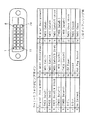
図11および図12は、共にDVI仕様のコネクタを示す図である。DVI仕様には図11に示すディジタル仕様の信号にのみ対応したインターフェースと、図12に示すディジタル仕様とアナログ仕様の信号の両方のインターフェースを備えるものの2種類が存在する。前者はDVI−D、後者はDVI−Iという。DVI仕様によれば、DDC通信に使用される信号ラインは2本であり、それぞれ、双方向のシリアルデータラインであるSDAラインと、クロックとして使用されるSCLラインである。また、DVI仕様において、DDC通信にはDDC2Bと呼ばれる通信プロトコルが使用される。
【0007】
コンピュータが、DVIコネクタの7番ピン(SDA)と6番ピン(SCL)を介してディスプレイモニタにEDIDデータを転送することを要求すると、ディスプレイモニタは、7番ピン(SDA)を介してEDIDデータのコンピュータへの転送を開始する。そしてコンピュータが、EDIDデータが十分転送されたと判断すると、EDIEデータ転送の停止をディスプレイモニタに要求し、それを受けてディスプレイモニタはEDIDデータの転送を停止する。
【0008】
ところで、図12に示したように、DVI−Iインターフェースの場合、ビデオ信号の入力インターフェースはディジタルチャンネルとアナログチャンネルの2系統あるのに対し、DDCラインは1系統しか存在しない。このため、DVI−I仕様のディスプレイモニタにおいては、コンピュータからのEDIDデータ転送要求に対して、アナログ仕様のEDIDデータを送るべきか、ディジタル仕様のEDIDデータを送るべきかの判断が困難となる。
【0009】
その問題を解決する方法として、ディスプレイモニタをアナログ仕様、ディジタル仕様のどちらのディスプレイモニタとして使用するかを、ユーザがあらかじめ選択することが挙げられる。そこで、従来よりDVI−Iインターフェースを有するディスプレイモニタとして、該ディスプレイモニタをアナログ仕様、ディジタル仕様のどちらのディスプレイモニタとして使用するかをユーザが設定するスイッチャーを有するものが提案されている。
【0010】
例えば、ディスプレイモニタをアナログ仕様として使用する場合、インターフェースの入力チャンネル、DDC通信で送信するEDIDデータをアナログ仕様に設定しなければならない。逆に、ディスプレイモニタをディジタル仕様として使用する場合、インターフェースの入力チャンネル、DDC通信で送信するEDIDデータをディジタル仕様に設定しなければならない。
【0011】
さらに、OSD(On Screen Display)による調整項目がアナログ仕様とディジタル仕様とで異なる場合(例えばアナログ仕様のディスプレイモニタのOSDにはクロックフェーズ調整項目が必要であるがアナログ仕様のディスプレイモニタのOSDには不要)は、それに応じてOSDも切り替える必要がある。
【0012】
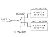
図13は従来のDVI−Iコネクタ仕様のディスプレイモニタのスイッチャーによるEDIDデータの切替を説明するための図である。この図に示すように、アナログ仕様のEDIDデータおよびディジタル仕様のEDIDデータのいずれかにアクセスできるようにDDCラインにスイッチャーが設けられる。ユーザは、ディスプレイモニタをアナログ仕様、ディジタル仕様のいずれのディスプレイモニタとして使用するかをOSD等で設定する。例えば、ユーザがアナログチャンネルを選択した場合はスイッチャーはアナログ仕様のEDIDデータ側に、ディジタルチャンネルを選択した場合はスイッチャーはディジタル仕様のEDIDデータ側に切り替わるように動作する。
【0013】
また、図示は省略したが、上述したように入力チャンネルやOSDの切り替えもスイッチャーの切り替えに連動して行なわれる。
【0014】
【発明が解決しようとする課題】
しかしながら、上記のようにアナログ/ディジタルチャンネルのどちらかに予め設定しておく方法では、例えばユーザが設定を誤ったり、ディスプレイモニタを接続するコンピュータの交換やコンピュータの設定の変更を行なった場合に、ディスプレイモニタがディジタルチャンネル設定であるにもかかわらずアナログ信号が入力されたり、アナログチャンネル設定であるにもかかわらずディジタル信号が入力されることが考えられる。従来のディスプレイモニタでは、そのようなケースには対応できないため、支援タイミングの不整合等により、表示が正しく行なわれないという不具合が生じる。
【0015】
また、ディジタルビデオ信号出力のあるコンピュータの中には、ディスプレイモニタが送出するEDIDデータがディジタル仕様でない場合、ディジタルビデオ信号出力を停止するものもあり、そのようなコンピュータに、図13に示した方法でアナログチャンネル側に選択されたディスプレイモニタが接続された場合、ディスプレイモニタにはビデオ信号が入力されず、何も表示されなくなるなどの問題が生じる。
【0016】
なお、ディスプレイモニタにおいて、入力されるビデオ信号は、コンピュータ側の出力形態により、D−Subコネクタのようなアナログのみのタイプ、DVI−DコネクタやDFPコネクタのようなディジタルのみのタイプ、そしてDVI−Iコネクタのようなデジタル/アナログ混在タイプを想定する必要がある。その理由は、例えばディスプレイモニタがDVI−Iコネクタ入力であっても、ビデオ信号の送り手であるコンピュータが必ずしもDVI−Iコネクタ出力とは限らず、例えばユーザが変換ケーブルもしくは変換コネクタを使用した場合、例えばDVI−Iコネクタ入力のディスプレイモニタにD−Subコネクタ出力など他の出力形態のコンピュータを接続することが可能であるからである。
【0017】
本発明は以上のような課題を解決するためになされたものであって、DVI−Iコネクタを備えるDDC機能を有するディスプレイモニタにおいて、入力チャンネルやEDIDデータ等の設定を入力信号の仕様に応じて自動的に正しく設定することのできる入力チャンネル切替制御装置を提供することを目的とする。
【0019】
【課題を解決するための手段】
請求項1に記載のディスプレイモニタ用入力チャンネル切替制御装置は、外部のコンピュータからのアナログ仕様およびディジタル仕様のビデオ信号のそれぞれに対応可能なDVI−Iインターフェースを備えるDDC機能を有するディスプレイモニタ用入力チャンネル切替制御装置であって、前記外部のコンピュータから入力される前記ビデオ信号がアナログ仕様かディジタル仕様かの判別および、入力チャンネルの状態がアナログチャンネルかディジタルチャンネルかの判別を行う判別手段と、アナログ仕様のEDIDデータおよびディジタル仕様のEDIDデータのそれぞれを記憶するEDIDデータ記憶手段と、前記入力チャンネルの状態を前記判別手段により判別された前記ビデオ信号の仕様のチャンネルに切り替える入力チャンネル切替手段と、前記外部のコンピュータからのDDC送信要求に基づいて、前記判別手段により判別された前記入力チャンネルの状態に対応した仕様のEDIDデータを前記EDIDデータ記憶手段から読み出して前記外部のコンピュータに送信するDDC制御手段とを備え、前記入力チャンネル切替手段は、前記DDC制御手段が前記EDIDデータを前記外部のコンピュータに送信した後で、前記入力チャンネルの状態を切り替えることを特徴とする。
【0020】
請求項2に記載のディスプレイモニタ用入力チャンネル切替制御装置は、請求項1に記載のディスプレイモニタ用入力チャンネル切替制御装置であって、前記入力チャンネル切替手段が、さらに、ユーザからの入力チャンネル切替要求に応じた前記入力チャンネルの状態の切り替えを行い、前記ユーザからの入力チャンネル切替要求よって前記入力チャンネルの状態が切り替わった場合に、前記外部のコンピュータとの接続コネクタにおけるホットプラグラインを所定の時間だけ開放するホットプラグライン割り込み手段をさらに備えることを特徴とする。
【0021】
請求項3に記載のディスプレイモニタ用入力チャンネル切替制御装置は、請求項2に記載のディスプレイモニタ用入力チャンネル切替制御装置であって、前記判別手段が、さらに、前記ディスプレイモニタにおける垂直帰線期間を判別し、前記入力チャンネル切替手段が、前記ユーザからのチャンネル切替要求に応じた前記入力チャンネルの状態の切り替えを、前記判別手段により判別された垂直帰線期間のタイミングで行うことを特徴とする。
【0022】
請求項4に記載のディスプレイモニタ用入力チャンネル切替制御装置は、外部のコンピュータからのアナログ仕様およびディジタル仕様のビデオ信号のそれぞれに対応可能なDVI−Iインターフェースを備えるDDC機能を有するディスプレイモニタ用入力チャンネル切替制御装置であって、前記外部のコンピュータから入力される前記ビデオ信号がアナログ仕様かディジタル仕様かの判別および、入力チャンネルの状態がアナログチャンネルかディジタルチャンネルかの判別を行う判別手段と、アナログ仕様のEDIDデータおよびディジタル仕様のEDIDデータのそれぞれを記憶するEDIDデータ記憶手段と、前記入力チャンネルの状態を前記判別手段により判別された前記ビデオ信号の仕様のチャンネルに切り替える入力チャンネル切替手段と、前記外部のコンピュータからのDDC送信要求に基づいて、所定の仕様のEDIDデータを前記EDIDデータ記憶手段から読み出して前記外部のコンピュータに送信するDDC制御手段と、前記DDC制御手段が前記EDIDデータ記憶手段から読み出す前記所定の仕様のEDIDデータを、前記判別手段により判別された前記ビデオ信号の仕様のEDIDデータにするか、前記判別手段により判別された前記入力チャンネルの状態に対応した仕様のEDIDデータにするかを選択可能な選択手段とを備え、前記選択手段によって前記入力チャンネルの状態に対応した仕様の前記EDIDデータが選択された場合、前記入力チャンネル切替手段は、前記DDC制御手段が前記EDIDデータを前記外部のコンピュータに送信した後で、前記入力チャンネルの状態を切り替えることを特徴とする。
【0024】
請求項5に記載のディスプレイモニタの入力チャンネル切替制御方法は、外部のコンピュータからのアナログ仕様およびディジタル仕様のビデオ信号のそれぞれに対応可能なDVI−Iインターフェースを備えるDDC機能を有するディスプレイモニタの入力チャンネル切替制御方法であって、(a)前記外部のコンピュータからのDDC送信要求を検出する工程と、(b)前記工程(a)において前記DDC送信要求が検出された場合に、入力チャンネルの状態がアナログチャンネルかディジタルチャンネルかの判別を行う工程と、(c)前記工程(b)において判別された前記入力チャンネルの状態に対応した仕様のEDIDデータを前記外部のコンピュータに送信する工程と、(d)前記工程(c)の後に行われ、前記外部のコンピュータから入力される前記ビデオ信号がアナログ仕様かディジタル仕様かの判別を行う工程と、(e)前記工程(b)において判別された前記入力チャンネルの状態に対応した仕様と前記工程(d)において判別された前記ビデオ信号の仕様とが異なる場合に、前記入力チャンネルの状態を前記工程(d)において判別された前記ビデオ信号の仕様のチャンネルに切り替え、前記工程(a)に戻る工程とを備えることを特徴とする。
【0025】
【発明の実施の形態】
<実施の形態1>
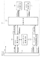
図1は本発明の実施の形態1に係るディスプレイモニタ用入力チャンネル切替制御装置50の構成図である。この図において、51は、アナログ仕様、ディジタル仕様の2系統の入力信号に対応したDVI−Iコネクタであり、ディスプレイモニタはDVI−Iコネクタ51を介して外部のコンピュータに接続される。52は、アナログ同期信号検出手段であり、DVI−Iコネクタ51のアナログ水平同期信号およびアナログ垂直同期信号を検出する。これらのアナログ水平および垂直同期信号は、外部のコンピュータからビデオ信号がアナログ仕様のときのみに送信されるものであるので、この信号を監視することで、その有無によりビデオ信号がディジタル仕様であるかアナログ仕様であるか判定できる。アナログ同期信号検出手段52は、アナログ水平および垂直同期信号を検出すると、判別手段53へアナログチャンネル入力検出信号を出力する。
【0026】
判別手段53は、アナログ同期信号検出手段52からのアナログチャンネル入力検出信号に基づき、ビデオ信号がアナログ仕様であるかディジタル仕様であるかを判別する。つまり、本実施の形態においては、アナログ同期信号検出手段52と判別手段53とで、入力ビデオ信号がディジタル信号であるかアナログ信号であるかを判別する手段を構成している。判別手段53は、そのビデオ信号の判別結果に基づき、DDC制御手段、入力チャンネル切替手段56、OSD切替手段57へ、それぞれDDC切替制御信号、入力チャンネル切替制御信号、OSD切替制御信号を送信する。
【0027】
54は、アナログ仕様のEDIDデータおよびディジタル仕様のEDIDデータが共に記憶されている不揮発性のEDIDデータ記憶手段である。DDC制御手段55は、コンピュータとのDDC通信を行い、DDC要求信号を検出した場合に判別手段53にDDC送信要求検出信号を送信する。そして、判別手段53からのDDC切替制御信号に基づき、ビデオ信号の仕様に対応したEDIDデータをEDIDデータ記憶手段54から読み込むように制御され、読み込んだEDIDデータをコンピュータに送信する。
【0028】
入力チャンネル切替手段56は、判別手段53からの入力チャンネル切替制御信号により制御され、入力チャンネルをビデオ信号の仕様に対応したチャンネルに切り替える。また、OSD切替手段57は、判別手段53からのOSD切替制御信号により制御され、ディスプレイモニタのOSDを判別手段53により判別されたビデオ信号の仕様に対応したOSDに切り替える。
【0029】
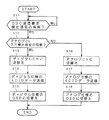
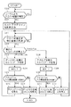
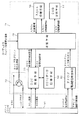
図2は、本実施の形態に係るディスプレイモニタ用入力チャンネル切替制御装置の動作を示すフローチャートである。以下、この図に基づいて図1の入力チャンネル切替制御装置の動作を説明する。
【0030】
判別手段53は、DDC制御手段55からのDDC送信要求検出信号の監視を行うことで、外部のコンピュータからのDDC送信要求の有無を監視する。(S11)。そして、DDC送信要求があり、DDC制御手段55から判別手段53へとDDC送信要求検出信号が送られると、判別手段53は引き続いてアナログ同期信号検出手段52からのアナログチャンネル入力検出信号の検出を行う(S12)。
【0031】
S12でアナログチャンネル入力検出信号が検出されない場合(即ち、入力ビデオ信号がディジタル仕様である場合)、判別手段53は入力チャンネル切替手段を制御して、入力チャンネルをディジタルチャンネルへと切り替える(S13)。さらに、判別手段53の制御に基づき、DDC制御手段55はディジタル仕様のEDIDデータをEDIDデータ記憶手段54より読み出してコンピュータに送信し(S14)、OSD切替手段57はディジタル対応のOSDに切り替える(S15)。
【0032】
また、S12でアナログチャンネル入力検出信号が検出された場合(即ち、入力ビデオ信号がアナログ仕様である場合)、判別手段53は、入力チャンネル切替手段を制御して入力チャンネルをアナログチャンネルへと切り替える(S16)。さらに、判別手段53の制御に基づき、DDC制御手段55はアナログ仕様のEDIDデータをEDIDデータ記憶手段54より読み出してコンピュータに送信し(S17)、OSD切替手段57はアナログ対応のOSDに切り替える(S18)。
【0033】
つまり、本実施の形態に係る入力チャンネル切替制御装置50によれば、DVI−Iコネクタ仕様に対応したディスプレイモニタにおいて、コンピュータが出力している信号がディジタル仕様の場合、ディスプレイモニタの送信EDIDデータ、入力チャンネル、OSDは全てディジタル仕様に対応したものに自動的に設定され、反対にコンピュータが出力している信号がアナログ仕様の場合、それらは全てアナログ仕様に対応したものに自動的に設定される。
【0034】
つまり、ディスプレイモニタの送信EDIDデータ、入力チャンネル、OSDは、コンピュータが出力している信号の仕様に対応したものに自動に切り替わる。
【0035】
これにより、コンピュータの出力信号の仕様とディスプレイモニタの入力チャンネルとの不整合による、支援タイミングの不整合や、OSDの調整項目が異なる問題(例えばアナログチャンネルのOSDにはクロックフェーズ調整項目が必要であるがディジタルチャンネルのOSDには不要)、また画面が何も表示されなくなるいという問題を回避することができる。
【0036】
<実施の形態2>
上述したように、実施の形態1では、ディスプレイモニタのEDIDデータ出力、入力チャンネル、OSDは、コンピュータが出力している信号の仕様に対応したものに自動に切り替わる。
【0037】
ところで、コンピュータ側も信号出力インターフェースとしてDVI−I仕様のインターフェースを有している場合、該コンピュータはビデオ信号としてアナログ仕様のものとディジタル仕様のものとの両方の出力が可能である。
【0038】
例えば、DVI−I仕様の出力インターフェースを有するコンピュータにアナログ仕様のディスプレイが接続された場合、コンピュータはアナログ仕様の信号を出力し、ディジタル仕様のディスプレイを接続した場合、コンピュータはディジタル仕様の信号を出力する動作が可能である。
【0039】
つまり、図13に示した従来のディスプレイモニタを接続した場合、コンピュータの出力信号の仕様は、ディスプレイモニタのスイッチャーの状態により決定される。つまり、コンピュータとの接続時に、ディスプレイモニタのスイッチャーがアナログ側を選択していればコンピュータの出力信号はアナログ仕様に切り替わり、逆にディジタル側を選択していればコンピュータの出力信号はディジタル仕様に切り替わる。つまり、ディスプレイモニタ側でビデオ信号の仕様を選択することができる。
【0040】
しかし、実施の形態1に係るディスプレイモニタは、コンピュータの出力信号の仕様によって、入力チャンネル等が強制的に切り替わってしまうので、上記のようなディスプレイモニタ側からビデオ信号の仕様を選択することはできない。
【0041】
そこで、本実施の形態においては、コンピュータ側のDVI−I仕様の出力インターフェースを有する場合にコンピュータ側の出力信号をディスプレイモニタ側で選択でき、また、他のインターフェースの場合にはディスプレイモニタの入力チャンネル、EDIDデータ、OSD等の設定を自動的に正しく設定できる入力チャンネル切替制御装置を提案する。
【0042】
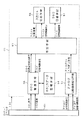
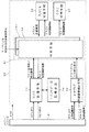
図3は本発明の実施の形態2に係るディスプレイモニタ用入力チャンネル切替制御装置60の構成図である。この図において、61はDVI−Iコネクタ51に接続されたコンピュータから入力される前記ビデオ信号がアナログ仕様かディジタル仕様かの判別および、入力チャンネルの状態の判別を行う判別手段である。ここで、判別手段61におけるビデオ信号の判別は、アナログ同期信号検出手段52からのアナログチャンネル入力検出信号に基づき行なわれ、入力チャンネルの状態の判別は、入力チャンネル切替手段が例えばEEPROM等に保持している入力チャンネル状態情報に基づいて行なわれる。なお、図3におけるその他の要素については、図1に同符号を用いて示した要素と同一であるので、ここでの詳細な説明は省略する。
【0043】
判別手段61は、ビデオ信号がアナログ仕様かディジタル仕様かの判別および、入力チャンネルの状態の判別の結果に基づいて、DDC制御手段、入力チャンネル切替手段56、OSD切替手段57へ、それぞれDDC切替制御信号、入力チャンネル切替制御信号、OSD切替制御信号を送信する。
【0044】
ただし、本実施の形態においては実施の形態1とは異なり、DDC制御手段55は判別手段61からのDDC切替制御信号により、そのときの入力チャンネルの状態に対応した仕様のEDIDデータをEDIDデータ記憶手段54から読み込むように制御される。また、入力チャンネル切替手段56およびOSD切替手段57は、実施の形態1と同様に、それぞれ入力チャンネル切替制御信号、OSD切替制御信号により制御され、入力チャンネルおよびOSDをビデオ信号の仕様に対応したものに切り替える。
【0045】
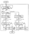
図4は、本実施の形態に係るディスプレイモニタ用入力チャンネル切替制御装置60の動作を示すフローチャートである。以下、この図に基づいて図3のチャンネル切替制御装置の動作を説明する。
【0046】
ここで、ディスプレイモニタに接続されるコンピュータの出力インターフェースの仕様として、アナログ仕様とディジタル仕様の両方の信号を出力できるDVI−I仕様の他、例えばD−Subのようなアナログ仕様の信号のみを出力するもの、DVI−Iのようなディジタル仕様の信号のみを出力するものが考えられる。下の表は、以下の説明における場合分けを示す表であり、接続されるコンピュータの出力形態と、ディスプレイモニタの入力チャンネルの初期状態(接続時にユーザによって設定された状態)との組み合わせにより、ケース1〜ケース6の6通りのケースが考えられる。
【0047】
【表1】
上記したように、本実施の形態においては、コンピュータ側のDVI−I仕様の出力インターフェースを有する場合にコンピュータ側の出力信号をディスプレイモニタ側で選択でき、また、他のインターフェースの場合にはディスプレイモニタの入力チャンネル、EDIDデータ、OSD等の設定を自動的に正しく設定するものであり、つまり、ディスプレイモニタはケース1〜ケース3ではディジタル仕様に、ケース4〜ケース6ではアナログ仕様に設定される。
【0049】
まず、ケース1の場合の動作について説明する。判別手段61は、DDC制御手段55からのDDC送信要求検出の検出を行うことで、コンピュータからのDDC送信要求の有無を監視する。(S21)。そして、コンピュータからのDDC送信要求があると、判別手段61はディスプレイモニタの現在の入力チャンネルの状態を判定する(S22)。ケース1では初期の入力チャンネルの設定はディジタルチャンネルとなっているので、DDC制御手段55は、判別手段61の制御に基づきディジタル仕様のEDIDデータをEDIDデータ記憶手段54より読み出してコンピュータに送信する(S23)。そして、DDC送信に対するコンピュータの応答を待つために所定の待機時間だけ待機し(S24)、その後、判別手段61はアナログ同期信号検出手段52からのアナログチャンネル入力検出信号の検出を行う(S25)。このときケース1ではコンピュータの出力形態はディジタル仕様の信号のみを出力するDFPやDVI−Dであるため、アナログチャンネル入力検出信号は検出されないので、判別手段61はOSD切替手段を制御してOSDをディジタル仕様のOSDに切り替える(S27)。このようにして、ケース1では入力チャンネル、EDIDデータ、OSDはディジタル仕様に設定される。
【0050】
次に、ケース2の場合の動作について説明する。S21でコンピュータからのDDC送信要求が検出されると、S22で判別手段61によりディスプレイモニタの現在の入力チャンネルの状態が判定される。ケース2では初期の入力チャンネルの設定はアナログチャンネルとなっているので、DDC制御手段55は、判別手段61の制御に基づきアナログ仕様のEDIDデータをEDIDデータ記憶手段54より読み出してコンピュータに送信する(S28)。そして、DDC送信に対するコンピュータの応答を待つために所定の待機時間だけ待機し(S29)、その後、判別手段61はアナログ同期信号検出手段52からのアナログチャンネル入力検出信号の検出を行う(S30)。このときケース2ではコンピュータの出力仕様はディジタル仕様のみであるのでアナログチャンネル入力検出信号は検出されず、入力チャンネルはディジタルチャンネルへと切り替えられ(S32)、再びS21に戻る。ここで、システム立ち上げ時等に行われるDDC送信要求は一般的に複数回行なわれるので再びDDC送信要求が検出されることとなるが、このときの入力チャンネルはディジタルチャンネルであり、つまりケース1の状態に遷移している。よってその後は、上記したケース1と同様の動作で、入力チャンネル、EDIDデータ、OSDはディジタル仕様に設定される。
【0051】
ケース3の場合の動作について説明する。S21でコンピュータからのDDC送信要求が検出されると、S22で判別手段61によりディスプレイモニタの現在の入力チャンネルの状態が判定される。ケース3では初期の入力チャンネルの設定はディジタルチャンネルとなっているので、DDC制御手段55は、判別手段61の制御に基づきディジタル仕様のEDIDデータをEDIDデータ記憶手段54より読み出してコンピュータに送信する(S23)。そして、DDC送信に対するコンピュータの応答を待つために所定の待機時間だけ待機し(S24)、その後、判別手段61はアナログ同期信号検出手段52からのアナログチャンネル入力検出信号の検出を行う(S25)。このときケース3ではコンピュータの出力仕様はディジタル仕様とアナログ仕様の両方に対応したDVI−I仕様であるが、S23においてディジタル仕様のEDIDデータを受けたコンピュータはディジタル仕様の信号を出力するのでアナログチャンネル入力検出信号は検出されず、OSDをディジタル仕様のOSDに切り替える(S27)。このようにして、ケース3では入力チャンネル、EDIDデータ、OSDはディジタル仕様に設定される。
【0052】
ケース4の場合の動作について説明する。S21でコンピュータからのDDC送信要求が検出されると、S22で判別手段61によりディスプレイモニタの現在の入力チャンネルの状態が判定される。ケース4では初期の入力チャンネルの設定はアナログチャンネルとなっているので、DDC制御手段55は、判別手段61の制御に基づきアナログ仕様のEDIDデータをEDIDデータ記憶手段54より読み出してコンピュータに送信する(S28)。そして、DDC送信に対するコンピュータの応答を待つために所定の待機時間だけ待機し(S29)、その後、判別手段61はアナログ同期信号検出手段52からのアナログチャンネル入力検出信号の検出を行う(S30)。このときケース4ではコンピュータの出力仕様はディジタル仕様とアナログ仕様の両方に対応したDVI−I仕様であるが、S28においてアナログ仕様のEDIDデータを受けたコンピュータはアナログ仕様の信号を出力するのでアナログチャンネル入力検出信号が検出され、OSDをアナログ仕様のOSDに切り替える(S31)。このようにして、ケース4では入力チャンネル、EDIDデータ、OSDはアナログ仕様に設定される。
【0053】
ここで、ケース5を説明する前に、便宜上ケース6を先に説明する。S21でコンピュータからのDDC送信要求が検出されると、S22で判別手段61によりディスプレイモニタの現在の入力チャンネルの状態が判定される。ケース6では初期の入力チャンネルの設定はアナログチャンネルとなっているので、DDC制御手段55は、判別手段61の制御に基づきアナログ仕様のEDIDデータをEDIDデータ記憶手段54より読み出してコンピュータに送信する(S28)。そして、DDC送信に対するコンピュータの応答を待つために所定の待機時間だけ待機し(S29)、その後、判別手段61はアナログ同期信号検出手段52からのアナログチャンネル入力検出信号の検出を行う(S30)。このときケース6ではコンピュータの出力仕様はアナログ仕様のみに対応したD−Sub仕様であるので、コンピュータはアナログ仕様の信号を出力するのでアナログチャンネル入力検出信号が検出され、OSDをアナログ仕様のOSDに切り替える(S31)。このようにして、ケース6では入力チャンネル、EDIDデータ、OSDはアナログ仕様に設定される。
【0054】
そして次に、ケース5の場合の動作について説明する。S21でコンピュータからのDDC送信要求が検出されると、S22で判別手段61によりディスプレイモニタの現在の入力チャンネルの状態が判定される。ケース5では初期の入力チャンネルの設定はディジタルチャンネルとなっているので、DDC制御手段55は、判別手段61の制御に基づきディジタル仕様のEDIDデータをEDIDデータ記憶手段54より読み出してコンピュータに送信する(S23)。そして、DDC送信に対するコンピュータの応答を待つために所定の待機時間だけ待機し(S24)、その後、判別手段61はアナログ同期信号検出手段52からのアナログチャンネル入力検出信号の検出を行う(S25)。このときケース3ではコンピュータの出力仕様はアナログ仕様のみに対応したD−Sub仕様であるので、S23においてディジタル仕様のEDIDデータを受けてもコンピュータはアナログ仕様の信号を出力するのでアナログチャンネル入力検出信号が検出され、入力チャンネルはアナログチャンネルへと切り替えられ(S26)、再びS21に戻る。ここで、システム立ち上げ時等に行われるDDC送信要求は一般的に複数回行なわれるので再びDDC送信要求が検出されることとなるが、このときの入力チャンネルはアナログチャンネルであり、つまりケース6の状態に遷移している。よってその後は、上記したケース6と同様の動作で、入力チャンネル、EDIDデータ、OSDはディジタル仕様に設定される。
【0055】
以上説明したように、本実施の形態に係るディスプレイモニタのチャンネル切替制御装置によれば、DVI−Iコネクタ仕様に対応したディスプレイモニタにおいて、コンピュータの出力形態がDVI−I出力を持つ場合、アナログ仕様かディジタル仕様のいずれのディスプレイモニタとして使用するかをディスプレイモニタ側の設定を優先して選択できる。さらに、アナログ仕様、ディジタル仕様のいずれかのみ出力可能なコンピュータに接続された場合は、実施の形態1と同様に、その出力信号の仕様に応じて、ディスプレイモニタの入力チャンネル、EDIDデータ、OSD等の設定を自動的に正しく設定できる。
【0056】
つまり、ディスプレイモニタのチャンネル設定を優先しつつ、コンピュータの出力信号の仕様とディスプレイモニタの入力チャンネルとの不整合による、支援タイミングの不整合や、OSDの調整項目が異なる問題(例えばアナログチャンネルのOSDにはクロックフェーズ調整項目が必要であるがディジタルチャンネルのOSDには不要)、また画面が何も表示されなくなるいという問題を回避することができる。
【0057】
<実施の形態3>
DVI−Iコネクタを有するディスプレイモニタにおいて、コンピュータおよびディスプレイモニタの使用中にユーザがOSD等によりディスプレイモニタの入力チャンネル切替を行った場合、支援タイミングの不整合等により、表示が正しく行われなくなる。その場合、再度DDC通信を行なわせるために、一度コンピュータリセットしたり、ディスプレイモニタとコンピュータとの接続を再度行う必要が生じる。例えば、上記した実施の形態2ではディスプレイモニタの設定を優先できるが、この問題によりディスプレイモニタの使用中におけるチャンネルの切り替えはできない。
【0058】
図5は、実施の形態3に係るディスプレイモニタ用入力チャンネル切替制御70の構成図である。この図において、71は、DVI−Iコネクタ51に接続されたコンピュータから入力される前記ビデオ信号がアナログ仕様かディジタル仕様かの判別および、入力チャンネルの状態の判別を行う判別手段である。また、72はDVI−Iコネクタ51の+5V端子とホットプラグ端子間をスイッチングするホットプラグライン割り込み手段であり、判別手段71のホットプラグライン割り込み信号により制御される。なお、その他の要素については、図3に同符号を用いて示した要素と同一であるので、ここでの詳細な説明は省略する。
【0059】
判別手段71は、入力チャンネルの状態を判別することで入力チャンネルの切替を検出することができ、入力チャンネルの切替を検出した場合、所定の時間だけホットプラグライン割り込み信号をハイレベルにすることで、ホットプラグライン割り込み手段をオフし、DVI−Iコネクタ51のホットプラグラインを開放状態にし、それまで+5Vにプルアップされていたホットプラグラインをローレベルにする。
【0060】
図6は、本実施の形態に係るディスプレイモニタ用入力チャンネル切替制御装置70の動作を示すフローチャートである。以下、この図に基づいて図5のチャンネル切替制御装置の動作を説明する。
【0061】
まず、判別手段71は、ディスプレイモニタの入力チャンネルの状態を監視することにより入力チャンネルの切り替えの有無を判定する(S33)。ここで、ユーザが例えばOSDを介してディスプレイモニタの入力チャンネルの切り替えを要求すると、入力チャンネル切替要求信号が入力チャンネル切替手段56に入力され、入力チャンネル切替手段56は入力チャンネルの状態を切り替える。判別手段71は入力チャンネルの状態の変化によりそれを検出し、所定の時間だけホットプラグライン割り込み手段72をオフし、DVI−Iコネクタ51のホットプラグラインを開放状態にして、それまで+5Vにプルアップされていたホットプラグラインをローレベルにする(S34)。
【0062】
通常、ホットプラグラインは、ディスプレイモニタ側で抵抗を介して+5V端子に電気的に接続されるので、コンピュータとディスプレイモニタが接続されることにより+5Vにプルアップされる。コンピュータ側では、このホットプラグラインのレベルによりディスプレイモニタが接続されたことを認識し、それによりディスプレイモニタに対してDDC送信要求を行っている。
【0063】
つまり、ホットプラグライン割り込み手段をオフすることでDVI−Iコネクタ51のホットプラグラインを開放状態にし、ホットプラグラインがローレベルになると、コンピュータ側から見てディスプレイモニタのコネクタが抜かれた状態と等価になる。そして所定の時間の後ホットプラグライン割り込み手段がオンされ、ホットプラグラインが再び+5Vにプルアップされると、コンピュータ側のグラフィックチップに割り込みがかけられ、コンピュータはディスプレイモニタが接続されたものと判断して、ディスプレイモニタに対しDDC送信要求を行う。よって、コンピュータのリセットやディスプレイモニタとコンピュータとの接続を再度行うこと無しに、コンピュータにDDC送信要求を行なわせることができる。
【0064】
なお、S34以降の動作は、実施の形態2において図4で説明したものと同一のためここでの説明を省略する。
【0065】
本実施の形態に係るディスプレイモニタの入力チャンネル切替制御装置によれば、DVI−Iコネクタ仕様に対応したディスプレイモニタにおいて、アナログ仕様かディジタル仕様のいずれのディスプレイモニタとして使用するかをディスプレイモニタ側の設定を優先して選択でき、さらにその使用中にユーザが入力チャンネルの切り替えを行なった場合、コンピュータのリセットやディスプレイモニタとコンピュータとの接続を再度行うこと無しにコンピュータにDDC送信要求を行なわせることができる。つまり、ユーザがディスプレイモニタの使用中に入力チャンネルの切り替えを行なった場合においても、表示モードの整合性を保つように動作させることができる。
【0066】
<実施の形態4>
実施の形態3に示したディスプレイモニタの入力チャンネル切替制御装置において、ユーザからの入力チャンネル切替要求による入力チャンネルの切り替えが行われている過程では、正常な表示を行うことができない。よって、その間は表示画面をブランキングしたり、あるいはフレームメモリを有するディスプレイモニタにおいては表示画像を入力チャンネル切り替え前の状態に固定したりすることで、画面表示の乱れを回避することが考えられる。
【0067】
しかし、実施の形態3においては、図5に示したようにユーザによる入力チャンネル切替要求信号が入力チャンネル切替手段に直接入力される。つまり、入力チャンネル切替手段による入力チャンネルの切り替えは、ユーザが入力チャンネル切替要求を行った任意のタイミングで強制的に行われるものであり、ディスプレイモニタの走査に同期したタイミングで行われるものではない。よって、そのタイミングによっては、入力チャンネルの切り替えと同時に行われるブランキングあるいは画像固定の前にディスプレイモニタの画面表示に乱れが生じることがある。そこで、入力チャンネルの切り替えの際、前もってブランキングあるいは画像固定をしておくことも考えられるが、画面のブランキングあるいは画像固定の期間がその分長くなってしまう。
【0068】
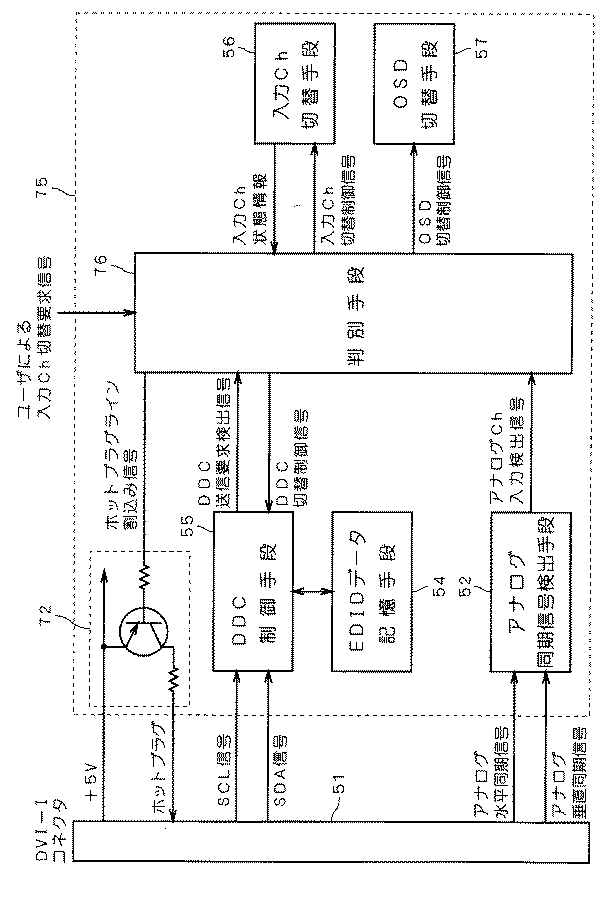
図7は、実施の形態4に係るディスプレイモニタ用入力チャンネル切替制御装置75の構成図である。この図において、76はDVI−Iコネクタ51に接続されたコンピュータから入力されるビデオ信号がアナログ仕様かディジタル仕様かの判別および、入力チャンネルの状態の判別、さらにディスプレイモニタの垂直帰線期間かどうかの判別を行う判別手段である。なお、その他の要素については、図5に同符号を用いて示した要素と同一であるので、ここでの詳細な説明は省略する。
【0069】
ここで、上述した入力チャンネルの切り替えと同時にブランキングあるいは画像固定を行う場合に生じる画面表示の乱れは、入力チャンネルの切り替えがディスプレイモニタの画像表示期間、即ち垂直走査期間に行われることに起因するものである。つまり、入力チャンネルの切り替えをディスプレイモニタの垂直帰線期間のタイミングで行うことで、その表示画面の乱れの発生を抑えることができる。
【0070】
ディスプレイモニタの垂直帰線期間かどうかの判別は、ディスプレイモニタの垂直走査に同期した信号、例えばディスプレイモニタが内部で生成する垂直同期信号(以下、垂直内部同期信号という)を検出することで可能であり、判別手段76は、垂直内部同期信号に基づき、ディスプレイモニタの垂直帰線期間であるかどうかの判別を行う。
【0071】
また、図7に示すように、ユーザによる入力チャンネルの切替要求信号は判別手段76に入力される。判別手段76は、ユーザによる入力チャンネル切替要求信号に応じて、入力チャンネル切替手段を制御して入力チャンネルを切り替えるが、このとき、入力チャンネルの切り替えはディスプレイモニタの垂直帰線期間のタイミングで行われる。よって、入力チャンネルの切り替えと同時にブランキングあるいは画像固定を行った場合における画面の乱れの発生は抑えられる。
【0072】
図8は、本実施の形態に係るディスプレイモニタ用入力チャンネル切替制御装置75の動作を示すフローチャートである。以下、この図に基づいて図7のチャンネル切替制御装置の動作を説明する。
【0073】
まず、判別手段71は、ユーザによる入力チャンネル切替要求信号の入力を監視することによりユーザからの入力チャンネル切替要求の有無を判定する(S35)。ここで、ユーザが例えばOSDを介してディスプレイモニタの入力チャンネルの切り替えを要求すると、判別手段76に入力チャンネル切替要求信号が入力され、判別手段76はそれを検出する。このとき、判別手段76はディスプレイモニタの垂直内部同期信号に基づき、該ディスプレイモニタが垂直帰線期間であるかどうかの判定を行う(S36)。そして、S36の判定に基づいて垂直帰線期間のタイミングで入力チャンネルの切り替えを行う(S37)。そして、所定の時間だけホットプラグライン割り込み手段72をオフし、DVI−Iコネクタ51のホットプラグラインを開放状態にして、それまで+5Vにプルアップされていたホットプラグラインをローレベルにする(S38)。
【0074】
なお、S38以降の動作は、実施の形態2において図4で説明したものと同一のためここでの説明を省略する。
【0075】
以上のように、本実施の形態によれば、ユーザの要求による入力チャンネルの切り替えをディスプレイモニタの垂直帰線期間のタイミングで行うので、入力チャンネルの切り替えの際の画面のブランキングあるいは画像固定を、入力チャンネルの切り替えと同時に行っても、画面表示に乱れが生じない。つまり、ブランキングあるいは画像固定の期間を長くすること無く、画面表示の乱れの発生を抑えることができる。
【0076】
なお、図7においては、判別手段76における垂直帰線期間かどうかの判別を、ディスプレイモニタが生成する垂直内部同期信号に基づいて行う構成を示したが、ディスプレイモニタの垂直走査に同期した信号であれば他の信号に基づいても垂直帰線期間かどうかの判別は可能であり、同様の効果が得られることは明らかである。
【0077】
<実施の形態5>
コンピュータの出力形態がDVI−Iの場合、実施の形態1のようにコンピュータの出力設定を優先するアルゴリズムと、実施の形態2のようにディスプレイモニタの設定を優先するアルゴリズムの2通りが考えられる。実施の形態5ではそのチャンネル切り替えのアルゴリズムをユーザが選択することができる入力チャンネル切替制御装置を提案する。
【0078】
図9は、実施の形態5に係るディスプレイモニタの入力チャンネル切替制御装置80の構成図である。入力チャンネル切替制御装置80は、図2のフローチャートで説明した判別アルゴリズムを持つ判別手段53と、図4で説明した判別アルゴリズムを持つ判別手段61の2つを備える。そして、ユーザの判別手段切替要求信号により判別手段53と、判別手段61のどちらか1つの判別手段が選択される。つまり、判別手段53と判別手段61を切り替えることにより、DDC制御手段55がEDIDデータ記憶手段54から読み出すEDIDデータの仕様を、入力チャンネルの状態の仕様にするか、ビデオ信号の仕様にするかを選択する選択手段81を構成している。なお、この図におけるその他の要素については、図1に示したものと同一であるため説明を省略する。
【0079】
ユーザはOSD等を介して判別手段81に判別手段切替え要求信号を送り、判別手段53、61のどちらか1つを選択する。特にコンピュータの出力形態がDVI−Iの場合、判別手段53を使えばコンピュータの出力信号の仕様にチャンネルが強制的に切り替わるが、逆に、判別手段61を使えばディスプレイモニタの現在の入力チャンネルに応じてコンピュータの出力を選択できる。
【0080】
つまり、本実施の形態に係るディスプレイモニタのチャンネル切替制御装置によれば、コンピュータの出力形態がDVI−I仕様である場合、コンピュータの出力設定を優先するか、ディスプレイモニタの設定を優先するかユーザが選択することができる。
【0081】
なお、本実施の形態においては、異なる判別アルゴリズムで構成される複数の判別手段として、図2のフローチャートで説明した判別アルゴリズムを持つ判別手段53と、図4で説明した判別アルゴリズムを持つ判別手段61の2を示したが、判別手段として他のアルゴリズムを持つものにも容易に適応できることは明らかである。
【0082】
<変形例>
ここで、以上の説明においては、判別手段において行われる外部のコンピュータからのビデオ信号がアナログ仕様かディジタル仕様かの判別を、DVI−Iコネクタから入力されるアナログ水同期平信号およびアナログ垂直同期信号の検出の有無に基づいて行う例を示した。言い換えれば、アナログ仕様の信号の入力の有無を判別の基準とし、アナログ信号が入力されないケースをディジタル仕様の信号が入力されているものとして判別するものであった。
【0083】
しかし、本発明の判別手段におけるビデオ信号の仕様を判別する方法は、そのような判別方法に限定されるものではなく、例えば、ディジタル仕様の信号の入力の有無を判別の基準としてもよい。以下にその例を示す。
【0084】
図10は、実施の形態1に示したディスプレイモニタのチャンネル切替制御装置において、判別手段における外部のコンピュータからのビデオ信号の仕様の判別を、ディジタル仕様の信号の入力の有無に基づいて行う変形例を示す図である。この図において、図1と同一の要素に対しては同一符号を付しており、ここでの詳細な説明は省略する。
【0085】
90は本変形例に係るディスプレイモニタ用チャンネル切替制御装置である。91はディスプレイモニタのTMDS(Transmission Minimized Differential Signaling)レシーバであり、DVI−Iコネクタ51から入力されるディジタル仕様の信号であるTMDS信号から、映像信号および音声信号、水平同期信号、垂直同期信号等を復調すると共にそれらを分離抽出するものである。92はディジタル同期信号検出手段であり、TMDSレシーバ92により抽出されたディジタル仕様の水平同期信号および垂直同期信号を検出した場合に、ディジタルチャンネル入力検出信号を判別手段93に出力する。判別手段93は、図1に示した判別手段53と同じ機能を有するものであるが、ビデオ信号がアナログ仕様であるかディジタル仕様であるかの判別は、ディジタル同期信号検出手段92からのディジタルチャンネル入力検出信号に基づいて行われる。
【0086】
TMDSレシーバ91により抽出されるディジタル水平および垂直同期信号は、外部のコンピュータからのビデオ信号がディジタル仕様のときのみに得られるものであるので、この信号を監視することで、その有無によりビデオ信号がディジタル仕様であるかアナログ仕様であるか判定できる。ディジタル同期信号検出手段92は、ディジタル水平および垂直同期信号を検出すると、判別手段93へディジタルチャンネル入力検出信号を出力する。そして判別手段93においてディジタルチャンネル入力検出信号に基づきビデオ信号の仕様が判別され、その判別結果に応じて実施の形態1と同様の動作が行われる。
【0087】
つまり、この構成においては、判別手段93における外部のコンピュータから入力されるビデオ信号がアナログ仕様かディジタル仕様かの判別は、ディジタル仕様の信号の入力の有無に基づき行われる。この場合、ディジタル信号が入力されないケースは、アナログ信号が入力されているものとして判別されることになる。
【0088】
このように、ビデオ信号の仕様の判別はディジタル仕様の信号の入力の有無に基づいても可能である。また、その判別をアナログ仕様の信号の入力の有無に基づいて行う場合と同様の効果を得ることができることは明らかである。
【0089】
またさらに、アナログ仕様とディジタル仕様の両方の水平および垂直同期信号を検出して、それらに基づきビデオ信号の仕様の判定を行う構成も可能であることは明らかである。その場合はビデオ信号の仕様をより正確に行うことが可能になる。
【0090】
なお、ここでは実施の形態1の変形例を示したが、この変形例、即ち判別手段におけるビデオ信号の仕様の判別をディジタル仕様の信号の入力の有無に基づいて行う構成は、上記した他の実施の形態にも適応可能であることは言うまでも無い。
【0093】
【発明の効果】
請求項1に記載のディスプレイモニタ用入力チャンネル切替装置によれば、外部のコンピュータから入力されるビデオ信号がアナログ仕様かディジタル仕様かの判別および、入力チャンネルの状態がアナログチャンネルかディジタルチャンネルかの判別を行う判別手段と、アナログ仕様のEDIDデータおよびディジタル仕様のEDIDデータのそれぞれを記憶するEDIDデータ記憶手段と、入力チャンネルの状態を判別手段により判別されたビデオ信号の仕様のチャンネルに切り替える入力チャンネル切替手段と、外部のコンピュータからのDDC送信要求に基づいて、判別手段により判別された入力チャンネルの状態に対応した仕様のEDIDデータをEDIDデータ記憶手段から読み出して外部のコンピュータに送信するDDC制御手段とを備え、前記入力チャンネル切替手段は、前記DDC制御手段が前記EDIDデータを前記外部のコンピュータに送信した後で、前記入力チャンネルの状態を切り替えるので、DVI−Iインターフェースを備えるDDC機能を有するディスプレイモニタにおいて、コンピュータの出力形態がDVI−I出力を持つ場合、アナログ仕様かディジタル仕様のいずれのディスプレイモニタとして使用するかをディスプレイモニタ側の設定を優先して選択できる。さらに、アナログ仕様、ディジタル仕様のいずれかのみ出力可能なコンピュータに接続された場合は、その出力信号の仕様に応じて、ディスプレイモニタの入力チャンネル、EDIDデータの設定を自動的に正しく設定できる。
【0094】
よって、ディスプレイモニタのチャンネル設定を優先しつつ、入力チャンネルおよびEDIDデータを適正に切り替えることで、コンピュータの出力信号の仕様とディスプレイモニタの入力チャンネルとの不整合による、支援タイミングの不整合や、また画面が何も表示されなくなるいという問題を回避することができ、正しい表示を得ることができる。
【0095】
請求項2に記載のディスプレイモニタ用入力チャンネル切替装置によれば、請求項1に記載のディスプレイモニタ用入力チャンネル切替制御装置において、前記入力チャンネル切替手段が、さらに、ユーザからの入力チャンネル切替要求に応じた前記入力チャンネルの状態の切り替えを行い、前記ユーザからの入力チャンネル切替要求よって前記入力チャンネルの状態が切り替わった場合に、前記外部のコンピュータとの接続コネクタにおけるホットプラグラインを所定の時間だけ開放するホットプラグライン割り込み手段をさらに備え、前記選択手段によって前記入力チャンネルの状態に対応した仕様の前記EDIDデータが選択された場合、前記入力チャンネル切替手段は、前記DDC制御手段が前記EDIDデータを前記外部のコンピュータに送信した後で、前記入力チャンネルの状態を切り替えるので、DVI−Iインターフェースを備えるDDC機能を有するディスプレイモニタにおいて、コンピュータの出力形態がDVI−I出力を持つ場合、アナログ仕様かディジタル仕様のいずれのディスプレイモニタとして使用するかを、コンピュータを再起動すること無しにユーザがディスプレイモニタ側で切り替えすることができる。
【0096】
請求項3に記載のディスプレイモニタ用入力チャンネル切替制御装置によれば、請求項2に記載のディスプレイモニタ用入力チャンネル切替制御装置において、前記判別手段が、さらに、前記ディスプレイモニタにおける垂直帰線期間を判別し、前記入力チャンネル切替手段が、前記ユーザからのチャンネル切替要求に応じた前記入力チャンネルの状態の切り替えを、前記判別手段により判別された垂直帰線期間のタイミングで行うので、入力チャンネルの状態の切り替えの際の画面のブランキングあるいは画像固定を、入力チャンネルの切り替えと同時に行っても、画面表示に乱れが生じない。よって、ブランキングあるいは画像固定の期間を長くすること無く、画面表示の乱れの発生を抑えることができる。
【0097】
請求項4に記載のディスプレイモニタ用入力チャンネル切替制御装置によれば、前記外部のコンピュータから入力される前記ビデオ信号がアナログ仕様かディジタル仕様かの判別および、前記入力チャンネルの状態がアナログチャンネルかディジタルチャンネルかの判別を行う判別手段と、アナログ仕様のEDIDデータおよびディジタル仕様のEDIDデータのそれぞれを記憶するEDIDデータ記憶手段と、前記入力チャンネルの状態を前記判別手段により判別された前記ビデオ信号の仕様のチャンネルに切り替える入力チャンネル切替手段と、前記外部のコンピュータからのDDC送信要求に基づいて、所定の仕様のEDIDデータを前記EDIDデータ記憶手段から読み出して前記外部のコンピュータに送信するDDC制御手段と、前記DDC制御手段が前記EDIDデータ記憶手段から読み出す前記所定の仕様のEDIDデータを、前記判別手段により判別された前記ビデオ信号の仕様のEDIDデータにするか、前記判別手段により判別された前記入力チャンネルの状態に対応した仕様のEDIDデータにするかを選択可能な選択手段とを備えるので、コンピュータの出力形態がDVI−I出力を持つ場合、アナログ仕様かディジタル仕様のいずれのディスプレイモニタとして使用するかをディスプレイモニタ側の設定を優先させるか、あるいは、コンピュータからのビデオ信号の仕様を優先させるかを選択できる。
【0100】
請求項5に記載のディスプレイモニタの入力チャンネル切替制御方法によれば、外部のコンピュータからのアナログ仕様およびディジタル仕様のビデオ信号のそれぞれに対応可能なDVI−Iインターフェースを備えるDDC機能を有するディスプレイモニタの入力チャンネル切替制御方法であって、(a)外部のコンピュータからのDDC送信要求を検出する工程と、(b)工程(a)においてDDC送信要求が検出された場合に、入力チャンネルの状態がアナログチャンネルかディジタルチャンネルかの判別を行う工程と、(c)工程(b)において判別された入力チャンネルの状態に対応した仕様のEDIDデータを外部のコンピュータに送信する工程と、(d)工程(c)の後に行われ、外部のコンピュータから入力されるビデオ信号がアナログ仕様かディジタル仕様かの判別を行う工程と、(e)工程(b)において判別された入力チャンネルの状態に対応した仕様と工程(d)において判別されたビデオ信号の仕様とが異なる場合に、入力チャンネルの状態を工程(d)において判別されたビデオ信号の仕様のチャンネルに切り替え、工程(a)に戻る工程とを備えるので、DVI−Iインターフェースを備えるDDC機能を有するディスプレイモニタにおいて、コンピュータの出力形態がDVI−I出力を持つ場合、アナログ仕様かディジタル仕様のいずれのディスプレイモニタとして使用するかをディスプレイモニタ側の設定を優先して選択できる。さらに、アナログ仕様、ディジタル仕様のいずれかのみ出力可能なコンピュータに接続された場合は、その出力信号の仕様に応じて、ディスプレイモニタの入力チャンネル、EDIDデータの設定を正しく設定できる。
【0101】
よって、ディスプレイモニタのチャンネル設定を優先しつつ、入力チャンネルおよびEDIDデータを適正に切り替えることで、コンピュータの出力信号の仕様とディスプレイモニタの入力チャンネルとの不整合による、支援タイミングの不整合や、また画面が何も表示されなくなるいという問題を回避することができ、正しい表示を得ることができる。
【図面の簡単な説明】
【図1】 実施の形態1に係るディスプレイモニタ用入力チャンネル切替制御装置の構成図である。
【図2】 実施の形態1に係るディスプレイモニタ用入力チャンネル切替制御装置の動作を示すフローチャートである。
【図3】 実施の形態2に係るディスプレイモニタ用入力チャンネル切替制御装置の構成図である。
【図4】 実施の形態2に係るディスプレイモニタ用入力チャンネル切替制御装置の動作を示すフローチャートである。
【図5】 実施の形態3に係るディスプレイモニタ用入力チャンネル切替制御装置の構成図である。
【図6】 実施の形態3に係るディスプレイモニタ用入力チャンネル切替制御装置の動作を示すフローチャートである。
【図7】 実施の形態4に係るディスプレイモニタ用入力チャンネル切替制御装置の構成図である。
【図8】 実施の形態4に係るディスプレイモニタ用入力チャンネル切替制御装置の動作を示すフローチャートである。
【図9】 実施の形態5に係るディスプレイモニタ用入力チャンネル切替制御装置の構成図である。
【図10】 実施の形態1に示したディスプレイモニタのチャンネル切替制御装置の変形例を示す図である。
【図11】 DVI−D仕様のコネクタを示す図である。
【図12】 DVI−I仕様のコネクタを示す図である。
【図13】 従来のDVI−Iコネクタ仕様のディスプレイモニタのスイッチャーによるチャンネル切替を説明するための図である。
【符号の説明】
50,60,70,75,80,90 入力チャンネル切替制御装置、51 DVI−Iコネクタ、52 アナログ同期信号検出手段、53,61,71,76,93 判別手段、54 EDIDデータ記憶手段、55 DDC制御手段、56 入力チャンネル切替手段、57 OSD切替手段、72 ホットプラグライン割り込み手段、81 選択手段、91 TMDSレシーバ、92 ディジタル同期信号検出手段。[0001]
BACKGROUND OF THE INVENTION
The present invention relates to a display monitor having a DDC (Display Data Channel) function, and more particularly to a channel switching control device for a display monitor having a DVI-I interface capable of inputting analog and digital video signals. It is.
[0002]
[Prior art]
The DDC function is a function defined in the DDC standard for realizing an automatic environment setting function, a so-called plug and play method, on a computer system. According to the DDC standard, signal lines and procedures for exchanging data between a computer and a display monitor are defined. In other words, when a display monitor that supports the DDC standard is connected to a computer, the computer uses the DDC communication with the display monitor to display information related to the display monitor required for plug and play (hereinafter referred to as EDID (= Extended Display IDentification)). ) Can be taken out.
[0003]
This EDID data is stored in a nonvolatile memory such as an EEPROM (Electrically Erasable and Programmable Read Only Memory) inside the display monitor, and includes information such as manufacturer / product ID, display monitor specifications, and support timing.
[0004]
Conventionally, an analog interface represented by a D-Sub connector specification has been used as an interface of a display monitor. However, many flat displays such as a liquid crystal display (LCD) are digital interfaces. For example, when a display such as an LCD having a digital interface is connected to a computer having an output of a D-Sub specification, the analog / digital of the video signal is displayed. There are concerns about deterioration of display quality due to conversion and an increase in the cost of the apparatus, and expectations for standardization of digital interfaces are increasing.
[0005]
DVI (Digital Visual Interface) is a digital interface established by DDWG (Digital Display Working Group), and the digital data transfer method uses three channels of image data transmission paths (red, green, blue) and one channel. TMDS (Transition Minimized Differential Signaling), which is a system in which a serial signal of each transmission line is sent as a single-ended differential signal, is adopted.
[0006]
11 and 12 are both diagrams showing a connector of DVI specification. There are two types of DVI specifications: an interface corresponding only to digital specification signals shown in FIG. 11 and an interface including both digital specification and analog specification signals shown in FIG. The former is called DVI-D and the latter is called DVI-I. According to the DVI specification, there are two signal lines used for DDC communication, an SDA line that is a bidirectional serial data line and an SCL line that is used as a clock. In the DVI specification, a communication protocol called DDC2B is used for DDC communication.
[0007]
When the computer requests that the EDID data be transferred to the display monitor via pins 7 (SDA) and 6 (SCL) of the DVI connector, the display monitor sends EDID data via pin 7 (SDA). Start transferring to your computer. When the computer determines that the EDID data has been sufficiently transferred, the computer requests the display monitor to stop the EDIE data transfer, and in response thereto, the display monitor stops the transfer of the EDID data.
[0008]
Incidentally, as shown in FIG. 12, in the case of the DVI-I interface, there are two video signal input interfaces, digital channels and analog channels, whereas there is only one DDC line. Therefore, in a DVI-I specification display monitor, it is difficult to determine whether analog specification EDID data or digital specification EDID data should be sent in response to an EDID data transfer request from a computer.
[0009]
As a method for solving the problem, the user may select in advance whether to use the display monitor as an analog or digital display monitor. Therefore, conventionally, a display monitor having a DVI-I interface has been proposed that has a switcher that allows a user to set whether to use the display monitor as an analog or digital display monitor.
[0010]
For example, when the display monitor is used as an analog specification, the interface input channel and EDID data transmitted by DDC communication must be set to the analog specification. On the other hand, when the display monitor is used as a digital specification, the input channel of the interface and the EDID data transmitted by DDC communication must be set to the digital specification.
[0011]
Furthermore, when the adjustment items by OSD (On Screen Display) are different between the analog specification and the digital specification (for example, the OSD of the analog specification display monitor requires the clock phase adjustment item, but the OSD of the analog specification display monitor has Unnecessary) needs to switch the OSD accordingly.
[0012]
FIG. 13 is a diagram for explaining switching of EDID data by a switcher of a conventional display monitor having a DVI-I connector specification. As shown in this figure, a switcher is provided on the DDC line so that either analog EDID data or digital EDID data can be accessed. The user sets by OSD or the like whether the display monitor is used as an analog or digital display monitor. For example, when the user selects an analog channel, the switcher operates to switch to the analog EDID data side, and when the user selects a digital channel, the switcher operates to switch to the digital EDID data side.
[0013]
Although not shown in the figure, as described above, switching of the input channel and OSD is also performed in conjunction with switching of the switcher.
[0014]
[Problems to be solved by the invention]
However, in the method of setting the analog / digital channel in advance as described above, for example, when the user makes a setting mistake, changes the computer connected to the display monitor, or changes the computer setting, It is conceivable that an analog signal is input even if the display monitor is set to the digital channel, or a digital signal is input regardless of the analog channel setting. The conventional display monitor cannot cope with such a case, so that the display is not correctly performed due to inconsistency of the support timing.
[0015]
Also, some computers with digital video signal output stop the digital video signal output when the EDID data sent from the display monitor is not of a digital specification. In such a computer, the method shown in FIG. When the display monitor selected on the analog channel side is connected, a video signal is not input to the display monitor and nothing is displayed.
[0016]
In a display monitor, an input video signal may be an analog only type such as a D-Sub connector, a digital only type such as a DVI-D connector or a DFP connector, and a DVI- It is necessary to assume a digital / analog mixed type such as an I connector. The reason is that, for example, even if the display monitor is a DVI-I connector input, the computer that is the video signal sender is not necessarily the DVI-I connector output. For example, the user uses a conversion cable or a conversion connector. This is because, for example, it is possible to connect a computer having another output form such as a D-Sub connector output to a display monitor having a DVI-I connector input.
[0017]
The present invention has been made to solve the above-described problems. In a display monitor having a DDC function having a DVI-I connector, the input channel, EDID data, and the like are set according to the specifications of the input signal. An object of the present invention is to provide an input channel switching control device that can automatically set correctly.
[0019]
[Means for Solving the Problems]
Claim 1The display monitor input channel switching control device described in 1) is a display monitor input channel switching control device having a DDC function having a DVI-I interface capable of handling analog and digital video signals from an external computer. A discriminating means for discriminating whether the video signal inputted from the external computer is an analog specification or a digital specification, and discriminating whether an input channel is in an analog channel or a digital channel; and analog specification EDID data And EDID data storage means for storing each of the digital specification EDID data, and input channel switching for switching the state of the input channel to the video signal specification channel determined by the determination means And, based on a DDC transmission request from the external computer, reads out EDID data having a specification corresponding to the state of the input channel determined by the determination unit from the EDID data storage unit and transmits it to the external computer DDC control means forThe input channel switching means switches the state of the input channel after the DDC control means transmits the EDID data to the external computer.It is characterized by that.
[0020]
Claim 2The display monitor input channel switching control device described inClaim 1The display monitor input channel switching control device according to
[0021]
Claim 3The display monitor input channel switching control device described inClaim 2The display monitor input channel switching control device according to
[0022]
Claim 4The display monitor input channel switching control device described in 1) is a display monitor input channel switching control device having a DDC function having a DVI-I interface capable of handling analog and digital video signals from an external computer. A discriminating means for discriminating whether the video signal inputted from the external computer is an analog specification or a digital specification, and discriminating whether an input channel is in an analog channel or a digital channel; and analog specification EDID data And EDID data storage means for storing each of the digital specification EDID data, and input channel switching for switching the state of the input channel to the video signal specification channel determined by the determination means And DDC control means for reading out EDID data of a predetermined specification from the EDID data storage means and transmitting it to the external computer based on a DDC transmission request from the external computer, and the DDC control means includes the EDID The EDID data of the predetermined specification read from the data storage means is EDID data of the specification of the video signal determined by the determination means, or a specification corresponding to the state of the input channel determined by the determination means. With selection means that can select whether to use EDID dataWhen the EDID data having a specification corresponding to the state of the input channel is selected by the selection unit, the input channel switching unit is configured such that after the DDC control unit transmits the EDID data to the external computer, Switch the state of the input channelIt is characterized by that.
[0024]
Claim 5An input channel switching control method for a display monitor having a DDC function having a DVI-I interface capable of corresponding to each of analog and digital video signals from an external computer. And (a) detecting a DDC transmission request from the external computer, and (b) whether the input channel state is an analog channel when the DDC transmission request is detected in the step (a). Determining whether the channel is a digital channel, (c) transmitting EDID data having specifications corresponding to the state of the input channel determined in step (b) to the external computer, and (d) the step After (c), from the external computer A step of determining whether the video signal to be input is an analog specification or a digital specification; and (e) a specification corresponding to the state of the input channel determined in the step (b) and a determination in the step (d). A step of switching the state of the input channel to the channel of the video signal specification determined in the step (d) when the video signal specification is different, and returning to the step (a). Features.
[0025]
DETAILED DESCRIPTION OF THE INVENTION
<
FIG. 1 is a configuration diagram of a display monitor input channel
[0026]
The discriminating means 53 discriminates whether the video signal is analog or digital based on the analog channel input detection signal from the analog sync
[0027]
[0028]
The input channel switching means 56 is controlled by the input channel switching control signal from the discrimination means 53, and switches the input channel to a channel corresponding to the video signal specification. The
[0029]
FIG. 2 is a flowchart showing the operation of the display monitor input channel switching control device according to the present embodiment. Hereinafter, the operation of the input channel switching control device of FIG. 1 will be described with reference to FIG.
[0030]
The
[0031]
When the analog channel input detection signal is not detected in S12 (that is, when the input video signal has a digital specification), the discrimination means 53 controls the input channel switching means to switch the input channel to the digital channel (S13). Further, based on the control of the discriminating means 53, the DDC control means 55 reads the digital specification EDID data from the EDID data storage means 54 and transmits it to the computer (S14), and the OSD switching means 57 switches to the digital OSD (S15). ).
[0032]
When an analog channel input detection signal is detected in S12 (that is, when the input video signal has an analog specification), the
[0033]
That is, according to the input channel
[0034]
That is, the transmission EDID data, input channel, and OSD of the display monitor are automatically switched to those corresponding to the specifications of the signal output from the computer.
[0035]
As a result, problems such as inconsistency in support timing due to inconsistencies between computer output signal specifications and display monitor input channels, and different OSD adjustment items (for example, an analog channel OSD requires a clock phase adjustment item). (This is not necessary for the digital channel OSD), and the problem that nothing is displayed on the screen can be avoided.
[0036]
<
As described above, in the first embodiment, the EDID data output, the input channel, and the OSD of the display monitor are automatically switched to those corresponding to the specifications of the signal output by the computer.
[0037]
By the way, when the computer side also has a DVI-I specification interface as a signal output interface, the computer can output both analog and digital output video signals.
[0038]
For example, when an analog display is connected to a computer having a DVI-I specification output interface, the computer outputs an analog specification signal. When a digital display is connected, the computer outputs a digital specification signal. Is possible.
[0039]
That is, when the conventional display monitor shown in FIG. 13 is connected, the specification of the output signal of the computer is determined by the state of the switcher of the display monitor. In other words, if the display monitor switcher selects the analog side when connected to the computer, the computer output signal switches to the analog specification, and conversely if the digital side is selected, the computer output signal switches to the digital specification. . That is, the specification of the video signal can be selected on the display monitor side.
[0040]
However, in the display monitor according to the first embodiment, the input channel or the like is forcibly switched depending on the specification of the output signal of the computer, and thus the specification of the video signal cannot be selected from the display monitor side as described above. .
[0041]
Therefore, in this embodiment, when the computer has a DVI-I specification output interface on the computer side, the output signal on the computer side can be selected on the display monitor side, and in the case of other interfaces, the input channel of the display monitor can be selected. An input channel switching control device capable of automatically and correctly setting EDID data, OSD, etc. is proposed.
[0042]
FIG. 3 is a configuration diagram of the display monitor input channel
[0043]
The discriminating means 61 controls the DDC switching to the DDC control means, the input channel switching means 56, and the OSD switching means 57, respectively, based on the discrimination result of whether the video signal is analog specification or digital specification and the input channel state discrimination. A signal, an input channel switching control signal, and an OSD switching control signal are transmitted.
[0044]
However, in the present embodiment, unlike the first embodiment, the DDC control means 55 stores the EDID data of the specification corresponding to the state of the input channel at that time by the DDC switching control signal from the discrimination means 61. It is controlled to read from the
[0045]
FIG. 4 is a flowchart showing the operation of the display monitor input channel
[0046]
Here, as the specification of the output interface of the computer connected to the display monitor, in addition to the DVI-I specification capable of outputting both analog and digital signals, only analog specification signals such as D-Sub are output. It is possible to output only digital signals such as DVI-I. The table below shows the classification of cases in the following description, depending on the combination of the output form of the connected computer and the initial state of the input channel of the display monitor (the state set by the user at the time of connection). Six cases of 1 to 6 are conceivable.
[0047]
[Table 1]
As described above, in this embodiment, when the computer has a DVI-I specification output interface on the computer side, the output signal on the computer side can be selected on the display monitor side, and in the case of other interfaces, the display monitor can be selected. The input monitor, EDID data, OSD, etc. are automatically set correctly. That is, the display monitor is set to digital specifications in
[0049]
First, the operation in
[0050]
Next, the operation in
[0051]
The operation in
[0052]
The operation in
[0053]
Here, before describing the
[0054]
Next, the operation in
[0055]
As described above, according to the display monitor channel switching control device according to the present embodiment, in the display monitor corresponding to the DVI-I connector specification, when the computer output form has the DVI-I output, the analog specification. It is possible to preferentially select the display monitor side to use as a display monitor of digital specification. Furthermore, when connected to a computer that can output only analog or digital specifications, the display monitor input channel, EDID data, OSD, etc., according to the output signal specifications, as in the first embodiment. Can be set correctly automatically.
[0056]
In other words, priority is given to the channel setting of the display monitor, but there is a problem of mismatch in support timing due to inconsistency between the specifications of the output signal of the computer and the input channel of the display monitor, and different OSD adjustment items (for example, the OSD of the analog channel In this case, a clock phase adjustment item is necessary, but it is not necessary for the OSD of the digital channel), and the problem that nothing is displayed on the screen can be avoided.
[0057]
<
In a display monitor having a DVI-I connector, when the user switches the input channel of the display monitor using the OSD or the like while using the computer and the display monitor, the display is not correctly performed due to inconsistency of support timing. In that case, in order to perform DDC communication again, it is necessary to reset the computer once or to connect the display monitor and the computer again. For example, in the second embodiment described above, the setting of the display monitor can be prioritized, but due to this problem, the channel cannot be switched while the display monitor is being used.
[0058]
FIG. 5 is a configuration diagram of the display monitor input
[0059]
The discriminating means 71 can detect the switching of the input channel by discriminating the state of the input channel. When the switching of the input channel is detected, the hot plug line interrupt signal is set to the high level for a predetermined time. Then, the hot plug line interrupt means is turned off, the hot plug line of the DVI-
[0060]
FIG. 6 is a flowchart showing the operation of the display monitor input channel
[0061]
First, the determination means 71 determines whether or not the input channel is switched by monitoring the state of the input channel of the display monitor (S33). Here, when the user requests switching of the input channel of the display monitor, for example, via the OSD, an input channel switching request signal is input to the input
[0062]
Normally, the hot plug line is electrically connected to the + 5V terminal via a resistor on the display monitor side, so that it is pulled up to + 5V when the computer and the display monitor are connected. The computer recognizes that the display monitor is connected based on the level of the hot plug line, and makes a DDC transmission request to the display monitor.
[0063]
That is, when the hot plug line interrupt means is turned off to open the hot plug line of the DVI-
[0064]
Since the operation after S34 is the same as that described in FIG. 4 in the second embodiment, the description thereof is omitted here.
[0065]
According to the display monitor input channel switching control apparatus according to the present embodiment, in the display monitor corresponding to the DVI-I connector specification, it is set on the display monitor side whether to use as an analog specification or digital specification display monitor. If the user switches the input channel during use, the computer can make a DDC transmission request without resetting the computer or reconnecting the display monitor to the computer. it can. That is, even when the user switches the input channel while using the display monitor, the display mode can be operated so as to maintain consistency.
[0066]
<
In the input channel switching control device of the display monitor shown in the third embodiment, normal display cannot be performed in the process of switching the input channel according to the input channel switching request from the user. Therefore, it is conceivable to avoid disturbance of the screen display by blanking the display screen during that time or fixing the display image to the state before switching the input channel in a display monitor having a frame memory.
[0067]
However, in the third embodiment, as shown in FIG. 5, a user input channel switching request signal is directly input to the input channel switching means. That is, the input channel switching by the input channel switching means is forcibly performed at an arbitrary timing when the user makes an input channel switching request, and is not performed at a timing synchronized with the scanning of the display monitor. Therefore, depending on the timing, the screen display of the display monitor may be disturbed before blanking or image fixing performed simultaneously with the switching of the input channel. Therefore, it is conceivable to perform blanking or image fixing in advance when switching the input channel, but the blanking period or image fixing period of the screen becomes longer accordingly.
[0068]
FIG. 7 is a configuration diagram of the display monitor input channel
[0069]
Here, the disturbance of the screen display that occurs when blanking or image fixing is performed simultaneously with the switching of the input channel described above is caused by the switching of the input channel being performed during the image display period of the display monitor, that is, the vertical scanning period. Is. That is, by switching the input channel at the timing of the vertical blanking period of the display monitor, it is possible to suppress the occurrence of the disturbance of the display screen.
[0070]
Whether the display monitor is in the vertical blanking period can be determined by detecting a signal synchronized with the vertical scan of the display monitor, for example, a vertical synchronization signal (hereinafter referred to as a vertical internal synchronization signal) generated internally by the display monitor. Yes, the determination means 76 determines whether it is a vertical blanking period of the display monitor based on the vertical internal synchronization signal.
[0071]
Further, as shown in FIG. 7, the input channel switching request signal by the user is input to the determination means 76. The discriminating means 76 controls the input channel switching means to switch the input channel according to the input channel switching request signal from the user. At this time, the input channel is switched at the timing of the vertical blanking period of the display monitor. . Therefore, the occurrence of screen distortion when blanking or image fixing is performed simultaneously with switching of input channels can be suppressed.
[0072]
FIG. 8 is a flowchart showing the operation of the display monitor input channel
[0073]
First, the determination means 71 determines whether or not there is an input channel switching request from the user by monitoring the input of the input channel switching request signal by the user (S35). Here, when the user requests switching of the input channel of the display monitor via, for example, the OSD, an input channel switching request signal is input to the determining
[0074]
Since the operation after S38 is the same as that described in FIG. 4 in the second embodiment, the description thereof is omitted here.
[0075]
As described above, according to the present embodiment, since the input channel is switched at the request of the user at the timing of the vertical blanking period of the display monitor, screen blanking or image fixing at the time of switching the input channel is performed. Even if it is done at the same time as switching the input channel, the screen display will not be disturbed. That is, the occurrence of screen display disturbance can be suppressed without increasing the blanking or image fixing period.
[0076]
Although FIG. 7 shows a configuration in which the
[0077]
<
When the computer output form is DVI-I, two types of algorithms are conceivable: an algorithm that prioritizes computer output settings as in the first embodiment and an algorithm that prioritizes display monitor settings as in the second embodiment. The fifth embodiment proposes an input channel switching control device that allows the user to select the channel switching algorithm.
[0078]
FIG. 9 is a configuration diagram of an input channel
[0079]
The user sends a discrimination means switching request signal to the discrimination means 81 via the OSD or the like, and selects one of the discrimination means 53 and 61. In particular, when the output form of the computer is DVI-I, if the discriminating means 53 is used, the channel is forcibly switched to the output signal specification of the computer. Conversely, if the discriminating means 61 is used, the current input channel of the display monitor is set. The computer output can be selected accordingly.
[0080]
That is, according to the display monitor channel switching control device according to the present embodiment, when the computer output format is the DVI-I specification, whether the computer output setting is given priority or the display monitor setting is given priority. Can be selected.
[0081]
In the present embodiment, as a plurality of discriminating units constituted by different discriminating algorithms, a discriminating
[0082]
<Modification>
Here, in the above description, it is determined whether the video signal from the external computer is analog specification or digital specification, which is performed in the determination means. The analog horizontal synchronization signal and the analog vertical synchronization signal input from the DVI-I connector. An example of performing based on the presence or absence of detection is shown. In other words, whether or not an analog signal is input is used as a criterion for determination, and a case where an analog signal is not input is determined as a digital signal being input.
[0083]
However, the method of discriminating the video signal specification in the discriminating means of the present invention is not limited to such a discriminating method. For example, the presence / absence of input of a digital specification signal may be used as a criterion for discrimination. An example is shown below.
[0084]
FIG. 10 shows a modification of the display monitor channel switching control apparatus shown in the first embodiment in which the discrimination of the video signal specification from the external computer in the discrimination means is performed based on the presence or absence of the input of the digital specification signal. FIG. In this figure, the same elements as those in FIG. 1 are denoted by the same reference numerals, and detailed description thereof is omitted here.
[0085]
[0086]
Since the digital horizontal and vertical synchronization signals extracted by the
[0087]
That is, in this configuration, the determination means 93 determines whether the video signal input from an external computer is analog or digital, based on whether or not a digital signal is input. In this case, a case where a digital signal is not input is determined as an analog signal being input.
[0088]
As described above, the specification of the video signal can be determined based on whether or not a digital signal is input. In addition, it is obvious that the same effect can be obtained as in the case where the discrimination is performed based on whether or not an analog specification signal is input.
[0089]
Further, it is obvious that a configuration is possible in which horizontal and vertical synchronization signals of both analog specifications and digital specifications are detected, and video signal specifications are determined based on them. In that case, the specification of the video signal can be performed more accurately.
[0090]
Although a modification of the first embodiment is shown here, this modification, that is, a configuration in which the discrimination of the video signal specification in the discrimination means based on the presence / absence of input of a digital specification signal is described above. Needless to say, the present invention can also be applied to the embodiment.
[0093]
【The invention's effect】
Claim 1For display monitor as described ininputAccording to the channel switching device, the determination means for determining whether the video signal inputted from the external computer is analog specification or digital specification, the determination of whether the state of the input channel is analog channel or digital channel, and the analog specification EDID EDID data storage means for storing data and digital specification EDID data, input channel switching means for switching the input channel state to the video signal specification channel determined by the determination means, and DDC transmission from an external computer DDC control means for reading out EDID data having specifications corresponding to the state of the input channel determined by the determination means based on the request from the EDID data storage means and transmitting the data to an external computer.The input channel switching means switches the state of the input channel after the DDC control means transmits the EDID data to the external computer.Therefore, in a display monitor having a DDC function equipped with a DVI-I interface, if the computer output form has a DVI-I output, the display monitor side must be set as an analog or digital display monitor. Priority can be selected. Furthermore, when connected to a computer that can output only analog or digital specifications, the display monitor input channel and EDID data can be automatically set correctly according to the output signal specifications.
[0094]
Therefore, by switching the input channel and EDID data appropriately while giving priority to the channel setting of the display monitor, the timing of the support is inconsistent due to the mismatch between the output signal specification of the computer and the input channel of the display monitor. The problem that nothing is displayed on the screen can be avoided, and a correct display can be obtained.
[0095]
Claim 2For display monitor as described ininputAccording to the channel switching deviceClaim 1The display monitor input channel switching control device according to
[0096]
Claim 3According to the display monitor input channel switching control device described inClaim 2In the display monitor input channel switching control device according to
[0097]
Claim 4According to the display monitor input channel switching control device described in 1), it is determined whether the video signal input from the external computer is an analog specification or a digital specification, and whether the state of the input channel is an analog channel or a digital channel. Discriminating means for discriminating, EDID data storing means for storing each of EDID data of analog specification and EDID data of digital specification, and the channel of the specification of the video signal determined by the discriminating means for the state of the input channel An input channel switching means for switching; a DDC control means for reading out EDID data of a predetermined specification from the EDID data storage means based on a DDC transmission request from the external computer; and transmitting the EDID data to the external computer; The control means reads out the EDID data of the predetermined specification read from the EDID data storage means into the EDID data of the video signal specification determined by the determination means, or the state of the input channel determined by the determination means Selection means that can select whether to use EDID data with a specification corresponding to the standard, so if the computer output format has a DVI-I output, it can be displayed as an analog or digital display monitor. It is possible to select whether to give priority to the setting on the monitor side or to give priority to the video signal specification from the computer.
[0100]
Claim 5According to the display monitor input channel switching control method described in the above, the input channel switching of the display monitor having the DDC function having the DVI-I interface capable of corresponding to the video signals of the analog specification and the digital specification from the external computer. A control method comprising: (a) a step of detecting a DDC transmission request from an external computer; and (b) when a DDC transmission request is detected in step (a), the state of the input channel is analog channel or digital A step of determining whether it is a channel, a step of (c) transmitting EDID data having specifications corresponding to the state of the input channel determined in step (b) to an external computer, and (d) after step (c) Video signal input from an external computer The step of determining whether the digital specification or the digital specification is different from the specification corresponding to the state of the input channel determined in (e) step (b) and the specification of the video signal determined in step (d). Switching the input channel state to the channel of the video signal specification determined in the step (d) and returning to the step (a). In the display monitor having the DDC function having the DVI-I interface, the computer When the output form has a DVI-I output, the display monitor side setting can be preferentially selected as an analog or digital display monitor. Furthermore, when connected to a computer that can output only analog or digital specifications, the display monitor input channel and EDID data can be set correctly according to the output signal specifications.
[0101]
Therefore, by switching the input channel and EDID data appropriately while giving priority to the channel setting of the display monitor, the timing of the support is inconsistent due to the mismatch between the output signal specification of the computer and the input channel of the display monitor. The problem that nothing is displayed on the screen can be avoided, and a correct display can be obtained.
[Brief description of the drawings]
FIG. 1 is a configuration diagram of a display monitor input channel switching control device according to a first embodiment;
FIG. 2 is a flowchart showing an operation of the display monitor input channel switching control device according to the first embodiment;
FIG. 3 is a configuration diagram of a display monitor input channel switching control device according to a second embodiment;
FIG. 4 is a flowchart showing the operation of the display monitor input channel switching control device according to the second embodiment;
FIG. 5 is a configuration diagram of a display monitor input channel switching control device according to a third embodiment;
FIG. 6 is a flowchart showing an operation of the display monitor input channel switching control device according to the third embodiment;
FIG. 7 is a configuration diagram of a display monitor input channel switching control device according to a fourth embodiment;
FIG. 8 is a flowchart showing an operation of the display monitor input channel switching control device according to the fourth embodiment;
FIG. 9 is a configuration diagram of a display monitor input channel switching control device according to a fifth embodiment;
10 is a diagram showing a modification of the channel switch control device of the display monitor shown in
FIG. 11 is a diagram showing a connector of DVI-D specification.
FIG. 12 is a diagram showing a connector of DVI-I specification.
FIG. 13 is a diagram for explaining channel switching by a switcher of a display monitor of a conventional DVI-I connector specification.
[Explanation of symbols]
50, 60, 70, 75, 80, 90 Input channel switching control device, 51 DVI-I connector, 52 analog synchronization signal detection means, 53, 61, 71, 76, 93 discrimination means, 54 EDID data storage means, 55 DDC Control means, 56 input channel switching means, 57 OSD switching means, 72 hot plug line interrupt means, 81 selection means, 91 TMDS receiver, 92 digital synchronization signal detection means.
Claims (5)
前記外部のコンピュータから入力される前記ビデオ信号がアナログ仕様かディジタル仕様かの判別および、入力チャンネルの状態がアナログチャンネルかディジタルチャンネルかの判別を行う判別手段と、
アナログ仕様のEDID(Extended Display IDentification)データおよびディジタル仕様のEDIDデータのそれぞれを記憶するEDIDデータ記憶手段と、
前記入力チャンネルの状態を前記判別手段により判別された前記ビデオ信号の仕様のチャンネルに切り替える入力チャンネル切替手段と、
前記外部のコンピュータからのDDC送信要求に基づいて、前記判別手段により判別された前記入力チャンネルの状態に対応した仕様のEDIDデータを前記EDIDデータ記憶手段から読み出して前記外部のコンピュータに送信するDDC制御手段とを備え、
前記入力チャンネル切替手段は、前記DDC制御手段が前記EDIDデータを前記外部のコンピュータに送信した後で、前記入力チャンネルの状態を切り替える、
ことを特徴とするディスプレイモニタ用入力チャンネル切替制御装置。An input channel switching control device for a display monitor having a DDC (Display Data Channel) function provided with a DVI-I interface capable of corresponding to each of analog and digital video signals from an external computer,
Discriminating means for discriminating whether the video signal input from the external computer is analog or digital, and determining whether the state of the input channel is an analog channel or a digital channel;
EDID data storage means for storing EDID (Extended Display IDentification) data of analog specifications and EDID data of digital specifications;
Input channel switching means for switching the state of the input channel to a channel of the specification of the video signal determined by the determining means;
DDC control for reading out EDID data having specifications corresponding to the state of the input channel determined by the determination unit from the EDID data storage unit based on a DDC transmission request from the external computer and transmitting it to the external computer and means,
The input channel switching means switches the state of the input channel after the DDC control means transmits the EDID data to the external computer.
An input channel switching control device for a display monitor.
前記入力チャンネル切替手段が、さらに、ユーザからの入力チャンネル切替要求に応じた前記入力チャンネルの状態の切り替えを行い、
前記ユーザからの入力チャンネル切替要求よって前記入力チャンネルの状態が切り替わった場合に、前記外部のコンピュータとの接続コネクタにおけるホットプラグラインを所定の時間だけ開放するホットプラグライン割り込み手段をさらに備える、
ことを特徴とするディスプレイモニタ用入力チャンネル切替制御装置。The display monitor input channel switching control device according to claim 1,
The input channel switching means further switches the state of the input channel in response to an input channel switching request from a user,
When the state of the input channel is switched by an input channel switching request from the user, the apparatus further comprises hot plug line interrupt means for releasing a hot plug line in a connector connected to the external computer for a predetermined time.
An input channel switching control device for a display monitor.
前記判別手段が、さらに、前記ディスプレイモニタにおける垂直帰線期間を判別し、
前記入力チャンネル切替手段が、前記ユーザからのチャンネル切替要求に応じた前記入力チャンネルの状態の切り替えを、前記判別手段により判別された垂直帰線期間のタイミングで行う、
ことを特徴とするディスプレイモニタ用入力チャンネル切替制御装置。The display monitor input channel switching control device according to claim 2,
The determination means further determines a vertical blanking period in the display monitor;
The input channel switching means performs switching of the state of the input channel in response to a channel switching request from the user at a timing of a vertical blanking period determined by the determining means;
An input channel switching control device for a display monitor.
前記外部のコンピュータから入力される前記ビデオ信号がアナログ仕様かディジタル仕様かの判別および、入力チャンネルの状態がアナログチャンネルかディジタルチャンネルかの判別を行う判別手段と、
アナログ仕様のEDIDデータおよびディジタル仕様のEDIDデータのそれぞれを記憶するEDIDデータ記憶手段と、
前記入力チャンネルの状態を前記判別手段により判別された前記ビデオ信号の仕様のチャンネルに切り替える入力チャンネル切替手段と、
前記外部のコンピュータからのDDC送信要求に基づいて、所定の仕様のEDIDデータを前記EDIDデータ記憶手段から読み出して前記外部のコンピュータに送信するDDC制御手段と、
前記DDC制御手段が前記EDIDデータ記憶手段から読み出す前記所定の仕様のEDIDデータを、前記判別手段により判別された前記ビデオ信号の仕様のEDIDデータにするか、前記判別手段により判別された前記入力チャンネルの状態に対応した仕様のEDIDデータにするかを選択可能な選択手段とを備え、
前記選択手段によって前記入力チャンネルの状態に対応した仕様の前記EDIDデータが選択された場合、前記入力チャンネル切替手段は、前記DDC制御手段が前記EDIDデータを前記外部のコンピュータに送信した後で、前記入力チャンネルの状態を切り替える、
ことを特徴とするディスプレイモニタ用入力チャンネル切替制御装置。An input channel switching control device for a display monitor having a DDC function having a DVI-I interface capable of corresponding to an analog specification and a digital specification video signal from an external computer,
Discriminating means for discriminating whether the video signal input from the external computer is analog or digital, and determining whether the state of the input channel is an analog channel or a digital channel;
EDID data storage means for storing each of analog specification EDID data and digital specification EDID data;
Input channel switching means for switching the state of the input channel to a channel of the specification of the video signal determined by the determining means;
DDC control means for reading out EDID data of a predetermined specification from the EDID data storage means and transmitting it to the external computer based on a DDC transmission request from the external computer;
The EDID data of the predetermined specification read out from the EDID data storage unit by the DDC control unit is EDID data of the specification of the video signal determined by the determination unit, or the input channel determined by the determination unit whether the EDID data and a selectable selection means specifications corresponding to the state of,
When the selection unit selects the EDID data having a specification corresponding to the state of the input channel, the input channel switching unit is configured to transmit the EDID data to the external computer after the DDC control unit transmits the EDID data. Switch the input channel state,
An input channel switching control device for a display monitor.
(a)前記外部のコンピュータからのDDC送信要求を検出する工程と、
(b)前記工程(a)において前記DDC送信要求が検出された場合に、入力チャンネルの状態がアナログチャンネルかディジタルチャンネルかの判別を行う工程と、
(c)前記工程(b)において判別された前記入力チャンネルの状態に対応した仕様のEDIDデータを前記外部のコンピュータに送信する工程と、
(d)前記工程(c)の後に行われ、前記外部のコンピュータから入力される前記ビデオ信号がアナログ仕様かディジタル仕様かの判別を行う工程と、
(e)前記工程(b)において判別された前記入力チャンネルの状態に対応した仕様と前記工程(d)において判別された前記ビデオ信号の仕様とが異なる場合に、前記入力チャンネルの状態を前記工程(d)において判別された前記ビデオ信号の仕様のチャンネルに切り替え、前記工程(a)に戻る工程とを備える、
ことを特徴とするディスプレイモニタの入力チャンネル切替制御方法。An input channel switching control method for a display monitor having a DDC function having a DVI-I interface capable of corresponding to analog and digital video signals from an external computer,
(A) detecting a DDC transmission request from the external computer;
(B) a step of determining whether the state of the input channel is an analog channel or a digital channel when the DDC transmission request is detected in the step (a);
(C) transmitting EDID data having specifications corresponding to the state of the input channel determined in step (b) to the external computer;
(D) a step that is performed after the step (c) and determines whether the video signal input from the external computer is an analog specification or a digital specification;
(E) When the specification corresponding to the state of the input channel determined in the step (b) is different from the specification of the video signal determined in the step (d), the state of the input channel is changed to the step. Switching to the channel of the video signal specification determined in (d) and returning to the step (a).
An input channel switching control method for a display monitor.
Priority Applications (5)
| Application Number | Priority Date | Filing Date | Title |
|---|---|---|---|
| JP2001216575A JP3754635B2 (en) | 2001-07-17 | 2001-07-17 | Display monitor input channel switching control device and display monitor input channel switching control method |
| TW091114035A TW581998B (en) | 2001-07-17 | 2002-06-26 | Input channel switching control device for display monitor and method of controlling input channel switching of display monitor |
| US10/187,847 US6943753B2 (en) | 2001-07-17 | 2002-07-03 | Input channel switching control device for display monitor and method of controlling input channel switching of display monitor |
| KR10-2002-0041100A KR100478332B1 (en) | 2001-07-17 | 2002-07-15 | Input channel switching control device for display monitor and method of controlling input channel switching of display monitor |
| CNB021268800A CN1197040C (en) | 2001-07-17 | 2002-07-17 | Inputting channel switching and controlling device and controlling method for displaying monitor |
Applications Claiming Priority (1)
| Application Number | Priority Date | Filing Date | Title |
|---|---|---|---|
| JP2001216575A JP3754635B2 (en) | 2001-07-17 | 2001-07-17 | Display monitor input channel switching control device and display monitor input channel switching control method |
Publications (2)
| Publication Number | Publication Date |
|---|---|
| JP2003029729A JP2003029729A (en) | 2003-01-31 |
| JP3754635B2 true JP3754635B2 (en) | 2006-03-15 |
Family
ID=19051038
Family Applications (1)
| Application Number | Title | Priority Date | Filing Date |
|---|---|---|---|
| JP2001216575A Expired - Fee Related JP3754635B2 (en) | 2001-07-17 | 2001-07-17 | Display monitor input channel switching control device and display monitor input channel switching control method |
Country Status (5)
| Country | Link |
|---|---|
| US (1) | US6943753B2 (en) |
| JP (1) | JP3754635B2 (en) |
| KR (1) | KR100478332B1 (en) |
| CN (1) | CN1197040C (en) |
| TW (1) | TW581998B (en) |
Families Citing this family (76)
| Publication number | Priority date | Publication date | Assignee | Title |
|---|---|---|---|---|
| TWI290287B (en) * | 2003-10-03 | 2007-11-21 | Delta Electronics Inc | Display device using common display data channel |
| GB2415314B (en) * | 2001-08-08 | 2006-05-03 | Adder Tech Ltd | Video switch |
| US7327355B2 (en) * | 2001-12-08 | 2008-02-05 | Samsung Electronics Co., Ltd. | LCD monitor with dual interface and control method thereof |
| KR100471062B1 (en) * | 2001-12-08 | 2005-03-08 | 삼성전자주식회사 | Lcd monitor with dualinterface and control method thereof |
| WO2003071413A2 (en) * | 2002-02-19 | 2003-08-28 | Kabushiki Kaisha Toshiba | Data display system, data relay device, data relay method, data system, sink device, and data read method with transmission of display attributes of a display terminal to a source device |
| US7123248B1 (en) * | 2002-07-30 | 2006-10-17 | Matrox Electronic Systems Ltd. | Analog multi-display using digital visual interface |
| JP3942986B2 (en) | 2002-08-09 | 2007-07-11 | Necディスプレイソリューションズ株式会社 | Display device, display system and cable |
| JP3945355B2 (en) | 2002-09-11 | 2007-07-18 | ソニー株式会社 | Video display device |
| JP2004102063A (en) * | 2002-09-11 | 2004-04-02 | Canon Inc | Image display device, control method thereof, and multi-display system |
| KR100667748B1 (en) * | 2002-10-08 | 2007-01-11 | 삼성전자주식회사 | Display recognition information output device and method according to connector type |
| KR20040049436A (en) * | 2002-12-06 | 2004-06-12 | 엘지전자 주식회사 | Graphic card connection apparatus and method |
| JP3828498B2 (en) * | 2003-03-10 | 2006-10-04 | 株式会社東芝 | Electronic device and display device setting method |
| US7154493B2 (en) * | 2003-03-13 | 2006-12-26 | Microsoft Corporation | Monitor interconnect compensation by signal calibration |
| US20040239665A1 (en) * | 2003-06-02 | 2004-12-02 | Katsushige Otsubo | Multiplex command on data line of digital interface display devices |
| WO2005006740A1 (en) | 2003-07-14 | 2005-01-20 | Matsushita Electric Industrial Co., Ltd. | Signal switching device, signal distribution device, display device, and signal transmission system |
| KR20060083195A (en) * | 2003-08-27 | 2006-07-20 | 파이오니아 가부시키가이샤 | Display device and display method |
| KR100526612B1 (en) * | 2003-08-28 | 2005-11-08 | 삼성전자주식회사 | Display device, display system and storage |
| JP2005091795A (en) * | 2003-09-18 | 2005-04-07 | Sony Corp | Display device |
| KR100549067B1 (en) * | 2003-09-23 | 2006-02-06 | 삼성전자주식회사 | Display device and control method |
| EP1706861A4 (en) * | 2003-12-02 | 2009-07-29 | Samsung Electronics Co Ltd | DISPLAY DEVICE AND METHOD FOR CONTROLLING THE SAME |
| JP3969387B2 (en) * | 2003-12-05 | 2007-09-05 | 松下電器産業株式会社 | Video signal output device |
| KR20050078111A (en) * | 2004-01-30 | 2005-08-04 | 현대 이미지퀘스트(주) | Dvi-i connector system for processing display data channel |
| KR20050099305A (en) * | 2004-04-09 | 2005-10-13 | 삼성전자주식회사 | Display system and control method thereof |
| CN100399413C (en) * | 2004-06-02 | 2008-07-02 | 晨星半导体股份有限公司 | Method for detecting off-line mode of digital video interface and related digital video interface receiver |
| US8407594B2 (en) * | 2004-07-22 | 2013-03-26 | Sony Corporation | System and method for dynamically establishing extended display identification data |
| JP3876899B2 (en) | 2004-08-03 | 2007-02-07 | 船井電機株式会社 | Television receiver |
| TWI248766B (en) * | 2004-09-22 | 2006-02-01 | Mitac Technology Corp | Video integration device and processing method thereof |
| US7477244B2 (en) | 2004-10-18 | 2009-01-13 | Genesis Microchip Inc. | Automatic activity detection in a display controller |
| US7911473B2 (en) * | 2004-10-18 | 2011-03-22 | Genesis Microchip Inc. | Method for acquiring extended display identification data (EDID) in a powered down EDID compliant display controller |
| US7995043B2 (en) * | 2004-10-18 | 2011-08-09 | Tamiras Per Pte. Ltd., Llc | Arbitration for acquisition of extended display identification data (EDID) |
| US7911475B2 (en) * | 2004-10-18 | 2011-03-22 | Genesis Microchip Inc. | Virtual extended display information data (EDID) in a flat panel controller |
| US7839409B2 (en) * | 2004-10-18 | 2010-11-23 | Ali Noorbakhsh | Acquisition of extended display identification data (EDID) using inter-IC (I2C) protocol |
| JP2006179973A (en) * | 2004-12-20 | 2006-07-06 | Toshiba Corp | Electronic device and control method thereof |
| TWI267777B (en) * | 2004-12-29 | 2006-12-01 | Tatung Co | A recognize signal timing technology of analog input for the display monitor |
| KR100737312B1 (en) * | 2005-02-02 | 2007-07-09 | 삼성전자주식회사 | DV / H DM output device and control method thereof |
| KR100763947B1 (en) | 2005-07-07 | 2007-10-05 | 삼성전자주식회사 | Electronic device and control method |
| US7609255B2 (en) * | 2005-07-29 | 2009-10-27 | Hewlett-Packard Development Company, L.P. | Supplying power from a display device to a source using a standard DVI video cable |
| US7884836B2 (en) * | 2005-08-30 | 2011-02-08 | Ati Technologies Ulc | Notifying a graphics subsystem of a physical change at a display device |
| US7801257B2 (en) * | 2005-09-28 | 2010-09-21 | Genesis Microchip Inc | Adaptive reception techniques for over-sampled receivers |
| JP2007096604A (en) * | 2005-09-28 | 2007-04-12 | Toshiba Corp | Electronic device, video receiving apparatus and control method thereof |
| CN100448274C (en) * | 2005-09-29 | 2008-12-31 | 圆刚科技股份有限公司 | Image processing apparatus with multiple display function |
| KR100807284B1 (en) * | 2006-02-01 | 2008-03-03 | 삼성전자주식회사 | Portable Computers and Control Methods |
| JP2007206598A (en) * | 2006-02-06 | 2007-08-16 | Sharp Corp | Display device and display specification switching method |
| US20070186015A1 (en) * | 2006-02-08 | 2007-08-09 | Taft Frederick D | Custom edid content generation system and method |
| KR20070081047A (en) * | 2006-02-09 | 2007-08-14 | 삼성전자주식회사 | Display device and driving method thereof |
| KR101239338B1 (en) | 2006-03-09 | 2013-03-18 | 삼성전자주식회사 | Display device and method of the driving |
| TW200739471A (en) * | 2006-04-07 | 2007-10-16 | Benq Corp | Displaying system with distributor function |
| US20070242062A1 (en) * | 2006-04-18 | 2007-10-18 | Yong Guo | EDID pass through via serial channel |
| KR100758915B1 (en) * | 2006-05-02 | 2007-09-17 | 엘지전자 주식회사 | Apparatus and method for switching the video output of this system |
| US20070280282A1 (en) * | 2006-06-05 | 2007-12-06 | Tzeng Shing-Wu P | Indoor digital multimedia networking |
| US20070286600A1 (en) * | 2006-06-09 | 2007-12-13 | Owlink Technology, Inc. | Universal IR Repeating over Optical Fiber |
| US20070292135A1 (en) * | 2006-06-09 | 2007-12-20 | Yong Guo | Integrated remote control signaling |
| KR100736855B1 (en) * | 2006-06-16 | 2007-07-06 | 옵티시스 주식회사 | Level translator in DCC communication module employing IC communication protocol |
| KR100777301B1 (en) | 2006-06-30 | 2007-11-20 | 엘지전자 주식회사 | Microcomputer linked IDD data recording method of digital television and its digital television |
| KR101299683B1 (en) | 2006-10-20 | 2013-08-26 | 삼성전자주식회사 | Display apparatus, display system and control method thereof |
| JP5086632B2 (en) * | 2006-12-22 | 2012-11-28 | 株式会社東芝 | Video display device, video display system, and video display method |
| EP1944685A3 (en) * | 2007-01-11 | 2009-01-07 | Samsung Electronics Co., Ltd. | Display apparatus and control method thereof |
| KR101380753B1 (en) * | 2007-07-23 | 2014-04-02 | 삼성전자 주식회사 | Display apparatus and control method of the same |
| JP5091578B2 (en) | 2007-07-26 | 2012-12-05 | 株式会社東芝 | Video processing apparatus and video processing method |
| US20090033668A1 (en) * | 2007-07-31 | 2009-02-05 | Pederson Douglas A | Display EDID emulator system and method |
| JP2009047940A (en) * | 2007-08-20 | 2009-03-05 | Fujitsu Ltd | Display control method and display device in display device |
| US8695034B2 (en) * | 2007-08-31 | 2014-04-08 | Silicon Image, Inc. | Delivering on screen display data to existing display devices |
| US8644504B2 (en) * | 2008-02-28 | 2014-02-04 | Silicon Image, Inc. | Method, apparatus, and system for deciphering media content stream |
| CN101625846B (en) * | 2008-07-08 | 2011-03-30 | 鸿富锦精密工业(深圳)有限公司 | DDC interface circuit |
| JP5055254B2 (en) * | 2008-12-19 | 2012-10-24 | 日立コンシューマエレクトロニクス株式会社 | Video transmission system and EDID reading method |
| CN102349289B (en) | 2009-03-11 | 2015-04-22 | 惠普开发有限公司 | Color space matching of video signals |
| CN101957733B (en) * | 2009-07-16 | 2015-02-25 | 赛恩倍吉科技顾问(深圳)有限公司 | Computer system |
| KR101803987B1 (en) | 2010-01-20 | 2017-12-01 | 가부시키가이샤 한도오따이 에네루기 켄큐쇼 | Display device |
| US8294804B2 (en) * | 2010-07-06 | 2012-10-23 | Ability Enterprise Co., Ltd. | Camera capable of reducing interference therein and a method of operating the same |
| CN102194436B (en) * | 2011-04-18 | 2015-09-16 | 北京彩讯科技股份有限公司 | DDC interface isolation protective circuit |
| TWI494848B (en) * | 2012-09-17 | 2015-08-01 | Delta Electronics Inc | Display-controlling method and displaying device |
| CN103500565B (en) * | 2013-09-30 | 2016-06-08 | 乐视致新电子科技(天津)有限公司 | A kind of storage means and device |
| JP6442910B2 (en) * | 2014-08-07 | 2018-12-26 | 株式会社デンソー | Display device |
| CN105045741A (en) * | 2015-06-22 | 2015-11-11 | 中航光电科技股份有限公司 | DVI optical transceiver and EDID information processing method for same |
| CN106470324A (en) * | 2015-08-20 | 2017-03-01 | 晨星半导体股份有限公司 | Control circuit applied to digital video interface and related control method |
| KR102263459B1 (en) | 2019-07-26 | 2021-06-09 | 김영식 | Air vent grille |
Family Cites Families (14)
| Publication number | Priority date | Publication date | Assignee | Title |
|---|---|---|---|---|
| JPH01248185A (en) * | 1988-03-30 | 1989-10-03 | Toshiba Corp | Display controller |
| KR910005924Y1 (en) * | 1988-06-24 | 1991-08-12 | 삼성전자 주식회사 | Digital/analog video signal switching circuit |
| KR960032410A (en) * | 1995-02-16 | 1996-09-17 | 구자홍 | Error correction method of digital compact cassette (DCC) and apparatus therefor |
| KR100215812B1 (en) * | 1996-06-18 | 1999-08-16 | 구자홍 | OSI processing device for both digital and analogue systems |
| JPH1011039A (en) | 1996-06-26 | 1998-01-16 | Hitachi Ltd | CRT display device |
| KR100213056B1 (en) * | 1996-07-31 | 1999-08-02 | 윤종용 | Receiver having analog and digital video mode and receiving method thereof |
| KR19980075417A (en) | 1997-03-31 | 1998-11-16 | 윤종용 | DDC Error Prevention Circuit and Method of Display Device |
| US6049316A (en) * | 1997-06-12 | 2000-04-11 | Neomagic Corp. | PC with multiple video-display refresh-rate configurations using active and default registers |
| JPH1115425A (en) | 1997-06-26 | 1999-01-22 | Hitachi Ltd | Display mode switching control display |
| JPH11231994A (en) | 1998-02-16 | 1999-08-27 | Toshiba Corp | Control method for acquiring information about display device and display |
| US6263440B1 (en) * | 1998-07-10 | 2001-07-17 | International Business Machines Corporation | Tracking and protection of display monitors by reporting their identity |
| JP3504202B2 (en) * | 1999-12-21 | 2004-03-08 | 株式会社ナナオ | Display device |
| US6618773B1 (en) * | 2000-01-25 | 2003-09-09 | Dell Usa L.P. | Receiving a particular identification file among an analog identification file and a digital identification file in response to a request to a dual-interface monitor |
| US7138989B2 (en) * | 2000-09-15 | 2006-11-21 | Silicon Graphics, Inc. | Display capable of displaying images in response to signals of a plurality of signal formats |
-
2001
- 2001-07-17 JP JP2001216575A patent/JP3754635B2/en not_active Expired - Fee Related
-
2002
- 2002-06-26 TW TW091114035A patent/TW581998B/en not_active IP Right Cessation
- 2002-07-03 US US10/187,847 patent/US6943753B2/en not_active Expired - Fee Related
- 2002-07-15 KR KR10-2002-0041100A patent/KR100478332B1/en not_active Expired - Fee Related
- 2002-07-17 CN CNB021268800A patent/CN1197040C/en not_active Expired - Fee Related
Also Published As
| Publication number | Publication date |
|---|---|
| KR20030007183A (en) | 2003-01-23 |
| CN1397921A (en) | 2003-02-19 |
| US6943753B2 (en) | 2005-09-13 |
| US20030025685A1 (en) | 2003-02-06 |
| TW581998B (en) | 2004-04-01 |
| JP2003029729A (en) | 2003-01-31 |
| CN1197040C (en) | 2005-04-13 |
| KR100478332B1 (en) | 2005-03-24 |
Similar Documents
| Publication | Publication Date | Title |
|---|---|---|
| JP3754635B2 (en) | Display monitor input channel switching control device and display monitor input channel switching control method | |
| US8284312B2 (en) | Video display device, video display system, and video display method | |
| JP4535161B2 (en) | Electronic device, communication system, communication method, and program | |
| US20080231546A1 (en) | Multi-Display System And Method Of Automatically Setting Display Mode | |
| JP3945355B2 (en) | Video display device | |
| US8692892B2 (en) | Communication apparatus and control method used for transmitting video data to an external apparatus | |
| JP5159489B2 (en) | Communication device | |
| CN108293149B (en) | Image display device | |
| JP2001175230A (en) | Display device | |
| JP5553571B2 (en) | Communication apparatus and method | |
| US10817242B2 (en) | Image display device, connection method of image display device, and multi-display system | |
| JP5574695B2 (en) | Communication device | |
| JPWO2009118851A1 (en) | Content transmission device | |
| JP2009130680A (en) | COMMUNICATION SYSTEM, ELECTRONIC DEVICE, AND COMMUNICATION METHOD | |
| KR100749811B1 (en) | Display device and control method | |
| JP2009177269A (en) | Video receiver | |
| US20140270694A1 (en) | Communication apparatus, control method, and computer-readable recording medium | |
| US8887211B2 (en) | Electronic apparatus, method for controlling, and recording medium | |
| JP2010154241A (en) | Communication apparatus | |
| JP2008067024A (en) | Display device and display system | |
| JP2012199643A (en) | Communication control system and sink device | |
| US20060238526A1 (en) | Display apparatus, control method thereof and communication system | |
| JP2021090177A (en) | Display unit and program | |
| JP2015115670A (en) | Transmitting apparatus, method and program | |
| JP5451867B2 (en) | Communication apparatus and program |
Legal Events
| Date | Code | Title | Description |
|---|---|---|---|
| A621 | Written request for application examination |
Free format text: JAPANESE INTERMEDIATE CODE: A621 Effective date: 20041220 |
|
| A977 | Report on retrieval |
Free format text: JAPANESE INTERMEDIATE CODE: A971007 Effective date: 20050707 |
|
| A131 | Notification of reasons for refusal |
Free format text: JAPANESE INTERMEDIATE CODE: A131 Effective date: 20050809 |
|
| A521 | Request for written amendment filed |
Free format text: JAPANESE INTERMEDIATE CODE: A523 Effective date: 20051004 |
|
| TRDD | Decision of grant or rejection written | ||
| A01 | Written decision to grant a patent or to grant a registration (utility model) |
Free format text: JAPANESE INTERMEDIATE CODE: A01 Effective date: 20051213 |
|
| A61 | First payment of annual fees (during grant procedure) |
Free format text: JAPANESE INTERMEDIATE CODE: A61 Effective date: 20051216 |
|
| R150 | Certificate of patent or registration of utility model |
Free format text: JAPANESE INTERMEDIATE CODE: R150 |
|
| FPAY | Renewal fee payment (event date is renewal date of database) |
Free format text: PAYMENT UNTIL: 20081222 Year of fee payment: 3 |
|
| S111 | Request for change of ownership or part of ownership |
Free format text: JAPANESE INTERMEDIATE CODE: R313111 |
|
| FPAY | Renewal fee payment (event date is renewal date of database) |
Free format text: PAYMENT UNTIL: 20081222 Year of fee payment: 3 |
|
| R350 | Written notification of registration of transfer |
Free format text: JAPANESE INTERMEDIATE CODE: R350 |
|
| FPAY | Renewal fee payment (event date is renewal date of database) |
Free format text: PAYMENT UNTIL: 20091222 Year of fee payment: 4 |
|
| FPAY | Renewal fee payment (event date is renewal date of database) |
Free format text: PAYMENT UNTIL: 20091222 Year of fee payment: 4 |
|
| FPAY | Renewal fee payment (event date is renewal date of database) |
Free format text: PAYMENT UNTIL: 20101222 Year of fee payment: 5 |
|
| FPAY | Renewal fee payment (event date is renewal date of database) |
Free format text: PAYMENT UNTIL: 20101222 Year of fee payment: 5 |
|
| FPAY | Renewal fee payment (event date is renewal date of database) |
Free format text: PAYMENT UNTIL: 20111222 Year of fee payment: 6 |
|
| FPAY | Renewal fee payment (event date is renewal date of database) |
Free format text: PAYMENT UNTIL: 20111222 Year of fee payment: 6 |
|
| FPAY | Renewal fee payment (event date is renewal date of database) |
Free format text: PAYMENT UNTIL: 20121222 Year of fee payment: 7 |
|
| FPAY | Renewal fee payment (event date is renewal date of database) |
Free format text: PAYMENT UNTIL: 20121222 Year of fee payment: 7 |
|
| S531 | Written request for registration of change of domicile |
Free format text: JAPANESE INTERMEDIATE CODE: R313531 |
|
| FPAY | Renewal fee payment (event date is renewal date of database) |
Free format text: PAYMENT UNTIL: 20121222 Year of fee payment: 7 |
|
| R350 | Written notification of registration of transfer |
Free format text: JAPANESE INTERMEDIATE CODE: R350 |
|
| FPAY | Renewal fee payment (event date is renewal date of database) |
Free format text: PAYMENT UNTIL: 20121222 Year of fee payment: 7 |
|
| FPAY | Renewal fee payment (event date is renewal date of database) |
Free format text: PAYMENT UNTIL: 20131222 Year of fee payment: 8 |
|
| LAPS | Cancellation because of no payment of annual fees |