JP3754331B2 - Rotating reaction force removing device for tubing device - Google Patents
Rotating reaction force removing device for tubing device Download PDFInfo
- Publication number
- JP3754331B2 JP3754331B2 JP2001245276A JP2001245276A JP3754331B2 JP 3754331 B2 JP3754331 B2 JP 3754331B2 JP 2001245276 A JP2001245276 A JP 2001245276A JP 2001245276 A JP2001245276 A JP 2001245276A JP 3754331 B2 JP3754331 B2 JP 3754331B2
- Authority
- JP
- Japan
- Prior art keywords
- bracket
- reaction force
- tubing
- tubing device
- casing tube
- Prior art date
- Legal status (The legal status is an assumption and is not a legal conclusion. Google has not performed a legal analysis and makes no representation as to the accuracy of the status listed.)
- Expired - Fee Related
Links
Images


Description
【0001】
【発明の属する技術分野】
本発明は、ケーシングチューブを地中に回転させながら押し込むチュービング装置の回転反力を取る装置に関するものである。
【0002】
【従来の技術】
場所打ち杭の施工としてチュービング装置でケーシングの下端に掘削刃を備えたケーシングチューブを回転あるいは揺動させながら地中に押込み、ハンマグラブを装備した移動式クレーンによってケーシングチューブ内の土砂を排出して、内部に杭を構築してケーシングチューブを回収するオールケーシング工法が知られている。
【0003】
従来、チュービング装置の回転駆動の反力を取るための装置として種々のものが実用化されているが、チュービング装置の作業ではケーシングチューブ内の土砂を排出する作業機として図8(a)に示すようなハンマグラブ33を装備した移動式クレーンが一般に使用されており、これを利用して反力取りを行うのが簡便で作業性がよいといえる。
【0004】
代表的なものとして、実開平1−105645号にあるように、ケーシングチューブのベースフレームにビームの一端を揺動可能に取り付け、ビームの他端を作業機の履帯の端面または履帯面に当接させるようにしたもの、また、出願人が先に出願した実公平3−52262号にあるように、チュービング装置のベースフレームにビームの一端を脱着可能に取り付け、他端を作業機のトラックフレームにピンで連結したものがある。
【0005】
【発明が解決しようとする課題】
しかしながら、作業機はケーシングチューブ内の土砂の排出作業に適切な位置で行う必要があるので、回転反力取り装置の設置が困難になる場合がある。
例えば、通常使用されるハンマグラブでの作業は、ハンマグラブを土砂に食い込ませるためにこれを落下させており、落下時にブームがあおられるので、クレーンブームの角度を大きくできない。したがって、ハンマグラブの機体はチュービング装置からはかなり離れて作業している。
【0006】
また、ハンマグラブの1回当りの排土量が少ないので、軟弱地盤では図8(b)に示すようなアースドリルによってケーシングチューブ内の土砂を排出することも行われているが、この場合はバケット36を取り付けたケリーバ34を回転させる回転駆動機構35の位置関係でブーム32の角度を小さくすることができないので、アースドリルの機体はチュービング装置の近くに位置させて作業している。
【0007】
回転反力取り装置にはビームを二重構造にしてチュービング装置と作業機との距離が異なっても伸縮させて設置できるようにしたものもあるが、ハンマグラブとアースドリルの場合は距離差が2m以上もあり、二重構造のビームでは大型で重量が大きなものとなって扱いにくく、また、最大に伸長させた場合にもある程度はビームが二重に重なっていることが必要なので、最も縮小させた場合でもかなりの長さとなり、アースドリルがチュービング装置に近寄りきれない。したがって、一般には、ハンマグラブとアースドリルのそれぞれに対応した回転反力取り装置を個別に用意している。
【0008】
しかし、実作業では硬質地盤層と軟弱地盤層が入り組んでいる場合が少なくなく、地盤に合わせてハンマグラブとアースドリルを使い分けて排土作業をしており、作業機を変える度に、回転反力取り装置を取り替えねばならないので、これに多くの時間を費やすと、作業機を変える意味がなくなることになる。
【0009】
そこで、本発明は取り扱いが簡便で、作業機とチュービング装置との距離が大きく変わっても使用できるチュービング装置の回転反力取り装置を提供することを目的としている。
【0010】
【課題を解決するための手段】
この発明のチュービング装置の回転反力取り装置は、ケーシングチューブ内の土砂を排出する作業機を反力支持体として使用するものである。なお、チュービング装置は回転型または揺動型の何れにも適用できる。
【0011】
作業機には履帯走行するクレーンにハンマグラブやダウンザホールハンマなどの作業具を搭載したものの外、アースドリルやアースドリルにハンマグラブを装備したものも含まれる。
請求項1に記載の発明では、ケーシングチューブを回転または揺動させながら地中へ押し込むチュービング装置の回転反力取り装置において、チュービング装置のベースフレームの一端面にビームを長手方向にスライド可能に支持するブラケットを設け、ビームがブラケットを貫通するようにしてビームの一端側をブラケットで支持し、さらに、ビームの他端をケーシングチューブ内の土砂を排出する作業機のトラックフレームに脱着可能に連結したことを特徴としている。
【0012】
ブラケットはビームをスライド可能に支持できるものであればよく、ビームが挿通できるように筒状または断面U字状にするのが望ましい。なお、ブラケットはチュービング装置の一面の全長に付設される必要はない。
また、ブラケットの上面はチュービング装置の押込みに対する反力を取るためのウエイトが載置できるように平らにするのが望ましい。
【0013】
また、ビームの形状は特に限定しないが、チュービング装置に支持される一端側はスライドするので、同一断面の矩形筒状にするのが望ましい。
ビームと作業機の連結は脱着可能であればよく、ピンによる連結の外、凹凸による嵌合でもよい。なお、ピン連結の場合は垂直方向のピンにすれば、ビームに対して作業機の角度を任意にできるので、狭い施工現場などでは有効である。
【0014】
この発明では、作業機とチュービング装置との距離が短い場合はビームがブラケットを貫通して後方へ突出した状態で支持される。なお、硬質地盤では回転反力が大きくなるのでビームをブラケットにピン連結するのが望ましい。
請求項2に記載の発明では、ケーシングチューブを回転または揺動させながら地中へ押し込むチュービング装置の回転反力取り装置において、ビームの一端側をチュービング装置のベースフレームの一端面に連結し、ビームの他端側にビームが貫通するようにスライド可能なスライドブラケットを設け、さらに、スライドブラケットをケーシングチューブ内の土砂を排出する作業機のトラックフレームに脱着可能に連結したことを特徴としている。
【0015】
請求項1の発明との相違は、ビームの一端側はチュービング装置と脱着可能に連結するのみでスライドはできないものとし、ビーム他端側をスライドブラケットを介して、ビームの任意の長さの位置で作業機と連結できるようにした点である。したがって、請求項1の発明の場合はチュービング装置と作業機の距離が小さくなったときは、ビームがチュービング装置に付設したブラケットを貫通して後方(作業機側と反対側)に突出するが、請求項2の発明の場合は作業機のトラックフレームの下部へ侵入することになる。
【0016】
ビームのチュービング装置への取り付けは任意でよい。例えば、ビームをチュービング装置の一端面に沿わせてピンで連結してもよいし、チュービング装置の一端面にブラケットを設けてビームがチュービング装置の一端面と直角になるように連結してもよい。
【0017】
請求項3に記載の発明では、ケーシングチューブを回転または揺動させながら地中へ押し込むチュービング装置の回転反力取り装置において、チュービング装置のベースフレームの一端面にビームを長手方向にスライド可能に支持するブラケットを設け、ビームがブラケットを貫通するようにしてビームの一端側をブラケットで支持し、さらに、ビームの他端側にはビームを外嵌してスライド可能なスライドブラケットを設け、該スライドブラケットをケーシングチューブ内の土砂を排出する作業機のトラックフレームに脱着可能に連結したことを特徴としている。
【0018】
請求項1および請求項2の発明との相違は、請求項1および請求項2の発明がビームの一端側または他端側の一方をスライド可能に支持するのに対し、請求項3の発明はビームの一端側および他端側の両方をスライドできるようにした点である。この発明では、例えばチュービング装置が壁際に置かれ、後方にビームを突出させることができない場合など、いずれか一方しか突出できない場合にも、回転反力取り装置を取り付けることができる。なお、一端側および他端側のスライド機構については請求項1、請求項2の手段と同様でよい。
【0019】
【発明の実施の形態】
以下本発明の実施の形態を図面に基づいて説明する。
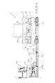
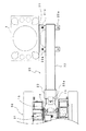
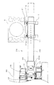
図1および図2は請求項1の発明の実施の形態を示すもので、図1は平面図で、図2は側面図である。図1において、1はチュービング装置、10は回転反力取り装置、30は作業機である。
【0020】
チュービング装置1は、図2に示すように、ベースフレーム3の四隅に設けた昇降シリンダ4に連結された昇降フレーム2を備え、この昇降フレーム2にはケーシングチューブが挿通されるテーパ孔を有する回転フレーム8が回転可能に支持され、上部フレーム7に連結されたチャックシリンダ6によってケーシングチューブとテーパ孔との間に楔部材を挿入して、回転フレーム8とケーシングチューブとを締結するように構成されている。
【0021】
そして、ケーシングチューブを回転フレーム8に把持した状態で昇降フレーム2上に配置されたモータにより回転フレーム8を回転駆動させるとともに昇降シリンダ4を下降させることによりケーシングチューブを地中に押し込んでいる。作業機30は、ケーシングチューブ内の土砂を排出するためのもので、上記図8(a)で示した移動式クレーンにハンマグラブを装備した周知のハンマグラブ機である。
【0022】
回転反力取り装置10はベースフレーム3の一側面に取り付けられたブラケット11と、ビーム12と、作業機30のトラックフレーム31に固設された取付金具14と、ビーム12と取付金具14を連結する取付部材13とから構成されている。
【0023】
ブラケット11はベースフレーム3に固設された取付部材21に2本のピン11aによって連結され、ビーム12が挿通可能な角筒状に構成されている。したがって、ビーム12はその長手方向をブラケット11に任意な位置に置くことができる。なお、ビーム12の位置が確定したときは固定ピン17によってビーム12をブラケット11に固定するようにしてもよい。
【0024】
ビーム12は矩形の角筒状で、作業機30のトラックフレーム31に連結される側には取付部材13が固設されており、取付部材13には金具13aが固設されている。
トラックフレーム31にはピン穴を備えた二股状の取付金具14が2本のピン16で連結されており、上記取付部材13の金具13aと垂直方向のピン15によって連結されている。なお、取付金具14はビーム12より高い位置に取り付けられているので、取付部材13の金具13aは取付金具14とほぼ同じ高さ位置に付設されている。また、ビーム12の下端にはビーム12の高さを調整するための調整ボルト12aが付設されている。
【0025】
回転反力取り装置10を取り付けるときは、ビーム12の一端側をチュービング装置1のベースフレーム3に取り付けられたブラケット11にクレーンで吊持しながら挿通する。
そして、ビーム12を作業機30(ハンマグラブ)がケーシングチューブ内の土砂の排出作業に最適な位置になるように位置させ、作業機30を走行させて、トラックフレーム31の取付金具14と取付部材13を係合させてピン15で連結する。
【0026】
なお、図示してないが、チュービング装置1の押込みに対する反力受けとして、チュービング装置1に突設した腕にウエイトを載置するが、回転反力取り装置10のブラケット11を腕と兼用し、この上にウエイトを載置してもよい。
チュービング装置1を作動させると、ケーシングチューブの回転反力がベースフレーム3に作用するが、この回転反力はブラケット11およびビーム12を介して作業機30によって受けられる。
【0027】
作業機30をアースドリルに変更する場合は、ビーム12を作業機30の走行によりブラケット11へ押込んでビーム12がアースドリルでケーシングチューブ内の土砂の排出作業に最適な位置に位置させる。なお、ビーム12を固定ピン17でブラケット11に固定している場合は固定ピン17を外してから行う。
【0028】
そして、ピン15を外して作業機30(アースドリル)に入れ替えて、取付金具14と取付部材13の金具13aとをピン15で連結する。
あるいは、作業機30(ハンマグラブ)の作業位置でピン15を外して作業機30(アースドリル)と入れ替え、取付金具14と金具13aとをピン15で連結してから作業機30(アースドリル)を作業に最適な位置まで走行させてもよい。
【0029】
このときの状態は、図1および図2において取付部材13は点線で示す位置となり、ビーム12はその分ブラケット11の後方へ突出する。
このように、作業機30の位置が大幅に変更になっても、簡便に回転反力取り装置10を取り付けることができる。
【0030】
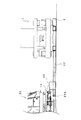
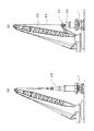
次に、請求項2の発明の実施の形態を図3および図4に基づいて説明する。
なお、図において、上記請求項1の発明で説明したものと同じものは同じ符号を付して、説明は省略する。
回転反力取り装置20はベースフレーム3の一側面に取り付けられた取付部材21と、スライドブラケット23を備えたビーム22と、作業機30のトラックフレーム31に固設された取付金具14とから構成されている。
【0031】
ビーム22は矩形の角筒状で、ベースフレーム3に取り付けた取付部材21に連結するための取付金具22aが左右勝手になっても取り付けられるように左右に2個ずつ突設され、ピン21aで連結されている。そして、作業機30のトラックフレーム31に連結される他端側にはビーム22を外嵌してスライド可能なスライドブラケット23が設けられている。
【0032】
スライドブラケット23には作業機30のトラックフレーム31に固設された取付金具14と連結するための金具23aが固設されており、ピン15で連結される。なお、金具23aはトラックフレーム31に固設された取付金具14とほぼ同じ高さの位置に固設されている。
【0033】
また、ビーム22の先端には金具23a高さを取付金具14と位置合わせするための高さ調整ボルト22aが設けられている。
トラックフレーム31にはピン穴を備えた二股状の取付金具14が2本のピン16で連結されており、垂直方向のピン15によってビーム22に外嵌されたスライドブラケット23の金具23aと連結されている。
【0034】
回転反力取り装置20を取り付けるときは、まず、ビーム22の取付金具22aをチュービング装置1に取り付けられた取付部材21に挿入してピン21aで連結する。そして、スライドブラケット23を作業機30がケーシングチューブ内の土砂の排出作業に最適な位置に位置させ、作業機30をブラケット23の位置まで走行させて、金具23aとトラックフレーム31の取付金具14と位置合わせしてピン15で連結する。あるいは、金具23aとトラックフレーム31の取付金具14とをピン15で連結してから、作業機を最適作業位置まで走行させてもよい。
【0035】
作業機30をアースドリルに変更する場合は、作業機30(ハンマグラブ)を走行させてスライドブラケット23をチュービング装置1側に寄せて作業機30(アースドリル)がケーシングチューブ内の土砂の排出作業に最適な位置に位置させてからピン15を外して作業機30(アースドリル)と入れ替え、取付金具14と金具23aとをピン15で連結する。
【0036】
あるいは、作業機30(ハンマグラブ)の作業位置でピン15を外して作業機30(アースドリル)と入れ替え、取付金具14と金具23aとをピン15で連結してから作業機30(アースドリル)を作業に最適な位置まで走行させてもよい。
【0037】
スライドブラケット23をチュービング装置1側に寄せた場合は、ビーム22の作業機30側は、図5において点線で示すように、トラックフレームの下部に侵入する。
図6は、請求項2の発明の別の実施の形態を示すもので、チュービング装置1の端面に取り付けられた取付部材25にビーム26をチュービング装置1と直角方向に位置させてビーム26に固設した金具26aとピンで連結している。
【0038】
ビーム26の他端側の作業機30との連結は図3および図4と同じである。
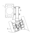
次に、請求項3の発明の実施の形態を図7に基づいて説明する。
なお、図において、上記請求項1および請求項2の発明で説明したものと同じものは同じ符号を付して、説明を省略する。
【0039】
回転反力取り装置28はベースフレーム3の一側面に取り付けられたブラケット11と、スライドブラケット23を備えたビーム29と、作業機30のトラックフレーム31に固設された取付金具14とから構成されている。
ビーム29は矩形の角筒状で、作業機30のトラックフレーム31に連結される他端側にはビーム29を外嵌してスライド可能なスライドブラケット23が設けられている。
【0040】
スライドブラケット23には作業機30のトラックフレーム31に固設された取付金具14と連結するための金具23aが固設されており、ピン15で連結される。なお、ブラケット11とビーム29とはピン17で連結でき、スライドブラケット23とビーム29とは図示してないがピンで連結可能となっている。
【0041】
回転反力取り装置28を取り付けるときは、まず、ビーム29の一端側をチュービング装置1のベースフレーム3に取り付けられたブラケット11に挿通する。
そして、作業機30(ハンマグラブ)がケーシングチューブ内の土砂の排出作業に最適な位置になるように、ビーム29を作業機30側へ引き出すか、またはスライドブラケット23を作業機30側へ寄せて位置させ、金具23aとトラックフレーム31の取付金具14とを位置合わせしてピン15で連結する。
【0042】
作業機30をアースドリルへ変更する場合は、ピン15を外して作業機30(アースドリル)に入れ替え、ピン15を連結してからスライドブラケット23をチュービング装置1側に寄せるか、ビーム29の一端側をブラケット11内を後方へスライドさせる。この場合、移動させない側はピンで固定する。
【0043】
なお、上記実施の形態では、作業機30をビーム12,26,29の軸線に平行に位置させ、作業機30の走行によりビーム12,26,29またはスライドブラケット23を移動させて取り付けるもので説明したが、ビーム12,26,29またはスライドブラケット23を吊り上げなどで移動させる場合は、図5に示したように、作業機30をビーム12,26,29の軸線に対して傾斜させて配置することは可能である。
【0044】
【発明の効果】
以上説明したように、請求項1の発明のチュービング装置の回転反力取り装置は、チュービング装置のベースフレームの一端面にビームを長手方向にスライド可能に支持するようにしたので、作業機をケーシングチューブ内の土砂を排出する最適な位置に置くことができ、ハンマグラブの場合とアースドリルの場合のようにチュービング装置と作業機との距離が大きく変化しても、簡便に取り付けることができる。また、請求項2の発明は、ビームのトラックフレームとの取付をビームを外嵌してスライド可能なスライドブラケットを介して行うようにしたので、請求項1の発明と同様の効果が得られる。さらに、請求項3の発明はチュービング装置側および作業機側のいずれもビームの取付位置が任意であるので、狭い現場や壁際での作業など種々の作業現場に対して回転反力取り装置の取付が簡便にできる。
さらに、請求項1〜3のいずれの発明においても、ビームがブラケットを貫通するようにしてブラケットにスライド可能に連結されているので、ビームのスライド量、つまりチュービング装置と作業機との距離が変化してもビームとブラケットとの重なり量は変化しない。
したがって、請求項1〜3のいずれの発明においても、「最も縮小させた場合でもかなりの長さとなり、アースドリルがチュービング装置に近寄りきれない」といった問題を解決することができる。
【図面の簡単な説明】
【図1】請求項1の発明のチュービング装置の回転反力取り装置の実施の形態を示す平面図である。
【図2】同 側面図である。
【図3】請求項2の発明のチュービング装置の回転反力取り装置の実施の形態を示す平面図である。
【図4】同 側面図である。
【図5】同 ビームと作業機(アースドリル)との連結状態を示す平面図である。
【図6】請求項2の発明のチュービング装置の回転反力取り装置の別の実施の形態を示す平面図である。
【図7】請求項3の発明のチュービング装置の回転反力取り装置の実施の形態を示す平面図である。
【図8】作業機の全体を示すもので、(a)は移動式クレーンにハンマグラブを搭載した側面図、(b)はアースドリルである。
【符号の説明】
1…チュービング装置 2…昇降フレーム
3…ベースフレーム 4…昇降シリンダ
6…チャックシリンダ 7…上部フレーム
8…回転フレーム
10…回転反力取り装置 11…ブラケット
11a…ピン 12…ビーム
12a…高さ調整ボルト 13…取付部材
13a…金具 14…取付金具
15,16…ピン 17…固定ピン
20…回転反力取り装置 21…取付部材
21a…ピン 22…ビーム
22a…高さ調整ボルト 23…スライドブラケット
23a…金具 25…取付部材
26…ビーム 26a…金具
28…回転反力取り装置 29…ビーム
30…作業機 31…トラックフレーム
32…ブーム 33…ハンマグラブ
34…ケリーバ 35…回転駆動装置
36…バケット[0001]
BACKGROUND OF THE INVENTION
The present invention relates to a device that takes a rotational reaction force of a tubing device that is pushed in while rotating a casing tube into the ground.
[0002]
[Prior art]
As the construction of cast-in-place piles, the tubing with a drilling blade at the lower end of the casing is pushed into the ground while rotating or swinging with a tubing device, and the earth and sand in the casing tube is discharged by a mobile crane equipped with a hammer magnet. An all-casing method is known in which a pile is built inside and a casing tube is collected.
[0003]
Conventionally, various devices have been put to practical use as a device for taking the reaction force of the rotational drive of the tubing device. In the operation of the tubing device, a working machine for discharging earth and sand in the casing tube is shown in FIG. A mobile crane equipped with such a
[0004]
As shown in Japanese Utility Model Laid-Open No. 1-105645, one end of the beam is swingably attached to the base frame of the casing tube, and the other end of the beam is brought into contact with the end surface of the crawler belt or the crawler surface of the work machine. As shown in Japanese Utility Model Application No. 3-52262 filed earlier by the applicant, one end of the beam is detachably attached to the base frame of the tubing device, and the other end is attached to the track frame of the work machine. Some are connected with pins.
[0005]
[Problems to be solved by the invention]
However, since it is necessary to perform the work machine at a position suitable for discharging the earth and sand in the casing tube, it may be difficult to install the rotation reaction force removing device.
For example, in a normally used work with a hammer maglab, the hammer maglab is dropped in order to bite it into the earth and sand, and since the boom is raised at the time of dropping, the angle of the crane boom cannot be increased. Therefore, the body of the Hanmaglab is working considerably away from the tubing device.
[0006]
In addition, since the amount of soil discharged per hammermaglab is small, the earth and sand in the casing tube is discharged by a ground drill as shown in FIG. 8 (b) on soft ground. Since the angle of the
[0007]
Some rotary reaction force removal devices have a double beam structure so that they can be installed by expanding and contracting even if the distance between the tubing device and the work equipment is different, but in the case of a hammaglab and an earth drill, the distance difference is 2 m. Because of this, double-structured beams are large and heavy and difficult to handle, and even when extended to the maximum, it is necessary for the beams to overlap to some extent, so the beam is most reduced. Even if it is, it will be quite long and the earth drill will not be close to the tubing device. Therefore, in general, a rotational reaction force removing device corresponding to each of the hammer magnet and the earth drill is separately prepared.
[0008]
However, in actual work, hard ground layers and soft ground layers are often intricate, and soil removal work is performed using a hammaglab and an earth drill according to the ground. Since it is necessary to replace the take-off device, if it takes a lot of time, the meaning of changing the work machine is lost.
[0009]
Accordingly, an object of the present invention is to provide a rotational reaction force removing device for a tubing device that is easy to handle and can be used even when the distance between the working machine and the tubing device changes greatly.
[0010]
[Means for Solving the Problems]
The rotational reaction force removing device for a tubing device according to the present invention uses a working machine for discharging earth and sand in a casing tube as a reaction force support. The tubing device can be applied to either a rotary type or a swing type.
[0011]
The work machines include those that are equipped with working tools such as hammaglabs and down-the-hole hammers on a crawler crane, as well as those equipped with hammaglabs on earth drills and earth drills.
According to the first aspect of the present invention, in the rotational reaction force removing device of the tubing device that is pushed into the ground while rotating or swinging the casing tube, the beam is supported on one end surface of the base frame of the tubing device so as to be slidable in the longitudinal direction. A bracket is provided so that the beam penetrates the bracket, one end of the beam is supported by the bracket, and the other end of the beam is detachably connected to a track frame of a work machine that discharges earth and sand in the casing tube. It is characterized by that.
[0012]
The bracket is not particularly limited as long as it can support the beam so as to be slidable. It is desirable that the bracket has a cylindrical shape or a U-shaped cross section so that the beam can be inserted. The bracket need not be attached to the entire length of one side of the tubing device.
Also, it is desirable that the upper surface of the bracket be flat so that a weight for taking a reaction force against the pushing of the tubing device can be placed thereon.
[0013]
Further, the shape of the beam is not particularly limited, but it is desirable that the one end side supported by the tubing device slides, so that it is a rectangular tube having the same cross section.
The beam and the work machine may be connected to each other as long as they can be attached and detached. In the case of pin connection, if the vertical pin is used, the angle of the working machine can be arbitrarily set with respect to the beam, which is effective in a narrow construction site.
[0014]
In the present invention, when the distance between the work implement and the tubing device is short, the beam is supported in a state of projecting rearward through the bracket. In addition, since the rotational reaction force becomes large in hard ground, it is desirable to connect the beam to the bracket.
According to a second aspect of the present invention, in the rotational reaction force removing device for a tubing device that is pushed into the ground while rotating or swinging the casing tube, one end side of the beam is connected to one end surface of the base frame of the tubing device, The slide bracket is slidable so that the beam penetrates on the other end side, and the slide bracket is detachably connected to a track frame of a working machine for discharging earth and sand in the casing tube.
[0015]
The difference from the invention of
[0016]
Attachment of the beam to the tubing device is optional. For example, the beam may be connected with a pin along one end surface of the tubing device, or a bracket may be provided on one end surface of the tubing device so that the beam is perpendicular to the one end surface of the tubing device. .
[0017]
According to a third aspect of the present invention, in the rotational reaction force removing device of the tubing device that is pushed into the ground while rotating or swinging the casing tube, the beam is supported on one end surface of the base frame of the tubing device so as to be slidable in the longitudinal direction. the bracket is provided, the beam so as to penetrate the bracket is supported by a bracket one end of the beam, further, to the other end of the beam providing a slidable slide bracket fitted to the beam, the slide bracket Is detachably connected to a truck frame of a work machine for discharging earth and sand in the casing tube.
[0018]
The difference between the invention of
[0019]
DETAILED DESCRIPTION OF THE INVENTION
Embodiments of the present invention will be described below with reference to the drawings.
1 and 2 show an embodiment of the invention of
[0020]
As shown in FIG. 2, the
[0021]
The casing tube is pushed into the ground by rotating the rotating frame 8 and lowering the
[0022]
The rotation reaction
[0023]
The
[0024]
The
A bifurcated mounting
[0025]
When attaching the rotational reaction
Then, the
[0026]
Although not shown, a weight is placed on the arm protruding from the
When the
[0027]
When the working
[0028]
Then, the
Alternatively, the
[0029]
In this state, the
Thus, even if the position of the
[0030]
Next, an embodiment of the invention of
In the figure, the same components as those described in the first aspect of the present invention are denoted by the same reference numerals, and the description thereof is omitted.
The rotational reaction
[0031]
The
[0032]
A metal fitting 23 a is connected to the
[0033]
Further, a height adjusting bolt 22 a for aligning the height of the metal fitting 23 a with the mounting
A bifurcated mounting
[0034]
When attaching the rotational reaction
[0035]
When the
[0036]
Alternatively, the
[0037]
When the
FIG. 6 shows another embodiment of the invention of
[0038]
The connection with the
Next, an embodiment of the invention of
In the figure, the same components as those described in the first and second aspects of the present invention are denoted by the same reference numerals, and the description thereof is omitted.
[0039]
The rotation reaction
The
[0040]
A metal fitting 23 a is connected to the
[0041]
When the rotation reaction
Then, the
[0042]
When the
[0043]
In the above embodiment, the working
[0044]
【The invention's effect】
As described above, in the rotation reaction force removing device for the tubing device according to the first aspect of the present invention, the beam is supported by the one end surface of the base frame of the tubing device so as to be slidable in the longitudinal direction. It can be placed at an optimum position for discharging the earth and sand in the tube, and can be easily attached even if the distance between the tubing device and the working machine is greatly changed as in the case of a hammaglab and an earth drill. In the invention of
Further, in any of the first to third aspects of the invention, since the beam penetrates the bracket and is slidably connected to the bracket, the slide amount of the beam, that is, the distance between the tubing device and the work machine changes. Even so, the amount of overlap between the beam and the bracket does not change.
Accordingly, in any of the first to third aspects of the invention, it is possible to solve the problem that “the length of the ground drill is considerably long even when it is most reduced, and the earth drill cannot approach the tubing device”.
[Brief description of the drawings]
1 is a plan view showing an embodiment of a rotational reaction force removing device for a tubing device according to a first aspect of the present invention;
FIG. 2 is a side view of the same.
FIG. 3 is a plan view showing an embodiment of a rotational reaction force removing device for a tubing device according to a second aspect of the present invention;
FIG. 4 is a side view of the same.
FIG. 5 is a plan view showing a connection state between the beam and a work machine (earth drill).
FIG. 6 is a plan view showing another embodiment of the rotational reaction force removing device for the tubing device according to the second aspect of the present invention;
FIG. 7 is a plan view showing an embodiment of a rotational reaction force removing device for a tubing device according to a third aspect of the invention;
FIGS. 8A and 8B show an entire working machine, in which FIG. 8A is a side view in which a hammer crane is mounted on a mobile crane, and FIG. 8B is an earth drill.
[Explanation of symbols]
DESCRIPTION OF
Claims (3)
チュービング装置のベースフレームの一端面にビームを長手方向にスライド可能に支持するブラケットを設け、
前記ビームが前記ブラケットを貫通するようにして前記ビームの一端側を前記ブラケットで支持し、
さらに、前記ビームの他端を前記ケーシングチューブ内の土砂を排出する作業機のトラックフレームに脱着可能に連結したことを特徴とするチュービング装置の回転反力取り装置。In the rotational reaction force removing device of the tubing device that pushes into the ground while rotating or swinging the casing tube,
A bracket for slidably supporting the beam in the longitudinal direction is provided on one end surface of the base frame of the tubing device,
One end of said beam is supported by the bracket so as the beam penetrates the bracket,
Further, rotational reaction force eliminating device tubing device characterized by the other end of the beam connected detachably to the track frame of the working machine for discharging the earth and sand in the casing tube.
ビームの一端側を前記チュービング装置のベースフレームの一端面に連結し、
前記ビームの他端側に前記ビームが貫通するようにスライド可能なスライドブラケットを設け、
さらに、前記スライドブラケットをケーシングチューブ内の土砂を排出する作業機のトラックフレームに脱着可能に連結したことを特徴とするチュービング装置の回転反力取り装置。In the rotational reaction force removing device of the tubing device that pushes into the ground while rotating or swinging the casing tube,
Connecting one end of the beam on one end face of the base frame of the tubing system,
A slidable slide bracket provided so that the beam penetrates the other end of the beam,
Further, the rotation reaction force removing device for a tubing device , wherein the slide bracket is detachably connected to a track frame of a working machine for discharging earth and sand in a casing tube.
前記チュービング装置のベースフレームの一端面にビームを長手方向にスライド可能に支持するブラケットを設け、
前記ビームが前記ブラケットを貫通するようにして前記ビームの一端側を前記ブラケットで支持し、
さらに、ビームの他端側にはビームを外嵌してスライド可能なスライドブラケットを設け、該スライドブラケットをケーシングチューブ内の土砂を排出する作業機のトラックフレームに脱着可能に連結したことを特徴とするチュービング装置の回転反力取り装置。In the rotational reaction force removing device of the tubing device that pushes into the ground while rotating or swinging the casing tube,
A bracket for supporting the beam on one end face of the base frame slidably in the longitudinal direction of the tubing apparatus is provided,
One end of said beam is supported by the bracket so as the beam penetrates the bracket,
Furthermore, a slide bracket is provided on the other end side of the beam so that the beam can be fitted and slidable. Rotating reaction force removing device for tubing device.
Priority Applications (1)
| Application Number | Priority Date | Filing Date | Title |
|---|---|---|---|
| JP2001245276A JP3754331B2 (en) | 2001-08-13 | 2001-08-13 | Rotating reaction force removing device for tubing device |
Applications Claiming Priority (1)
| Application Number | Priority Date | Filing Date | Title |
|---|---|---|---|
| JP2001245276A JP3754331B2 (en) | 2001-08-13 | 2001-08-13 | Rotating reaction force removing device for tubing device |
Publications (2)
| Publication Number | Publication Date |
|---|---|
| JP2003055968A JP2003055968A (en) | 2003-02-26 |
| JP3754331B2 true JP3754331B2 (en) | 2006-03-08 |
Family
ID=19075062
Family Applications (1)
| Application Number | Title | Priority Date | Filing Date |
|---|---|---|---|
| JP2001245276A Expired - Fee Related JP3754331B2 (en) | 2001-08-13 | 2001-08-13 | Rotating reaction force removing device for tubing device |
Country Status (1)
| Country | Link |
|---|---|
| JP (1) | JP3754331B2 (en) |
Families Citing this family (2)
| Publication number | Priority date | Publication date | Assignee | Title |
|---|---|---|---|---|
| JP2014214574A (en) * | 2013-04-30 | 2014-11-17 | 菱建基礎株式会社 | Reaction force bar |
| JP6156918B2 (en) * | 2013-04-30 | 2017-07-05 | 菱建基礎株式会社 | Reaction force bar |
-
2001
- 2001-08-13 JP JP2001245276A patent/JP3754331B2/en not_active Expired - Fee Related
Also Published As
| Publication number | Publication date |
|---|---|
| JP2003055968A (en) | 2003-02-26 |
Similar Documents
| Publication | Publication Date | Title |
|---|---|---|
| CA2668291C (en) | System for mounting a pile driver | |
| EP0649973A3 (en) | Hydraulic excavator for shield tunneling machine. | |
| JP2888505B2 (en) | Work trolley | |
| JP3754331B2 (en) | Rotating reaction force removing device for tubing device | |
| AU2002214153C1 (en) | Trenching method and apparatus | |
| JP2003269064A (en) | Boring machine | |
| JP3544971B2 (en) | Drilling machine | |
| JP4098906B2 (en) | Pile driver | |
| JP3844166B2 (en) | Slope drilling machine and slope drilling method | |
| JP3450116B2 (en) | Drilling equipment for excavators | |
| JP4048141B2 (en) | Foundation pile construction equipment | |
| JP2002081065A (en) | Rotary reaction removing device for tubing device | |
| JP2922102B2 (en) | Slope drilling equipment | |
| JPH04169696A (en) | Support device for wall surface digging chain cutter | |
| JP2024517205A (en) | Earthmoving Machinery | |
| JPH04119847U (en) | Power swivel | |
| JP2741640B2 (en) | Suspended earth auger pile driver | |
| JP3129537B2 (en) | Vertical hole drilling rig | |
| JP2005096134A (en) | Core drill apparatus | |
| JP2002201887A (en) | Excavator | |
| JPH0235912Y2 (en) | ||
| KR200271533Y1 (en) | An excavator head for useing back hoe | |
| JP3229488B2 (en) | Pile driver leader | |
| JPS61146918A (en) | Large pile driving machine | |
| JP2000087695A (en) | Tunnel boring device |
Legal Events
| Date | Code | Title | Description |
|---|---|---|---|
| A131 | Notification of reasons for refusal |
Free format text: JAPANESE INTERMEDIATE CODE: A131 Effective date: 20050607 |
|
| A521 | Written amendment |
Free format text: JAPANESE INTERMEDIATE CODE: A523 Effective date: 20050711 |
|
| A131 | Notification of reasons for refusal |
Free format text: JAPANESE INTERMEDIATE CODE: A131 Effective date: 20050802 |
|
| TRDD | Decision of grant or rejection written | ||
| A01 | Written decision to grant a patent or to grant a registration (utility model) |
Free format text: JAPANESE INTERMEDIATE CODE: A01 Effective date: 20051122 |
|
| A61 | First payment of annual fees (during grant procedure) |
Free format text: JAPANESE INTERMEDIATE CODE: A61 Effective date: 20051215 |
|
| R150 | Certificate of patent or registration of utility model |
Free format text: JAPANESE INTERMEDIATE CODE: R150 |
|
| FPAY | Renewal fee payment (event date is renewal date of database) |
Free format text: PAYMENT UNTIL: 20081222 Year of fee payment: 3 |
|
| FPAY | Renewal fee payment (event date is renewal date of database) |
Free format text: PAYMENT UNTIL: 20091222 Year of fee payment: 4 |
|
| FPAY | Renewal fee payment (event date is renewal date of database) |
Free format text: PAYMENT UNTIL: 20091222 Year of fee payment: 4 |
|
| FPAY | Renewal fee payment (event date is renewal date of database) |
Free format text: PAYMENT UNTIL: 20101222 Year of fee payment: 5 |
|
| FPAY | Renewal fee payment (event date is renewal date of database) |
Free format text: PAYMENT UNTIL: 20111222 Year of fee payment: 6 |
|
| FPAY | Renewal fee payment (event date is renewal date of database) |
Free format text: PAYMENT UNTIL: 20111222 Year of fee payment: 6 |
|
| FPAY | Renewal fee payment (event date is renewal date of database) |
Free format text: PAYMENT UNTIL: 20121222 Year of fee payment: 7 |
|
| FPAY | Renewal fee payment (event date is renewal date of database) |
Free format text: PAYMENT UNTIL: 20121222 Year of fee payment: 7 |
|
| FPAY | Renewal fee payment (event date is renewal date of database) |
Free format text: PAYMENT UNTIL: 20131222 Year of fee payment: 8 |
|
| R250 | Receipt of annual fees |
Free format text: JAPANESE INTERMEDIATE CODE: R250 |
|
| R250 | Receipt of annual fees |
Free format text: JAPANESE INTERMEDIATE CODE: R250 |
|
| LAPS | Cancellation because of no payment of annual fees |