JP3750397B2 - Capacity control valve for variable capacity compressor - Google Patents
Capacity control valve for variable capacity compressor Download PDFInfo
- Publication number
- JP3750397B2 JP3750397B2 JP05249499A JP5249499A JP3750397B2 JP 3750397 B2 JP3750397 B2 JP 3750397B2 JP 05249499 A JP05249499 A JP 05249499A JP 5249499 A JP5249499 A JP 5249499A JP 3750397 B2 JP3750397 B2 JP 3750397B2
- Authority
- JP
- Japan
- Prior art keywords
- valve
- valve body
- chamber
- pressure
- valve seat
- Prior art date
- Legal status (The legal status is an assumption and is not a legal conclusion. Google has not performed a legal analysis and makes no representation as to the accuracy of the status listed.)
- Expired - Fee Related
Links
- 230000007423 decrease Effects 0.000 claims description 15
- 238000000605 extraction Methods 0.000 claims description 14
- 238000006073 displacement reaction Methods 0.000 claims description 13
- 230000005540 biological transmission Effects 0.000 claims description 10
- 230000008859 change Effects 0.000 claims description 8
- 230000002093 peripheral effect Effects 0.000 description 15
- 239000003507 refrigerant Substances 0.000 description 14
- 238000001816 cooling Methods 0.000 description 9
- 230000004043 responsiveness Effects 0.000 description 9
- 230000007246 mechanism Effects 0.000 description 7
- 230000008602 contraction Effects 0.000 description 3
- 230000008878 coupling Effects 0.000 description 3
- 238000010168 coupling process Methods 0.000 description 3
- 238000005859 coupling reaction Methods 0.000 description 3
- 238000007789 sealing Methods 0.000 description 3
- 238000011144 upstream manufacturing Methods 0.000 description 3
- 230000000903 blocking effect Effects 0.000 description 2
- 230000006835 compression Effects 0.000 description 2
- 238000007906 compression Methods 0.000 description 2
- 238000010586 diagram Methods 0.000 description 2
- 230000000694 effects Effects 0.000 description 2
- 239000012530 fluid Substances 0.000 description 2
- 238000005192 partition Methods 0.000 description 2
- 230000001052 transient effect Effects 0.000 description 2
- 230000009471 action Effects 0.000 description 1
- 239000000463 material Substances 0.000 description 1
- 230000004044 response Effects 0.000 description 1
- 230000003313 weakening effect Effects 0.000 description 1
Images


Classifications
-
- F—MECHANICAL ENGINEERING; LIGHTING; HEATING; WEAPONS; BLASTING
- F04—POSITIVE - DISPLACEMENT MACHINES FOR LIQUIDS; PUMPS FOR LIQUIDS OR ELASTIC FLUIDS
- F04B—POSITIVE-DISPLACEMENT MACHINES FOR LIQUIDS; PUMPS
- F04B27/00—Multi-cylinder pumps specially adapted for elastic fluids and characterised by number or arrangement of cylinders
- F04B27/08—Multi-cylinder pumps specially adapted for elastic fluids and characterised by number or arrangement of cylinders having cylinders coaxial with, or parallel or inclined to, main shaft axis
- F04B27/14—Control
- F04B27/16—Control of pumps with stationary cylinders
- F04B27/18—Control of pumps with stationary cylinders by varying the relative positions of a swash plate and a cylinder block
- F04B27/1804—Controlled by crankcase pressure
- F04B2027/1809—Controlled pressure
- F04B2027/1813—Crankcase pressure
-
- F—MECHANICAL ENGINEERING; LIGHTING; HEATING; WEAPONS; BLASTING
- F04—POSITIVE - DISPLACEMENT MACHINES FOR LIQUIDS; PUMPS FOR LIQUIDS OR ELASTIC FLUIDS
- F04B—POSITIVE-DISPLACEMENT MACHINES FOR LIQUIDS; PUMPS
- F04B27/00—Multi-cylinder pumps specially adapted for elastic fluids and characterised by number or arrangement of cylinders
- F04B27/08—Multi-cylinder pumps specially adapted for elastic fluids and characterised by number or arrangement of cylinders having cylinders coaxial with, or parallel or inclined to, main shaft axis
- F04B27/14—Control
- F04B27/16—Control of pumps with stationary cylinders
- F04B27/18—Control of pumps with stationary cylinders by varying the relative positions of a swash plate and a cylinder block
- F04B27/1804—Controlled by crankcase pressure
- F04B2027/1822—Valve-controlled fluid connection
- F04B2027/1827—Valve-controlled fluid connection between crankcase and discharge chamber
-
- F—MECHANICAL ENGINEERING; LIGHTING; HEATING; WEAPONS; BLASTING
- F04—POSITIVE - DISPLACEMENT MACHINES FOR LIQUIDS; PUMPS FOR LIQUIDS OR ELASTIC FLUIDS
- F04B—POSITIVE-DISPLACEMENT MACHINES FOR LIQUIDS; PUMPS
- F04B27/00—Multi-cylinder pumps specially adapted for elastic fluids and characterised by number or arrangement of cylinders
- F04B27/08—Multi-cylinder pumps specially adapted for elastic fluids and characterised by number or arrangement of cylinders having cylinders coaxial with, or parallel or inclined to, main shaft axis
- F04B27/14—Control
- F04B27/16—Control of pumps with stationary cylinders
- F04B27/18—Control of pumps with stationary cylinders by varying the relative positions of a swash plate and a cylinder block
- F04B27/1804—Controlled by crankcase pressure
- F04B2027/1822—Valve-controlled fluid connection
- F04B2027/1831—Valve-controlled fluid connection between crankcase and suction chamber
-
- F—MECHANICAL ENGINEERING; LIGHTING; HEATING; WEAPONS; BLASTING
- F04—POSITIVE - DISPLACEMENT MACHINES FOR LIQUIDS; PUMPS FOR LIQUIDS OR ELASTIC FLUIDS
- F04B—POSITIVE-DISPLACEMENT MACHINES FOR LIQUIDS; PUMPS
- F04B27/00—Multi-cylinder pumps specially adapted for elastic fluids and characterised by number or arrangement of cylinders
- F04B27/08—Multi-cylinder pumps specially adapted for elastic fluids and characterised by number or arrangement of cylinders having cylinders coaxial with, or parallel or inclined to, main shaft axis
- F04B27/14—Control
- F04B27/16—Control of pumps with stationary cylinders
- F04B27/18—Control of pumps with stationary cylinders by varying the relative positions of a swash plate and a cylinder block
- F04B27/1804—Controlled by crankcase pressure
- F04B2027/184—Valve controlling parameter
- F04B2027/1854—External parameters
-
- F—MECHANICAL ENGINEERING; LIGHTING; HEATING; WEAPONS; BLASTING
- F04—POSITIVE - DISPLACEMENT MACHINES FOR LIQUIDS; PUMPS FOR LIQUIDS OR ELASTIC FLUIDS
- F04B—POSITIVE-DISPLACEMENT MACHINES FOR LIQUIDS; PUMPS
- F04B27/00—Multi-cylinder pumps specially adapted for elastic fluids and characterised by number or arrangement of cylinders
- F04B27/08—Multi-cylinder pumps specially adapted for elastic fluids and characterised by number or arrangement of cylinders having cylinders coaxial with, or parallel or inclined to, main shaft axis
- F04B27/14—Control
- F04B27/16—Control of pumps with stationary cylinders
- F04B27/18—Control of pumps with stationary cylinders by varying the relative positions of a swash plate and a cylinder block
- F04B27/1804—Controlled by crankcase pressure
- F04B2027/184—Valve controlling parameter
- F04B2027/1859—Suction pressure
Landscapes
- Engineering & Computer Science (AREA)
- Mechanical Engineering (AREA)
- General Engineering & Computer Science (AREA)
- Compressors, Vaccum Pumps And Other Relevant Systems (AREA)
- Control Of Positive-Displacement Pumps (AREA)
- Magnetically Actuated Valves (AREA)
Description
【0001】
【発明の属する技術分野】
本発明は、例えば、車両空調装置に用いられる可変容量型圧縮機用の容量制御弁に関する。
【0002】
【従来の技術】
この種の可変容量型圧縮機(以下、単に圧縮機と呼ぶ)としては、例えば、吸入圧領域と斜板を収容するクランク室とを連通する抽気通路と、クランク室と吐出圧領域とを連通する給気通路とを備え、クランク室の圧力を調節することにより斜板の傾斜角を変更して、吐出容量を調節する構成のものが知られている。クランク室の圧力調節は、容量制御弁によって抽気通路及び給気通路を開閉することで、クランク室から吸入圧領域への冷媒ガスの排出量、及び吐出圧領域からクランク室への高圧冷媒ガスの供給量が変更されて行われている。
【0003】
この従来の圧縮機用の容量制御弁としては、例えば、特開平5−99136号公報において開示されたものが存在する。すなわち、図6及び図7に示すように、第1弁室101 は、第1弁孔102 及び抽気通路201 の上流側を介してクランク室202 に連通されるとともに、抽気通路201 の下流側を介して吸入圧領域203 に連通されている。第1弁体103 は第1弁孔102 を開閉する。第2弁室104 は、給気通路204 の上流側を介して吐出圧領域205 に連通されるとともに、第2弁孔105 及び給気通路204 の下流側を介してクランク室202 に連通されている。第2弁体106 は第2弁孔105 を開閉する。第1バネ107 は、第2弁孔105 を閉塞する方向に第2弁体106 を付勢する。
【0004】
第1ロッド108 は、第1弁体103 に摺動可能に内挿されている。第2ロッド109 は、下端部が第1ロッド108 に固定されるとともに、上端部が第2弁孔105 に挿入されている。第2バネ111 は、第1ロッド108 に固定された止め輪110 と第1弁体103 との間に介在され、第1弁体103 を第1ロッド108 のストッパ部108a(図6において拡大円中に示す)に常時当接させるように付勢する。第3バネ112 は、第1ロッド108 、第2ロッド109 、第1弁体103 、止め輪110 及び第2バネ111 が結合された結合系を、ダイヤフラム113 に常時押し付ける。ダイヤフラム113 は、第1弁室101 に連通された感圧室114 の吸入圧力と大気圧とのバランスで上下に変位される。第1弁体103 はダイヤフラム114 の上下変位に応じて動作し、第1弁孔102 を開閉する。
【0005】
例えば、前記感圧室114 の吸入圧力が設定値(設定吸入圧力)より上昇すると、ダイヤフラム113 が下方に変位して第1弁体103 が第1弁孔102 を開放する方向に移動される。従って、クランク室202 から吸入圧領域203 への冷媒ガスの排出量が増大し、クランク室202 の圧力が低下して圧縮機の吐出容量が増大される。また、感圧室114 の吸入圧力が設定吸入圧力より低下するとダイヤフラム113 が上方に変位して、第1弁体103 が第1弁孔102 を閉塞する方向に移動される。従って、クランク室202 から吸入圧領域203 への冷媒ガスの排出量が減少し、クランク室202 の圧力が上昇して圧縮機の吐出容量が減少される。
【0006】
ソレノイド部115 は、コイル116 への入力電流値に応じて固定吸引子118 とプランジャ117 との間の吸引力を変更可能である。固定吸引子118 とプランジャ117 との間の吸引力は、第3ロッド119 を介してダイヤフラム113 に上方への付勢力として作用する。この固定吸引子118 とプランジャ117 との間に生じる吸引力によって、前述したダイヤフラム113 の変位の基準となる設定吸入圧力が高い側にずれることとなる。設定吸入圧力は、コイル116 への入力電流値が大きくなって、固定吸引子118 とプランジャ117 との間の吸引力が強くなると高くなってゆく。逆に、コイル116 への入力電流値が小さくなって、固定吸引子118 とプランジャ117 との間の吸引力が弱くなると設定吸入圧力は低くなってゆく。
【0007】
さて、上記構成の容量制御弁においては、例えば、図6に示す状態から、設定吸入圧力を最高値とすべくコイル116 への入力電流値を最大とすると、固定吸引子118 とプランジャ117 との間の吸引力が最大となり、ダイヤフラム113 に作用される上方への付勢力が増大する。従って、ダイヤフラム113 が上方側へ変位して、第1ロッド108 及び第2ロッド109 が上方へ移動し、第2バネ111 を介して第1弁体103 が第1弁孔102 を閉塞する位置まで移動される。
【0008】
コイル116 への入力電流値を最大とした直後においては、クランク室202 の圧力はわずかに上昇するが、吸入圧領域203 の圧力は変化しない。固定吸引子118 とプランジャ117 との間の吸引力に基づく力は、吐出圧力に基づき第2弁体106 に作用される第2弁孔105 を閉塞する方向の付勢力と、第1バネ107 の付勢力及び第2バネ111 の付勢力より大きい。従って、図7に示すように、第1ロッド108 及び第2ロッド109 は、第1弁体103 により第1弁孔102 を閉塞させたままの状態でさらに上方へ移動し、第2ロッド109 が第2弁体106 を突き上げて第2弁孔105 を開放する。その結果、吐出圧領域205 からクランク室202 へ高圧冷媒ガスが多量に供給され、クランク室202 の圧力が急激に上昇して圧縮機の吐出容量が速やかに小さくされる。
【0009】
吐出容量が減少するとやがては感圧室114 の吸入圧力が上昇して、ダイヤフラム113 に作用される下方への付勢力が増大する。従って、第1ロッド108 及び第2ロッド109 が下方へ移動して、第2弁体106 は第2弁孔105 の開度を減少させる。そして、感圧室114 の吸入圧力が設定吸入圧力となった場合には、第2弁体106 により第2弁孔105 が閉塞されて、第1弁体103 のみによりクランク室202 の圧力が制御される。
【0010】
以上のように、第1弁体103 と第2弁体106 の作動領域は完全に分離され、両弁体103,106 が同時に開弁することはない。従って、第1弁体103 の作動領域において、第2弁体106 は第2弁孔105 を閉塞しており、第2弁室104 において第2弁体106 に作用する吐出圧力が第1弁体103 に作用されることはない。その結果、設定吸入圧力の設定に吐出圧力が直接影響されることはなく、設定吸入圧力はソレノイド部115 からの付勢力のみにより決定される。吐出圧力は、外気温度の変化等による凝縮器の凝縮能力の変化により変化する。つまり、設定吸入圧力の決定因子から外気温度等の外乱を排除することができ、外部信号による安定した設定吸入圧力の設定を行い得る。
【0011】
【発明が解決しようとする課題】
ところが、特開平5−99136号公報の容量制御弁においては、第1弁体103 と第2弁体106 とが同時に開弁しない構成を具体化するために、第1ロッド108 が第1弁体103 に摺動可能に内挿されている。従って、第1弁体103 が第1弁孔102 を閉塞した状態において、高圧側である第1弁孔102 側の冷媒ガスが、第1弁体103 の内周面と第1ロッド108 の外周面との間隙を介して低圧側である第1弁室101 側に漏れ、クランク室202 を所望の圧力に調節することができない、つまり、容量制御性が悪化する問題を生じていた。
【0012】
このような問題を解決するためには、第1弁体103 の内周面と第1ロッド108 の外周面との間のシール区間の距離を長く確保できれば良いが、これは第1弁体103 の大型化(大重量化)につながる。容量制御時において吸入圧力に応じて頻繁に作動する第1弁体103 の大重量化は、第1弁孔102 の開閉の遅延につながり、ひいては容量制御の応答性が悪化する問題を生じていた。
【0013】
本発明は、上記従来技術に存在する問題点に着目してなされたものであって、その目的は、第1弁体と第2弁体とが同時に開弁しない構成において、良好な容量制御性及び容量制御の良好な応答性を達成することが可能な可変容量型圧縮機用の容量制御弁を提供することにある。
【0014】
【課題を解決するための手段】
上記目的を達成するために請求項1の発明では、吸入圧領域とクランク室とを連通する抽気通路及びクランク室と吐出圧領域とを連通する給気通路を開閉して吐出容量を変更するようにした可変容量型圧縮機用の容量制御弁であって、バルブハウジングに区画形成され、抽気通路上に設けられた第1弁室と、第1弁室に収容され、第1弁孔を開閉する第1弁体と、バルブハウジングに区画形成され、給気通路上に設けられた第2弁室と、第2弁室に収容され、第2弁孔を開閉する第2弁体と、第1弁孔を形成し、バルブハウジングにおいて第1弁体の移動方向と同方向へ移動可能に保持された可動弁座と、バルブハウジングに設けられ、可動弁座の第1弁室側での位置を当接規定する弁座規定部と、可動弁座を第1弁室側に付勢する弁座付勢部材と、可動弁座の変位を第2弁体に伝達する伝達部材と、第1弁体に作動連結され、吸入圧領域の圧力に応じて第1弁体を作動させる感圧部材と、外部信号によって制御されることで、感圧部材の動作の基準となる設定吸入圧力を変更する設定吸入圧力変更手段とを備え、前記第2弁体は可動弁座が弁座規定部に当接した状態では第2弁孔を閉塞し、第1弁体が第1弁孔を閉塞した状態にて可動弁座とともに弁座付勢部材の付勢力に抗して移動することで、第2弁孔を開放する構成の容量制御弁である。
【0015】
請求項2の発明では、前記設定吸入圧力変更手段は、固定吸引子と、第1弁体に作動連結されたプランジャと、入力電流値に応じて固定吸引子とプランジャとの間の吸引力を変更するコイルとからなるソレノイド部により構成され、ソレノイド部は、コイルへの入力電流値が小さくなるに連れて設定吸入圧力を高くし、コイルの無通電時には設定吸入圧力を最高値とする構成である。
【0016】
請求項3の発明では、前記抽気通路において第1弁体の開閉位置とクランク室との間と、給気通路において第2弁体の開閉位置とクランク室との間は、一部が共通の通路で構成されている。
【0017】
(作用)
上記構成の請求項1の発明においては、例えば、吸入圧領域の圧力(吸入圧力)が設定値(設定吸入圧力)より上昇すると、感圧部材の動作によって第1弁体が第1弁孔を開放する方向に移動される。従って、クランク室から吸入圧領域へのガスの排出量が増大し、クランク室の圧力が低下して圧縮機の吐出容量が増大される。また、吸入圧力が設定吸入圧力より低下すると、感圧部材の動作によって第1弁体が第1弁孔を閉塞する方向に移動される。従って、クランク室から吸入圧領域へのガスの排出量が減少し、クランク室の圧力が上昇して圧縮機の吐出容量が減少される。
【0018】
設定吸入圧力変更手段は、外部信号により制御されることで第1弁体に作用させる付勢力を変更し、感圧部材の動作の基準となる設定吸入圧力を変更する。
さて、設定吸入圧力が高く設定される等して、第1弁体に作用される第1弁孔を閉塞する方向の力が所定値よりも大きくなると、第1弁体は第1弁孔を閉塞した状態にて、さらに可動弁座とともに弁座付勢部材の付勢力に抗して移動する。従って、可動弁座が弁座規定部との当接状態から離脱し、第2弁体が可動弁座の変位を伝達部材を介して受けることで移動して第2弁孔を開放する。その結果、吐出圧領域からクランク室へ高圧ガスが供給され、クランク室が速やかに昇圧して吐出容量が応答性良く減少される。
【0019】
この状態から、第1弁体に作用される第1弁孔を閉塞する方向の力が所定値よりも小さくなると、第1弁体が第1弁孔を閉塞したまま、第1弁体、可動弁座及び伝達部材の結合系が共に移動して、第2弁体は第2弁孔の開度を減少させる。そして、可動弁座が弁座規定部に当接されるとともに、第2弁体により第2弁孔が閉塞されて、第1弁体のみによりクランク室の圧力が制御される。
【0020】
請求項2の発明においては、ソレノイド部のコイルへの入力電流値が小さくなり、固定吸引子とプランジャとの間の吸引力が小さくなると設定吸入圧は高くなってゆき、コイルの無通電時には設定吸入圧力が最高値となる。従って、何らかの理由によりコイルが断線する等して通電不能な状態となった場合、設定吸入圧力が最高値に固定され、圧縮機の吐出容量は最小側に調節される。その結果、圧縮機の圧縮負荷は常に小さくされ、例えば、圧縮機の駆動源が過回転状態となった場合においても、圧縮機が過負荷状態に陥る危惧は解消されるとともに、空調装置の最低限の冷房能力は確保される。
【0021】
請求項3の発明においては、抽気通路と給気通路とを別個に形成する場合と比較して、圧縮機内部でのスペース効率が良好となる。
【0022】
【発明の実施の形態】
以下に、本発明を車両空調装置に用いられる可変容量型圧縮機の容量制御弁において具体化した一実施形態について説明する。
【0023】
先ず、可変容量型圧縮機(以下、単に圧縮機と呼ぶ)の構成について説明する。
図1に示すように、フロントハウジング11はシリンダブロック12の前端に接合固定されている。リヤハウジング13は、シリンダブロック12の後端に弁・ポート形成体14を介して接合固定されている。クランク室15は、フロントハウジング11とシリンダブロック12とに囲まれて区画形成されている。
【0024】
駆動軸16は、クランク室15を通るようにフロントハウジング11とシリンダブロック12との間で回転可能に架設支持されている。駆動軸16は、外部駆動源としての車両エンジンEgに、電磁クラッチ等のクラッチ機構Cを介して連結されている。従って、駆動軸16は、車両エンジンEgの起動時において、クラッチ機構Cの接続により回転駆動される。
【0025】
回転支持体17は、クランク室15において駆動軸16に止着されている。斜板18は、駆動軸16に対してその軸線L方向へスライド移動可能でかつ傾動可能に支持されている。ヒンジ機構19は回転支持体17と斜板18との間に介在されている。斜板18はヒンジ機構19により、駆動軸16の軸線Lに対して傾動可能でかつ駆動軸16と一体回転可能となっている。斜板18は、その半径中心部が回転支持体17側に移動すると傾斜角が増大され、逆にシリンダブロック12側に移動すると傾斜角が減少される。
【0026】
シリンダボア21はシリンダブロック12に貫設形成されている。片頭型のピストン22はシリンダボア21に収容されている。ピストン22は、シュー23を介して斜板18の外周部に係留されており、斜板18の回転運動によりシリンダボア21内で前後往復運動される。
【0027】
吸入圧領域を構成する吸入室24、及び吐出圧領域を構成する吐出室25は、リヤハウジング13にぞれぞれ区画形成されている。吸入ポート26、吸入弁27、吐出ポート28及び吐出弁29は、それぞれ弁・ポート形成体14に形成されている。そして、吸入室24の冷媒ガスは、ピストン22の復動動作により吸入ポート26及び吸入弁27を介してシリンダボア21に吸入される。シリンダボア21に吸入された冷媒ガスは、ピストン22の往動動作により所定の圧力にまで圧縮された後、吐出ポート28及び吐出弁29を介して吐出室25へ吐出される。
【0028】
抽気通路30はクランク室15と吸入室24とを連通する。給気通路31は吐出室25とクランク室15とを連通する。本実施形態の容量制御弁32は、抽気通路及び給気通路を開閉可能となっている。
【0029】
車両の車室内の温度を設定するための車室温度設定器33、車室の温度を検出するための車室温度センサ34、容量制御弁32に接続された駆動回路35、及び前記クラッチ機構Cは、制御コンピュータXに接続されている。
【0030】
次に、前記容量制御弁32の構成について説明する。
図2及び図3に示すように、容量制御弁32は、バルブハウジング38と、設定吸入圧力変更手段としてのソレノイド部39とを中央付近において接合することで構成されている。感圧室を兼ねる第1弁室40は、バルブハウジング38の基端部に区画形成されている。第1弁室40は、抽気通路30の下流側を介して吸入室24に連通されている。第1弁体41は、第1弁室40においてバルブハウジング38の軸線方向(図面の上下方向)に移動可能に収容されている。
【0031】
弁座収容室42は、バルブハウジング38において第1弁室40の上方に形成され、第1弁室40に空間続きとなっている。可動弁座43は、中心部に貫通孔を有して円筒状をなしている。この貫通孔が第1弁孔46をなしている。弁座面43aは可動弁座43の下端面が形成し、この下端面において弁座面43aの周囲には段差部43bが形成されている。可動弁座43は、弁座収容室42においてバルブハウジング38の軸線方向に移動可能に収容されている。可動弁座43は、外周面を以って弁座収容室42の内周面に環状領域で接触され、この外周面の幅方向(バルブハウジング38の軸線方向)のシール区間によるシール作用によって、第1弁孔46以外における第1弁室40と弁座収容室42との連通を遮断している。
【0032】
弁座規定部44はサークリップよりなり、弁座収容室42の内周面に第1弁室40側で嵌合固定されている。弁座規定部44は、可動弁座43の第1弁室40側での位置を段差部43bとの当接により規制する。弁座付勢部材としての弁座付勢バネ45はコイルバネよりなり、弁座収容室42に収容されて可動弁座43を第1弁室40側に付勢する。
【0033】
第2弁室47はバルブハウジング38の先端部に区画形成されている。第2弁室47は、給気通路31の上流側を介して吐出室25に連通されている。第2弁体48は、第2弁室47においてバルブハウジング38の軸線方向に移動可能に収容されている。第2弁孔49は、第2弁室47において第2弁体48と対向するように開口されている。第1バネ50は第2弁室47に収容され、第2弁孔49を閉塞する方向に第2弁体48を付勢する。
【0034】
プランジャ室51はソレノイド部39に区画形成され、その下方開口部には固定吸引子52が嵌合固定されている。プランジャ53は、プランジャ室51においてバルブハウジング38の軸線方向に移動可能に収容されている。円筒状のコイル54は、プランジャ室51の外周側において、固定吸引子52及びプランジャ53を跨ぐように配置されている。前記駆動回路35はコイル54に接続されている。
【0035】
ロッドガイド孔55aは、第1弁室40とプランジャ室51とを区画する区画壁55に貫設されている。第1ロッド56は、ロッドガイド孔55aに摺動可能に挿通されている。第1ロッド56の下端部はプランジャ53に固定されるとともに、上端部は第1弁室40内に延出配置されている。感圧部材としてのベローズ57は第1弁室40に収容され、バルブハウジング38の軸線方向上下に伸縮可能である。設定バネ58はベローズ57内に配置されている。設定バネ58はベローズ57の初期長さを設定するためのものである。ベローズ57は、上端部が第1弁体41に嵌合固定されるとともに、下端部が第1ロッド56の上端部に嵌合されている。従って、プランジャ53と第1弁体41は、第1ロッド56及びベローズ57を介して作動連結されている。
【0036】
前記第1弁孔46と第2弁孔49は同一直線上に配置されるとともに、弁座収容室42を介して連通されている。第2ロッド59は、第1弁孔46及び第2弁孔49に挿通されている。第2ロッド59の外径は、両弁孔46,49の内径よりも小さい。第2ロッド59は下端部が第1弁体41に固定されている。
【0037】
前記第2ロッド59の長さは、例えば、図2に示す状態から、第1弁体41が可動弁座43の弁座面43aに着座すると、上端部が第2弁孔49内で第2弁体48に当接する程度である。つまり、可動弁座43が弁座規定部44に当接した状態では、第2弁体48は第2弁孔49を閉塞した状態を維持する。しかし、第1弁体41が弁座面43aに着座した状態で、さらに可動弁座43及び第2ロッド59とともに上方側へ移動すると、第2ロッド59が第2弁体48を押し上げて第2弁孔49を開放する。つまり、第2弁体48は、可動弁座43が弁座規定部44に非当接状態となると、可動弁座44の変位が伝達部材としての第1弁体41及び第2ロッド59を介して伝達されて第2弁孔49を開放する。
【0038】
ポート60は、バルブハウジング38において弁座収容室42と第2弁室47との間に、第2弁孔49と直交して形成されている。ポート60は、制御通路61を介してクランク室15に連通されている。前記第1弁室40、第1弁孔46、弁座収容室42、第2弁孔49の一部、ポート60及び制御通路61は、抽気通路30を構成する。前記第2弁室47、第2弁孔49、ポート60及び制御通路61は、給気通路31を構成する。つまり、抽気通路30において第1弁体41の開閉位置(第1弁孔46)とクランク室15との間と、給気通路31において第2弁体48の開閉位置(第2弁孔49)とクランク室15との間は、一部が共通の通路(ポート60及び制御通路61)で構成されている。
【0039】
調整室62は、ソレノイド部39において固定吸引子52の下方に区画形成されている。調整プランジャ63は調整室62に収容されている。ロッドガイド孔52aは固定吸引子52に貫設されている。第3ロッド64はロッドガイド孔52aに摺動可能に挿通され、上端部がプランジャ室51に、下端部が調整室62にそれぞれ突出されている。第3バネ65は調整室62に収容され、調整プランジャ63を上方側に付勢する。従って、第3バネ65は、調整プランジャ63、第3ロッド64、プランジャ53、第1ロッド56及びベローズ57を介することで、第1弁体41に対して上方への付勢力を作用させている。第3バネ65の付勢力は、調節室62に螺入された調整ネジ66を上下させることで調整可能となっている。
【0040】
次に、前記容量制御弁32の作用について説明する。
車両エンジンEgの起動時に、車両空調装置の図示しない作動スイッチのオン状態のもとで、車室温度センサ34からの検出温度が車室温度設定器33の設定温度以上となると、制御コンピュータXによりクラッチ機構Cが接続されて圧縮機が起動される。この状態で容量制御弁32のベローズ57は、第1弁室40の吸入圧力に応じて伸縮しようとし、この伸縮により第1弁体41には第1弁孔46を開放又は閉塞する方向の付勢力が作用される。
【0041】
クラッチ機構Cが接続された状態で、制御コンピュータXは、車室温度設定器33によって設定された室温、及び車室温度センサ34から得られる検出温度等の外部信号に基づいて、入力電流値を駆動回路35に指令する。駆動回路35は、指令された入力電流値を容量制御弁32のコイル54に対して出力する。駆動回路35からコイル54に電流が入力されると、固定吸引子52とプランジャ53との間には入力電流値に応じた吸引力(電磁力)が生じる。この吸引力は、ソレノイド部39が第1弁体41に対して作用させる、第3バネ65による第1弁孔46を閉塞する方向の付勢力を弱める方向に作用される。
【0042】
容量制御弁32は、上述した、ベローズ57からの付勢力及びソレノイド部38からの付勢力により第1弁孔46の開度が決定される。
例えば、冷房負荷が大きい場合には、車室温度センサ34からの検出温度と車室温度設定器33の設定温度との差が大きくなる。制御コンピュータXは、検出温度と設定室温との大きな差に基づいて、ベローズ57の伸縮動作の基準となる設定吸入圧力を低くするように、容量制御弁32のコイル54に対する入力電流値を制御する。すなわち、制御コンピュータXは、駆動回路35に対して、この温度差が大きいほどコイル54への入力電流値を大きくして、固定吸引子52とプランジャ53との間の吸引力を強くするように指令する。従って、ソレノイド部39は、第1弁体41に作用させる第1弁孔46を閉塞する方向への付勢力を小さくする。その結果、ベローズ57は、より低い吸入圧力を維持すべく第1弁体を動作させて第1弁孔46を開閉する。
【0043】
第1弁孔46の開度が大きくなれば、クランク室15から抽気通路30を経由して吸入室24へ排出される冷媒ガス量が多くなり、クランク室15の圧力が低下する。また、冷房負荷が大きい状態では、吸入圧力も高くて、クランク室15の圧力とシリンダボア21の圧力とのピストン22を介した差が小さくなる。このため、斜板18の傾斜角が大きくなって、圧縮機の吐出容量が大きくなる。第1弁体41が第1弁孔46を全開した状態となると、クランク室15の圧力が吸入室24の圧力とほぼ同一となり、斜板18の傾斜角が最大となって圧縮機の吐出容量は最大となる。
【0044】
逆に、冷房負荷が小さい場合には、車室温度センサ34によって検出された温度と車室温度設定器33の設定温度との差は小さくなる。制御コンピュータXは、検出温度と設定室温との小さな差に基づいて、設定吸入圧力を高くするように容量制御弁32のコイル54に対する入力電流値を制御する。すなわち、制御コンピュータXは駆動回路35に対して、この温度差が小さいほどコイル54への入力電流値を小さくして、固定吸引子52とプランジャ53との間の吸引力を弱くするように指令する。従って、ソレノイド部39は、第1弁体41に作用させる第1弁孔46を閉塞する方向への付勢力を強くする。その結果、ベローズ57は、より高い吸入圧力を維持すべく第1弁体41を動作させて第1弁孔46を開閉する。
【0045】
第1弁孔46の開度が小さくなれば、クランク室15から抽気通路30を経由して吸入室24へ排出される冷媒ガス量が少なくなり、クランク室15の圧力が上昇する。また、冷房負荷が小さい状態では、吸入室24の圧力が低くて、クランク室15の圧力とシリンダボア21の圧力とのピストン22を介した差が大きくなる。このため、斜板18の傾斜角が小さくなって、圧縮機の吐出容量が小さくなる。第1弁体46が第1弁孔46を完全に閉塞した状態となると、クランク室15から吸入室24へ冷媒ガスが排出されなくなり、クランク室15の圧力が大きく上昇して斜板18の傾斜角が最小となり、圧縮機の吐出容量が最小となる。
【0046】
ここで、上述したような、容量制御弁32のコイル54へ駆動回路35から電流が入力されている時、固定吸引子52とプランジャ53との間の吸引力は、第3バネ65が第1弁体41に対して作用させる、第1弁孔46を閉塞する方向の付勢力を弱める方向に作用されている。従って、第1弁室41の吸入圧力が設定吸入圧力よりも低くなり、第1弁体41が弁座面43aに着座して第1弁孔46を完全に閉塞したとしても、第1弁体41が可動弁座43とともに弁座付勢バネ45及び第1バネ50の付勢力に抗して第2弁体48側に移動されることはない。つまり、容量制御弁32のコイル54へ駆動回路35から電流が入力されている時には、第2弁体48は常に第2弁孔49を閉塞した状態にある。
【0047】
さて、冷房負荷が殆ど無く、車室温度センサ34によって検出された温度と車室温度設定器33の設定温度との差がほとんど無い場合には、制御コンピュータXは駆動回路35に対して、コイル54への入力電流値をゼロとして、固定吸引子52とプランジャ53との間の吸引力を消失させ、設定吸入圧力を最高値とするように指令する。従って、固定吸引子52とプランジャ53との間の吸引力が消失し、第1弁体41には第3バネ65による第1弁孔46を閉塞する方向の大きな付勢力が作用される。また、コイル54への入力電流値をゼロとした直後においては、クランク室15の圧力はわずかに上昇するが、吸入室24の圧力は変化しない。第3バネ65の付勢力は、吐出圧力に基づき第2弁体48に作用される第2弁孔49を閉塞する方向の付勢力と、第1バネ50の付勢力及び弁座付勢バネ45の付勢力より大きい。従って、図3に示すように、第1弁体41は第1弁孔46を閉塞したままの状態で可動弁座43とともにさらに上方へ移動し、第2ロッド59が第2弁体48を突き上げて第2弁孔49が開放される。その結果、吐出室25からクランク室15へ高圧冷媒ガスが多量に供給され、クランク室15の圧力が急激に上昇して圧縮機の吐出容量が応答性良く小さくされる。
【0048】
吐出容量が減少するとやがては第1弁室40の吸入圧力が上昇して、ベローズ57に作用される収縮方向への付勢力が増大する。従って、第1弁体41が第1弁孔46を閉塞したままの状態で、第1弁体41、可動弁座43及び第2ロッド59の結合系が下方へ移動して、第2弁体48は第2弁孔49の開度を減少させる。そして、第1弁室40の吸入圧力が設定吸入圧力となった場合には、可動弁座43が弁座規定部44に当接されるとともに、第2弁体48により第2弁孔49が閉塞されて、第1弁体41のみによりクランク室15の圧力が制御される。このように、第2弁体48は、コイル54への入力電流値をゼロとした場合にのみ動作可能であり、言い換えれば設定吸入圧力を最高値とするような過渡的な状態にのみ動作する。
【0049】
以上のように本実施形態の容量制御弁32は、図4に示すように、第1弁体41と第2弁体48の作動領域が、可動弁座43が弁座規定部44に当接した状態(第1弁体41)と非当接状態(第2弁体48)とで完全に分離され、両弁体41,48が同時に開弁することはない。従って、第1弁体41の作動領域において、第2弁体48は第2弁孔49を閉塞しており、第2弁室47において第2弁体48に作用する吐出圧力が第1弁体41に作用することはない。その結果、設定吸入圧力の設定に吐出圧力が直接影響されることはなく、設定吸入圧力はソレノイド部39からの付勢力のみにより決定される。吐出圧力は、外気温度の変化等による凝縮器の凝縮能力の変化により変化する。つまり、設定吸入圧力の決定因子から外気温度等の外乱を排除することができ、外部信号による安定した設定吸入圧力の設定を行い得る。
【0050】
上記構成の本実施形態においては次のような効果を奏する。
(1)第1弁体41と第2弁体48とが同時に開弁しない構成を具体化するために、第1弁孔46を形成する弁座43を可動構成とした。ここで、弁座43を可動構成としたために、弁座収容室42の内周面と可動弁座43の外周面との間からの冷媒ガスの漏れについて配慮する必要が新たに生じる。この部分からの冷媒ガスの漏れを回避するためには、可動弁座43をバルブハウジング38の軸線方向に長くし、弁座収容室42の内周面と可動弁座43の外周面との間のシール区間を長く確保すれば良い。可動弁座43は、設定吸入圧を最高値とするような過渡的な状況にのみ作動する部材である。従って、可動弁座43が大型化(大重量化)したとしても、吸入圧力に応じた第1弁体41による第1弁孔46の開閉動作に影響を与えることはない。つまり、本実施形態においては、特開平5−99136号公報の容量制御弁では一方が犠牲とならざるを得なかった、良好な容量制御性と容量制御の良好な応答性とを両立することが可能となる。
【0051】
(2)容量制御弁32は、設定吸入圧力を最高値とする場合、コイル54への入力電流値をゼロとする構成である。従って、何らかの理由によりコイル54が断線する等して通電不能な状態となった場合、設定吸入圧力が最高値に固定され、圧縮機の吐出容量は最小側に調節される。その結果、圧縮機の圧縮負荷は常に小さくされ、車両エンジンEgが過回転状態となった場合においても、圧縮機が過負荷状態に陥る危惧は解消されるとともに、車両空調装置の最低限の冷房能力は確保される。
【0052】
(3)抽気通路30において第1弁体41の開閉位置(第1弁孔46)とクランク室15との間と、給気通路31において第2弁体48の開閉位置(第2弁孔49)とクランク室15との間は、一部が共通の通路(ポート60及び制御通路61)で構成されている。従って、互いに完全に独立した両通路30,31を形成する場合と比較して、圧縮機内部におけるスペース効率が良好となる。
【0053】
なお、本発明の趣旨から逸脱しない範囲で、例えば、以下の態様でも実施できる。
○図5に示すように、伝達部材としての第2ロッド59を可動弁座43に固定し、可動弁座43の変位を第2弁体48に直接伝達させる構成とすること。このようにすれば、第1弁体41はその作動領域において重量物である第2ロッド59とともに移動する必要がなくなり、第1弁孔46の開閉の応答性、つまり、容量制御の応答性が良好となる。
【0054】
○例えば、図5において仮想線にて示すように、弁座収容室42の内周面と可動弁座43の外周面との間に、Oリング等のシール部材71を介在させること。このようにすれば、両者間42,43のシール性が良好となり、可動弁座43の小型化、ひいては容量制御弁32の小型化を達成できる。
【0055】
○感圧部材として、ベローズ57ではなくダイヤフラムを用いること。
○抽気通路30と給気通路31とを互いに完全に独立した通路とすること。
○容量制御弁32においてソレノイド部39を、コイル54への入力電流値が大きくなるに連れて設定吸入圧力を高くし、コイル54への入力電流値が最高値の時には設定吸入圧力を最高値とする構成とすること。このようにすれば、コイル54が断線する等して通電不能となった場合には、圧縮機の吐出容量が最大に固定され、空調装置の大きな冷房負荷にも対応できる。
【0056】
○ソレノイド部39を流体圧アクチュエータに変更し、例えば、プランジャ53に作用される油圧や空圧等の流体圧を変更することで設定吸入圧力を変更する構成とすること。
【0057】
上記実施形態から把握できる技術的思想について記載する。
(1)前記設定吸入圧力変更手段は、固定吸引子52と、第1弁体41に作動連結されたプランジャ53と、入力電流値に応じて固定吸引子52とプランジャ53との間の吸引力を変更するコイル54とからなるソレノイド部39により構成され、ソレノイド部39は、コイル54への入力電流値が大きくなるに連れて設定吸入圧力を高くし、コイル54への入力電流値が最高値の時には設定吸入圧力を最高値とする構成である請求項1に記載の容量制御弁。
【0058】
このようにすれば、コイル54が断線する等して通電不能となった場合には、圧縮機の吐出容量が最大に固定され、例えば、空調装置の大きな冷房負荷にも対応できる。
【0059】
(2)前記バルブハウジング38と可動弁座43との摺動面間にはシール部材71が介在されている請求項1〜3又は前記(1)のいずれかに記載の容量制御弁。
【0060】
このようにすれば、バルブハウジング38と可動弁座43との間のシール性が良好となる。
(3)前記伝達部材59は可動弁座43に固定されている請求項1〜3、前記(1)又は(2)のいずれかに記載の容量制御弁。
【0061】
このようにすれば、第1弁体41はその作動領域において重量物である伝達部材59とともに移動する必要がなくなり、第1弁孔46の開閉の応答性、つまり、容量制御の応答性が良好となる。
【0062】
【発明の効果】
上記構成の本発明によれば、第1弁体と第2弁体とが同時に開弁しない構成を具体化するために、第1弁孔を形成する弁座を可動構成とした。ここで、弁座を可動構成としたために、新たにバルブハウジングと可動弁座との摺動面間からのガス漏れについて配慮する必要が生じる。このガス漏れを回避するには、可動弁座を大型化してバルブハウジングとの摺動面間のシール区間を長く確保すれば良い。可動弁座が大型化(大重量化)したとしても、吸入圧力に応じた第1弁体による第1弁孔の開閉動作に影響を与えることはない。つまり、本発明においては、特開平5−99136号公報の容量制御弁では一方が犠牲とならざるを得なかった、良好な容量制御性と容量制御の良好な応答性とを両立することが可能となる。
【図面の簡単な説明】
【図1】 可変容量型圧縮機の縦断面図。
【図2】 容量制御弁の拡大断面図。
【図3】 容量制御弁の動作を説明する図。
【図4】 容量制御弁の動作特性を説明するチャート。
【図5】 別例を示す容量制御弁の要部拡大断面図。
【図6】 従来の容量制御弁の拡大断面図。
【図7】 容量制御弁の動作を説明する図。
【符号の説明】
15…クランク室、24…吸入圧領域としての吸入室、25…吐出圧領域としての吐出室、30…抽気通路、31…給気通路、32…容量制御弁、38…バルブハウジング、39…設定圧力変更手段としてのソレノイド部、40…第1弁室、41…伝達部材を構成する第1弁体、43…可動弁座、44…弁座規定部、45…弁座付勢部材としての弁座付勢バネ、46…第1弁孔、47…第2弁室、48…第2弁体、49…第2弁孔、57…感圧部材としてのベローズ、59…伝達部材を構成する第2ロッド。[0001]
BACKGROUND OF THE INVENTION
The present invention relates to a capacity control valve for a variable capacity compressor used in, for example, a vehicle air conditioner.
[0002]
[Prior art]
As this type of variable capacity compressor (hereinafter simply referred to as a compressor), for example, a bleed passage that communicates a suction pressure region and a crank chamber that houses a swash plate, and a communication between the crank chamber and a discharge pressure region. And an air supply passage that adjusts the discharge capacity by changing the inclination angle of the swash plate by adjusting the pressure in the crank chamber. The crank chamber pressure is adjusted by opening and closing the extraction passage and the supply passage by means of a capacity control valve, so that the amount of refrigerant gas discharged from the crank chamber to the suction pressure region and the amount of high-pressure refrigerant gas from the discharge pressure region to the crank chamber are reduced. The supply amount has been changed.
[0003]
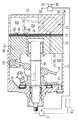
As a conventional capacity control valve for a compressor, for example, there is one disclosed in JP-A-5-99136. That is, as shown in FIGS. 6 and 7, the
[0004]
The
[0005]
For example, when the suction pressure in the
[0006]
The
[0007]
In the capacity control valve having the above configuration, for example, from the state shown in FIG. 6, when the input current value to the
[0008]
Immediately after maximizing the input current value to the
[0009]
When the discharge capacity decreases, the suction pressure of the
[0010]
As described above, the operating areas of the
[0011]
[Problems to be solved by the invention]
However, in the capacity control valve disclosed in Japanese Patent Laid-Open No. 5-99136, in order to realize a configuration in which the
[0012]
In order to solve such a problem, it is only necessary to secure a long seal section distance between the inner peripheral surface of the
[0013]
The present invention has been made paying attention to the problems existing in the above-described prior art, and its purpose is to achieve good capacity controllability in a configuration in which the first valve body and the second valve body do not open simultaneously. Another object of the present invention is to provide a displacement control valve for a variable displacement compressor that can achieve a good response of displacement control.
[0014]
[Means for Solving the Problems]
In order to achieve the above object, according to the first aspect of the present invention, the discharge capacity is changed by opening and closing the extraction passage communicating the suction pressure region and the crank chamber and the air supply passage communicating the crank chamber and the discharge pressure region. A capacity control valve for a variable displacement compressor, which is defined in a valve housing and is provided in a bleed passage, and is accommodated in the first valve chamber, and opens and closes the first valve hole. A first valve body, a second valve chamber defined in the valve housing and provided on the air supply passage, a second valve body housed in the second valve chamber and opening and closing the second valve hole; A movable valve seat that is formed in the valve housing so as to be movable in the same direction as the movement direction of the first valve body; a position of the movable valve seat on the first valve chamber side; And a valve seat biasing section that biases the movable valve seat toward the first valve chamber. A material, a transmission member that transmits the displacement of the movable valve seat to the second valve body, a pressure-sensitive member that is operatively connected to the first valve body and operates the first valve body according to the pressure in the suction pressure region, And a set suction pressure changing means for changing the set suction pressure that is a reference for the operation of the pressure-sensitive member by being controlled by the signal, and the movable valve seat of the second valve body is in contact with the valve seat defining portion. In the state, the second valve hole is closed, and the first valve body moves against the urging force of the valve seat urging member together with the movable valve seat in a state where the first valve hole is closed. The capacity control valve is configured to open the valve.
[0015]
According to a second aspect of the present invention, the set suction pressure changing means generates a suction force between the fixed suction element, the plunger operatively connected to the first valve body, and the fixed suction element and the plunger according to the input current value. The solenoid part is composed of a coil to be changed, and the solenoid part is configured to increase the set suction pressure as the input current value to the coil decreases and to set the set suction pressure to the maximum value when the coil is not energized. is there.
[0016]
In the third aspect of the invention, a part of the bleed passage is common between the opening / closing position of the first valve element and the crank chamber, and a part of the supply passage between the opening / closing position of the second valve element and the crank chamber. It consists of a passage.
[0017]
(Function)
In the invention of
[0018]
The set suction pressure changing means changes an urging force applied to the first valve body by being controlled by an external signal, and changes a set suction pressure that serves as a reference for the operation of the pressure-sensitive member.
Now, when the set suction pressure is set high, for example, when the force in the direction of closing the first valve hole acting on the first valve body becomes larger than a predetermined value, the first valve body opens the first valve hole. In the closed state, it further moves against the biasing force of the valve seat biasing member together with the movable valve seat. Accordingly, the movable valve seat is released from the contact state with the valve seat defining portion, and the second valve body moves by receiving the displacement of the movable valve seat through the transmission member, thereby opening the second valve hole. As a result, high-pressure gas is supplied from the discharge pressure region to the crank chamber, the crank chamber is quickly boosted, and the discharge capacity is reduced with good responsiveness.
[0019]
From this state, when the force in the direction of closing the first valve hole acting on the first valve body is smaller than a predetermined value, the first valve body is movable while the first valve body is blocking the first valve hole. The coupling system of the valve seat and the transmission member moves together, and the second valve body decreases the opening of the second valve hole. The movable valve seat is brought into contact with the valve seat defining portion, the second valve hole is closed by the second valve body, and the crank chamber pressure is controlled only by the first valve body.
[0020]
In the invention of
[0021]
In the invention of claim 3, the space efficiency inside the compressor is improved as compared with the case where the extraction passage and the supply passage are formed separately.
[0022]
DETAILED DESCRIPTION OF THE INVENTION
Hereinafter, an embodiment in which the present invention is embodied in a capacity control valve of a variable capacity compressor used in a vehicle air conditioner will be described.
[0023]
First, the configuration of a variable capacity compressor (hereinafter simply referred to as a compressor) will be described.
As shown in FIG. 1, the
[0024]
The
[0025]
The
[0026]
The cylinder bore 21 is formed through the
[0027]
The suction chamber 24 that constitutes the suction pressure region and the
[0028]
The
[0029]
A vehicle
[0030]
Next, the configuration of the
As shown in FIGS. 2 and 3, the
[0031]
The valve
[0032]
The valve
[0033]
The
[0034]
The
[0035]
The
[0036]
The
[0037]
For example, when the
[0038]
The
[0039]
The
[0040]
Next, the operation of the
When the vehicle engine Eg is started and the detected temperature from the passenger
[0041]
In the state where the clutch mechanism C is connected, the control computer X calculates the input current value based on the external signal such as the room temperature set by the passenger compartment
[0042]
In the
For example, when the cooling load is large, the difference between the detected temperature from the passenger
[0043]
If the opening degree of the
[0044]
On the other hand, when the cooling load is small, the difference between the temperature detected by the passenger
[0045]
If the opening degree of the
[0046]
Here, when the current is input from the
[0047]
When there is almost no cooling load and there is almost no difference between the temperature detected by the passenger
[0048]
When the discharge capacity decreases, the suction pressure of the
[0049]
As described above, in the
[0050]
In the present embodiment having the above-described configuration, the following effects are obtained.
(1) In order to embody a configuration in which the
[0051]
(2) The
[0052]
(3) Between the opening / closing position (first valve hole 46) of the
[0053]
In addition, for example, the following modes can be implemented without departing from the spirit of the present invention.
As shown in FIG. 5, the
[0054]
For example, as shown by a virtual line in FIG. 5, a
[0055]
○ Use a diaphragm instead of the
○ The
○ In the
[0056]
○ The
[0057]
A technical idea that can be grasped from the above embodiment will be described.
(1) The set suction pressure changing means includes a fixed
[0058]
In this way, when the
[0059]
(2) The capacity control valve according to any one of
[0060]
In this way, the sealing performance between the
(3) The capacity control valve according to any one of
[0061]
In this way, the
[0062]
【The invention's effect】
According to the present invention having the above-described configuration, the valve seat forming the first valve hole is configured to be movable in order to realize a configuration in which the first valve body and the second valve body do not open simultaneously. Here, since the valve seat has a movable configuration, it is necessary to newly consider gas leakage from between the sliding surfaces of the valve housing and the movable valve seat. In order to avoid this gas leakage, the movable valve seat may be enlarged to ensure a long seal section between the sliding surfaces with the valve housing. Even if the movable valve seat is increased in size (increased in weight), it does not affect the opening / closing operation of the first valve hole by the first valve body in accordance with the suction pressure. In other words, in the present invention, it is possible to achieve both good capacity controllability and good capacity control responsiveness, one of which must be sacrificed in the capacity control valve of JP-A-5-99136. It becomes.
[Brief description of the drawings]
FIG. 1 is a longitudinal sectional view of a variable capacity compressor.
FIG. 2 is an enlarged sectional view of a capacity control valve.
FIG. 3 is a diagram for explaining the operation of a capacity control valve.
FIG. 4 is a chart for explaining operation characteristics of a capacity control valve.
FIG. 5 is an enlarged cross-sectional view of a main part of a capacity control valve showing another example.
FIG. 6 is an enlarged sectional view of a conventional capacity control valve.
FIG. 7 is a diagram for explaining the operation of a capacity control valve.
[Explanation of symbols]
DESCRIPTION OF
Claims (3)
バルブハウジングに区画形成され、抽気通路上に設けられた第1弁室と、
第1弁室に収容され、第1弁孔を開閉する第1弁体と、
バルブハウジングに区画形成され、給気通路上に設けられた第2弁室と、
第2弁室に収容され、第2弁孔を開閉する第2弁体と、
第1弁孔を形成し、バルブハウジングにおいて第1弁体の移動方向と同方向へ移動可能に保持された可動弁座と、
バルブハウジングに設けられ、可動弁座の第1弁室側での位置を当接規定する弁座規定部と、
可動弁座を第1弁室側に付勢する弁座付勢部材と、
可動弁座の変位を第2弁体に伝達する伝達部材と、
第1弁体に作動連結され、吸入圧領域の圧力に応じて第1弁体を作動させる感圧部材と、
外部信号によって制御されることで、感圧部材の動作の基準となる設定吸入圧力を変更する設定吸入圧力変更手段とを備え、
前記第2弁体は可動弁座が弁座規定部に当接した状態では第2弁孔を閉塞し、第1弁体が第1弁孔を閉塞した状態にて可動弁座とともに弁座付勢部材の付勢力に抗して移動することで、第2弁孔を開放する構成の容量制御弁。This is a displacement control valve for a variable displacement compressor that opens and closes a bleed passage that connects the suction pressure region and the crank chamber and an air supply passage that connects the crank chamber and the discharge pressure region to change the discharge capacity. And
A first valve chamber defined in the valve housing and provided on the extraction passage;
A first valve body housed in the first valve chamber and opening and closing the first valve hole;
A second valve chamber defined in the valve housing and provided on the air supply passage;
A second valve body housed in the second valve chamber and opening and closing the second valve hole;
A movable valve seat that forms a first valve hole and is held in the valve housing so as to be movable in the same direction as the movement direction of the first valve body;
A valve seat defining portion that is provided in the valve housing and abuts and defines the position of the movable valve seat on the first valve chamber side;
A valve seat biasing member that biases the movable valve seat toward the first valve chamber;
A transmission member for transmitting the displacement of the movable valve seat to the second valve body;
A pressure-sensitive member that is operatively connected to the first valve body and operates the first valve body in accordance with the pressure in the suction pressure region;
A set suction pressure changing means for changing the set suction pressure that is a reference for the operation of the pressure-sensitive member by being controlled by an external signal;
The second valve body closes the second valve hole when the movable valve seat is in contact with the valve seat defining portion, and has a valve seat together with the movable valve seat when the first valve body closes the first valve hole. A capacity control valve configured to open the second valve hole by moving against the urging force of the urging member.
Priority Applications (2)
| Application Number | Priority Date | Filing Date | Title |
|---|---|---|---|
| JP05249499A JP3750397B2 (en) | 1999-03-01 | 1999-03-01 | Capacity control valve for variable capacity compressor |
| EP00104150A EP1033489A3 (en) | 1999-03-01 | 2000-02-29 | Displacement control valve for variable displacement type compressors |
Applications Claiming Priority (1)
| Application Number | Priority Date | Filing Date | Title |
|---|---|---|---|
| JP05249499A JP3750397B2 (en) | 1999-03-01 | 1999-03-01 | Capacity control valve for variable capacity compressor |
Publications (2)
| Publication Number | Publication Date |
|---|---|
| JP2000249050A JP2000249050A (en) | 2000-09-12 |
| JP3750397B2 true JP3750397B2 (en) | 2006-03-01 |
Family
ID=12916280
Family Applications (1)
| Application Number | Title | Priority Date | Filing Date |
|---|---|---|---|
| JP05249499A Expired - Fee Related JP3750397B2 (en) | 1999-03-01 | 1999-03-01 | Capacity control valve for variable capacity compressor |
Country Status (2)
| Country | Link |
|---|---|
| EP (1) | EP1033489A3 (en) |
| JP (1) | JP3750397B2 (en) |
Cited By (1)
| Publication number | Priority date | Publication date | Assignee | Title |
|---|---|---|---|---|
| WO2008102599A1 (en) * | 2007-02-19 | 2008-08-28 | Sanden Corporation | Volume control valve for variable displacement compressor |
Families Citing this family (11)
| Publication number | Priority date | Publication date | Assignee | Title |
|---|---|---|---|---|
| JP3943871B2 (en) * | 2001-07-25 | 2007-07-11 | 株式会社テージーケー | Variable capacity compressor and capacity control valve for variable capacity compressor |
| US6715995B2 (en) | 2002-01-31 | 2004-04-06 | Visteon Global Technologies, Inc. | Hybrid compressor control method |
| JP4152674B2 (en) * | 2002-06-04 | 2008-09-17 | 株式会社テージーケー | Capacity control valve for variable capacity compressor |
| JP2006097665A (en) * | 2004-06-28 | 2006-04-13 | Toyota Industries Corp | Capacity control valve in variable displacement compressor |
| DE102005031511A1 (en) | 2005-07-06 | 2007-01-11 | Daimlerchrysler Ag | Control valve for a refrigerant compressor and refrigerant compressor |
| JP6140315B2 (en) * | 2010-09-06 | 2017-05-31 | 株式会社不二工機 | Control valve for variable displacement compressor |
| JP5740596B2 (en) * | 2011-04-20 | 2015-06-24 | 株式会社テージーケー | Control valve |
| JP6085789B2 (en) * | 2012-12-27 | 2017-03-01 | 株式会社テージーケー | Control valve for variable capacity compressor |
| JP6115393B2 (en) | 2013-08-08 | 2017-04-19 | 株式会社豊田自動織機 | Variable capacity swash plate compressor |
| KR102051661B1 (en) | 2017-05-30 | 2019-12-04 | 한온시스템 주식회사 | Control valve and variable capacity type compressure |
| JP2019094780A (en) * | 2017-11-17 | 2019-06-20 | サンデン・オートモーティブコンポーネント株式会社 | Capacity control valve for clutch slant plate type variable displacement compressor with clutch |
Family Cites Families (4)
| Publication number | Priority date | Publication date | Assignee | Title |
|---|---|---|---|---|
| US4606705A (en) * | 1985-08-02 | 1986-08-19 | General Motors Corporation | Variable displacement compressor control valve arrangement |
| JPH0784865B2 (en) * | 1986-12-16 | 1995-09-13 | カルソニック株式会社 | Controller for variable capacity swash plate type compressor |
| SG30647G (en) * | 1991-01-28 | 1995-09-01 | Sanden Corp | Slant plate type compressor with variable displacement mechanism |
| JPH0599136A (en) | 1991-10-23 | 1993-04-20 | Sanden Corp | Variable capacity type swash plate type compressor |
-
1999
- 1999-03-01 JP JP05249499A patent/JP3750397B2/en not_active Expired - Fee Related
-
2000
- 2000-02-29 EP EP00104150A patent/EP1033489A3/en not_active Withdrawn
Cited By (1)
| Publication number | Priority date | Publication date | Assignee | Title |
|---|---|---|---|---|
| WO2008102599A1 (en) * | 2007-02-19 | 2008-08-28 | Sanden Corporation | Volume control valve for variable displacement compressor |
Also Published As
| Publication number | Publication date |
|---|---|
| EP1033489A2 (en) | 2000-09-06 |
| JP2000249050A (en) | 2000-09-12 |
| EP1033489A3 (en) | 2001-01-10 |
Similar Documents
| Publication | Publication Date | Title |
|---|---|---|
| EP0953765B2 (en) | Variable displacement type swash plate compressor and displacement control valve | |
| JP3432995B2 (en) | Control valve for variable displacement compressor | |
| US6361283B1 (en) | Displacement control valve | |
| JP3728387B2 (en) | Control valve | |
| JP4081965B2 (en) | Capacity control mechanism of variable capacity compressor | |
| JP6138156B2 (en) | Capacity control valve | |
| US6390782B1 (en) | Control valve for a variable displacement compressor | |
| JP3432994B2 (en) | Control valve for variable displacement compressor | |
| EP2113662B1 (en) | Variable displacement type compressor with displacement control mechanism | |
| KR100325789B1 (en) | Variable displacement compressors and control valves for variable displacement compressors | |
| JP3585150B2 (en) | Control valve for variable displacement compressor | |
| JP3750397B2 (en) | Capacity control valve for variable capacity compressor | |
| JP3731434B2 (en) | Control valve for variable capacity compressor | |
| JPH06200875A (en) | Rocking swash plate type variable displacement compressor | |
| EP1046818B1 (en) | Capacity controller of a compressor with variable capacity | |
| JP3899719B2 (en) | Control valve for variable capacity compressor | |
| JPH01190972A (en) | Variable displacement swash plate-type compressor | |
| JP2007064028A (en) | Variable displacement compressor | |
| JP3089775B2 (en) | Variable capacity compressor | |
| JP3582229B2 (en) | Variable displacement compressor and control method thereof | |
| JP4647471B2 (en) | Variable capacity swash plate compressor and air conditioning cooling circuit | |
| JPH03199677A (en) | Variable volume type swash plate compressor | |
| JPH10103249A (en) | Control valve | |
| JP2011027115A (en) | Variable displacement swash plate type compressor and cooling circuit for air conditioning | |
| JP3114386B2 (en) | Variable displacement compressor |
Legal Events
| Date | Code | Title | Description |
|---|---|---|---|
| A621 | Written request for application examination |
Free format text: JAPANESE INTERMEDIATE CODE: A621 Effective date: 20040723 |
|
| A977 | Report on retrieval |
Free format text: JAPANESE INTERMEDIATE CODE: A971007 Effective date: 20051101 |
|
| TRDD | Decision of grant or rejection written | ||
| A01 | Written decision to grant a patent or to grant a registration (utility model) |
Free format text: JAPANESE INTERMEDIATE CODE: A01 Effective date: 20051115 |
|
| A61 | First payment of annual fees (during grant procedure) |
Free format text: JAPANESE INTERMEDIATE CODE: A61 Effective date: 20051128 |
|
| LAPS | Cancellation because of no payment of annual fees |