JP3746452B2 - Spare seedling storage device for riding type rice transplanter - Google Patents
Spare seedling storage device for riding type rice transplanter Download PDFInfo
- Publication number
- JP3746452B2 JP3746452B2 JP2001391241A JP2001391241A JP3746452B2 JP 3746452 B2 JP3746452 B2 JP 3746452B2 JP 2001391241 A JP2001391241 A JP 2001391241A JP 2001391241 A JP2001391241 A JP 2001391241A JP 3746452 B2 JP3746452 B2 JP 3746452B2
- Authority
- JP
- Japan
- Prior art keywords
- seedling
- posture
- support
- column
- seedling storage
- Prior art date
- Legal status (The legal status is an assumption and is not a legal conclusion. Google has not performed a legal analysis and makes no representation as to the accuracy of the status listed.)
- Expired - Fee Related
Links
Images


Description
【0001】
【発明の属する技術分野】
本発明は、運転部を備えた走行機体の後部に、苗植付装置を昇降操作自在に連結し、前記走行機体に、上下複数段の苗載せ棚が付いている予備苗収容部を備えてある乗用型田植機の予備苗収容装置に関する。
【0002】
【従来の技術】
上記予備苗収容装置として、従来、たとえば実公平2−32006号公報に示されるように、予備苗収容部が、走行機体によって前後揺動自在に支持されている前後一対の支柱にわたって連結しており、支柱を起立姿勢にすることにより、上下複数段の苗載せ棚が運転部の方に寄るとともに前後方向で水平な姿勢になり、予備苗を苗載せ棚から取出して苗植付装置に供給する苗補給が運転部から行いやすくなる。支柱を機体前方側に倒伏させることにより、各苗載せ棚が植付け作業時よりも前方に移動して苗載せ棚を畦に近づけやすくなるものがあった。
【0003】
【発明が解決しようとする課題】
上記した従来の予備苗収容装置にあっては、苗載せ棚を前方に移動させて苗積み込みを行う際も、各苗載せ棚が前後方向で水平な姿勢になるものであった。この種の予備苗収容装置にあっては、苗載せ棚が前方に移動するに伴って下降することにより、殊に圃場面よりも高レベルに位置する畦上から下段側の苗載せ棚に苗積み込みする際、苗載せ棚が低くなり、苗を棚に入れにくくなることがあった。
【0004】
本発明の目的は、運転部にて予備苗収容部から苗植付装置に苗補給することも、予備苗収容装置に苗積み込みすることも容易な乗用型田植機の予備苗収容装置を提供することにある。
【0005】
【課題を解決するための手段】
請求項1による発明の構成、作用、効果はつぎのとおりである。
【0006】
[構成]
運転部を備えた走行機体の後部に、苗植付装置を昇降操作自在に連結し、前記走行機体に、上下複数段の苗載せ棚が付いている予備苗収容部を備えてある乗用型田植機の予備苗収容装置において、
前記予備苗収容部のための支柱を、走行機体の前部の横側方で起立した起立姿勢と、この起立姿勢から機体前方側に傾いた傾斜姿勢とに揺動切換え自在に走行機体に取付け、予備苗収容部を支柱に対して姿勢変更自在に連結してあるとともに、
支柱が前記起立姿勢に切り換えられると、予備苗収容部が各苗載せ棚を機体前後方向で水平な姿勢にする連結姿勢で支柱に連結した状態になり、支柱が前記傾斜姿勢に切り換えられると、予備苗収容部が各苗載せ棚を前側上りの傾斜姿勢にする連結姿勢で支柱に連結した状態になるように、予備苗収容部の支柱に対する連結姿勢を支柱の揺動に伴って自動的に変更する姿勢変更手段を備え、
前記予備収容部と、その予備苗収容部の前後を支持する前後一対の支柱と、前後の支柱間における走行機体とによって、前記予備収容部の姿勢を変更する不等辺四連リンク機構を構成し、この不等辺四連リンク機構を前記姿勢変更手段とし、
前記支柱が前記起立姿勢に切り換わった状態において前記予備苗収容部が支柱に対して車体横方向に相対移動することを抑制するように予備苗収容部と支柱を車体横方向に係合させる係合手段を、支柱と予備苗収容部の車体上下方向での相対移動を許容するように車体上下方向で非係合な状態で設けてある。
【0007】
[作用]
支柱が前後に揺動されると、それに付いて予備苗収容部が前後に移動し、支柱が前記起立姿勢にされた場合には、前記傾斜姿勢にされた場合よりも予備苗収容部が運転部に近づき、支柱が前記傾斜姿勢にされた場合には、前記起立姿勢にされた場合よりも予備苗収容部が機体前方側に位置する。支柱が前後に揺動されると、予備苗収容部の支柱に対する連結姿勢が姿勢変更手段によって変更され、支柱が前記起立姿勢にされた場合には、予備苗収容部が支柱に対して前記連結姿勢になって各苗載せ棚が機体前後方向で水平な姿勢になり、支柱が前記傾斜姿勢にされた場合には、予備苗収容部が支柱に対して前記連結姿勢になって各苗載せ棚が前側上りの傾斜姿勢になるものである。
これにより、支柱を起立姿勢に切り換えることにより、各苗載せ棚を運転部の方に寄せるとともに前後方向で水平の姿勢にしておくことができ、支柱を傾斜姿勢に切り換えることにより、各苗載せ棚を機体前方側に移動させるとともに前上り姿勢にすることができる。
【0008】
[効果]
従って、植付け作業を行う際は、各苗載せ棚を運転部の方に寄せるとともに前後方向で水平な姿勢にしておき、苗植付装置に苗補給するに当たり、運転部に居ても苗を苗載せ棚から容易に取出して楽に行える。
予備苗収容部に予備苗を積み込むに当たり、各苗載せ棚を作業時よりも前方に移動させるとともに前上り姿勢にし、苗載せ棚を畦に容易に近づけるとともに、下段側の苗載せ棚にも苗を容易に差し入れて楽に能率よく積み込み作業できる。
【0009】
【0010】
【0011】
[作用]
支柱が前後に揺動すると、支柱や予備苗収容部で成る不等辺四連リンク機構のために、予備苗収容部の支柱に対する連結姿勢が変化し、各苗載せ棚が運転部の方で水平姿勢に、前方側で前上がり傾斜になるものである。
【0012】
[効果]
従って、支柱や予備苗収容部を不等辺四連リンク機構が構成されるように組み合わせるだけで構造簡単に苗載せ棚の姿勢変化を可能にでき、経済面で有利に得られる。
【0013】
【0014】
【0015】
【0016】
【0017】
請求項2による発明の構成、作用、効果はつぎのとおりである。
【0018】
[構成]
請求項1による発明の構成において、前記支柱を前記起立姿勢及び前記傾斜姿勢にロックする支柱ロック機構を備えて、支柱ロック機構をロック解除側に解除ペダルによって切り換え操作するように構成してある。
【0019】
[作用]
予備苗収容部やこれに積み込んだ苗などによる荷重が支柱ロック機構に掛かっていると、支柱ロック機構が外れにくくなるが、予備苗収容部や支柱などを手で支持して支柱ロック機構に荷重が掛からないようしながら、解除ペダルを足で操作して支柱ロック機構をロック解除側に切り換え操作することができるものである。
【0020】
[効果]
従って、予備苗収容部の移動操作を行うに当たり、支柱のロック解除を軽く行って迅速かつ楽に行える。
【0021】
請求項3による発明の構成、作用、効果はつぎのとおりである。
【0022】
[構成]
請求項1又は2による発明の構成において、前記支柱に対して起立操作力を付与する起立付勢手段を備えてある。
【0023】
[作用]
支柱を起立側に操作する際、起立付勢手段によって起立操作力が付与され、その分、人為操作力を軽く済ませながら起立操作できるものである。
【0024】
[効果]
従って、苗の積み込みが終えた予備苗収容部を運転部の方に戻す際、苗のために重くなっていても、起立付勢手段によって助けられて比較的楽に操作できる。
【0025】
【発明の実施の形態】
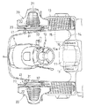
図1に示すように、左右一対の操向操作及び駆動自在な前車輪1、左右一対の駆動自在な後車輪2、機体前端部に位置する原動部3、この原動部3の後方に位置する運転座席11などを有する搭乗型の運転部10を備えた走行機体の機体フレーム5の後端部に、リンク機構6を介して苗植付装置7を連結するとともに、リンク機構6と機体フレーム5とにわたって連結している油圧式のリフトシリンダ9によってリンク機構6を機体フレーム5に対して上下に揺動操作して苗植付装置7を昇降操作するように構成し、原動部3に位置するエンジンの出力を回転軸8によって苗植付装置7に伝達するように構成して、苗植付装置7を接地フロート7bが圃場の泥土に接地する下降位置にして走行機体を走行させることにより、苗植付装置7が機体横方向に並ぶ複数個の苗植付機構7aによって圃場に苗植え付けをしていくように乗用型田植機を構成してある。
【0026】
図1、図2に示すように、走行機体の原動部3の両横側に、上下複数段の苗載せ棚21を有する予備苗収容装置を設けてある。左右の予備苗収容装置は同様に構成してあり、各予備苗収容装置は、次の如く構成してある。
【0027】
すなわち図1などに示すように、予備苗収容装置は、走行機体が運転部10のフロア12を支持するように備えている運転部フレーム13の前側に下端側が連結しているパイプ材で成る支柱31と、前記運転部フレーム13の後側に下端側が連結しているパイプ材で成る支柱32と、前記上下複数段の合成樹脂製の苗載せ棚21を棚支持枠22の前後一対の棚支持部22aにわたって取付けて成る予備苗収容部20とを備えて構成してある。
【0028】
図3、図5などに示すように、前記前後一対の支柱31,32のうちの前側の支柱31の下端側も、後側の支柱32の下端側も、運転部フレーム13にパイプ材の下端側を固定して設けた支柱支持部33,34の上端側に連結ピン35,36によって回動自在に連結しており、前側の支柱31も、後側の支柱32も、走行機体に対して連結ピン35,36の機体横向きの軸芯35a,36aまわりで前後に揺動するように付いている。
【0029】
予備苗収容部20の前記棚支持枠22は、両端側が前記棚支持部22aになり、中間部が両棚支持部22aの上端部どうしを連結している連結部22bになるように屈曲成形した一本の丸パイプ材と、両棚支持部22aの下端側どうしの開き止めを行うように丸パイプ材の端部どうしにわたって連結した丸棒製の連結杆23とによって構成してある。一方の棚支持部22aの上端側が前側の支柱31の上端側に連結ピン24によって相対回動自在に連結し、他方の棚支持部22aの上端側が後側の支柱32の上端側に連結ピン25によって相対回動自在に連結していることにより、予備苗収容部20は、棚支持枠22の上端側で、前側の支柱31と後側の支柱32の上端部どうしにわたって連結しているとともに、前側の支柱31に対しても、後側の支柱32に対しても連結ピン24,25の機体横向きの軸芯24a,25aまわりで相対回動するように連結している。
【0030】
後側の支柱32の支柱支持部34に対して回動自在に連結している連結点としての前記軸芯36aから、予備苗収容部20が相対回動自在に連結している連結点としての前記軸芯25aまでの直線距離が、前側の支柱31の支柱支持部33に対して回動自在に連結している連結点としての前記軸芯35aから、予備苗収容部20が相対回動自在に連結している連結点としての前記軸芯24aまでの直線距離より小になるように構成してあり、走行機体の運転部フレーム13と、前後一対の支柱31,32と、予備苗収容部20とが不等辺四連リンク機構Lを構成している。
【0031】
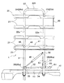
すなわち、前後の支柱31,32を連動させて機体前後方向に揺動操作することができ、この揺動操作を行うことにより、前後の支柱31,32は、図5に示す如く後側の支柱32の下端側に付設してある姿勢決め部材37が支柱支持部34に当接して原動部3の横側方で起立した起立姿勢と、図6に示す如く前側の支柱31の前記連結ピン35と後側の支柱32の支持ピン38とにわたって取付けてあるガスダンパ40が限界まで短縮した前倒れ姿勢とに切り換わる。前後の支柱31,32を揺動操作すれば、前記不等辺四連リンク機構Lの作用のために予備苗収容部20が前後支柱31,32の上端側に付いて機体前後方向に移動するとともに予備苗収容部20の前後支柱31,32に対する連結姿勢が支柱31,32の揺動に伴って自動的に変化し、前後の支柱31,32を前記起立姿勢にした場合には、予備苗収容部20が原動部3の横側に位置するとともに全ての苗載せ棚21を機体前後方向で水平な姿勢にした苗収容用の取付け姿勢になり、前後の支柱31,32が前記前倒れ姿勢になった場合には、予備苗収容部20が支柱起立姿勢の場合よりも機体前方側に移動した位置になるとともに全ての苗載せ棚21を前上りの傾斜姿勢にした苗積込み用の取付け姿勢になるように構成してある。
【0032】
図8などに示すように、前側の支柱31の前記連結ピン35に一端側が回動自在に連結しているとともに他端側に解除ペダル51が付いているロック杆52と、このロック杆52の遊端側と後側の支柱32が備えているばね掛け具53とにわたって取付けたロックばね54と、前記姿勢決め部材37の端部に付設してあるロックピン55とより、前後の支柱31,32を前記起立姿勢や前記前倒れ姿勢にロックする支柱ロック機構50を構成してある。
すなわち、図8(イ)に示すように、後側の支柱32が前記起立姿勢に切換えられると、前記ロックばね54によるロック杆52の揺動付勢のために、ロック杆52がこれの2個の切欠き52a,52bの一方52aでロックピン55に引っ掛かる。図8(ロ)に示すように、後側の支柱32が前記前倒れ姿勢に切り換えられると、ロックばね54によるロック杆52の揺動付勢のために、ロック杆52が他方の切欠き52bによってロックピン55に引っ掛かる。すると、いずれの場合も、支柱ロック機構50は、ロック杆52によって後側の支柱32を起立姿勢や前倒れ姿勢に突っ張り支持することにより、前後の両支柱31,32を起立姿勢や前倒れ姿勢にロックするようにロック状態になる。
両支柱31,32を起立姿勢と前倒れ姿勢のいずれにロックしている場合でも、解除ペダル51を踏み込み操作すると、ロック杆52がロックばね54に抗して下降側に揺動してロックピン55から外れる。これにより、支柱ロック機構50は、前後の支柱31,32の揺動を可能にするようにロック解除状態になる。
【0033】
前記ガスダンパ40は、前側の支柱31の前記連結ピン35に一端側が相対回動自在に連結しているロッドと、このロッドが摺動自在に入り込んでいるとともに後側の支柱32の前記連結ピン38に一端側が相対回動自在に連結しているチューブと、ロッドをチェーブから突出付勢するように構成してチェーブの内部に充填してあるガスとで成り、後側の支柱32を直接に起立側に揺動付勢することにより、前後の両支柱31,32に対して起立操作力を付与している。
【0034】
図5などに示すように、前記前後の支柱31,32の中間どうしにわたって移動ガイド41を取付けてある。図7に示すように、この移動ガイド41は、一端側が機体前後方向に沿う取付け杆部42になり、他端側が機体前後方向に沿うガイドレール部43になるように、両端部どうしの間に開口44ができるように細長いU字状に屈曲成形した1本の丸棒材で成り、取付け杆部42の一端側が連結ピン45によって後側の支柱32に固定し、他端側が移動ガイド41の長孔46に摺動自在に入り込むように構成して前側の支柱31に固定してある連結ピン47によって前側の支柱31に相対摺動自在に連結していることによって前側の支柱31と後側の支柱32とによって支持されており、前後の支柱31,32が前記起立姿勢と前倒れ姿勢とにわたって揺動して予備苗収容部20が前後に移動する際、予備苗収容部20の棚支持枠22の後側の棚支持部22aがガイドレール部43と取付け杆部42との間を移動し、予備苗収容部20の棚支持枠22の前側の棚支持部22aがガイドレール部43と取付け杆部42との間に対して出入りするように構成してある。すなわち、予備苗収容部20が前後の支柱31,32に対してこれらへの連結点を中心にして機体横方向に揺れ動くことがあれば、棚支持枠22の前後の棚支持部22aがガイドレール部43に当接しながら移動する。これにより、移動ガイド41は、ガイドレール部43を予備苗収容部20の苗棚支持枠22の下端側に機体横方向から受け止め作用させ、このガイドレール部43によって予備苗収容部20を横揺れしにくいように支持しながら前後移動するように案内する。
【0035】
つまり、左右の予備苗収容装置は、予備苗の積み込みや、積み込み苗の収容を行うに当たり次の如く行えるようにしてある。
予備苗の積み込みを行うに当たり、運転部10のフロア12に立って、後側の支柱32の上端側に屈曲丸棒材を取付けて設けてある図6の如き固定ハンドル39を持って前後の支柱31,32を前記起立姿勢から機体前方側に揺動操作して前記前倒れ姿勢に切り換える。すると、図4に示すように、予備苗収容部20の各苗載せ棚21が作業時よりも機体前方側に移動するとともに前上り傾斜の姿勢になり、各苗載せ棚21を畦に近づけやすくなり、かつ、畦から各苗載せ棚21に予備苗を差し入れやすくなる。このとき、前後の支柱31,32が前倒れ姿勢に支柱ロック機構50によってロックされており、支柱31,32が前後方向に揺れ動いて予備苗収容部20が揺れ動くことを抑制しながら予備苗を苗載せ棚21に差し入れられる。また、予備苗収容部20が移動ガイド41による受止めのために横揺れすることを抑制しながらできる。
【0036】
この予備苗積み込みを終えると、前後の支柱31,32を機体後方側に揺動操作して起立姿勢に切り換える。このとき、ガスダンパ40によって起立操作力が付与され、その分人為操作力を軽く済ませながら起立操作できる。前後の支柱31,32が起立姿勢になると、各苗載せ棚21が予備苗の積み込みを行う場合よりも後方側に移動して運転部10に寄った箇所に前後方向で水平な姿勢になって位置し、各苗載せ棚21に積み込まれた予備苗を、運転部10からでも容易に取出して苗植付装置7の苗載せ台7cに供給することができるように収容できる。このとき、前後の支柱31,32が起立姿勢に支柱ロック機構50によってロックされており、支柱31,32が前後に揺れ動くことを抑制しながら走行したり、予備苗取出しをすることができる。また、予備苗収容部20が移動ガイド41による受止めのために横揺れすることを抑制しながらできる。
【0037】
支柱31,32を起立姿勢から前倒れ姿勢に切り換える際も、前倒れ姿勢から起立姿勢に切り換える際も、予備苗収容部20や支柱31,32などを手で支持して支柱ロック機構50に予備苗収容部20や予備苗の荷重が掛からないようしながら、解除ペダル51を足で操作することにより、支柱ロック機構50をロック解除側に軽く切り換え操作できる。
【0038】
図2、図9に示すように、運転部10のフロア14の機体横一端側での下方にエンジン用の燃料タンク15を設けてある。この燃料タンク15から延出する給油筒16の注油口16aを、運転座席11のバッテリー18が位置する側とは反対側の横側の下方に配置し、運転座席11をこれの前端側に位置する支軸11aの軸芯まわりで上昇揺動させて、燃料タンク15に燃料供給するようにしてある。
【0039】
運転座席11の下方に検出スイッチ19を設けるとともに、この検出スイッチ19は、運転座席11が上昇揺動されると、このことを検出し、この検出結果をエンジン停止装置に停止作動を実行させるべく出力するように構成してある。
つまり、燃料タンク15に燃料供給するに当たり、エンジンを駆動させたままで運転座席11が上昇されても、自動的にエンジンが停止するようにしてある。
【0040】
[別実施形態]
上記実施形態の如く不等辺四連リンク機構Lを採用する他、予備苗収容部20と、前後の支柱31,32と、運転部フレーム13とが等辺平行四連リンク機構を構成するように構成するとともに、支柱31,32が前後に揺動するに伴って予備苗収容部20の棚支持枠22を支柱31,32に対して回動操作して予備苗収容部20の支柱31,32に対する連結姿勢を変化させるように支柱31,32と予備苗収容部20との間に設けたギヤ機構などを採用することにより、支柱31,32の揺動に伴って予備苗収容部20の支柱31,32に対する連結姿勢が変化して、苗載せ棚21が水平姿勢と前上がり傾斜姿勢とに変化するように構成して実施してもよい。従って、これら不等辺四連リンク機構Lやギヤ機構などを総称して姿勢変更手段Lと呼称する。
【0041】
前記ガスダンパ40に替えてスプリングを採用して実施してもよいのであり、これらを総称して起立付勢手段40と呼称する。
【図面の簡単な説明】
【図1】 乗用型田植機全体の側面図
【図2】 乗用型田植機前部の平面図
【図3】 予備苗収容装置の正面図
【図4】 乗用型田植機前部の予備苗積み込み状態での側面図
【図5】 予備苗収容装置の苗収容状態での側面図
【図6】 予備苗収容装置の苗積み込み状態での側面図
【図7】 移動ガイドの平面図で、(イ)は、支柱起立状態の場合を示し、(ロ)は、支柱前傾状態の場合を示す。
【図8】 支柱ロック機構の側面図で、(イ)は、支柱起立状態の場合を示し、(ロ)は、支柱前傾状態の場合を示す。
【図9】 燃料タンク注油口の配設部を示す側面図
【符号の説明】
7 苗植付装置
10 運転部
20 予備苗収容部
21 苗載せ棚
31,32 柱
40 起立付勢手段
41 移動ガイド
50 支柱ロック機構
51 解除ペダル[0001]
BACKGROUND OF THE INVENTION
The present invention has a seedling planting device connected to a rear portion of a traveling machine body provided with a driving unit so as to be movable up and down, and the traveling machine body is provided with a spare seedling storage unit with a plurality of upper and lower seedling mounting shelves. The present invention relates to a spare seedling storage device for a riding rice transplanter.
[0002]
[Prior art]
As the preliminary seedling storage device, as shown in, for example, Japanese Utility Model Publication No. 2-32006, a preliminary seedling storage unit is connected across a pair of front and rear columns supported by a traveling machine body so as to be swingable back and forth. By placing the support in a standing posture, the upper and lower multi-stage seedling shelves approach the operating section and become horizontal in the front-rear direction, and the spare seedlings are taken out from the seedling placing shelves and supplied to the seedling planting device It becomes easier to replenish seedlings from the driving department. By tilting the support to the front side of the aircraft, each seedling shelf moved more forward than during planting work, making it easier to bring the seedling shelf closer to the cocoon.
[0003]
[Problems to be solved by the invention]
In the above-described conventional spare seedling storage device, each seedling mounting shelf is in a horizontal posture in the front-rear direction even when the seedling mounting shelf is moved forward to perform seedling loading. In this kind of reserve seedling storage device, the seedling is lowered as the seedling placing shelf moves forward, so that the seedling is loaded onto the seedling placing shelf on the lower side from the uppermost position which is located at a higher level than the field scene. When doing so, the seedling rack was lowered, making it difficult to put the seedling on the shelf.
[0004]
An object of the present invention is to provide a spare seedling storage device for a riding type rice transplanter that can be easily supplied to a seedling planting device from a spare seedling storage unit in a driving unit or loaded into a seedling storage device. There is.
[0005]
[Means for Solving the Problems]
The configuration, operation, and effect of the invention according to
[0006]
[Constitution]
Riding type rice planting which is connected to a rear part of a traveling machine body provided with a driving part so that a seedling planting device can be moved up and down freely, and is provided with a spare seedling container having a plurality of upper and lower seedling racks on the traveling machine body. In the spare seedling storage device of the machine,
The support for the spare seedling storage part is attached to the traveling machine body so as to be swingably switchable between an upright position standing on the lateral side of the front part of the traveling machine body and an inclined posture inclined from the standing position to the front side of the machine body. The spare seedling storage part is connected to the column so that the posture can be freely changed,
When the strut is switched to the standing posture, the spare seedling storage unit is connected to the strut in a connected posture that makes each seedling placing shelf a horizontal posture in the longitudinal direction of the aircraft, and when the strut is switched to the inclined posture, The spare seedling container is automatically connected to the support column in accordance with the swinging of the support column so that the seedling storage unit is connected to the support column in a connected position in which each seedling mounting shelf is inclined upward. A posture changing means for changing,
An unequal side quadruple link mechanism for changing the posture of the preliminary accommodating portion is configured by the preliminary accommodating portion, a pair of front and rear columns supporting the front and rear of the preliminary seedling accommodating portion, and a traveling machine body between the front and rear columns. The unequal side quadruple link mechanism is the posture changing means,
Engagement of the preliminary seedling receiving portion and the support in the vehicle body lateral direction so as to suppress relative movement of the spare seedling storage portion in the vehicle lateral direction with respect to the support when the support is switched to the standing posture. The coupling means is provided in a non-engaged state in the vertical direction of the vehicle body so as to allow relative movement in the vertical direction of the vehicle body between the support column and the spare seedling storage part .
[0007]
[Action]
When the support is swung back and forth, the reserve seedling storage unit moves back and forth. When the support is in the upright position, the reserve seedling storage unit operates more than in the inclined position. When approaching the part and the support column is in the inclined posture, the reserve seedling accommodating portion is located on the front side of the machine body as compared with the case of being in the standing posture. When the support is swung back and forth, the connection posture of the spare seedling storage part with respect to the support is changed by the posture changing means, and when the support is in the standing posture, the standby seedling storage part is connected to the support with the support. Each seedling shelf is in a horizontal position in the front-rear direction of the machine body in the posture, and when the support column is in the inclined posture, the reserve seedling container is in the connection posture with respect to the support column, and each seedling storage shelf Is a front-side uphill inclination posture.
Thereby, by switching the support column to the standing posture, each seedling mounting shelf can be brought close to the operation unit and kept in a horizontal posture in the front-rear direction, and by switching the support column to the inclined posture, each seedling mounting shelf Can be moved to the front side of the fuselage and can be in a front-up position.
[0008]
[effect]
Therefore, when carrying out the planting work, each seedling placing shelf is brought close to the driving unit and is kept in a horizontal posture in the front-rear direction so that the seedlings can be replenished even when in the driving unit. It can be easily removed from the shelf and easily performed.
When loading the spare seedlings into the spare seedling storage unit, each seedling placing shelf is moved forward than in the work and is set to the front rising position so that the seedling placing shelf can be easily brought close to the cocoon, and the seedling placing shelf on the lower side is also placed on the seedling placing shelf. Can be easily inserted and loaded easily and efficiently.
[0009]
[0010]
[0011]
[Action]
When the support swings back and forth, due to the unequal side quadruple link mechanism consisting of the support and the spare seedling storage unit, the connection posture of the standby seedling storage unit to the support column changes, and each seedling mounting shelf is leveled by the driving unit. The posture is such that the front side is inclined upward.
[0012]
[effect]
Therefore, it is possible to easily change the posture of the seedling rack by simply combining the struts and the spare seedling accommodating portion so as to constitute the unequal side quadruple link mechanism, which is advantageous in terms of economy.
[0013]
[0014]
[0015]
[0016]
[0017]
The structure, operation, and effect of the invention according to
[0018]
[Constitution]
In the configuration of the invention according to
[0019]
[Action]
If the load due to the spare seedling storage part or seedlings loaded on it is applied to the support lock mechanism, the support lock mechanism will not come off easily. It is possible to switch the support lock mechanism to the lock release side by operating the release pedal with the foot while preventing the lock from being applied.
[0020]
[effect]
Therefore, when performing the movement operation of the reserve seedling storage unit, the support can be quickly and easily released by lightly unlocking the support.
[0021]
The structure, operation, and effect of the invention according to
[0022]
[Constitution]
In the configuration of the invention according to
[0023]
[Action]
When the column is operated to the standing side, the standing operation force is applied by the standing biasing means, and the standing operation can be performed while lightening the human operation force.
[0024]
[effect]
Therefore, when returning the spare seedling storage part to which the seedling has been loaded to the operating part, even if it is heavy for the seedling, it can be operated relatively easily with the help of the standing urging means.
[0025]
DETAILED DESCRIPTION OF THE INVENTION
As shown in FIG. 1, a pair of left and right steering operations and a
[0026]
As shown in FIGS. 1 and 2, a spare seedling storage device having a plurality of upper and lower
[0027]
That is, as shown in FIG. 1 and the like, the reserve seedling storage device is a column made of a pipe material having a lower end connected to the front side of a
[0028]
As shown in FIGS. 3 and 5, the lower end side of the
[0029]
The
[0030]
From the
[0031]
In other words, the front and
[0032]
As shown in FIG. 8 and the like, a
That is, as shown in FIG. 8 (a), when the
Regardless of whether both the
[0033]
The
[0034]
As shown in FIG. 5 and the like, a moving
[0035]
That is, the left and right spare seedling storage devices can perform the following operations when loading the spare seedlings and storing the loaded seedlings.
When loading the spare seedlings, the front and rear struts are held on the
[0036]
When this preliminary seedling loading is finished, the front and
[0037]
Whether the support posts 31 and 32 are switched from the standing posture to the forward tilting posture or when the support posture is switched from the forward tilting posture to the standing posture, the spare
[0038]
As shown in FIGS. 2 and 9, an
[0039]
A
That is, when the fuel is supplied to the
[0040]
[Another embodiment]
In addition to adopting the unequal side quadruple link mechanism L as in the above-described embodiment, the spare
[0041]
Instead of the
[Brief description of the drawings]
[Fig. 1] Side view of the entire riding type rice transplanter [Fig. 2] Plan view of the front of the riding type rice transplanter [Fig. 3] Front view of the reserve seedling storage device [Fig. Side view in the state [Fig. 5] Side view in the seedling accommodation state of the reserve seedling storage device [Fig. 6] Side view in the seedling loading state of the reserve seedling storage device [Fig. 7] ) Shows a case where the column is standing upright, and (b) shows a case where the column is tilted forward.
FIGS. 8A and 8B are side views of the support lock mechanism, where FIG. 8A shows the case where the support is raised and FIG. 8B shows the case where the support is tilted forward.
FIG. 9 is a side view showing an arrangement portion of a fuel tank filling port.
7
Claims (3)
前記予備苗収容部のための支柱を、走行機体の前部の横側方で起立した起立姿勢と、この起立姿勢から機体前方側に傾いた傾斜姿勢とに揺動切換え自在に走行機体に取付け、予備苗収容部を支柱に対して姿勢変更自在に連結してあるとともに、
支柱が前記起立姿勢に切り換えられると、予備苗収容部が各苗載せ棚を機体前後方向で水平な姿勢にする連結姿勢で支柱に連結した状態になり、支柱が前記傾斜姿勢に切り換えられると、予備苗収容部が各苗載せ棚を前側上りの傾斜姿勢にする連結姿勢で支柱に連結した状態になるように、予備苗収容部の支柱に対する連結姿勢を支柱の揺動に伴って自動的に変更する姿勢変更手段を備え、
前記予備収容部と、その予備苗収容部の前後を支持する前後一対の支柱と、前後の支柱間における走行機体とによって、前記予備収容部の姿勢を変更する不等辺四連リンク機構を構成し、この不等辺四連リンク機構を前記姿勢変更手段とし、
前記支柱が前記起立姿勢に切り換わった状態において前記予備苗収容部が支柱に対して車体横方向に相対移動することを抑制するように予備苗収容部と支柱を車体横方向に係合させる係合手段を、支柱と予備苗収容部の車体上下方向での相対移動を許容するように車体上下方向で非係合な状態で設けてある乗用型田植機の予備苗収容装置。Riding type rice planting which is connected to a rear part of a traveling machine body provided with a driving part so that a seedling planting device can be moved up and down freely, and is provided with a spare seedling container having a plurality of upper and lower seedling racks on the traveling machine body. A spare seedling storage device for the machine,
The support for the spare seedling storage part is attached to the traveling machine body so as to be swingably switchable between an upright position standing on the lateral side of the front part of the traveling machine body and an inclined posture inclined from the standing position to the front side of the machine body. The spare seedling storage part is connected to the column so that the posture can be freely changed,
When the strut is switched to the standing posture, the spare seedling storage unit is connected to the strut in a connected posture that makes each seedling placing shelf a horizontal posture in the longitudinal direction of the aircraft, and when the strut is switched to the inclined posture, The spare seedling container is automatically connected to the support column in accordance with the swinging of the support column so that the seedling storage unit is connected to the support column in a connected position in which each seedling mounting shelf is inclined upward. A posture changing means for changing,
An unequal side quadruple link mechanism for changing the posture of the preliminary accommodating portion is configured by the preliminary accommodating portion, a pair of front and rear columns supporting the front and rear of the preliminary seedling accommodating portion, and a traveling machine body between the front and rear columns. The unequal side quadruple link mechanism is the posture changing means,
Engagement of the preliminary seedling receiving portion and the support in the vehicle body lateral direction so as to suppress relative movement of the spare seedling storage portion in the vehicle lateral direction with respect to the support when the support is switched to the standing posture. A spare seedling storage device for a riding type rice transplanter , wherein the joint means is provided in a disengaged state in the vertical direction of the vehicle body so as to allow relative movement of the support column and the preliminary seedling storage portion in the vertical direction of the vehicle body .
Priority Applications (1)
| Application Number | Priority Date | Filing Date | Title |
|---|---|---|---|
| JP2001391241A JP3746452B2 (en) | 2001-12-25 | 2001-12-25 | Spare seedling storage device for riding type rice transplanter |
Applications Claiming Priority (1)
| Application Number | Priority Date | Filing Date | Title |
|---|---|---|---|
| JP2001391241A JP3746452B2 (en) | 2001-12-25 | 2001-12-25 | Spare seedling storage device for riding type rice transplanter |
Publications (3)
| Publication Number | Publication Date |
|---|---|
| JP2003189714A JP2003189714A (en) | 2003-07-08 |
| JP2003189714A5 JP2003189714A5 (en) | 2005-04-07 |
| JP3746452B2 true JP3746452B2 (en) | 2006-02-15 |
Family
ID=27598889
Family Applications (1)
| Application Number | Title | Priority Date | Filing Date |
|---|---|---|---|
| JP2001391241A Expired - Fee Related JP3746452B2 (en) | 2001-12-25 | 2001-12-25 | Spare seedling storage device for riding type rice transplanter |
Country Status (1)
| Country | Link |
|---|---|
| JP (1) | JP3746452B2 (en) |
Families Citing this family (4)
| Publication number | Priority date | Publication date | Assignee | Title |
|---|---|---|---|---|
| JP4763963B2 (en) * | 2003-09-24 | 2011-08-31 | 株式会社クボタ | Spare seedling stand structure for riding type rice transplanter |
| JP5718740B2 (en) * | 2011-06-23 | 2015-05-13 | 株式会社クボタ | Ride type rice transplanter |
| JP7097804B2 (en) * | 2018-12-21 | 2022-07-08 | 株式会社クボタ | Passenger rice transplanter |
| JP7055094B2 (en) * | 2018-12-21 | 2022-04-15 | 株式会社クボタ | Porting machine |
-
2001
- 2001-12-25 JP JP2001391241A patent/JP3746452B2/en not_active Expired - Fee Related
Also Published As
| Publication number | Publication date |
|---|---|
| JP2003189714A (en) | 2003-07-08 |
Similar Documents
| Publication | Publication Date | Title |
|---|---|---|
| JP5123705B2 (en) | Agricultural machine | |
| JP4966216B2 (en) | Ride type rice transplanter | |
| JP3746452B2 (en) | Spare seedling storage device for riding type rice transplanter | |
| JP2009232810A (en) | Agricultural implement | |
| JP6552419B2 (en) | Passenger model rice transplanter | |
| JP5330699B2 (en) | Ride type rice transplanter | |
| JP2003189714A5 (en) | ||
| JP5775203B2 (en) | Agricultural machine | |
| JP7097830B2 (en) | Passenger rice transplanter | |
| JP5422031B2 (en) | Agricultural machine | |
| JPH0112450B2 (en) | ||
| JP4039960B2 (en) | Spare seedling stand structure for riding rice transplanter | |
| JP2002095318A (en) | Rice transplanter | |
| JP4017589B2 (en) | Preliminary seedling placement structure for riding rice transplanter | |
| JP2013009614A (en) | Riding type rice transplanter | |
| JP6858810B2 (en) | Riding rice transplanter | |
| JP5483663B2 (en) | Ride type rice transplanter | |
| JP4977254B2 (en) | Agricultural machine | |
| JP5120086B2 (en) | Rice transplanter | |
| JP2013013423A5 (en) | ||
| JP5807707B2 (en) | Seedling transplanter | |
| JP2004113071A (en) | Preliminary seedling placing structure for bulky rice transplanter | |
| JP5250148B2 (en) | Agricultural machine | |
| JP5731287B2 (en) | Ride type rice transplanter | |
| JP3750498B2 (en) | Bicycle parking equipment |
Legal Events
| Date | Code | Title | Description |
|---|---|---|---|
| A521 | Written amendment |
Free format text: JAPANESE INTERMEDIATE CODE: A523 Effective date: 20040517 |
|
| A621 | Written request for application examination |
Free format text: JAPANESE INTERMEDIATE CODE: A621 Effective date: 20040517 |
|
| A977 | Report on retrieval |
Free format text: JAPANESE INTERMEDIATE CODE: A971007 Effective date: 20050502 |
|
| A131 | Notification of reasons for refusal |
Free format text: JAPANESE INTERMEDIATE CODE: A131 Effective date: 20050519 |
|
| A521 | Written amendment |
Free format text: JAPANESE INTERMEDIATE CODE: A523 Effective date: 20050715 |
|
| TRDD | Decision of grant or rejection written | ||
| A01 | Written decision to grant a patent or to grant a registration (utility model) |
Free format text: JAPANESE INTERMEDIATE CODE: A01 Effective date: 20051110 |
|
| A61 | First payment of annual fees (during grant procedure) |
Free format text: JAPANESE INTERMEDIATE CODE: A61 Effective date: 20051122 |
|
| R150 | Certificate of patent or registration of utility model |
Free format text: JAPANESE INTERMEDIATE CODE: R150 |
|
| LAPS | Cancellation because of no payment of annual fees |